BUFFALO 09101457-0 Wireless LAN Router User Manual WZR HP Manual indd
BUFFALO INC. Wireless LAN Router WZR HP Manual indd
UserManual.wiki
>
BUFFALO
>
09101457-0 User Manual
>
User manual part 2
Contents
1.
User manual part 1
2.
User manual part 2
User manual part 2
Navigation menu
Upload a User Manual
Namespaces
Wiki Guide
HTML
PDF
Info
Views
User Manual
Discussion / Help
Navigation
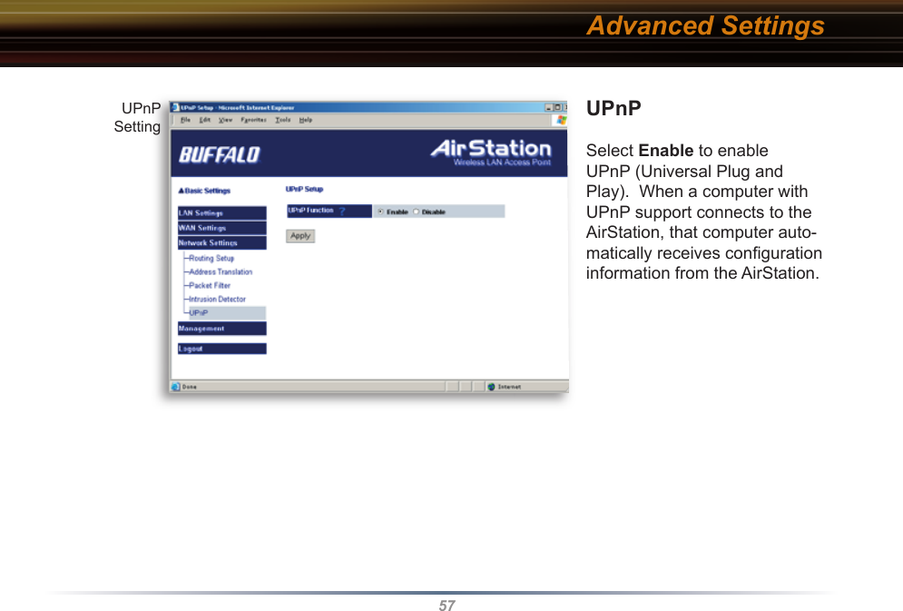
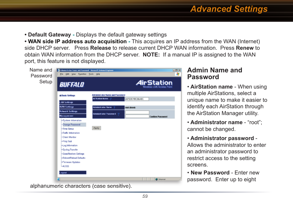
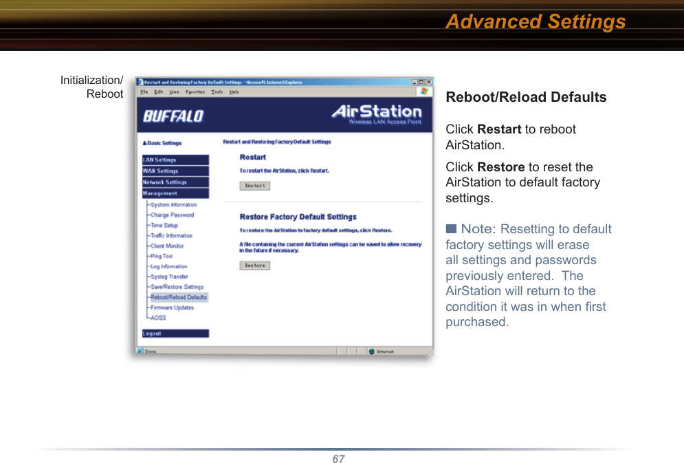
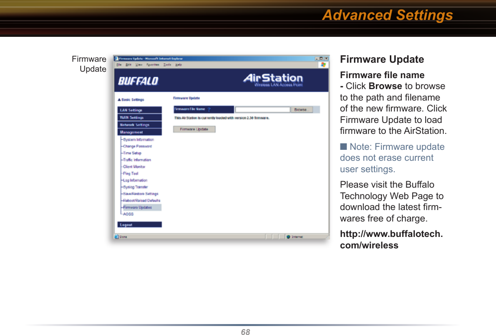
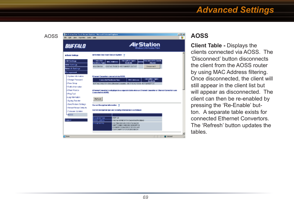
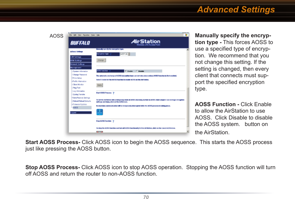
![58Management - • System Information - System information of the AirStation is obtained here.• Model name - Displays model and fi rmware version. • AirStation Name - Displays AirStation host name.• DHCP Server function - Displays whether DHCP is On or Off. • Wireless - Displays such wireless LAN settings as wireless MAC address and wireless fi rmware. The wireless MAC address is required for setting up WDS with other access points. This is the best place to determine the wireless MAC address. If 125* Mbps AfterBurner mode is enabled, then the [AfterBurner] color will be red or grey. When it is red, 125* Mbps AfterBurner is running. When it is grey, 125* Mbps AfterBurner is enabled but not running due to a client being connected at 54 Mbps or another access point is running on the same channel.• LAN - Displays the AirStation LAN settings • WAN - Displays the AirStation WAN settingsAdvanced SettingsSystemInformationSystemSystemInformationInformation](https://usermanual.wiki/BUFFALO/09101457-0.User-manual-part-2/User-Guide-554644-Page-8.png)