BUFFALO 09101669-0 11g Access Point with 11g Access Point Client User Manual WLAG54C Users indd
BUFFALO INC. 11g Access Point with 11g Access Point Client WLAG54C Users indd
BUFFALO >
Users manual revised

13
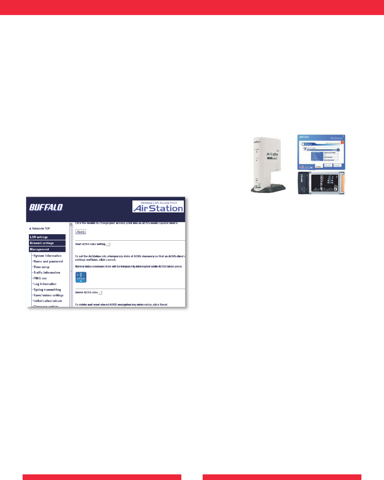
AOSS
Enable/disable AOSS button.
• Enable : Enable A.O.S.S function.
• Disable : Disable A.O.S.S function.Exchange of AOSS. encryption keys can not be used until AOSS is enabled.
Start AOSS Sequence
Functions as an AOSS button on the AirStation unit.
The AirStation starts security key exchange, when the AOSS button is pushed.
The AOSS button is grayed out, when AOSS function is disabled.
Up to 24 clients are allow to connect to the AirStation by AOSS feature.
Stop AOSS
Clear AOSS configuration data.
14
USING AOSS
AOSS (AirStation One-Touch Secure System) is a simple, one-touch setup for connecting wireless clients to an access point while
setting up the most secure possible connection.
Users no longer need to worry about choosing the proper security protocols, IP addresses, or SSID’s. The intelligence of AOSS
determines the most optimal connection and confi gures itself in seconds.
■ NOTE: AOSS automatically creates a secure connection between your AOSS Access Point and client. You must have a Buffalo
AOSS enabled wireless client device to use the AOSS features of your AOSS Access Point/Router.
The INIT switch initiates AOSS mode now. If you want to restore the factory default settings, hold the INIT switch up to 5 seconds
when turn the unit on.
◗ Confi gure your WLA2-G54C’s network connection by referring to the above mentioned instructions.
◗ Once the WLA2-G54C has been confi gured, follow the directions to install your wireless client device and its drivers if necessary.
Certain wireless client adapters require client software to confi gure them. If your device has a Client Manager, then install it as
well.
■ NOTE: If the wireless client adapter is installed on a PC, then the AOSS client
manager will need to be installed as well. If your wireless client adapter is a standalone
device that does not require a PC, then just power up the device.
Standalone Devices: Ethernet Converters and Access Point Bridges
Client Manager Devices: CardBus, USB, and PCI Adapters.
Standalone
AOSS Device
Client Manager
Device
◗ Now that the WLA2-G54C and wireless client adapter are
installed, you can use AOSS to confi gure them.
◗ To begin the confi guration, press the AOSS button in the WLA2-
G54C’s confi guration. The AOSS menus can be found under the
‘Advanced’ Confi guration, Management, AOSS. The status screen
will briefl y show that it is in AOSS mode. The WLA2-G54C’s
Wireless Light may turn on and off.
■ NOTE: AOSS mode will stay active for a period of two
minutes. This is the time-slot required to initiate the wireless
client adapter.
◗ Refer to your wireless client adapter’s AOSS supplement to initiate the wireless client adapter’s AOSS mode.
◗ Once the client adapter has begun communicating with the AOSS router, AOSS client will report a successful AOSS connection.
This indicates that the AOSS process has begun and the two devices are confi guring themselves. Please refer to your wireless client
adapter’s supplement for the remainder of the setup.
ADDITIONAL AOSS INFORMATION:
◗ Only one AOSS wireless client adapter can be confi gured to the AOSS access point at a time. Thus, the button will need to be
repressed for each additional AOSS wireless client adapter that will be connected.
◗ It is not necessary to reconfi gure AOSS client devices that have already been confi gured via AOSS, unless signifi cant changes have
been made to the wireless network.
◗ Do not attempt to confi gure two separate AOSS networks at the same time, as it may cause undesired confi gurations.
◗ If an undesired client has connected via AOSS, it can be disconnected from within the WLA2-G54C’s advanced confi guration
AOSS menus.
ADDITIONAL INFORMATION
Please check the Buffalo Web site for the latest information and any corrections done for this manual.
For more information, please consult one of the following:
• The on-line help system of your AirStation wireless system - for in for ma tion about software and driver func tion al ity.
• The AirStation website at our local website indicated last page.
- for frequently asked questions (FAQ’s) and Software Updates.

15
Specifications
WLA2-G54C Physical Specifications
Dimensions (WxHxD) 56 x 120 x 92 mm
Weight: 0.56lbs (256g)
Temperature & Humidity
Operation 0 to 40 deg. C
Maximum humidity 80%
Transit/Storage 0 to 40 deg. C
Maximum humidity 80% (no condensation)
Power Characteristics
Transmit Mode 0.8A (Normal)
Power Supply 3.3V
Regulatory Information A
Wireless communication is often subject to local radio
regulations. Although AirStation wireless networking products
have been designed for operation in the license-free 2.4 GHz
band, local radio regulations may impose limitations on the use
of wireless communication equipment.
Networking Characteristics Compatibility
• IEEE 802.11 Standard for Wireless LANs (DSSS)
• Wi-Fi (Wireless Fidelity) certified by the Wi-Fi Alliance.
Host Operating System
Microsoft Windows® ME/98/NT4.0/2000/XP
Media Access Protocol
CSMA/CA (Collision Avoidance) with Acknowledgment (ACK)
Radio Characteristics (Typical Indoor Ranges)
R-F Frequency Band 2.4 GHz (2400-2483 MHz)
11 selectable sub-channels
Modulation Technique Direct Sequence Spread Spectrum
• CCK for High & Medium Transmit Rate
• DQPSK for Standard Transmit Rate
• DBPSK for Low Transmit Rate
Spreading 11-chip Barker Sequence
Bit Error Rate (BER) Better than 10 -5
Nominal Output Power 15 dBm (32mW)
Transmit Rate / Range
High Speed 54Mbps
Standard Speed 20 Mbps
Low Speed 1 Mbps
Open Office Environment
160 m (525 ft.)
270 m (885 ft.)
400 m (1300 ft.)
550 m (1750 ft.)Semi-Open Office Environment
50 m (165 ft.)
70 m (230 ft.)
90 m (300 ft.)
115 m (375 ft.)
Closed Office
25 m (80 ft.)
35 m (115 ft.)
40 m (130 ft.)
50 m (165 ft.)
Receiver Sensitivity -69dBm, -72dBm, -77dBm, -81dBm, -85dBm,
-88dBm -87dBm -90 dBm -92 dBm (depends on data rate)
Delay Spread (at FER of <1%) 65 ns 225 ns 400 ns 500 ns (depends
on data rate)
• The range of wireless devices can be affected by metal surfaces,
solid high-density materials and obstacles in the signal path.
• In Open Office environments, clients can “see” each other, i.e.
there are no physical obstructions between them.
• In Semi-open Office environments, work space is separated by
room dividers; client cards are at desktop level.
• In Closed Office environments, workspace is separated by
floor-to-ceiling brick walls.
NOTE:
The range values listed in Table “Radio Characteristics” are
typical distances as measured at Buffalo Technology AirStation
laboratories. These values are provided for your guidance but
may vary according to the actual radio conditions at the location
where the AirStation product is installed.
AirStation IEEE 802.11 Channel Sets
The range of the wireless signal is related to the Transmit Rate of
the wireless communication. Communications at a lower Transmit
range may travel longer distances.
Center Channel ID FCC
1 2412
2 2417
3 2422
4 2427
5 2432
6 2437
7 2442
8 2447
9 2452
10 2457
11 2462 1
1 default channel

16
provided by your LAN Administrator. Make changes if necessary,
and click OK.
5. When prompted, restart your computer.
B. 1.3 Other Problems
Please refer to our local web site indicated last page.
B Troubleshooting
B.1 Common Troubleshooting Tips B
Common Problems:
• Out of range, client cannot connect to the AirStation.
• Configuration mismatch, client cannot connect to the
AirStation.
• Absence or conflict with the Client Driver.
• Conflict of another device with the AirStation hardware.
B.1.1 LED Activity B
Monitoring LED activity helps identify problems.
- Power LED should be GREEN,
- Wireless LED should be GREEN if the line is active. If is it
blinking GREEN, wireless communication is active.
- Ethernet LED should be GREEN (100Mbps) or AMBER
(10Mbps) while the communication is active.
DIAG LED Activity
Unplug the power for three seconds. Plug the power back in to
monitor the DIAG LEDs during start-up.
Table B.1.1
DIAG LED Activity Table
DIAG LED Display
Action - Description/Cause
Red flash, 3 times
Starting:
A problem in the wired LAN side
Red flash, 4 times
Starting:
A problem in the wireless LAN side
B. 1.2 LEDs Work But Client PC Cannot Connect to Network
If the LEDs indicate that the network is working properly (Power
LED is on, Transmit/Receive LED blinks), check the TCP/IP settings
of the network.
Changing Client TCP/IP Settings in Windows
Consult the LAN Administrator for TCP/IP settings.
To add or change the TCP/IP Settings:
1. On the Windows task bar click Start.
2. Select Settings, then Control Panel.
3. Double-click on the Network icon to view the Network
Properties.
4. From the list of installed components, verify the TCP/IP ->
Buffalo WLI-USB-L11G wireless LAN adapter protocol (or
appropriate wireless LAN adapter) is installed.
• If this protocol is not yet installed, click the Add button and
select the TCP/IP protocol from the list. Refer to Windows Help
for more information.
• If this protocol is installed, select this protocol and click the
Properties button. Verify the parameters match the settings

17
Glossary
10BaseT or 100BaseTx: 802.3 based Ethernet network that uses
UTP (Unshielded twisted pair) cable and a star topology. 10 is
10 Mbps and 100 is 100 Mbps.
802.1x: The standard for wireless LAN authentication used
between an AP and a client. 802.1x with EAP will initiate key
handling.
Ad-Hoc Network: The wireless network based on a peer-to-peer
communications session. Also referred to as AdHoc.
Bandwidth: The transmission capacity of a computer or a
communication channel, stated in Megabits per second (Mbps).
BSS (Basic Service Set): An 802.11 networking framework that
includes an .
Bus Mastering: A system in which the specified Input/Output
device (e.g. NIC Card) can perform tasks without the intervention
of the CPU.
Client: A PC or workstation on a network.
Default Gateway: The IP Address of either the nearest bridge or
server for the LAN.
Default Parameter: Parameter set by the manufacturer.
Destination Address: The address portion of a packet that
identifies the intended recipient station.
DNS (Domain Name System): System used to map readable
machine names into IP addresses
Driver: Software that interfaces a computer with a specific
hardware device.
DSSS (Direct Sequence Spread Spectrum): Method of spreading
a wireless signal into wide frequency bandwidth.
DTE (Data Terminal Equipment): Device that controls data
flowing to and from a computer.
Dynamic IP Address: An IP address that is automatically assigned
to a client station in a TCP/IP network, typically by a DHCP
server.
ESS (Extended Service Set): A set of two or more BSSs that form
a single sub-network. SSID is user identification used in the ESS
LAN configuration.
Ethernet: The most widely used architecture for Local Area
Networks (LANs). It is a shared-media network architecture.
IEEE 802.3/802.3u standard details its functionality.
Ethernet cable: A wire similar to telephone cable that carries
signals between Ethernet devices.
File and Print Sharing: A Microsoft application that allows
computers on a network to share files and printers.
Firmware: Programming inserted into programmable read-
only memory, thus becoming a permanent part of a computing
device.
Full-Duplex: To transmit on the same channel in both directions
simultaneously.
Half-duplex: To transmit on the same channel in both directions,
one direction at a time.
Hub: A device which allows connection of computers and other
devices to form a LAN.
IEEE (Institute of Electrical and Electronics Engineers): The
professional organization which promotes development of
electronics technology.
IP (Internet Protocol) Address: A unique 32-binary-digit number
that identifies each sender or receiver of information sent in
packets.
Infrastructure: A wireless network or other small network
in which the wireless network devices are made a part of the
network through the .
ISP (Internet Service Provider): A company that provides access
to the Internet and other related services.
IV (Initialization Vector): The header section of a message
packet.
LAN (Local Area Network): A group of computers and peripheral
devices connected to share resources.
LED (Light Emitting Diode): The lights on a hardware device
representing the activity through the ports.
MAC (Medium Access Control) Address: A unique number that
distinguishes network cards.
Mbps (Mega Bits Per Second): A measurement of millions of
bits per second.
MHz (MegaHertz): One million cycles per second.
NAT (Network Address Translation): An internet standard that
enables a LAN to use one set of IP addresses for internal traffic
and a second set for external traffic.
NIC (Network Interface Card): An expansion card connected to
a computer so the computer can be connected to a network.
Packet: A block of data that is transferred as a single unit, also
called a frame or a block.
Packet Filtering: Discarding unwanted network traffic based on
its originating address or its type.
Ping (Packet Internet Groper): An Internet utility used to
determine whether a particular IP address is online.
Plug and Play: Hardware that, once installed (“plugged in”), can
immediately be used (“played”), as opposed to hardware that
requires manual configuration.
PoE (Power over Ethernet): A mechanism to send DC power to
a device using a CAT5 Ethernet cable.
Protocol: A standard way of exchanging information between
computers.
RADIUS (Remote Authentication Dial In User Service): A server
that issues authentication key to clients.
Repeater Hub: A device that collects, strengthens and transmits
information to all connected devices, allowing the network to be
extended to accommodate additional workstations.
RC4: The encryption algorithm that is used in WEP.

18
RJ-45 connector: An 8-pin connector used between a twisted
pair cable and a data transmission device.
Bridge: Device that can connect individual LANs and remote
sites to a server.
Roaming: The ability to use a wireless device while moving from
one to another without losing the connection.
SMTP (Simple Mail Transfer Protocol): The protocol used to
define and deliver electronic mail (e-mail) from one location to
another.
SNMP (Simple Network Management Protocol: An application
layer protocol that outlines the formal structure for communication
among network devices.
Static IP Address: A permanent IP address is assigned to a
node in a TCP/IP network. Also known as global IP.
Subnet Mask: An eight-byte address divided into 4 parts
separated by periods.
TCP/IP (Transmission Control Protocol/Internet Protocol:
Protocol used by computers when communicating across the
Internet or Intranet.
TKIP (Temporal Key Integrity Protocol): An encryption
method replacing WEP. TKIP uses random IV and frequent key
exchanges.
UDP (User Datagram Protocol): A communication method
(protocol) that offers a limited amount of service when
messages are exchanged between computers in a network.
UDP is used as an alternative to TCP/IP.
Static IP Address: A permanent IP address is assigned to a
node in a TCP/IP network. Also known as global IP.
Subnet Mask: An eight-byte address divided into 4 parts
separated by periods.
WAN (Wide Area Network): A networking system covering a
wide geographical area.
WEP (Wired Equivalent Privacy): An encryption method
based on 64 or 128bit algorithm.
Web Browser: A software program that allows viewing of web
pages.
Wi-Fi (Wireless Fidelity): An organization that tests and
assures interoperability among WLAN devices.
Wire Speed: The maximum speed at which a given packet
can be transferred using Ethernet and Fast Ethernet standard
specifications.
WLAN (Wireless LAN): A LAN topology using wireless
devices.
WPA (Wi-Fi Protected Access): An encryption method
replacing WEP.
VPN (Virtual Private Network): A security method to connect
remote LAN users to a corporate LAN system.
FCC/CE / R&TTE
Federal Communication Commission
Interference Statement
This equipment has been tested and found to comply with the limits
for a Class B digital device, pursuant to Part 15 of the FCC Rules. These
limits are designed to provide reasonable protection against harmful
interference in a residential installation. This equipment generates, uses
and can radiate radio frequency energy and, if not installed and used in
accordance with the instructions, may cause harmful interference to radio
communications. However, there is no guarantee that interference will
not occur in a particular installation. If this equipment does cause harmful
interference to radio or television reception, which can be determined
by turning the equipment off and on, the user is encouraged to try to
correct the interference by one of the following measures:
- Reorient or relocate the receiving antenna.
- Increase the separation between the equipment and receiver.
- Connect the equipment into an outlet on a circuit different from that
to which the receiver is connected.
- Consult the dealer or an experienced radio/TV technician for help.
FCC Caution: To assure continued compliance, (example - use only
shielded interface cables when connecting to computer or peripheral
devices). Any changes or modifications not expressly approved by the
party responsible for compliance could void the user’s authority to
operate this equipment.
This device complies with Part 15 of the FCC Rules. Operation is subject
to the following two conditions: (1) This device may not cause harmful
interference, and (2) this device must accept any interference received,
including interference that may cause undesired operation.
IMPORTANT NOTE:
FCC RF Radiation Exposure Statement:
This equipment complies with FCC RF radiation exposure limits set forth
for an uncontrolled environment. This equipment should be installed
and operated with a minimum distance of 20 centimeters between the
radiator and your body.
This transmitter must not be co-located or operating in conjunction
with any other antenna or transmitter.
R&TTE Compliance Statement
This equipment complies with all the requirements of the DIRECTIVE
1999/5/EC OF THE EUROPEAN PARLIAMENT AND THE COUNCIL
of 9 March 1999 on radio equipment and telecommunication terminal
Equipment and the mutual recognition of their conformity (R&TTE).
The R&TTE Directive repeals and replaces in the directive 98/13/EEC
(Telecommunications Terminal Equipment and Satellite Earth Station
Equipment) As of April 8, 2000.
Europe – EU Declaration of Conformity
This device complies with the essential requirements of the R&TTE
Directive 1999/5/EC. The following test methods have been applied
in order to prove presumption of compliance with the R&TTE
Directive 1999/5/EC:
◗ EN 60950: 2000
Safety of Information Technology Equipment
◗ EN 300 328-2 V1.2.1 (2001-12)
Technical requirements for spread-spectrum radio equipment
◗ EN 301 489-17 V1.1.1 (2000-09)
EMC requirements for spread-spectrum radio equipment.
This product has external antenna jack on the rear panel.
It is a unique connect type.
This is only for specific external antenna provided by
Buffalo.

19
Safety
This equipment is designed with the utmost care for the safety of
those who install and use it. However, special attention must be paid
to the dangers of electric shock and static electricity when working
with electrical equipment. All guidelines of this manual and of the
computer manufacturer must therefore be allowed at all times to
ensure the safe use of the equipment.
Intended use
This device is a 2.4 GHz wireless LAN transceiver, intended for
indoor home and office use in all EU and EFTA member states.
EU Countries intended for use
This device is intended for indoor Home and office use in the
following countries:
Austria, Belgium, Germany, Denmark, Spain, Greece, France, Finland,
Italy, Ireland, Luxembourg, The Netherlands, Portugal, Sweden, United
Kingdom, Cyprus, Czech Republic, Estonia, Hungry, Latvia, Lithuania,
Malta, Poland, Slovak Republic and Slovenia.
The device is also authorised for use in all EFTA member states
Iceland, Liechtenstein, Norway and Switzerland.
EU Countries Not intended for use
None.
Potential restrictive use
France: Only channels 10,11,12, and13
Potential restrictive use
This device is a 2.4 GHz wireless LAN transceiver, intended for
indoor home and office use in all EU and EFTA member states, except
in France, Belgium
and Italy where restrictive use applies.
In Italy the end-user should apply for a license at the national
spectrum authorities in order to obtain an authorization to use the
device for setting up outdoor radio links.
In Belgium there is a restriction in outdoor use. The frequency range
in which outdoor operation in Belgium is permitted is 2460 – 2483.5
MHz.
This device may not be used for setting up outdoor radio links in
France. For more information see http://www.anfr.fr/ and/or
http://www.art-telecom.fr
BUFFALO WARRANTY STATEMENT
Buffalo products come with a 2-year limited warranty from the date
of purchase.
Buffalo Technology warrants in good operating condition for the
warranty period. This warranty does not include non-Buffalo
Technology installed components. If the Buffalo product malfunctions
during the warranty period, Buffalo Technology will, at its discretion,
repair or replace the product at no charge, provided the product
has not been subjected to misuse, abuse or non-Buffalo Technology
authorized alterations, modifications or repairs. When returning a
product, include your original proof of purchase. Return requests
cannot be processed without proof of purchase. Shipment of returned
product to Buffalo Technology is the responsibility of the purchaser.
All expressed and implied warranties for the Buffalo product line
including, but not limited to, the warranties of merchantability and
fitness for a particular purpose, are limited in duration to the above
period.
Under no circumstances shall Buffalo Technology be liable in any way
to the user for damages, including any lost profits, lost savings or
other incidental or consequential damages arising out of the use of,
or inability to use, the Buffalo products.
Buffalo Technology reserves the right to revise or update its products,
software, or documentation without obligation to notify any individual
or entity.
Important Notice
Please have your proof of purchase receipt to get warranty support.
All defective products shall be returned with a copy of proof of
purchase.
In no event shall Buffalo Technology’s liability exceed the price
paid for the product from direct, indirect, special, incidental, or
consequential damages resulting from the use of the product, its
accompanying software, or its documentation. Buffalo Technology
does not offer refunds for any product.

20
MEMO

21
MEMO

22
MEMO

PY00-30030-DM20-01 1-01