BW Broadcast TX50V2 50W FM BROADCAST TX User Manual Technical Manual
BW Broadcast Ltd 50W FM BROADCAST TX Technical Manual
UserManual.wiki
>
BW Broadcast
>
TX50V2 User Manual
Technical Manual
Navigation menu
Upload a User Manual
Namespaces
Wiki Guide
HTML
PDF
Info
Views
User Manual
Discussion / Help
Navigation
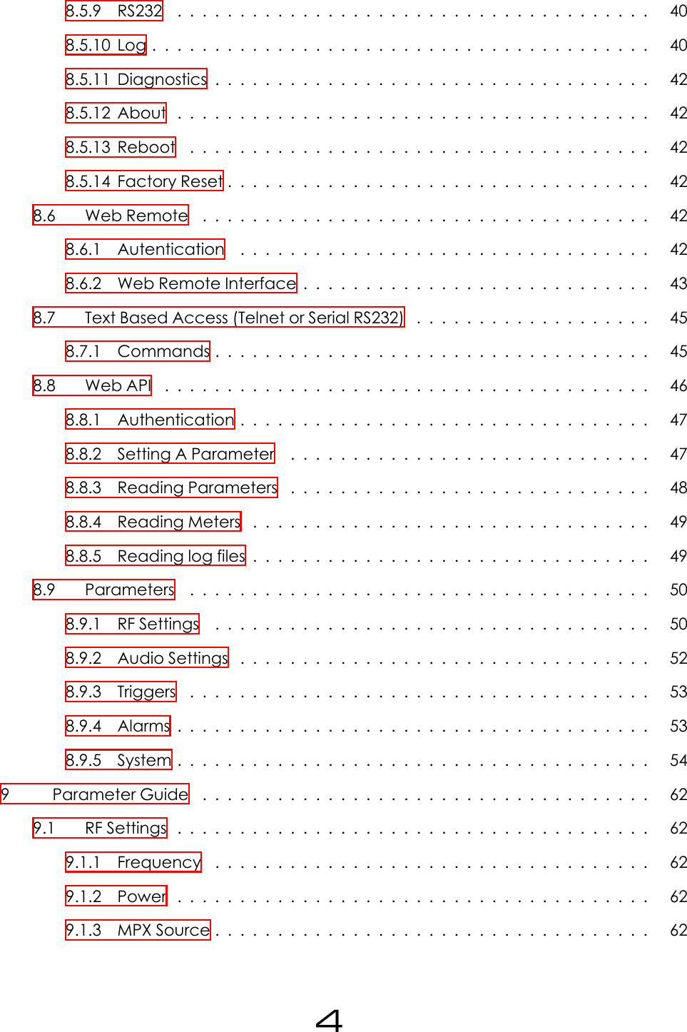


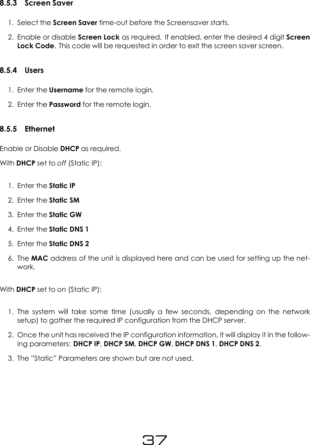

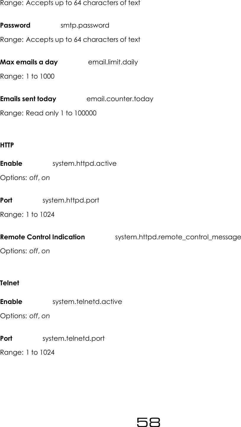
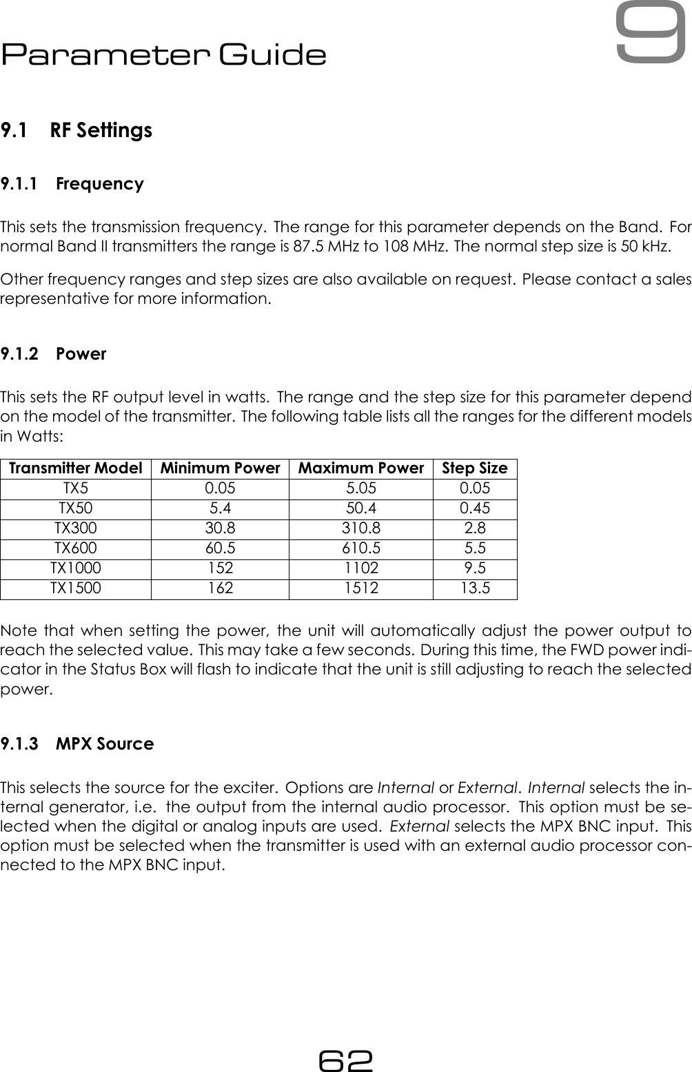
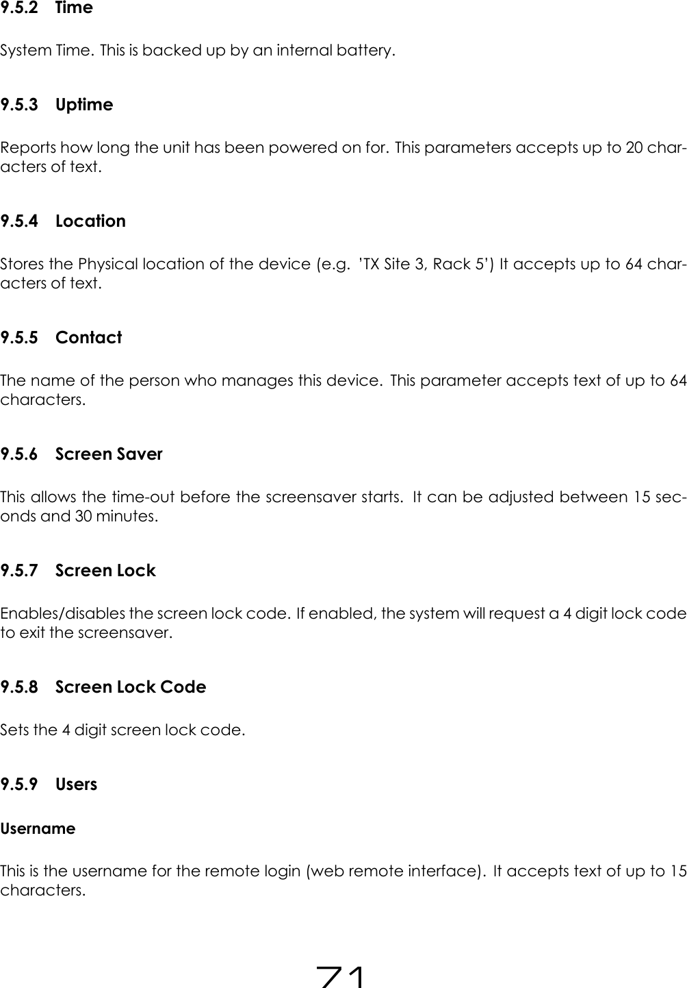
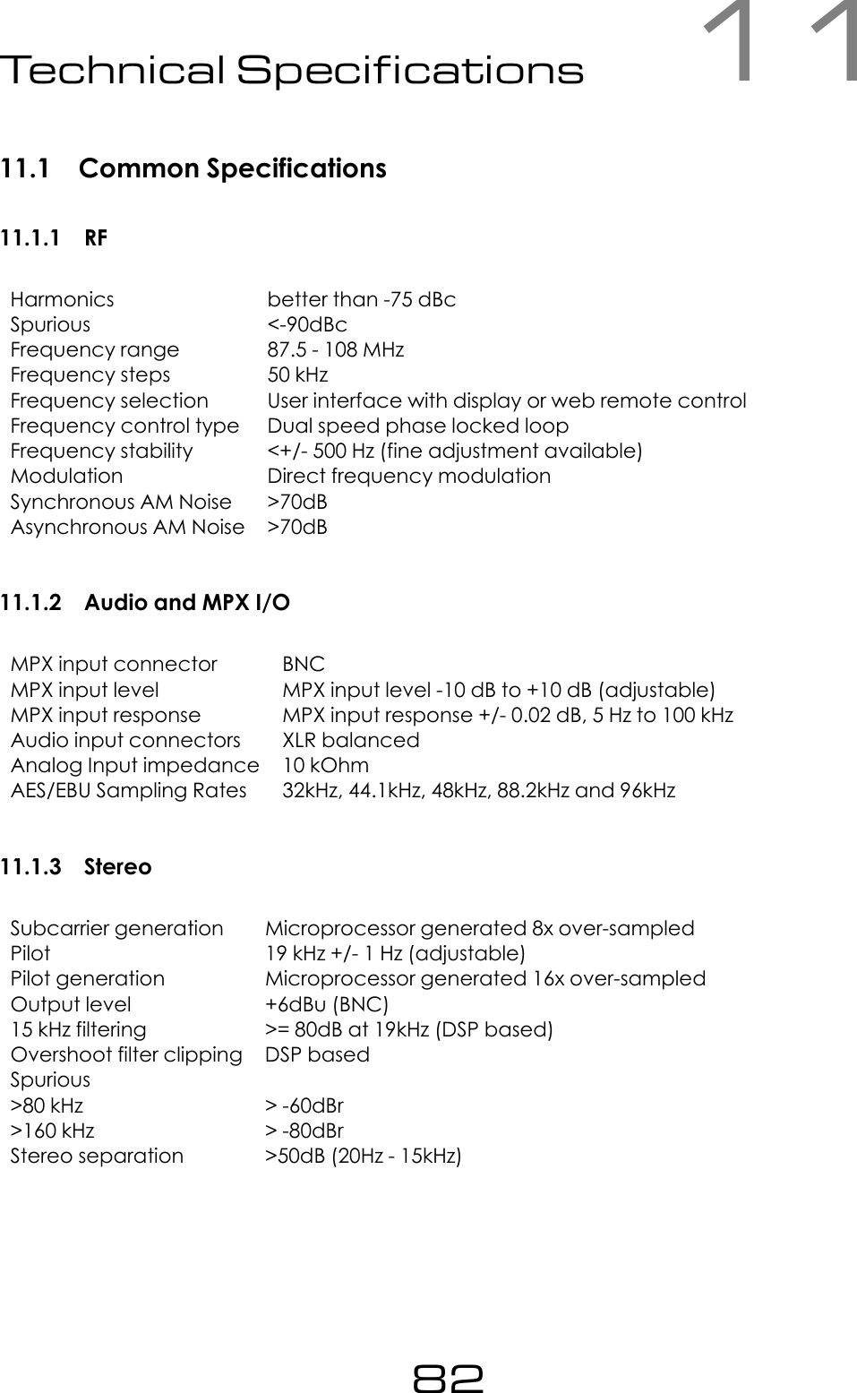
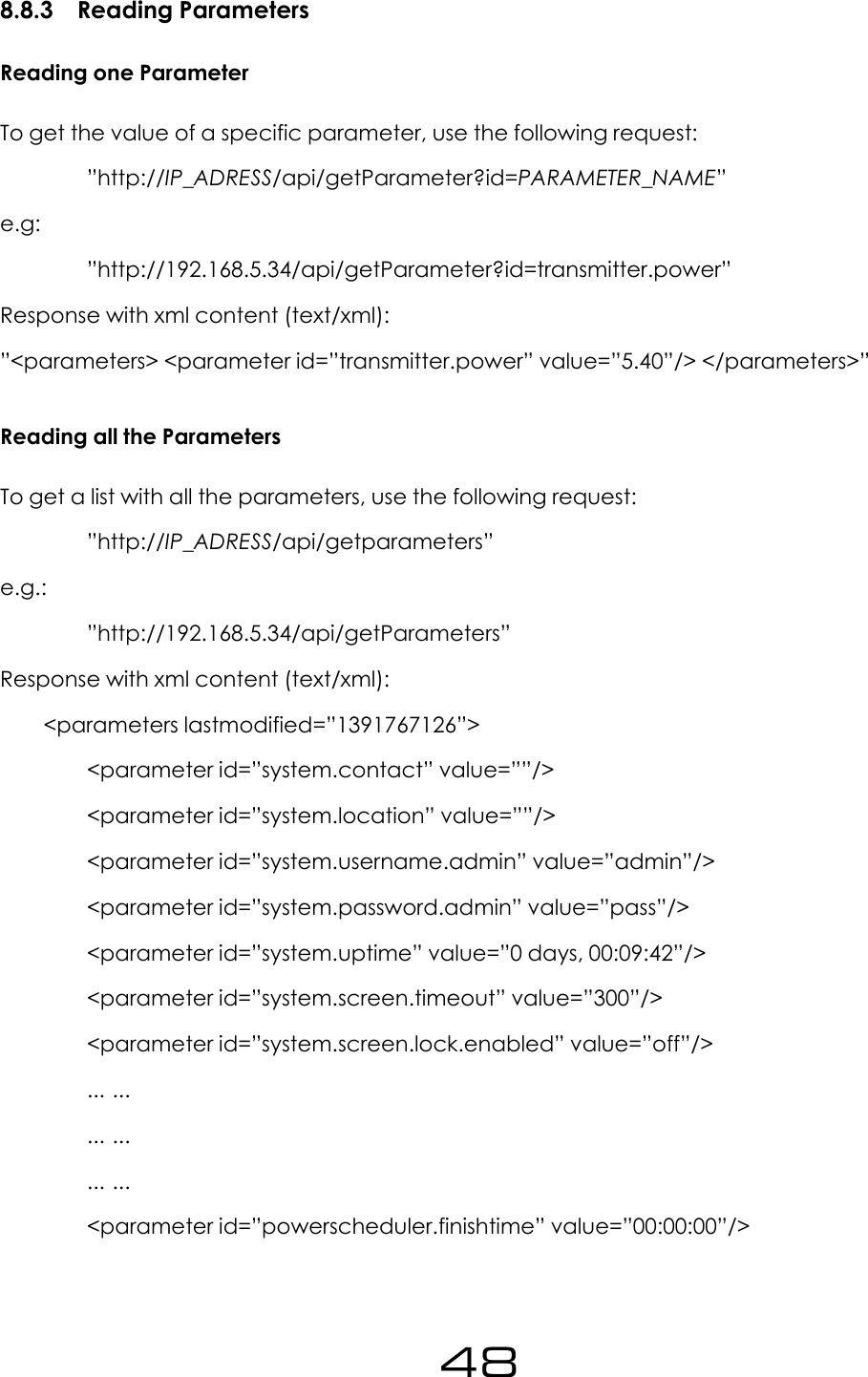
![Logging to a File in internal memoryIf enabled, the system will keep logs of the last 31 days. These logs can be accessed throughthe web remote.An example section from a log file is shown below:2013-04-22 11:40:06 DTLG > M: exciter_locked = 1DTLG > M: peak_deviation = 75kDTLG > M: fwd_power = 250DTLG > M: rev_power = 3DTLG > M: pa_voltage = 30.1DTLG > M: aux_voltage = 15.1DTLG > M: pa_temp = 30.0DTLG > M: cpu_temp = 25.0DTLG > M: tx_input_l = -38.997DTLG > M: tx_input_r = -38.997DTLG > M: agc1 = 0mDTLG > M: agc2 = 0mDTLG > M: agc3 = 0mDTLG > M: agc4 = 0mDTLG > M: lim1 = -5997mDTLG > M: lim2 = -5997mDTLG > M: lim3 = -5997mDTLG > M: lim4 = -5997mDTLG > M: tx_output_l = -14.000DTLG > M: tx_output_r = -14.000DTLG > M: tx_output_mpx = 0mDTLG > P: transmitter.frequency = 98.00MHzDTLG > Alarm status [3-0]: Off Off On OffDTLG > Trigger status [3-0]: On On On On41](https://usermanual.wiki/BW-Broadcast/TX50V2/User-Guide-3222062-Page-41.png)
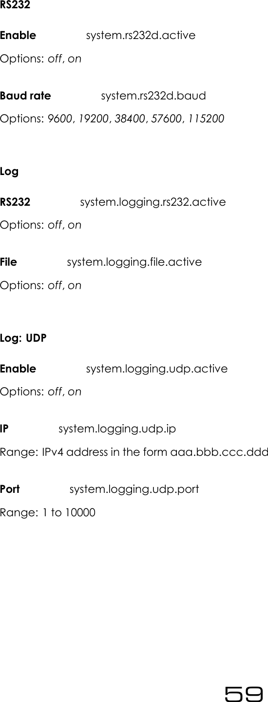
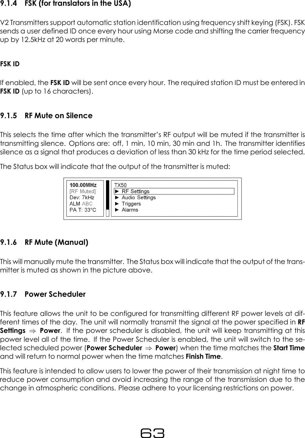
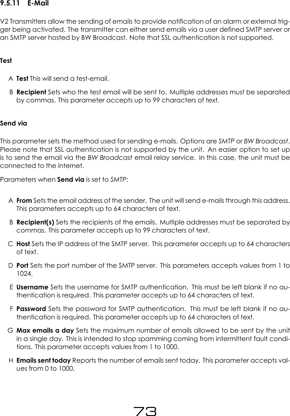
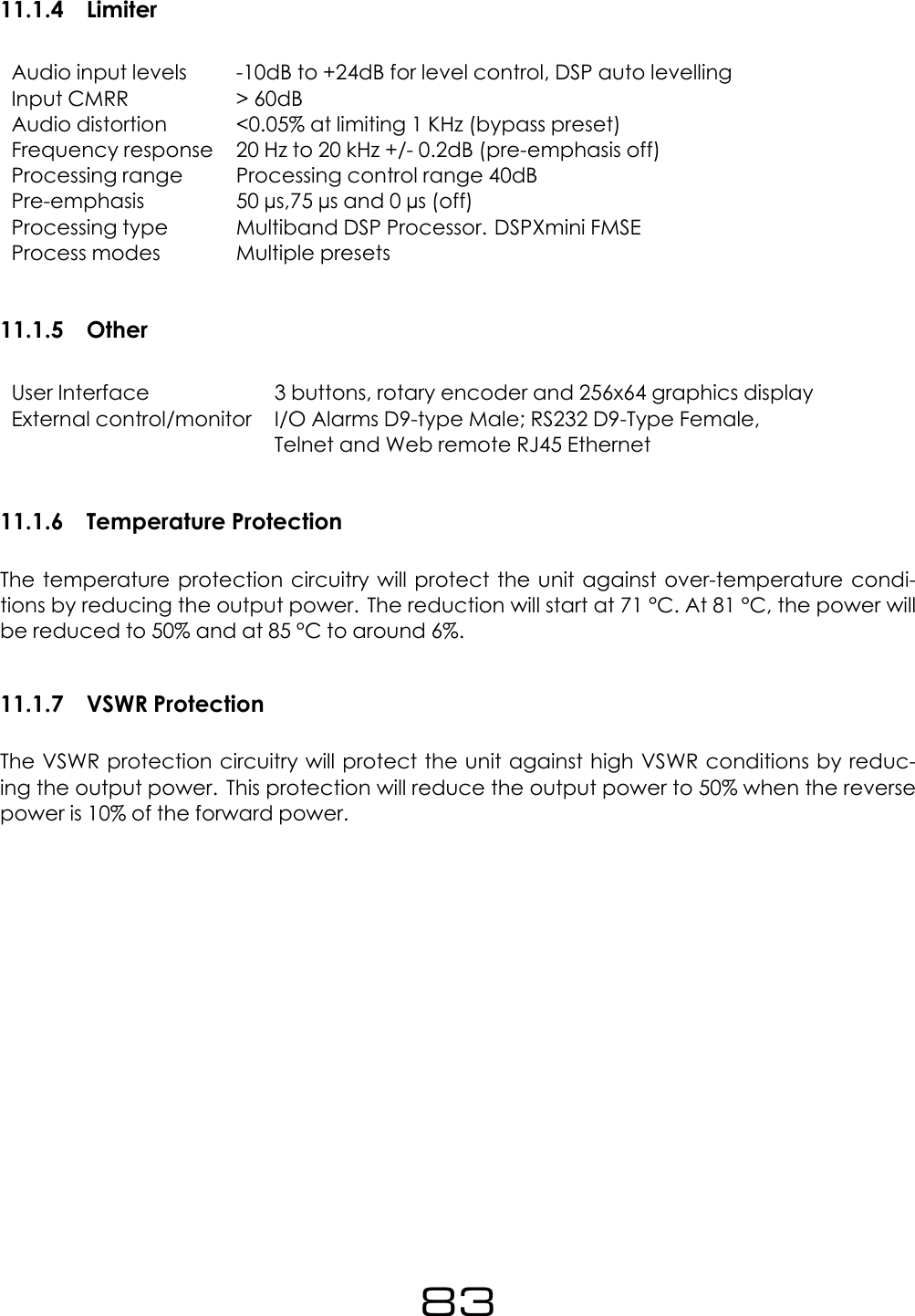
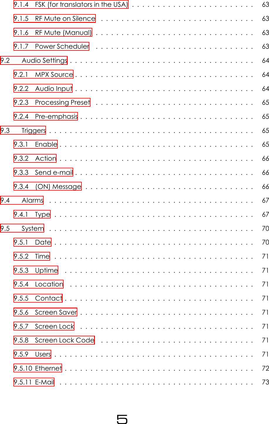
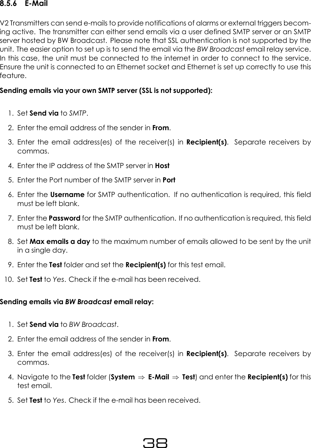
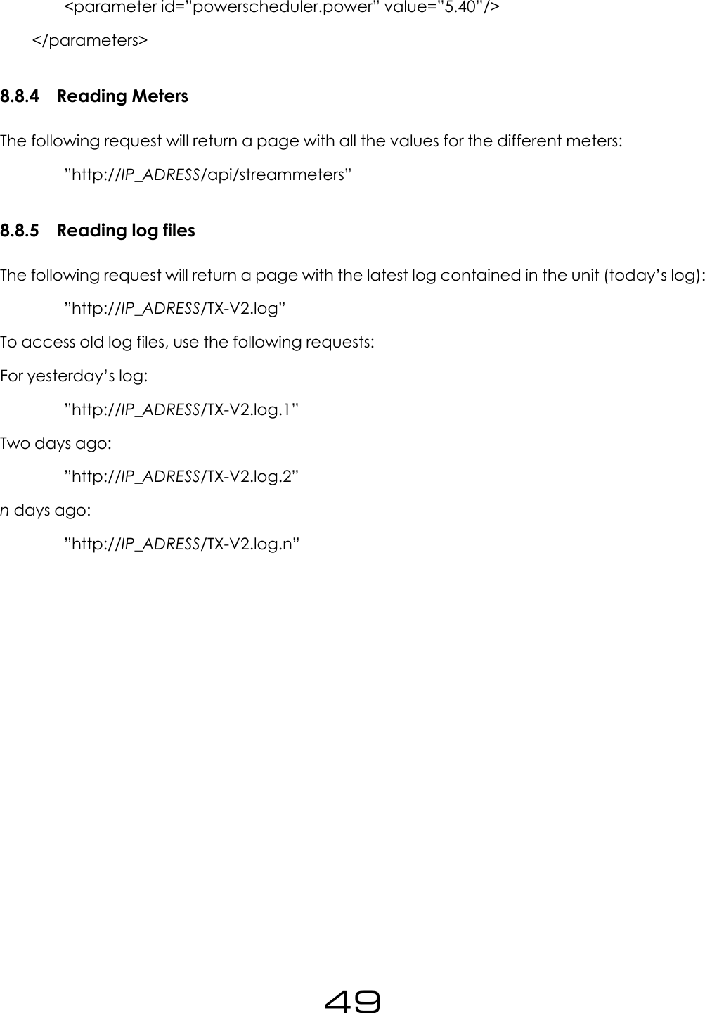
![8.8.1 AuthenticationLogging inIn order be able to read or modify parameters through the Web API, the user must first au-thenticate by sending the following request:”http://IP_ADRESS/api/auth?password=PASSWORDWhere IP_ADRESS is the IP Adress of the unit and PASSWORD is the password set in the FontPanel (System ⇒Users ⇒Password)The unit will respond with a page with xml content (text/xml) and the following content if thelogin attempt is correct:<response login=”true” sid=”884498006”/>Note that the sid value will be different in different sessions.Logging OutThe following request performs a ’log out’. This request should be issued when finished usingthe unit through the Web API.”http://IP_ADDRESS/api/logout”8.8.2 Setting A ParameterTo set parameters, use the following request:”http://IP_ADRESS/api/setParameter?id=PARAMETER_NAME&value=PARAMETER_VALUE”The unit will respond with a page with xml content (text/xml) and the following if the requestwas successful:”<response success=”true”/>”Please refer to the ”Parameter list” subsection for a list with all the parameters available in theunit.E.g. To set the frequency to 99 MHz, issue the following request:”http://192.168.5.34/api/setParameter?id=transmitter.frequency&value=99M”Note that for parameters containing brackets in their name (such as alarm[1].email.active),these characters should be escaped and must be written as ”%5B” and ”%5D” in the htmlrequest. E.g.:”http://192.168.5.34/api/setParameter?id=alarm%5B1%5D.email.active&value=yes”47](https://usermanual.wiki/BW-Broadcast/TX50V2/User-Guide-3222062-Page-47.png)
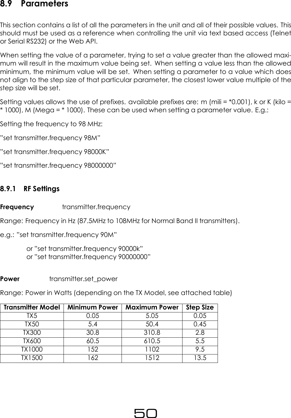
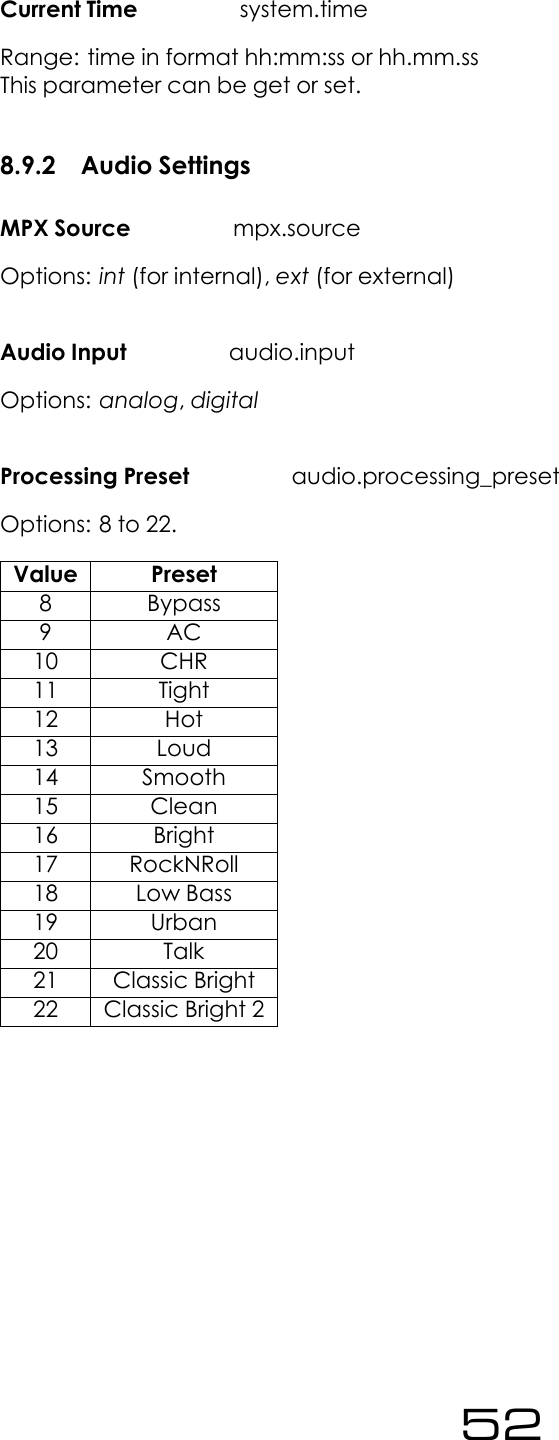
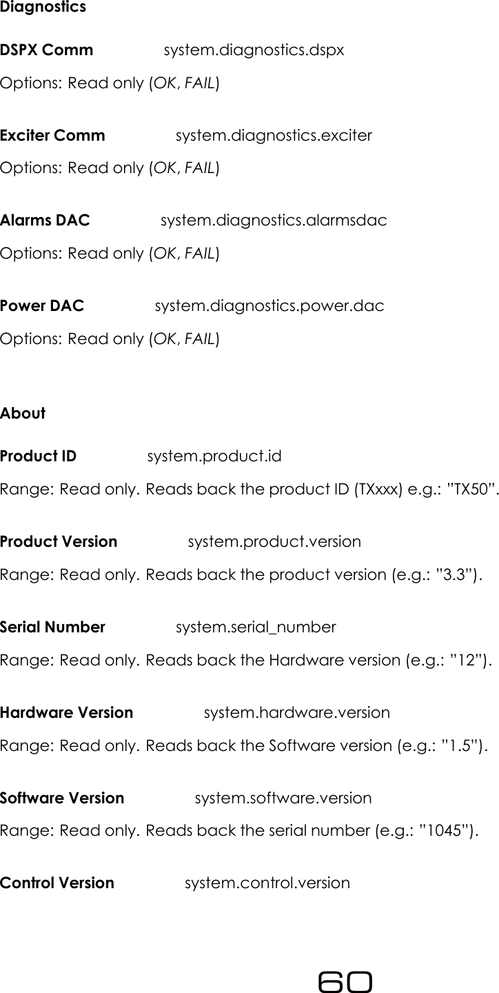
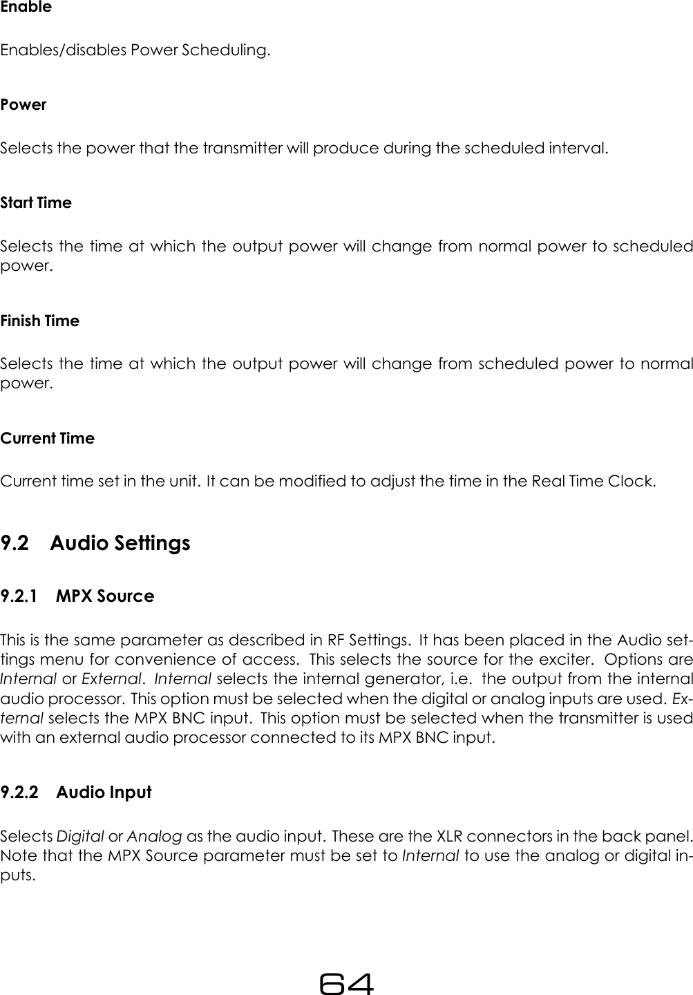
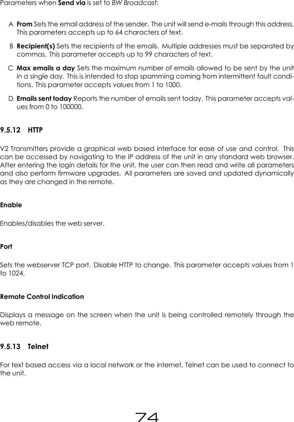
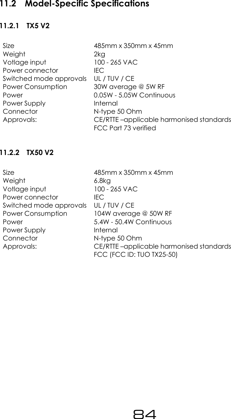
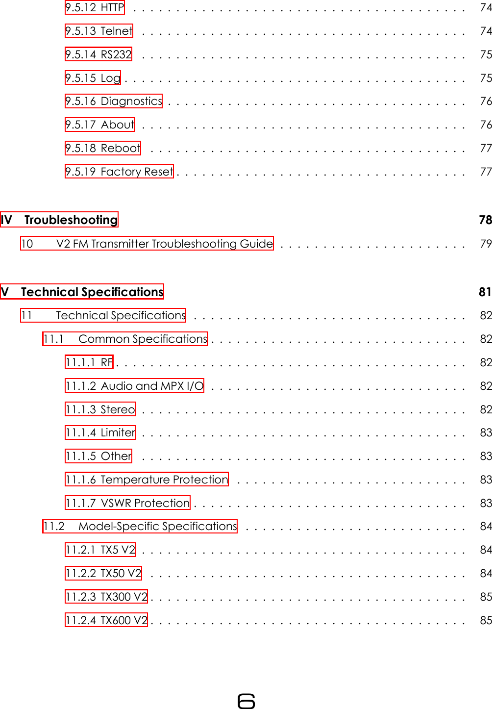
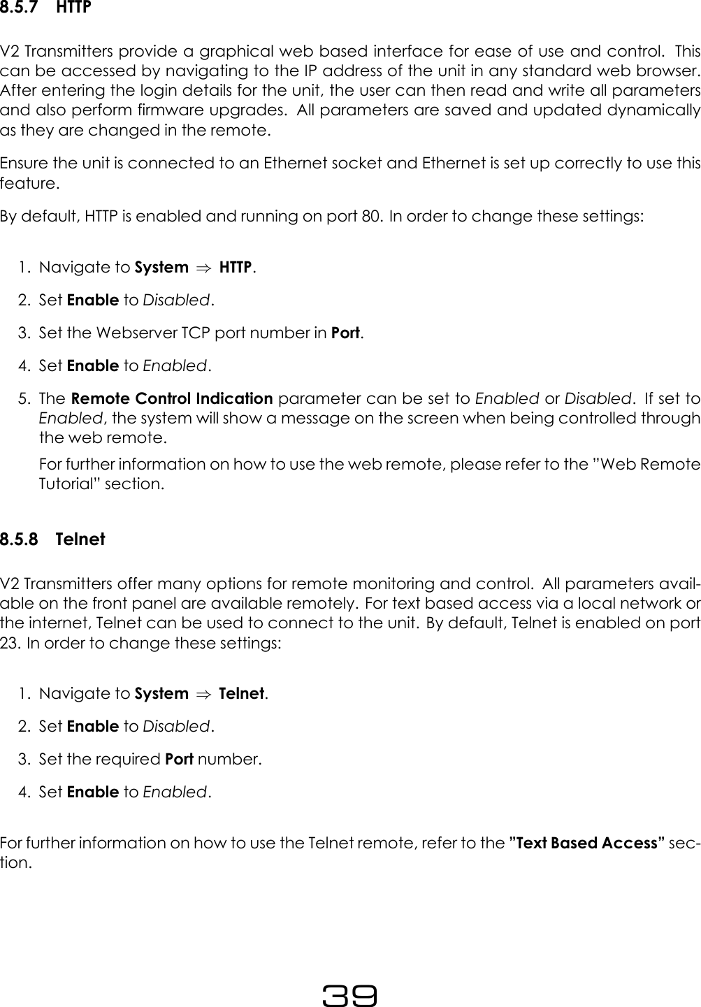
![Pre-Emphasis audio.preemphasisOptions: Options: 0(for Off), 50 (50 us), 75 (75us)Audio Mode audio.stereoOptions: stereo,mono_lr (for Mono L+R), mono_l (Mono L), mono_r (Mono R), swap_lr (SwapL/R)8.9.3 TriggersThe following parameters can be used to configure any trigger (trigger[x], where x is 1 to 4)Enable trigger[x].activeOptions: off,onAction trigger[x].actionOptions: fup (for Frequency Up), fdown (Frequency Down), pup (Power Up), pdown (PowerDown), rfmute (RF Mute), reboot (Reboot)Send e-mail trigger[x].email.activeOptions: Options: yes,no(ON) Message trigger[x].message.onAccepts up to 300 characters of text.8.9.4 AlarmsType alarm[x].typeOptions: alarm,telemetry (for Analog Out)Source (for Analog Out) alarm[x].telemetrysourceOptions: fwdpow (for Fwd Power), revpow (Rev Power), pavolts (PA Volts), auxvolts (AuxVolts), peakmod (Peak Modulation), patemp (PA Temp), rfmute (RF Mute),Modulation Threshold alarm[x].modulation_threshold53](https://usermanual.wiki/BW-Broadcast/TX50V2/User-Guide-3222062-Page-53.png)
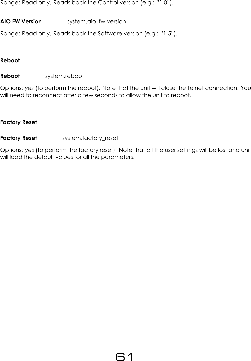
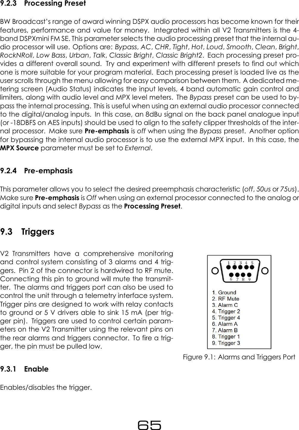
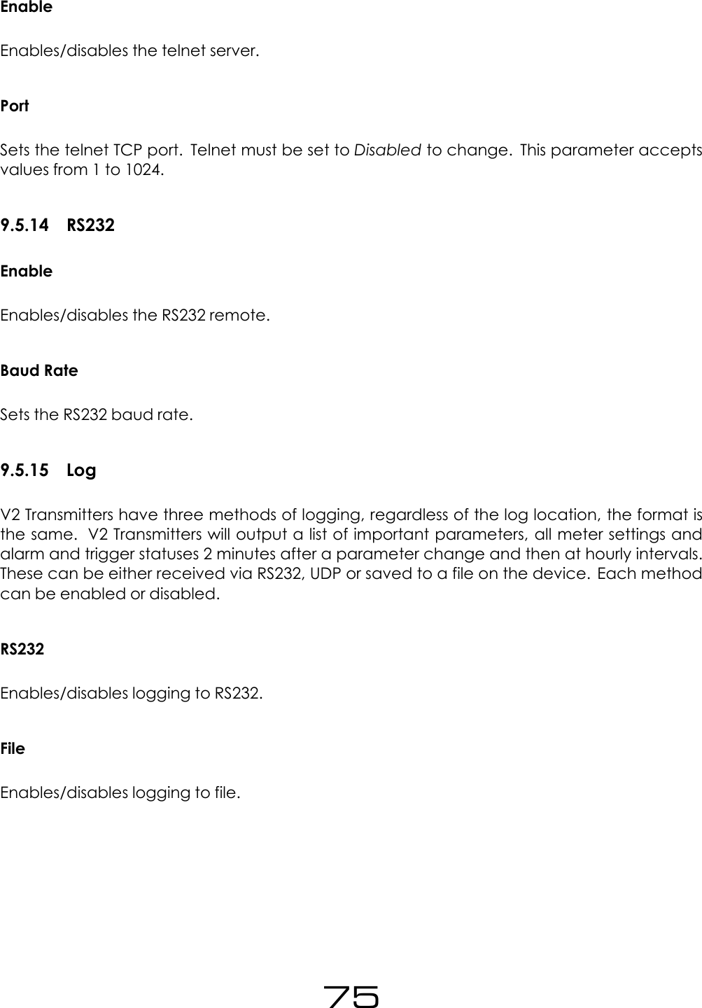
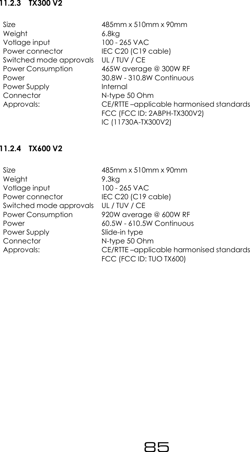
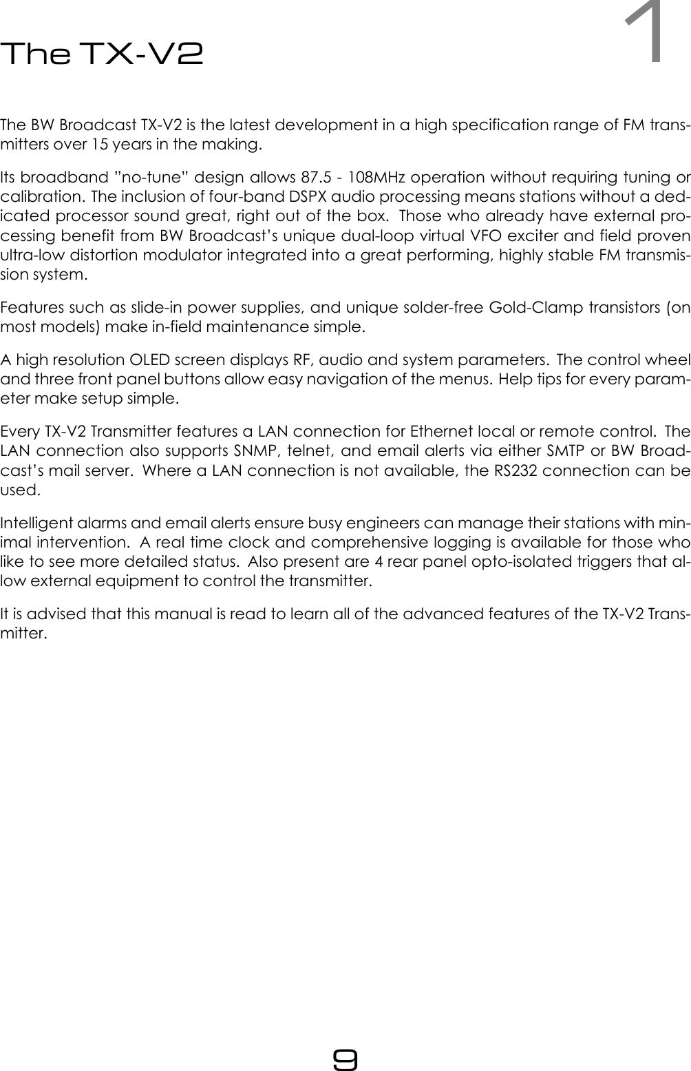
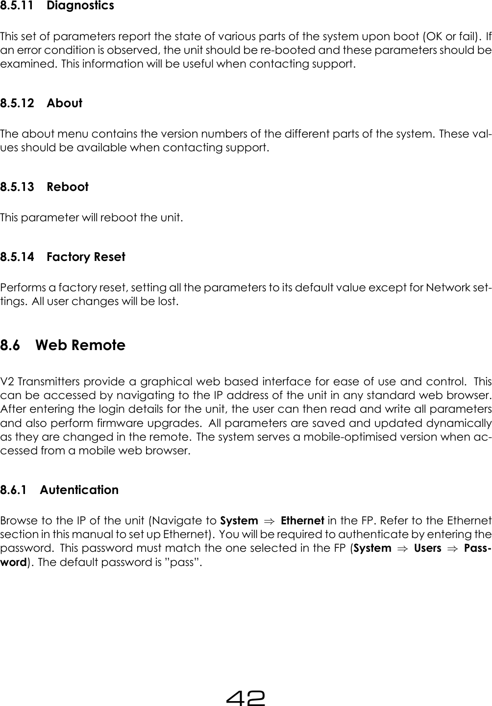
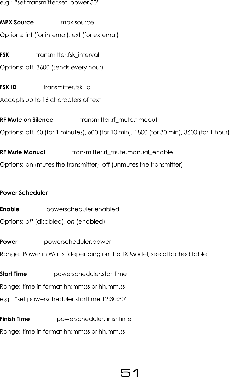
![Range: 1000 to 100000.Fwd Power Threshold alarm[x].fwd_power_thresholdRange: 0 to double the Maximum Power of the transmitter (Refer to transmitter.set_power).Rev Power Threshold alarm[x].rev_power_thresholdRange: 0 to double the Maximum Power of the transmitter (Refer to transmitter.set_power).Pin Polarity alarm[x].polarityOptions: positive (for +ve), negative (for -ve)On Delay alarm[x].on_delayRange: 2 to 600 (seconds)Off Delay alarm[x].off_delayRange: 2 to 600 (seconds)Send e-mail alarm[x].email.activeOptions: yes,no8.9.5 SystemDate system.dateRange: Date in the following format yyyy-mm-dde.g.: ”set system.date 2014-02-22”Time system.timeRange: Time in the following format hh.mm.sse.g.: ”set system.time 22:10:55”Uptime system.uptime54](https://usermanual.wiki/BW-Broadcast/TX50V2/User-Guide-3222062-Page-54.png)
![EthernetDHCP system.ethernet.dhcpOptions: off,onDHCP IP system.ethernet.dhcp.ipRange: Read only. Reads IPv4 address in the form aaa.bbb.ccc.dddDHCP SM system.ethernet.dhcp.smRange: Read only. Reads IPv4 address in the form aaa.bbb.ccc.dddDHCP SM system.ethernet.dhcp.smRange: Read only. Reads IPv4 address in the form aaa.bbb.ccc.dddDHCP GW system.ethernet.dhcp.gwRange: Read only. Reads IPv4 address in the form aaa.bbb.ccc.dddDHCP DNS1 system.ethernet.dhcp.dns[1]Range: Read only. Reads IPv4 address in the form aaa.bbb.ccc.dddDHCP DNS2 system.ethernet.dhcp.dns[2]Range: Read only. Reads IPv4 address in the form aaa.bbb.ccc.dddStatic IP system.ethernet.static.ipRange: Read only. Reads IPv4 address in the form aaa.bbb.ccc.dddStatic SM system.ethernet.static.smRange: Read only. Reads IPv4 address in the form aaa.bbb.ccc.dddStatic GW system.ethernet.static.gwRange: Read only. Reads IPv4 address in the form aaa.bbb.ccc.ddd56](https://usermanual.wiki/BW-Broadcast/TX50V2/User-Guide-3222062-Page-56.png)
![Static DNS 1 system.ethernet.static.dns[1]Range: Read only. Reads IPv4 address in the form aaa.bbb.ccc.dddStatic DNS 2 system.ethernet.static.dns[2]Range: Read only. Reads IPv4 address in the form aaa.bbb.ccc.dddMAC system.ethernet.macRange: Read only. xx:xx:xx:xx:xx:xxE-MailTest email.test.sendOptions: yes (to send a test email. It will automatically go back to no)Recipient(s) (For the test e-mail) email.test.recipientRange: Accepts text up to 99 characters. Multiple addresses must be separated by com-mas.Send Via email.methodOptions: SMTP,BWBroadcastFrom email.fromOptions: Accepts up to 64 characters of text.Recipient(s) email.recipientRange: Accepts up to 99 characters of text.Port smtp.portRange: 1 to 1024Username smtp.username57](https://usermanual.wiki/BW-Broadcast/TX50V2/User-Guide-3222062-Page-57.png)