Badger Meter 2010W ORION SE WATER User Manual Exhibit D Users Manual per 2 1033 b3
Badger Meter Inc ORION SE WATER Exhibit D Users Manual per 2 1033 b3
Exhibit D Users Manual per 2 1033 b3
ORION®
Water Endpoint
Installation Data
ORI-I-79 (1/14/11 10:44 am)
62014-xxx Rev. 1
IMPORTANT:
This manual contains important information.
READ AND KEEP FOR REFERENCE.

ORION® Water Endpoint
Page ii (12-10)

Installation Data
Contents
IDENTIFICATION ................................................................................................................................5
ORION INSTALLATION KITS .............................................................................................................. 5
UNPACKING ....................................................................................................................................... 5
NETWORK Endpoint INSTALLATION ...............................................................................................5
PIT INSTALLATION OPTIONS ............................................................................................................ 6
THROUGH THE LID INSTALLATION ..............................................................................................................................6
BELOW THE LID INSTALLATON .....................................................................................................................................6
INTEGRATED PIT HANGER INSTALLATION ..................................................................................................................7
VAULT INSTALLATION OPTION ..................................................................................................................................... 8
REMOTE INSTALLATION ...................................................................................................................9
REMOTE BOX ENCLOSURE ............................................................................................................................................9
REMOTE BRACKET INSTALLATION ...............................................................................................................................12
WIRING A UNIVERSAL Endpoint ....................................................................................................16
UNIVERSAL Endpoint IDENTIFICATION ....................................................................................................................... 16
REQUIRED SPLICE TOOLS .............................................................................................................................................16
INSTALLATION ...............................................................................................................................................................16
ENCODER REGISTER INSTALLATION .............................................................................................. 18
LICENSE REQUIREMENTS ...............................................................................................................19
Page iii
(12-10)

ORION® Water Endpoint
Page iv (12-10)
Installation Data
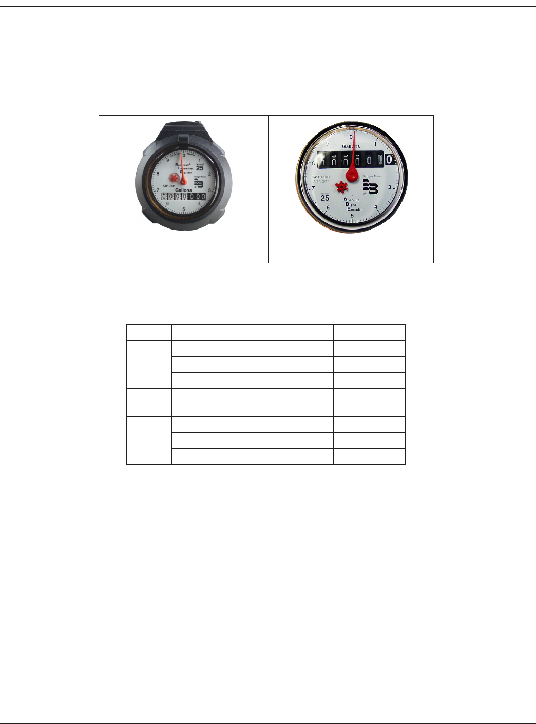
IDENTIFICATION
Each ORION pit endpoint can be identied using the unique numeric serial number located on a tag attached to the wire har-
ness. Each Badger Meter encoder is clearly identied on the face of the register with an assembly number, unit of measure
and meter model.
Recordall Transmitter
Register (RTR®)Absolute Digital
Encoder (ADE®)
Figure 1: Encoders
ORION INSTALLATION KITS
TYPE DESCRIPTION PART NUMBER
PIT
Through Lid Installation Kit 64394-001
Below Lid with Knuckles 64394-003
Armorcast Installation Kit 64394-009
VAULT Vault Installation Kit/Non-Standard
Permalog+®64394-008
REMOTE
Remote Box Enclosure 64394-021
Remote Bracket Kit (RTR) 64394-019
Remote Bracket Kit (ADE) 64394-020
UNPACKING
Carefully remove the pre-wired ORION endpoint and encoder from the shipping carton and inspect the assembly for dam-
age. Retain the contents of the installation kit for use in mounting the endpoint in the eld.
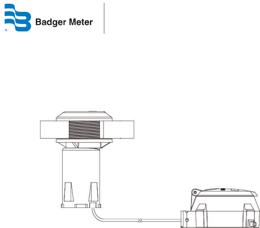
The ORION endpoint (see Figure 2) can be shipped pre-wired to the Badger Meter encoder. When the factory pre-wired,
there is no splicing required and only the mounting of the encoder with tightening of the TORX® seal screw is necessary.
When installing, excess wire should be coiled and cable tied to avoid any damage.
NETWORK Endpoint INSTALLATION
Badger Meter recommends that when installing an endpoint in a pit, the endpoint must be mounted either through or under
the lid of a non-metal pit lid for ecient propagation of the radio signal. If the endpoint is being installed indoors, a wired
radio endpoint should be mounted on the outside of the building or in the oor joist near the outside wall of the building,
and away from large metal objects for ecient propagation of the radio signal.
(12-10) Page 5
ORION® Water Endpoint
PIT INSTALLATION OPTIONS
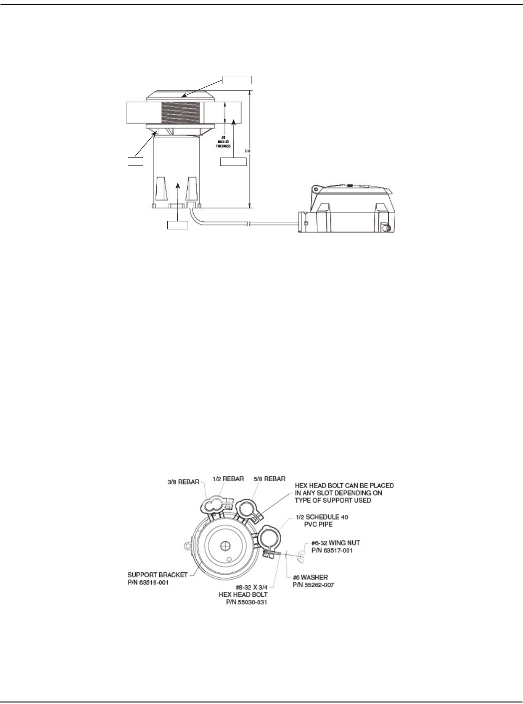
THROUGH THE LID INSTALLATION
Figure 2: ORION Pit Endpoint
To install the endpoint through the lid, follow these steps, per Figure 2:
1. Screw the nut onto the tube threads.
2. Insert the tube through the bottom of the lid.
3. Screw the top cap onto the tube threads and tighten.
4. Tighten the nut against the bottom of the lid until secure.
If installing an ORION endpoint through a thick lid, customer may replace the threaded locking ring (used to secure endpoint
to underside of the lid) with the plastic washer contained in the kit. If even more thread is required, Badger Meter also has
a separate antenna nut 62363-001 that requires a 2” diameter transmitter hole. This antenna nut provides almost 3/8” of ad-
ditional thread for thick lid applications.
BELOW THE LID INSTALLATON
For below the lid installations, a special mounting bracket (Figure 3) is available. This mounting bracket is designed for use
with 3/8”, 1/2” and 5/8” rebar or 1/2” schedule 40 PVC pipe.
Figure 3: Pit Mounting Bracket - Top View
Pit Lid
Top Cap
Nut
Tube
Page 6 (12-10)
Installation Data
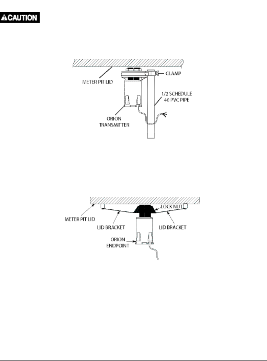
To install, drive rebar or stake into the ground prior to attaching the endpoint to avoid damage. Once in the ground, secure
the mounting bracket on the appropriate rebar or pipe using the enclosed washer, wing nut and hex head bolt provided
with the bracket. Insert the endpoint through the bracket and thread the locking nut to secure the endpoint. For best
results, mount the endpoint approximately 1-2" below the underside of the lid.
Figure 4: Pit ORION Beneath Lid Installation
INTEGRATED PIT HANGER INSTALLATION
ORION endpoints can also be installed in composite and plastic lids with an integrated hanger for AMR-AMI endpoints. An
installation kit for installing an ORION Pit endpoint to the lid is available. To install an ORION endpoint to a composite or
plastic lid, thread the locking ring onto the top of the ORION endpoint. Slide the endpoint into the lid bracket. Thread the
locking nut so that the endpoint is held rmly in place.
Figure 5: Hanger Installation
(12-10) Page 7
ORION® Water Endpoint
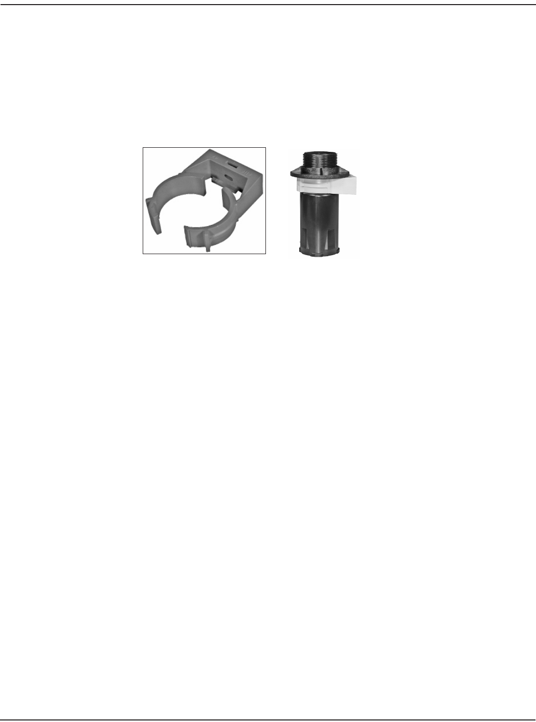
VAULT INSTALLATION OPTION
When installation of the ORION endpoint occurs in a deep vault, Badger Meter oers a kit that can be used to mount the end-
point to the side of the vault. To install, mount the ‘C’ clamp on the side of the vault. Select a location close to the top of the
vault that will not be damaged when access to the meter is required. Place the tape, supplied in the installation kit, around
the endpoint approximately ½” from the top of the endpoint. Thread the locking ring on the endpoint until it makes contact
with the tape. Insert the endpoint into the ‘C’ clamp. Close the ‘C’ clamp and lock it in place so that it closes over the tape and
securely holds the endpoint.
NOTE: ORION radio endpoints perform best with a clear line of sight. Performance varies by installation and lid construction.
C-Clamp
C-Clamp around Transmitter
Figure 6: C-Clamp & Placement
Page 8 (12-10)
Installation Data
REMOTE INSTALLATION
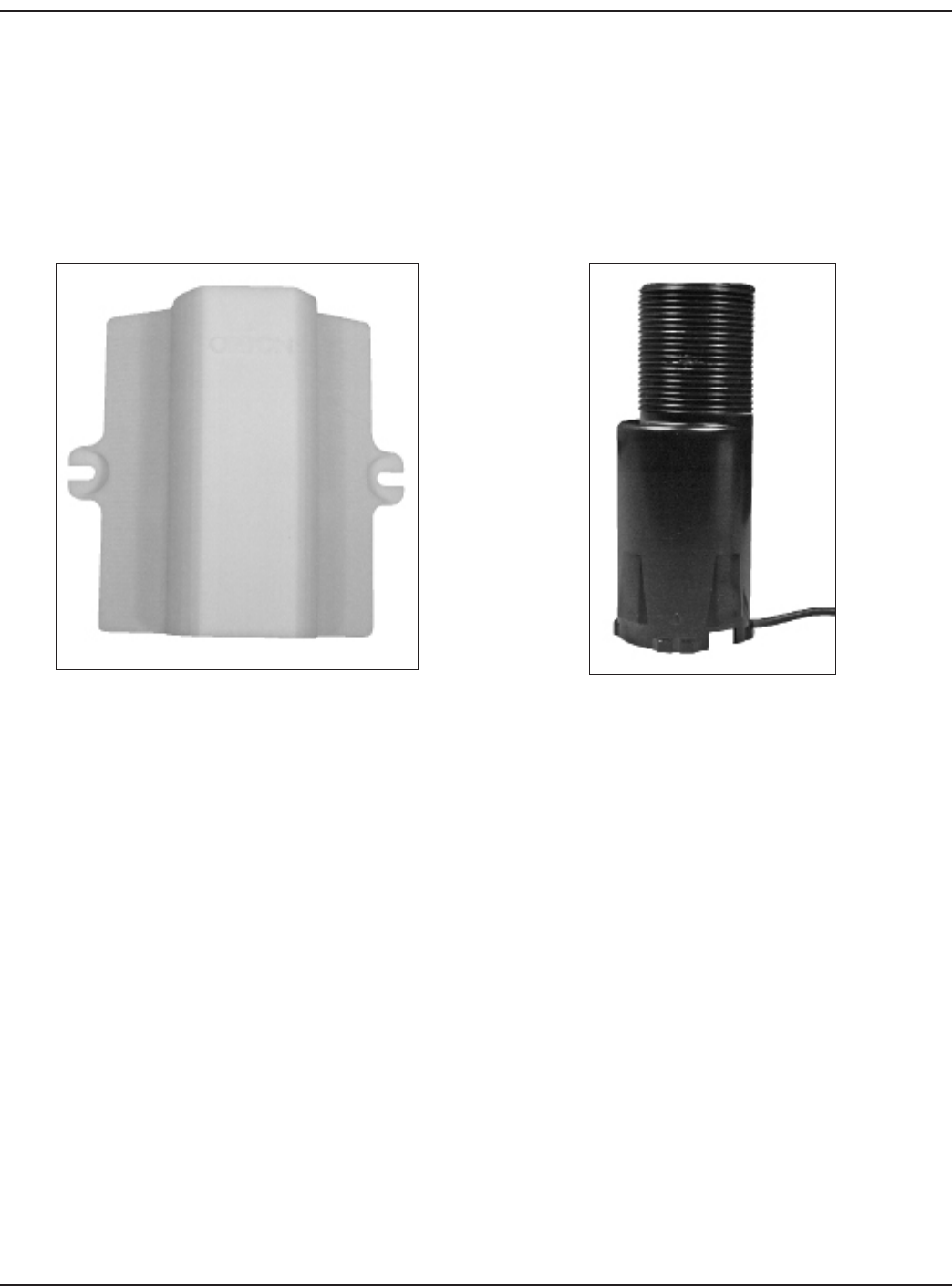
REMOTE BOX ENCLOSURE
The ORION Remote Box Enclosure is for use with either the Recordall® Transmitter Register (RTR®) or Absolute Digital Encoder
(ADE®) stepped tube and threaded tube ORION endpoint for remote mounting applications. The Remote Box Enclosure
is designed for mounting ORION endpoints in indoor or outdoor environments and also provides an environmentally
protected area for gel splice connections (if needed) to be maintained inside the enclosure.
Remote Box Enclosure ORION Endpoint
Figure 7: Enclosure and Endpoint
The following ORION Remote Box Installation Kit (64394-021) is required to properly mount the ORION endpoint for remote
applications.
After obtaining the installation kit, the installer places the endpoint into the ORION Remote Box Enclosure. To ensure
maximum endpoint performance, it is important to mount the ORION endpoint in the proper orientation, with the endpoint
antenna up and ORION endpoint IR communication port and wire down.
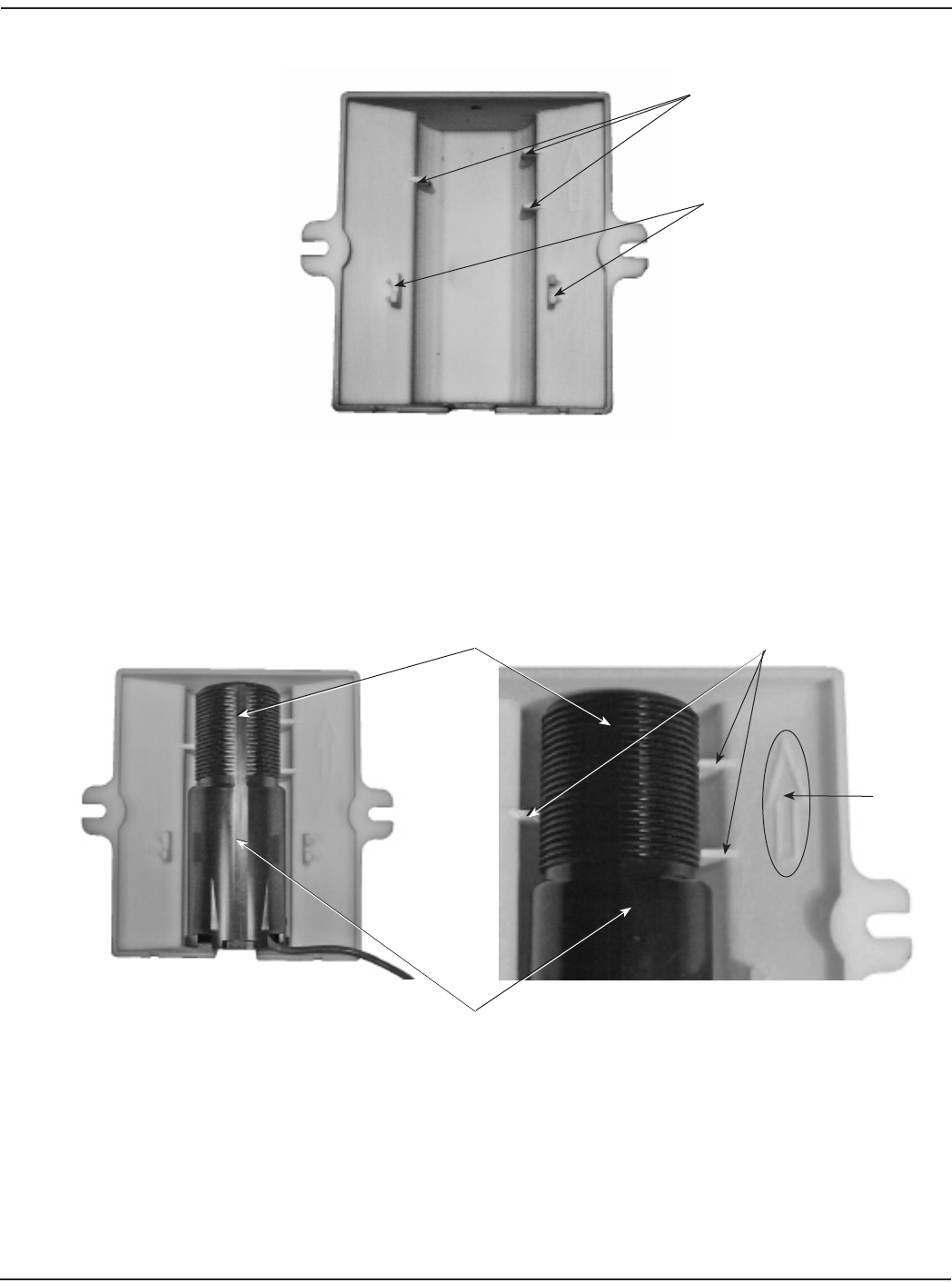
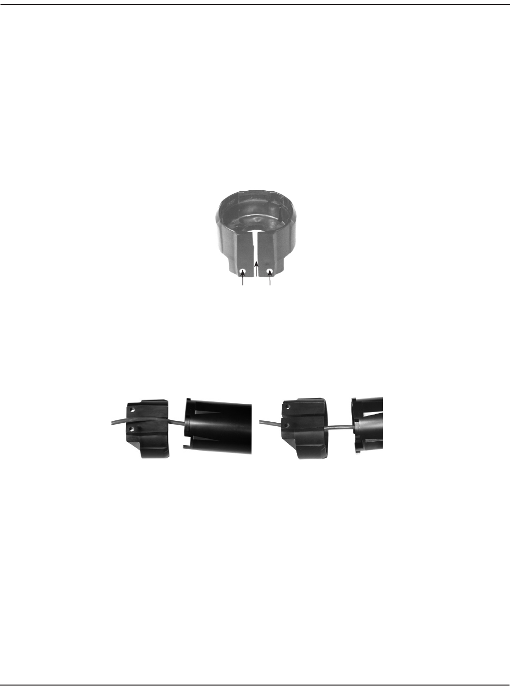
To verify the proper orientation, ip the enclosure over and look inside the ORION Remote Box Enclosure. Locate the three
security ribs inside the Remote Box Enclosure to determine the top of the enclosure. The bottom of the Remote Box Enclo-
sure is identied by the two strain relief tabs located on both sides of the enclosure housing and the hole in the bottom of
the enclosure that allows access to the endpoint IR communication port without having to disassemble the unit (Figure 8 on
page 10).
(12-10) Page 9
ORION® Water Endpoint
Figure 8: Remote Box Enclosure Mounting
When inserting the ORION endpoint into the Remote Box Enclosure, make certain that the at side of the endpoint is facing
the back of the enclosure or toward the installer (Figure 8). When installing, the endpoint antenna must be mounted toward
the top of the enclosure, between the security ribs. Note that the arrow on the back of the Remote Box Enclosure points
up toward the top of the assembly. When installing the Remote Box Enclosure to a wall, it must be mounted with the arrow
pointed up (toward the sky).
Figure 9: Endpoint Orientation
Top 3 Security Ribs
Hole in Bottom
2 Strain Relief Tabs
Transmitter Antenna Security Ribs
Flat Side
Arrow
Page 10 (12-10)
Installation Data
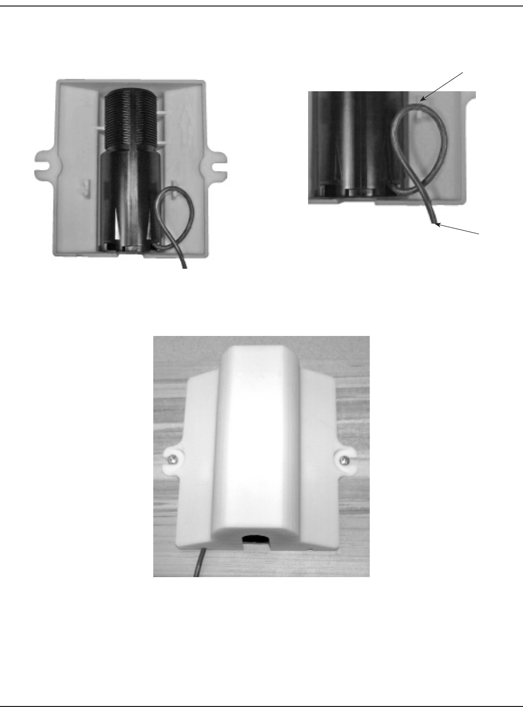
After the endpoint is mounted in the Remote Box Enclosure, loop the endpoint wire through the strain relief tab and through
the cut out on the bottom of the enclosure. If needed, gel splice connections can be made and kept inside the Enclosure prior
to mounting.
Figure 10: Endpoint Wire Positioning
To install, verify that the Remote Box Enclosure is properly positioned with the endpoint antenna up and the endpoint IR port
facing down and secure the enclosure to the wall using appropriate customer supplied screws.
Figure 11: Enclosure Positioning
Right Side
Strain Relief Tab
Cable out of
bottom
(12-10) Page 11
ORION® Water Endpoint
REMOTE BRACKET INSTALLATION
The following instructions are provided to properly install an ORION endpoint in any indoor, outdoor, or pit application. Prior
to beginning the installation procedure, ensure that the following items are available.
• RemoteInstallationBracketKit(RTR®),64394-019orRemoteInstallationBracketKit(ADE®),64394-020
• Twocustomer-suppliedscrews
• Screwdriveranddrill
The Remote Installation Bracket securely mounts an ORION endpoint. For non-submerged indoor and outdoor applications,
the installation bracket can also be used to enclose gel-cap, wire-splice connections to protect them from the environment
and to prevent tampering in any indoor or outdoor non-metallic joist, wall or pit application.
To install the bracket to the housing, follow these steps.
1. Place the encoder cable harness through the slit in the bracket, with the screw holes at the bottom.
Note: Carefully slide the cable harness through the slit in the bracket.
Figure 12: Cable Harness Threading
2. For non-submerged indoor and outdoor applications where splicing is necessary, splice connections together and
wrap any cables inside the base of the housing. Splice connections made in pit environments require a pit eld-splice
kit (xxxxx-xxx), which can be ordered separately.
Slit
Screw Holes
Page 12 (12-10)
Installation Data
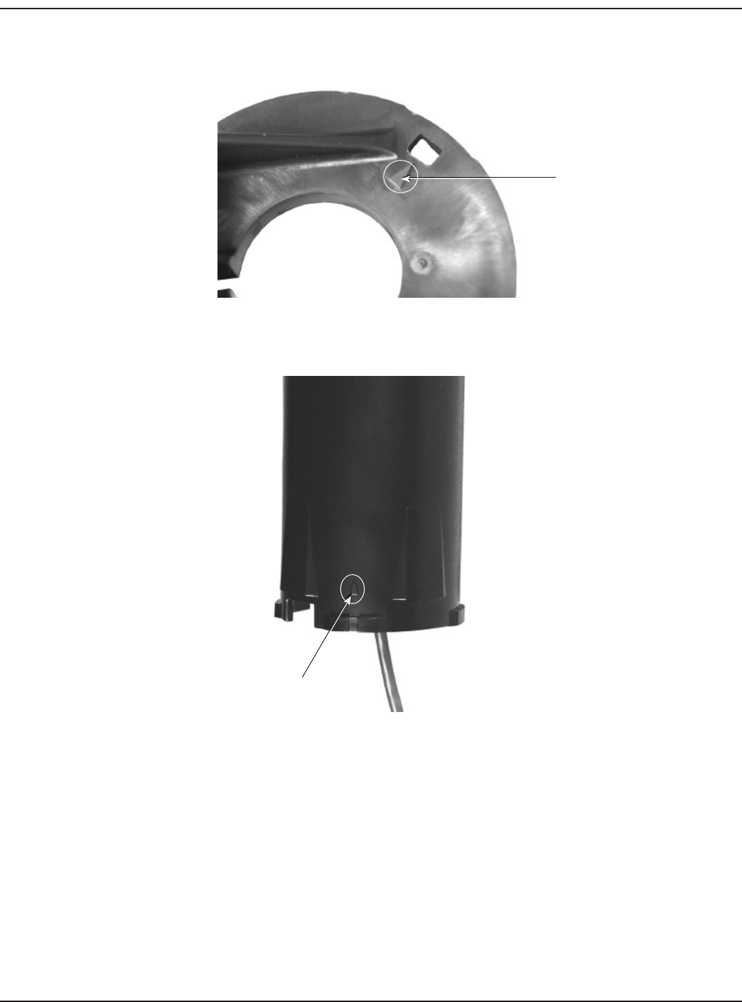
3. On the bottom of the installation bracket there is a small triangle aligned with the small hole. This triangle is used to
properly align the endpoint to the installation bracket.
Figure 13: Aligning Triangle
On the ORION endpoint, there is a small triangle printed on the lower side of the housing.
Figure 14: Housing Triangle
Triangle
Triangle
(12-10) Page 13
ORION® Water Endpoint
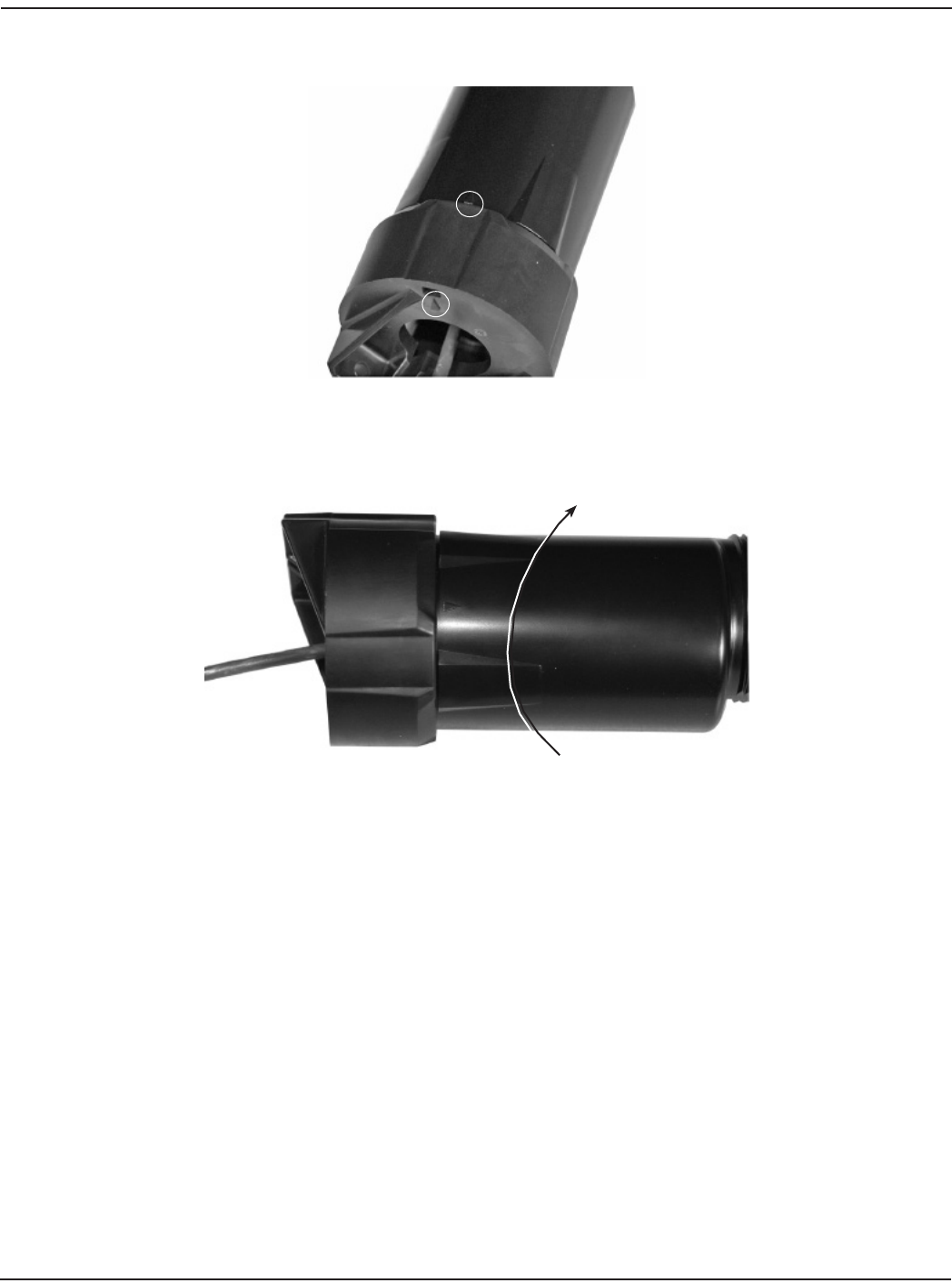
4. Align the two triangles and push the bracket and endpoint together.
Figure 15: Align Both Triangles
5. With the installation bracket in one hand and the housing in your other hand, hold the bracket still and twist the
housing (approximately 1/4 turn), until it clicks and locks into place.
Figure 16: Bracket & Housing Connection
Page 14 (12-10)
Installation Data
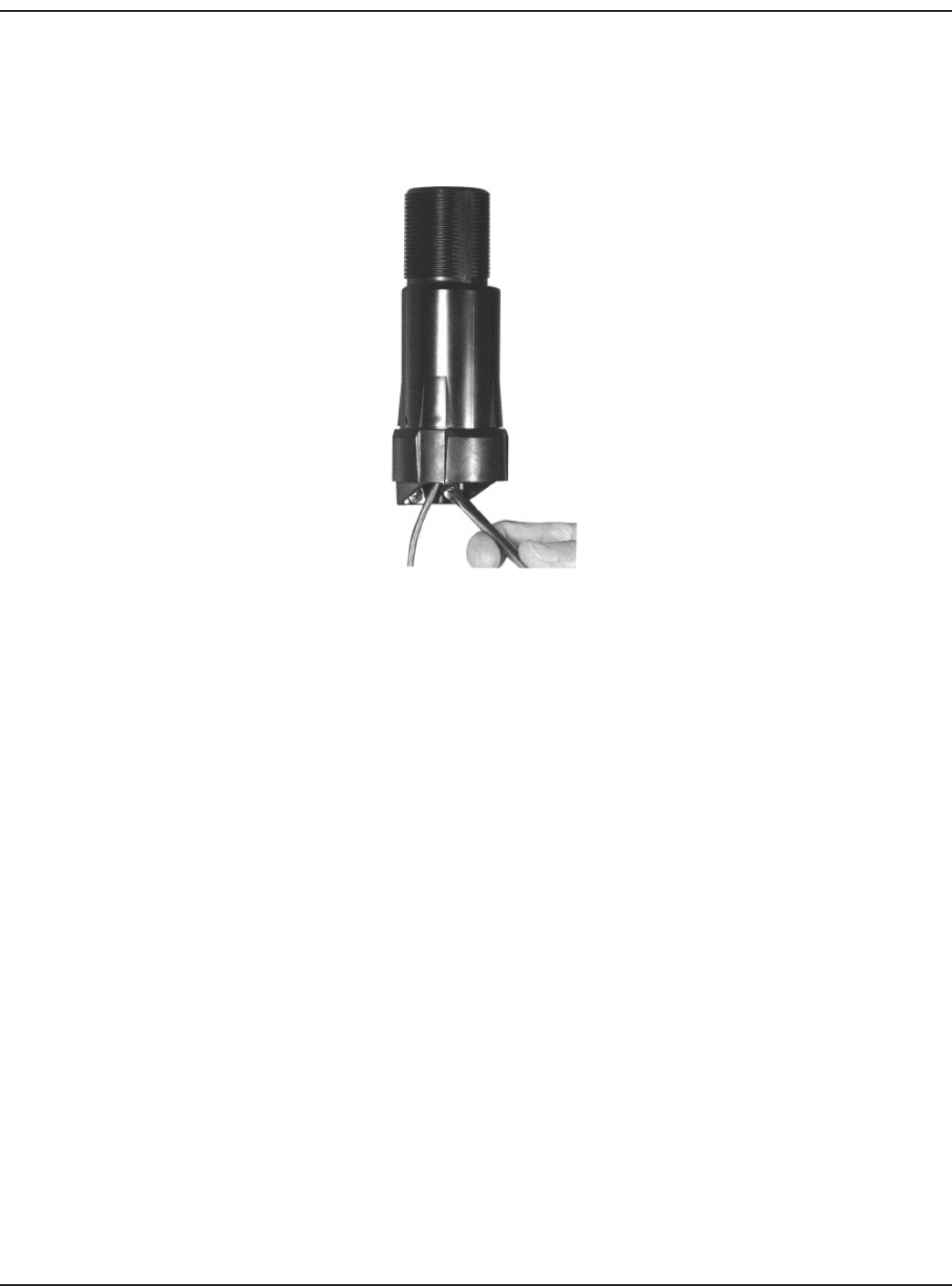
To install the endpoint assembly, follow these steps.
1. Align the ORION endpoint and the installation bracket with the antenna facing upwards (see picture below).
2. Using two customer-supplied screws, secure the endpoint and installation bracket assembly to a
non-metallic joist or wall.
Figure 17: Endpoint Positioning
(12-10) Page 15
ORION® Water Endpoint
WIRING A UNIVERSAL Endpoint
UNIVERSAL Endpoint IDENTIFICATION
The ORION Universal endpoint is available in a three-wire pit or remote endpoint conguration for connection to Sensus®
ICETM and ECR II, Neptune® ProRead and E-Coder™, Elster AMCo ScanCoder®, Hersey® and Metron Translator encoder registers.
All ORION Universal endpoints are shipped from the factory pre-programmed and can be connected to any compatible
encoder. Electronic readings broadcast from the ORION Universal endpoint contain the active number wheels programmed
into the encoder, with a maximum of six digits.
To identify a ORION pit or remote Universal 1 endpoint, ‘Univ’ has been added to the end of the ORION serial number. In addition,
all Universal endpoints are shipped factory programmed in a sleep mode with a standard cable (10 feet for remotes and three
feet for pit applications) for connection to a compatible Sensus, Neptune, Hersey or Elster AMCo® encoder. ORION Universal
endpoints begin broadcasting their readings as soon as they are awakened – either by running consumption through the
encoder it is connected to or by using the infrared communication program on the ORION reading equipment. If the endpoint
is awakened by running consumption, note that it may take several hours for the ORION Universal endpoint to begin
broadcasting. This is due to the ORION Universal endpoint update schedule, which has the endpoint updating its reading
from the encoder once an hour.
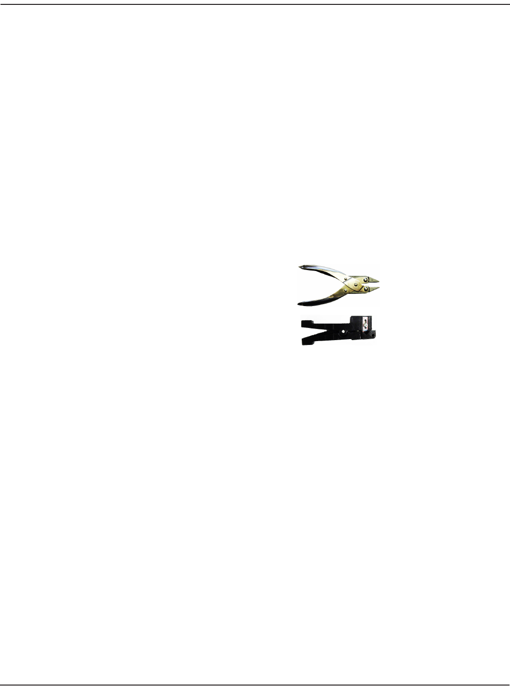
REQUIRED SPLICE TOOLS
59983-001 Gel Splice Crimping Tool
59989-001 Coax Wire Stripper
N/A Wire Cutter
INSTALLATION
Carefully remove the ORION Universal endpoint from the shipping carton and inspect the unit for damage. Retain the
contents of the installation kit for use in mounting and installing the endpoint in the eld.
Wiring the ORION Universal Endpoint to an Encoder
The ORION Universal endpoint is a three-wire metering endpoint device that requires connection to an encoder to complete
the assembly. All three wires must be connected to complete an installation.
The ORION Universal endpoint connection can be made to either existing wires from the encoder or directly to the terminal
screws of the encoder, depending on the application and manufacturer. If making a connection to existing wires use the
installation kit provided and follow the instructions below.
To connect an encoder with existing wires to a ORION Universal endpoint, strip approximately 1 ½ inches of outer insulation
sheath from the encoder and endpoint cables using the stripping tool. We recommend using part number 59989-001 Coax
Stripper. Use caution when removing the outer sheath so that the inner signal wire insulation is not nicked or damaged.
Unwind the outer foil shield from the endpoint cable and cut it o even with the outer sheath using a cutting device.
Page 16 (12-10)
Installation Data
Using the charts below, connect the ORION Universal 1 endpoint to an approved encoder according to the following guide
lines. Verify the endpoint serial number prior to completing the wiring set up.
ORION Endpoints - Serial Number > 80,000,000
Universal 1
Endpoint
Wire
Sensus
ECR II,
ICE
Neptune
ProRead
Elster
AMCo
ScanCoder
AMCO
Invision
ARB-
V**
Metron
Hawkeye
Red R B G G B B
Black B G B B G B
Green G R R R R G
ORION Endpoints - Serial Number < 79,999,999
Universal 1
Endpoint
Wire
Sensus
ECR II,
ICE
Neptune
ProRead
Elster
AMCo
ScanCoder
ARB-V** Metron
Hawkeye
Red R B G R B
Black B G B B B
Green G R R G G
R = Red B = Black G = Green
*Due to the customized, factory wire congurations of the Hersey translator, please contact Badger Meter for proper wiring
guidelines.
**A separate ORION endpoint is available for connectivity to the Neptune ARB-V encoder.
Connect the encoder cable wires to the ORION Universal endpoint wires using the insulation gel connectors provided in the
installation kit. Refer to the chart to determine which wires need to be connected to complete an installation. The ORION
system was designed as a three-wire AMR system.
The ORION system oers connectivity to any of the mechanical/absolute encoder registers listed above, with a manufacture
date between 2000 to the present, as long as the encoder is programmed into the three-wire output mode for AMR and has
three wires connected to it. Encoder registers that are currently in two-wire mode of operation will require programming
by the Utility, including registers that support auto two or three wire detection systems that do not automatically switch to
three-wire mode of operation once a compatible endpoint is connected for ORION connectivity.
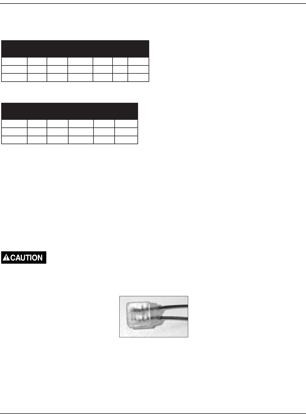
Do not strip any insulation from the ends of the wires before you push them into the connector.
Push the wires that are to be connected together as far as possible into the connector.
Figure 18: Wires In Connector
Using the required Gel Splice Crimping Tool, Badger Meter number 59983-001, place the connector with the wires into the
jaws of the crimping tool.
(12-10) Page 17
ORION® Water Endpoint
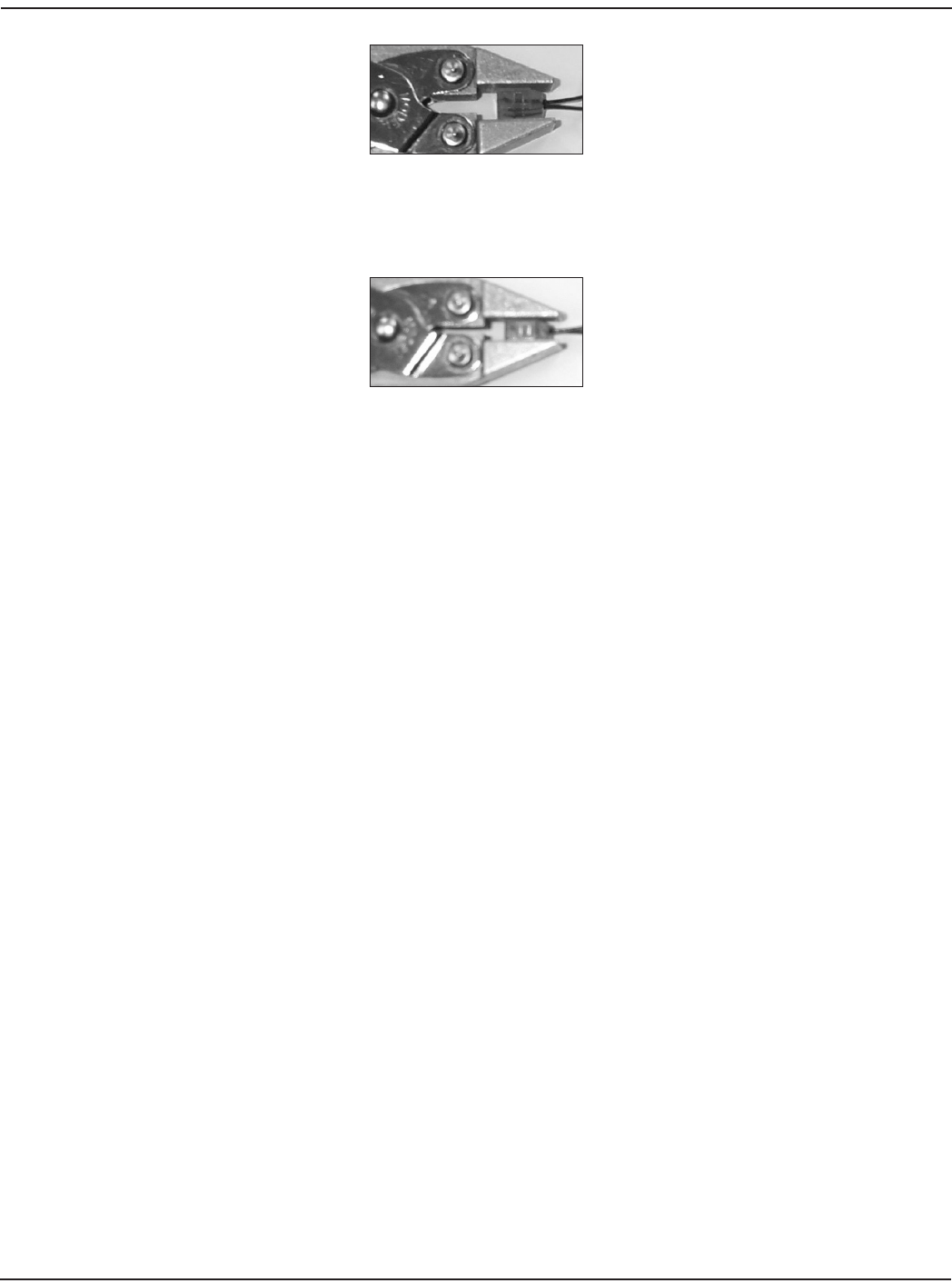
Figure 19: Connector in Crimping Tool
Crimp the connector by squeezing the handles until the connector is completely compressed. The crimp tool is designed to
prevent applying too much pressure to the gel cap. Continue to apply pressure for three seconds.
Figure 20: Compress Connector
Place the two plastic cable ties and tighten securely for strain relief. Remove excess cable tie with the cutting device.
For remote installations, the connection is complete.
For pit installations, place all three connected wires with gel caps into the eld splice tube provided in the installation kit.
Make sure that the wires with gel caps are inserted as far as possible into the eld splice tube. Close the eld splice tube. The
connection is now complete.
Testing the Wire Connections
The connection of the encoder and Badger ORION Universal endpoint can be tested using an ORION data collector. It is
recommended that all wiring connections be tested while on site. To test, set the data collector into the Quick Read function.
ENCODER REGISTER INSTALLATION
Install an RTR® or ADE® on the water meter and secure it using either the Torx® screw or standard seal screw provided.
RTR Endpoint
Once the Pit ORION endpoint is securely installed and the RTR is mounted on the water meter, the ORION system is ready for
operation. Run water through the meter to increment the RTR 1/10th of the test circle. Upon receiving the rst digital signal
from the RTR, the transmitter counts the signal and begins its radio frequency transmissions. No specic testing of the wiring
or programming of the transmitter is required. Reading each pit transmitter immediately after installation veries proper
operation and reading performance. ORION reading equipment only can be used to read installed ORION endpoints.
ADE Transmitter
Once the ADE is assembled to the meter and the ORION endpoint is installed, the endpoint is ready for operation. The
user can either let the endpoint automatically turn itself on by rolling the ADE number wheels to all zeros or by turning
on the endpoint with the handheld or mobile reading equipment. Since the ADE endpoint updates its reading from the
ADE once an hour, it may take up to one hour after the ADE number wheel stack rolls to all zeros for the endpoint to begin
broadcasting. In either case, no specic testing or programming of the endpoint is required. Reading each pit endpoint after
it has been installed veries proper installation and reading performance.
Page 18 (12-10)

Installation Data
LICENSE REQUIREMENTS
This device complies with Part 15 of FCC Rules. Operation of this device is subject to the following conditions: (1) This device
may not cause harmful interference, and (2) this device must accept any interference received, including interference that
may cause undesired operation.
No FCC license is required by a utility to operate a Badger® ORION® meter reading system.
Any changes made, but not approved by Badger Meter, can void the user’s authority to operate the equipment.
In accordance with FCC Regulations, “Code of Federal Regulations” Title 47, Part 2, Subpart J, Section 1091, transmitters pass
the requirements pertaining to RF radiation exposure. However, to avoid public exposure in excess of limits for general
population (uncontrolled exposure), a 20 CM distance between the transmitter and the body of the user must be maintained
during testing.
(12-10) Page 19

Due to continuous research, product improvements
and enhancements, Badger Meter reserves the right
to change product or system specications without
notice, except to the extent an outstanding contractual
obligation exists.
Badger Meter | P.O. Box 245036, Milwaukee, Wisconsin 53224-9536
800-876-3837 | infocentral@badgermeter.com | www.badgermeter.com
ORION® is a registered trademarks of Badger Meter, Inc.
Copyright 2010 Badger Meter, Inc. All rights reserved.