Badger Meter 4545 direct sequence spread spectrum transmitter and an User Manual Installation Manual
Badger Meter Inc direct sequence spread spectrum transmitter and an Installation Manual
Installation Procedure

Recommended Installation Procedure:
(for pit lid installation)
1.
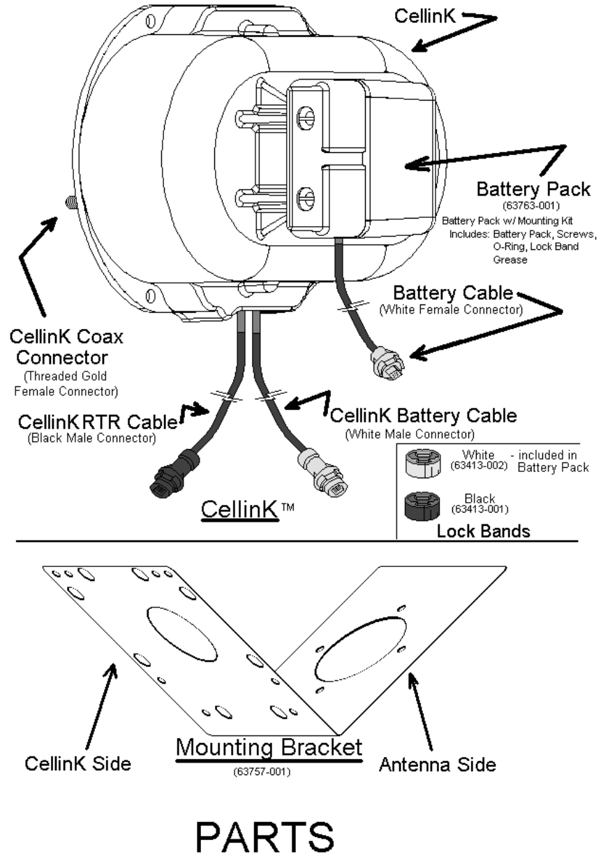
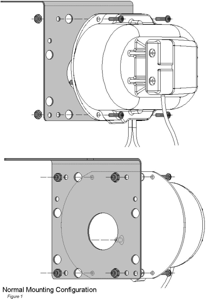
Using the four machine screws and lock-nuts with the nylon inserts provided, attach
CellinK™ to CellinK side of Mounting Bracket. Ensure to mount CellinK as space
allows, either normal position or 90º offset.
(See Fig 1 for normal mounting or Fig 2 for 90
°
offset mounting)
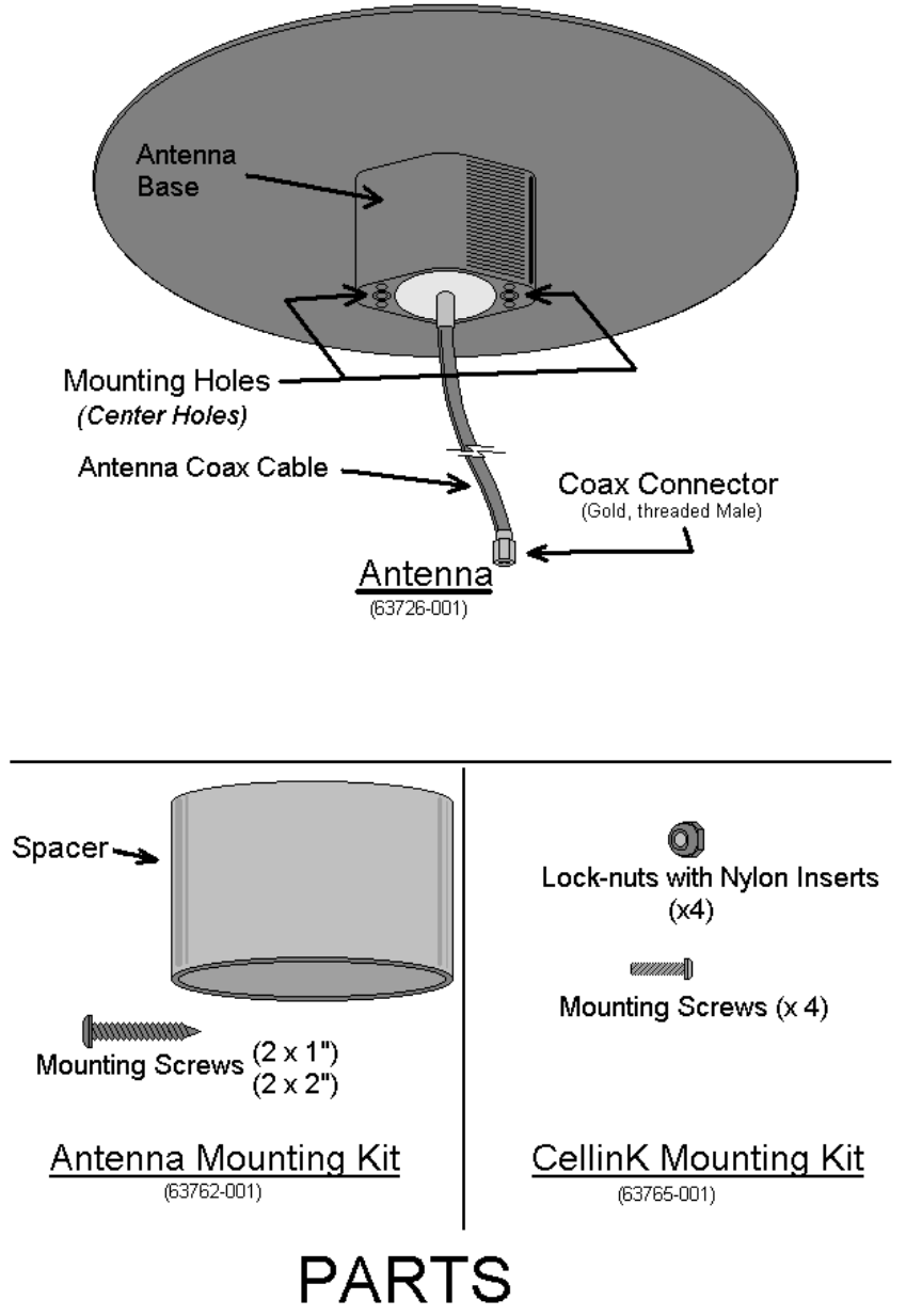
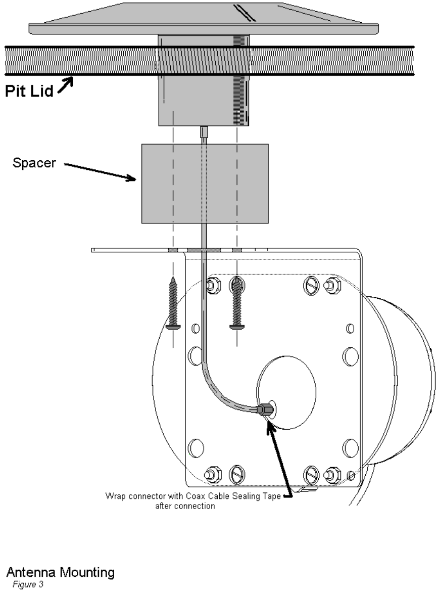
2. Insert Antenna Coax Cable and Antenna Base through pre-drilled hole in Pit Lid.
(See Fig 3)
3. Slide Spacer over Antenna Coax Cable and Antenna Base.
(See Fig 3)
4. Feed Antenna Coax Cable through center hole on Antenna side of Mounting Bracket
and, using the two Antenna Mounting screws provided, attach Mounting Bracket to
Antenna Base. Ensure that Antenna Mounting Screws are fed into the CENTER
holes on Antenna Base. Also, ensure that Mounting Bracket is positioned as to allow
for proper clearance between the CellinK and the Pit wall, Meter/RTR, and other pit
contents.
(See Fig 3)
5. Connect Antenna Coax Cable to CellinK Coax connector and wrap with Coax Cable
Sealing Tape. Ensure to cover all exposed metal of Coax connector and compress
tape tightly to provide proper water-proofing.
(See Fig 3)
6. Connect RTR cable to CellinK RTR Cable (Black Connector).
(See Cable Connecting Procedure)
7. Connect Battery cable to CellinK Battery Cable (White Connector).
(See Cable Connecting Procedure)
8. Mount RTR to Meter Body and secure in place with seal screw.
9. Return pit lid to pit. Ensure all pit contents have proper clearance - no equipment
should be “forced” into position. Also, ensure no cables are pinched between lid and
pit.
FCC ID: GIF4545
This device complies with Part 15 of the FCC Rules. Operation is
subject to the following two conditions: (1) This device may not cause
harmful interference, and (2) this device must accept any interference
received, including interference that may cause undesired operation
!WARNING!
Any modifications to the unit, unless expressly approved by the party responsible
for compliance, could void the user’s authority to operate the equipment.
This product is intended to be installed, operated, and used only by properly trained
professionals, in accordance with FCC rules and regulations.
2
3
4

5
6
7
Cable Connector Procedure
Installation Instructions:
The following instructions are to assist you in the connection process if necessary. Keep all parts clean
prior to assembly. Any dirt or water within the connector enclosure can cause corrosion of the contacts
which will reduce connector life.
When connecting the components, ensure the terminal
cavity of the Male Connector contains an ample amount of
grease. The connectors should be shipped from the
factory with the appropriate quantity, but if the
connectors are being replaced or repaired, some volume of
grease may have been displaced. In that case, or if the
connector was inadvertently shipped without grease, then
before connecting first apply grease from the small tube
in the kit into the terminal cavity for the male
connector. The tube contains the correct quantity of
grease to use, so be sure to dispense all of it into the
connector. A pliers may be helpful to assist in
squeezing out the last quantity of grease.
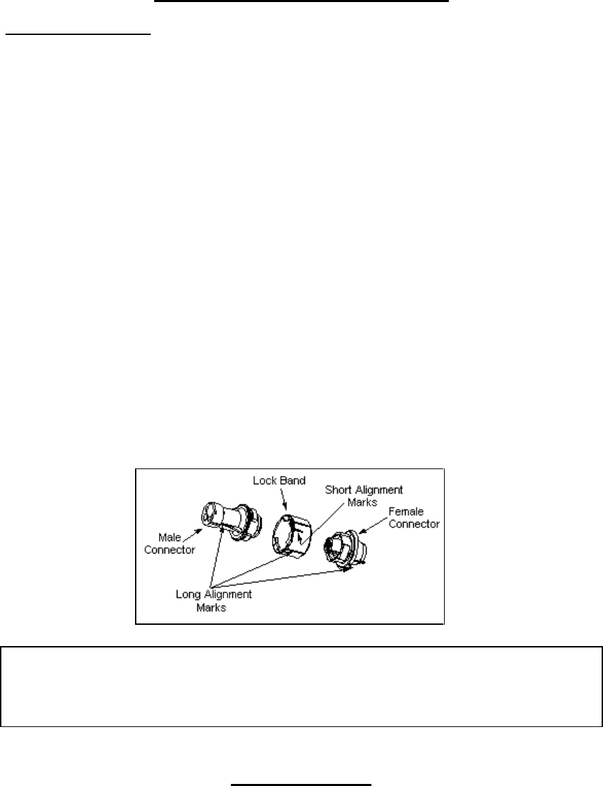
1. Drop the Lock Band onto the Female Connector with the Short Alignment Mark up and position the
band so that the Long Alignment Mark is lined up with the Alignment Mark at the base of the Female
Connector.
2. Insert the Male Connector into the female connector, again lining up the Long Alignment Marks on
each component. The insertion operation may require significant force to displace the excess grease
from the connector cavity.
3. With the connector halves forced together, turn the locking band to align its Short Alignment Mark
with the Long Alignment Marks on the connector halves. It may require a pliers to rotate the band to
its final position. A clicking sound should be heard when the band achieves its final and correct
position.
FCC ID: GIF4545
This device complies with Part 15 of the FCC Rules. Operation is
subject to the following two conditions: (1) This device may not cause
harmful interference, and (2) this device must accept any interference
received, including interference that may cause undesired operation
!WARNING!
Any modifications to the unit, unless expressly approved by the party responsible
for compliance, could void the user’s authority to operate the equipment.
8
This product is intended to be installed, operated, and used only by properly trained
professionals, in accordance with FCC rules and regulations.