Baicells Technologies CW0100 LTE Outdoor CPE User Manual BaiCells CW0100 CPE Installation Guide
Baicells Technologies Co., Ltd. LTE Outdoor CPE BaiCells CW0100 CPE Installation Guide
Contents
- 1. User Manual
- 2. Users Manual
User Manual

All rights reserved © BaiCells Technologies Co., Ltd.
BaiCells CW0100 CPE Installation Guide
V1.0
1
About This Document
This document introduces the installation and debugging steps of CW0100 outdoor
CPE equipment, which is used for guiding installer to install CPE correctly.
Copyright Notice
BaiCells copyrights this specification. No part of this specification may be reproduced in
any form or means, without the prior written consent of BaiCells.
Disclaimer
This specification is preliminary and is subject to change at any time without notice.
BaiCells assumes no responsibility for any errors contained herein. For more information,
please consult our technical engineers.
Revision Record
Date
Version
Description
Author
30 Jun,2016
V1.0
Initial released.
Tang Houcheng
Contact Us
E-mail: support@baicells.com
Phone: 86-10-62607100
Website: http://www.baicells.com/

Contents
1. Installation Preparation ................................................................................................. 2
Out-of-Box Audit ...................................................................................................... 2 1.1
Installation Accessories .............................................................................................. 2 1.2
Installation Tools ...................................................................................................... 3 1.3
Installation Environment ............................................................................................ 4 1.4
Safety Protection ........................................................................................................ 4 1.5
2. Equipment Installation ................................................................................................... 5
Appearance ............................................................................................................... 5 2.1
Interface and Button .................................................................................................. 5 2.2
LED Indicators ............................................................................................................. 6 2.3
RF Specifications ......................................................................................................... 6 2.4
Install on Pole ............................................................................................................. 7 2.5
Install on Wall ............................................................................................................. 8 2.6
3. Wire Connection ............................................................................................................. 9
Make Ethernet Cable Connector ............................................................................. 9 3.1
Connect Ethernet Cable ......................................................................................... 13 3.2
Power On .................................................................................................................. 14 3.3
Lightning Protection of Cable ................................................................................... 15 3.4
4. Power on Detection ...................................................................................................... 16
Detection Item ........................................................................................................ 16 4.1
Ethernet Port Working Status .................................................................................. 16 4.2
CPE Configuration Check .......................................................................................... 16 4.3
CPE Access Test ........................................................................................................ 16 4.4
CPE Parameter Record ............................................................................................. 16 4.5
5. Regulatory Compliance ................................................................................................ 17
FAQ ............................................................................................................... 19 Appendix A

Contents of Figure
Figure 2-1 Appearance of CW0100 .............................................................................. 5
Figure 2-2 Install on pole A ........................................................................................... 7
Figure 2-3 Install on pole B .......................................................................................... 8
Figure 2-4 Mounting Hole of Install on Wall ................................................................. 8
Figure 3-1 Strip Shielded Twisted Pair ......................................................................... 9
Figure 3-2 Separate the metal net, wire of cable and aluminum foil layer .................. 9
Figure 3-3 Cut off the aluminum foil layer of twisted pair ........................................... 10
Figure 3-4 Color Order ............................................................................................... 10
Figure 3-5 Insert the twisted pair core into line card .................................................. 10
Figure 3-6 Insert line card into Connector .................................................................. 11
Figure 3-7 Crimping connector ................................................................................... 11
Figure 3-8 Impact the connector with cable shield layer ............................................ 11
Figure 3-9 Cut off the redundant part ......................................................................... 12
Figure 3-10 Completion of shielded connector .......................................................... 12
Figure 3-11 Connect Cable 1 ..................................................................................... 13
Figure 3-12 Connect Cable 2 ..................................................................................... 14
Figure 3-13 POE power Mode .................................................................................... 15

Contents of Table
Table 2-1 CW0100 Interface and button ...................................................................... 5
Table 2-2 LED Indicators .............................................................................................. 6
Table 2-3 RF Specification ........................................................................................... 6
Table 3-1 Lightning Protection Demand of Cable ...................................................... 15
2
1. Installation Preparation
Out-of-Box Audit 1.1
Before opening the box, make sure the packaging cases are in good condition,
undamaged and not soaked. During the unpacking, avoid potential damaging impacts
from hits or excessive force.
Check whether the material in the box is consistent with “Shipping List” and is in good
condition and undamaged.
Note:
During the unpacking, if the outer package is damaged or soaked, stop unpacking and find the cause.
Report the issue to the vendor. For any shortage, miscarriage, or damage is identified, report the local
vendor within 10 days.
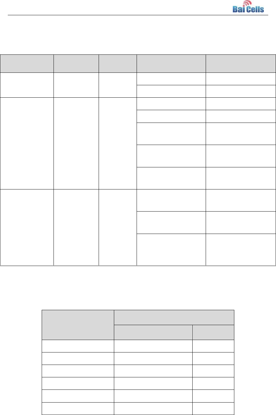
Installation Accessories 1.2
Figure
Name
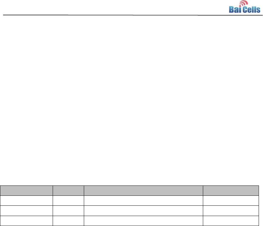
Shielded RJ-45 connector and
line card
POE power adaptor
3
Figure
Name
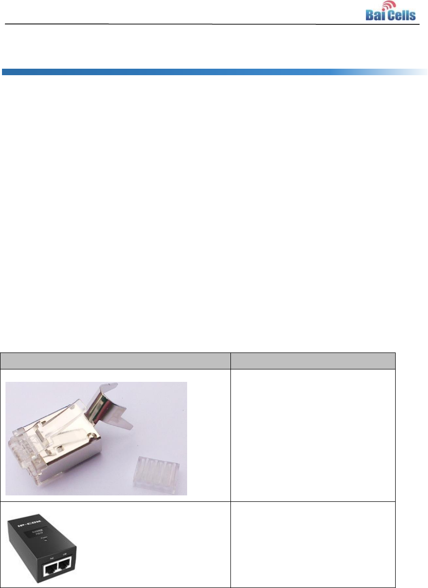
Shielded CAT5 twisted pair
The length of the cable is tailored
according situation of the
installation site.
Plastic tie
Grounding wire
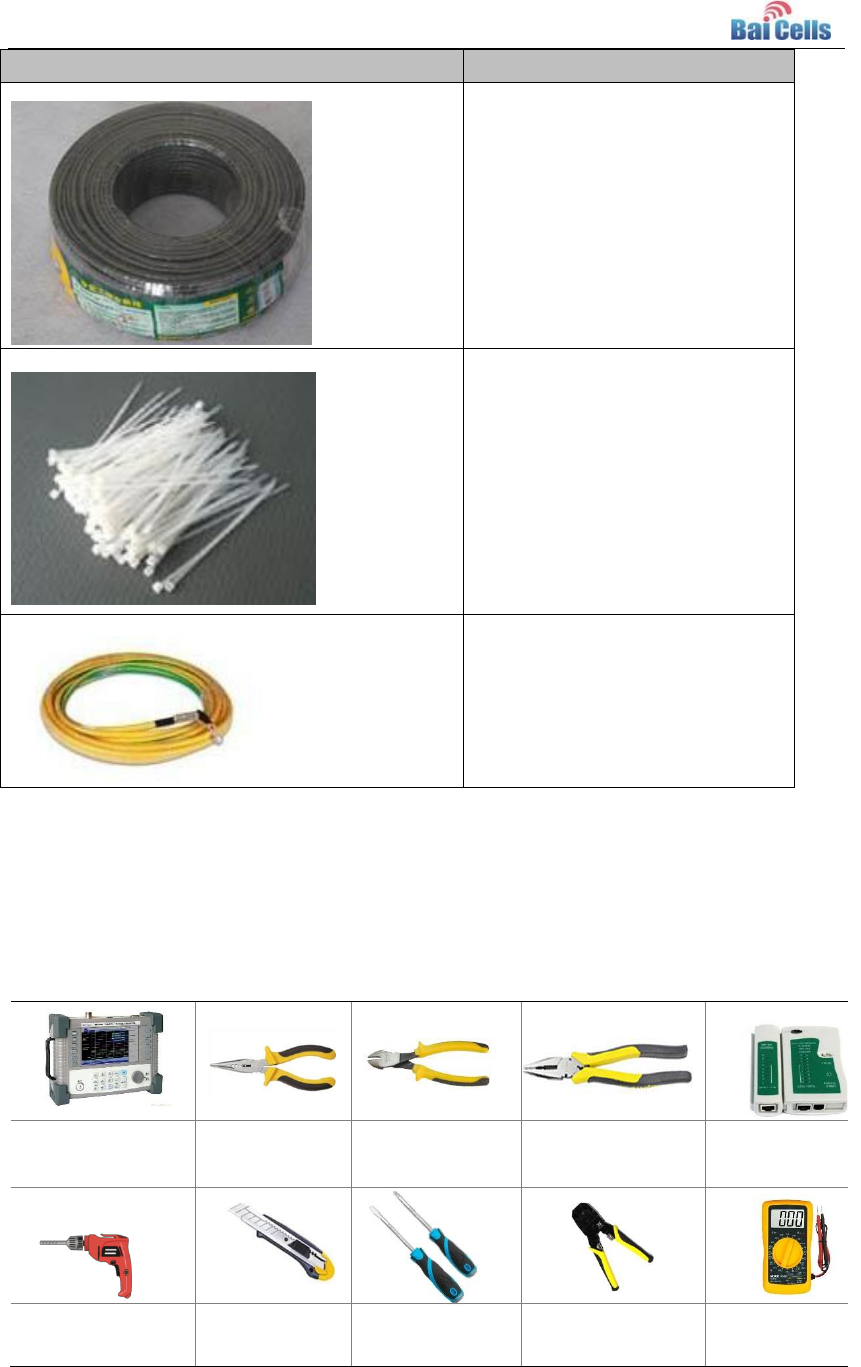
Installation Tools 1.3
The following tools are needed during the installation.
Standing wave
measuring
instrument
Nipper pliers
Diagonal pliers
Pincer pliers
Ethernet cable
tester
Percussion drill
and some drill
heads
Tool knife
Screwdriver
Crimping tool
Multimeter

4
Wrench
Electroprobe
Electric soldering
iron
Ladder
Installation Environment 1.4
According to “Reconnaissance Report”, check whether the external environment of
installation site is ready.
Safety Protection 1.5
Construction personnel must conform to “Construction Safety Specification”, wearing
safety protection guard, such as safety belt, safety helmet, gloves, and wrist strap, and so
on.
5
2. Equipment Installation
Appearance 2.1
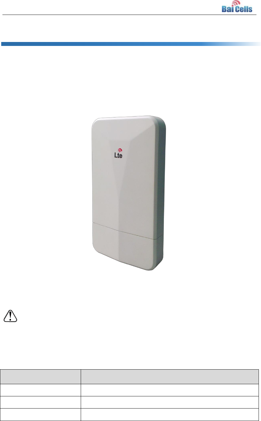
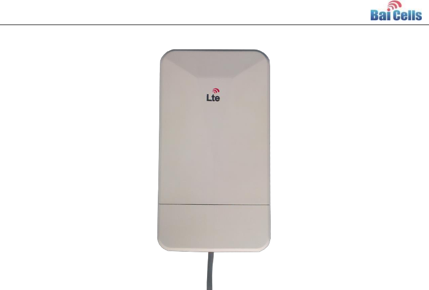
The appearance of CW0100 outdoor CPE is smart, the dimension of CPE is 245mm x
135mm x 42mm, the weights of CPE is 600g. The appearance is shown in Figure 2-1.
Figure 2-1 Appearance of CW0100
CW0100 CPE support installing on pole or installing on wall. The following introduces the
two ways separately.
Caution: The direction of CPE cable exit end must be down.
Interface and Button 2.2
Table 2-1 CW0100 Interface and button
Connectors
Description
ETH RJ45
One LAN
USIM Slot
Support 1.8V/3.0V USIM
Restore Button
Long press over 10s to restore the factory settings
6
LED Indicators 2.3
Table 2-2 LED Indicators
LED Name
Description
Color
LED Behavior
Status Indicator
PWR
Power
Indicator
Green
OFF
No Power Supply
Steady On
Power On
LTE Signal
3 LTEs,
Indicate
connection
state and
signal
strength
Green
All OFF
No Connected
ALL blanking
Connecting
One LED Steady On
Connected, the signal
is weak
Two LED Steady On
Connected, the signal
is medium
Three LED Steady
On
Connected, the signal
is strong
LAN
Eth
Indication
Green
OFF
Ethernet connection
is not established
Steady On
Ethernet connection
is normal
Blanking
Ethernet interface
data being
transmitted
RF Specifications 2.4
Table 2-3 RF Specification
Feature
Capability
Value
Unit
Mode
TDD
Channel Bandwidth
5/10/15/20
MHz
Max Output Power
24
dBm
LTE Standard
3GPP R9
Frequency
3650 ~ 3700
MHz
Antenna Gain
11
dBi
7
Install on Pole 2.5
Installing on pole have three methods: traditional on pole, telegraph on pole and iron on
tower.
Traditional on pole: Required diameter of the pole is 25mm to 45mm.
Telegraph on pole: If the pole is telegraph, you need to install a pole that length is
over 700mm and diameter is 25mm to 45mm as the mounting bracket.
Iron on tower: If CPE is installed on iron tower, you need to choose vertical direction
angle iron as the mounting bracket. The length is about 25mm to 45mm.
Installation steps is as follows:
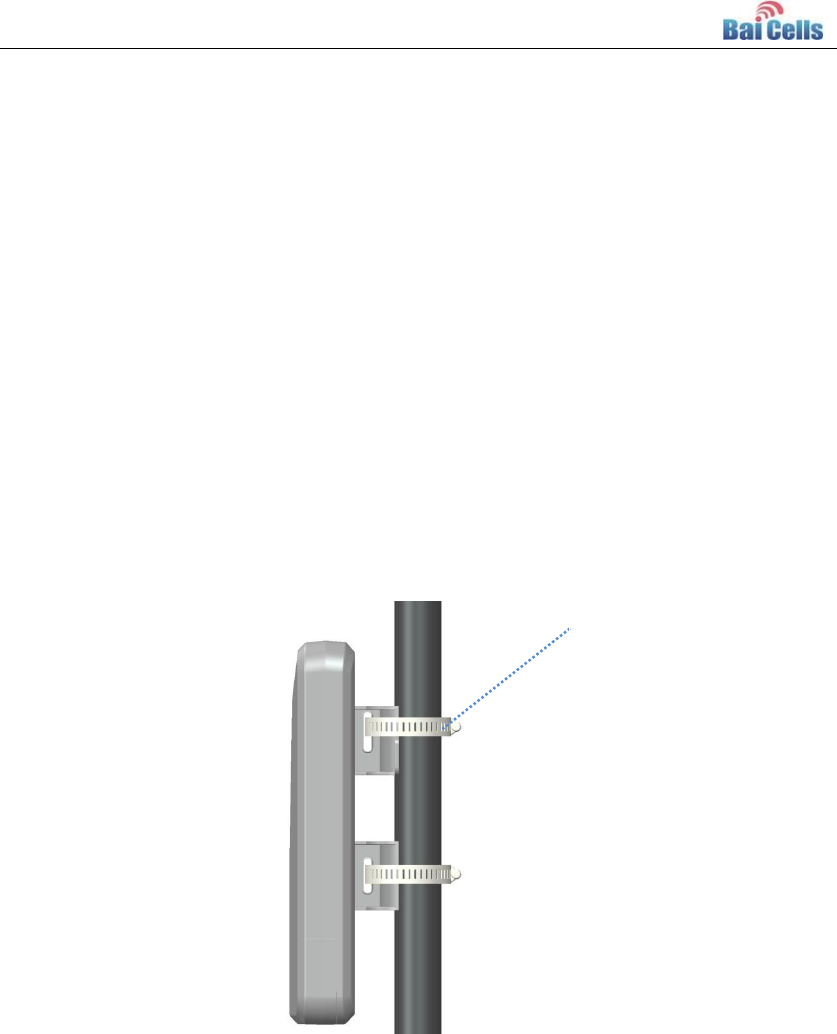
1. Loosen iron hold hoop use the screw driver, make the hold hoop through the
mounting hole and fix with the pole.
Figure 2-2 Install on pole A
2. Locking the iron hold hoop use screw driver, fasten the CPE with the pole.
Iron hold hoop
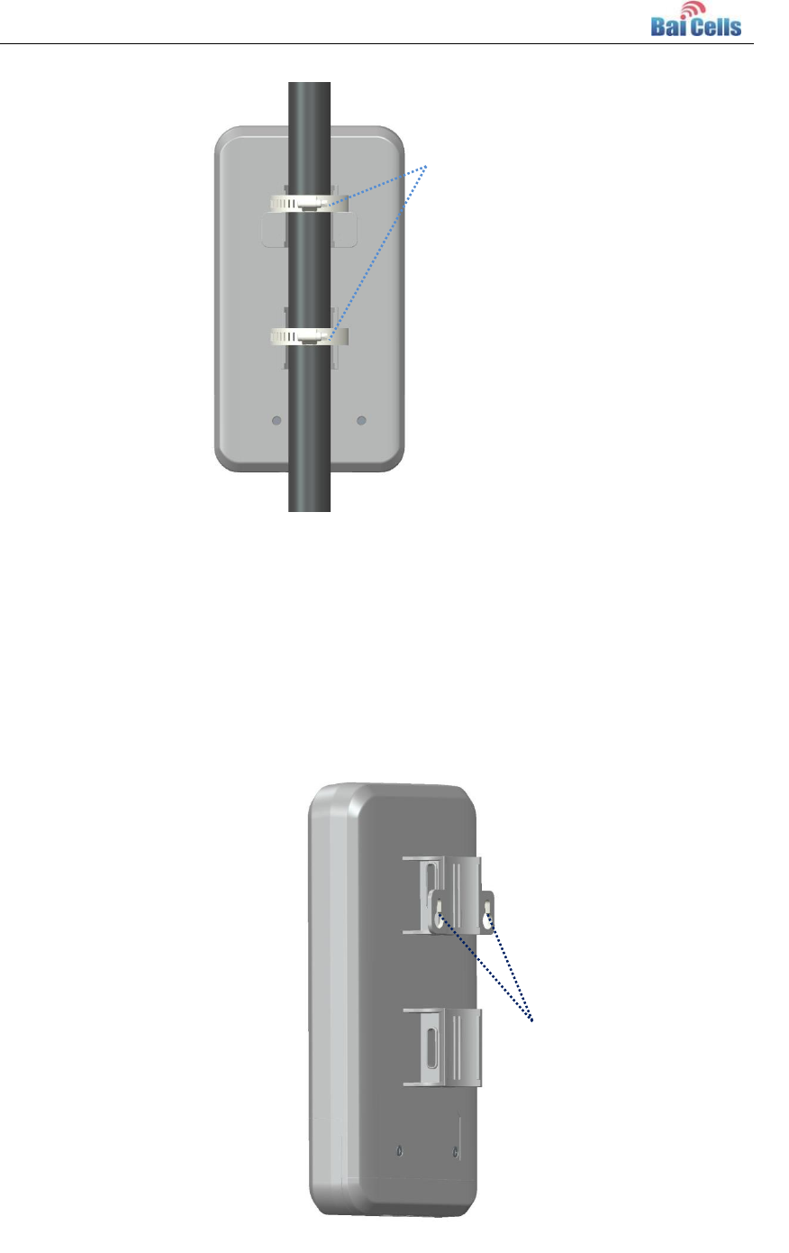
8
Figure 2-3 Install on pole B
Install on Wall 2.6
When CW0100 installs on wall, the installation method is as follows:
On the wall, fix two big head screw which distance is 52mm, and then hang the CPE on
the big head screw.
Figure 2-4 Mounting Hole of Install on Wall
Fasten the screw
using screw driver
Mounting hole
of install on wall
9
3. Wire Connection
Make Ethernet Cable Connector 3.1
CW0100 outdoor CPE need to use shielded CAT5 twisted pair, the operation steps of
making connector is as follows::
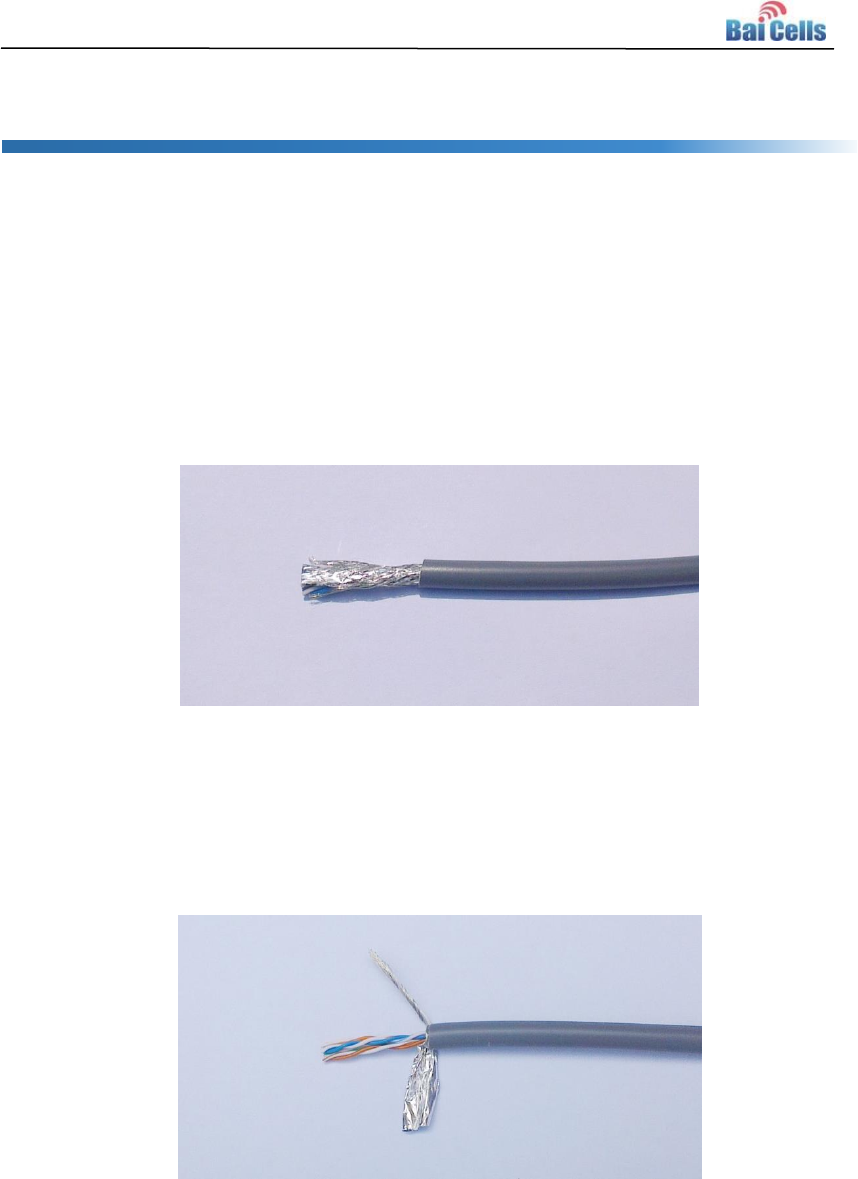
1. Before making the RJ-45 shielded connector, strip the outer Jacket of the twisted pair
about 30mm using crimping tool, which is shown in Figure 3-1.
Figure 3-1 Strip Shielded Twisted Pair
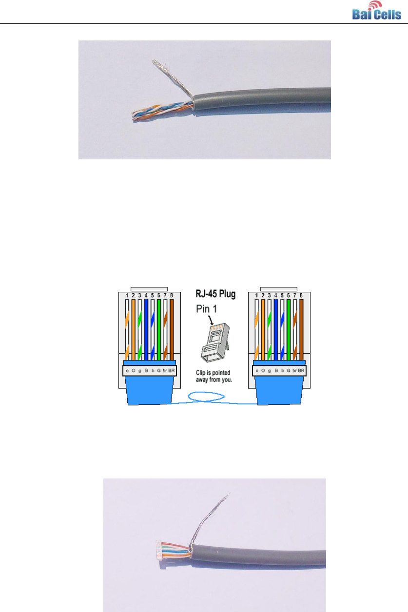
2. Separate the metal net, wire of cable and aluminum foil layer of twisted pair, as
shown in Figure 3-2.
Figure 3-2 Separate the metal net, wire of cable and aluminum foil layer
3. Cut off the aluminum foil layer of twisted pair using diagonal pliers, as shown in
Figure 3-3.
10
Figure 3-3 Cut off the aluminum foil layer of twisted pair
4. The mode of connection is standard straight through cable. The color order is
white/orange, orange, white/green, blue, white/blue, green, white/brown, brown,
which is shown in Figure 3-4. The color order is important to get corrected.
Figure 3-4 Color Order
5. Insert the eight wires into the line card according to the color order, shorten them to a
suitable length (about 12 mm) using diagonal pliers, as shown in Figure 3-5.
Figure 3-5 Insert the twisted pair core into line card
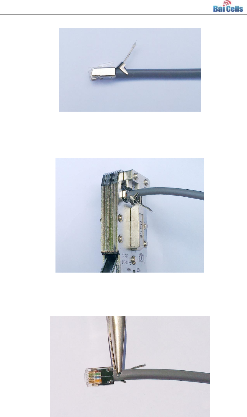
6. Insert the line card having passed through eight wires into shielded connector, ensure
that the wires go to the end. The line card that one side is plane, the other side is
convex, ensure that the shielded connector match with the line card, as shown in
Figure 3-6.
11
Figure 3-6 Insert line card into Connector
7. Crimping the cable using crimper, as shown in Figure 3-7.
Figure 3-7 Crimping connector
8. Impact the metal part of the shielded connector tail with the metal net shielded layer
of the Ethernet cable using nipper pliers, as shown in Figure 3-8.
Figure 3-8 Impact the connector with cable shield layer
12
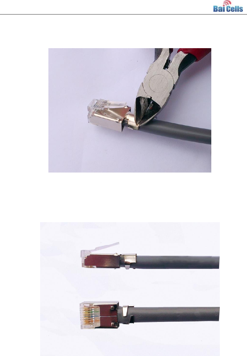
9. Cut off the redundant part of metal net using diagonal pliers, as shown in Figure 3-9.
Figure 3-9 Cut off the redundant part
10. After the completion of shielded connector making, as shown in Figure 3-10.
Repeat all the steps and wire color on the other end of the cable.
Figure 3-10 Completion of shielded connector
11. Test whether the cable is normal using Ethernet cable tester.
After the completion of two ends making, use Ethernet cable tester to test whether it
13
is normal. In the tester, if eight signal indicator and grounding indicator flash green in
turn, it indicates that the Ethernet cable is normal. If any signal indicator is red or
yellow, it indicates that there is circuit break or bad contact. You need to make a new
connector again.
Connect Ethernet Cable 3.2
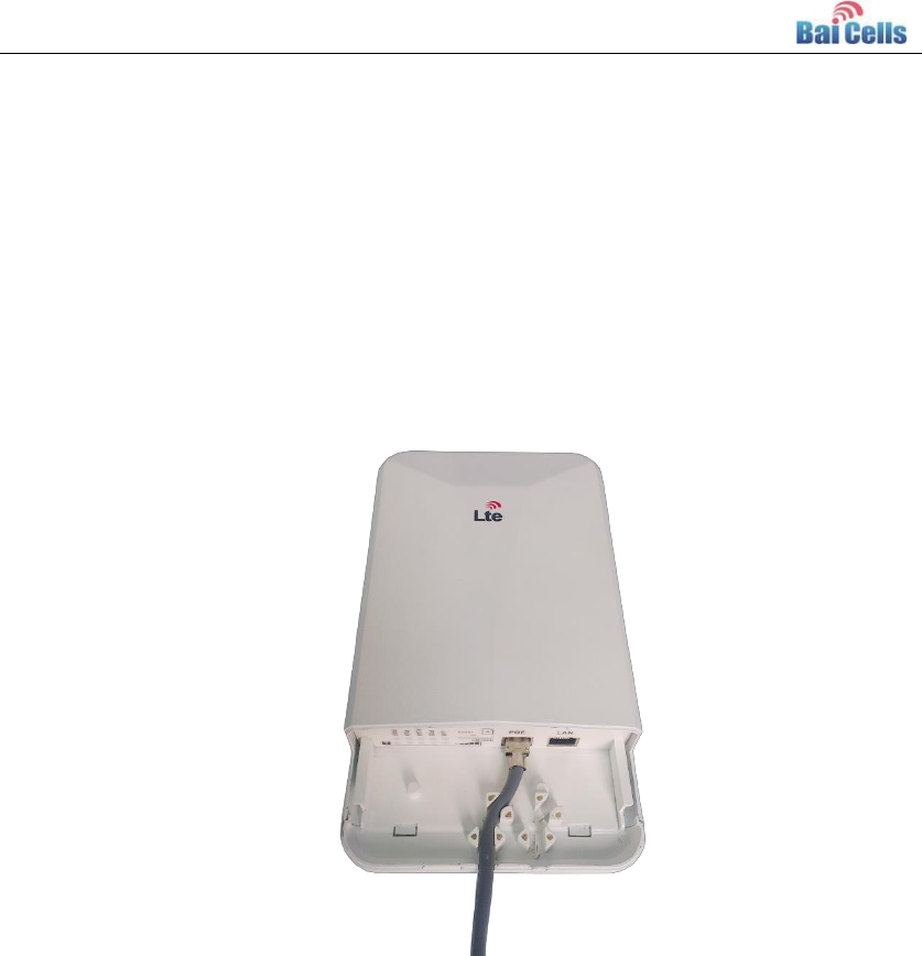
1. Connect the shielded cable to WAN interface of CPE, as shown in Figure 3-11.
Figure 3-11 Connect Cable 1
2. After connecting the Ethernet cable, cover the slide of CPE, as shown in Figure 3-12.
14
Figure 3-12 Connect Cable 2
3. Connect to POE power.
One end of the cable connect to CPE and the other end connect to POE power. Fix
the cable on the pole using plastic tie close to CPE about 20cm, preventing the
damage of the cable waggling with the wind.
It is recommended that the cable is fixed by plastic tie at intervals of 50cm until POE
power. If the length of outdoor is too long, you need to protect the cable with metal
shielded flexible sleeve.
Power On 3.3
CW0100 outdoor CPE is powered with POE. CPE provides standard POE power interface
conformed to IEEE 802.3af standard. The 4, 5 (+), 7, 8 (-) wire have direct current. Before
power on, test whether there is voltage output and whether voltage output is inverse with
multimeter.
Power on CW0100 CPE with POE supply:
1. Connect DATA IN port of POE adaptor to one of a switch port with Ethernet cable.
2. Connect one end of grounding wire to PE terminal of POE adaptor and fasten it, the
other end of grounding wire connect to grounding device.
3. Connect DATA&POWER OUT port of POE adaptor to POE port of CW0100 with
Ethernet cable.
Place POE adaptor and switch in the room, which is shown in Figure 3-13.
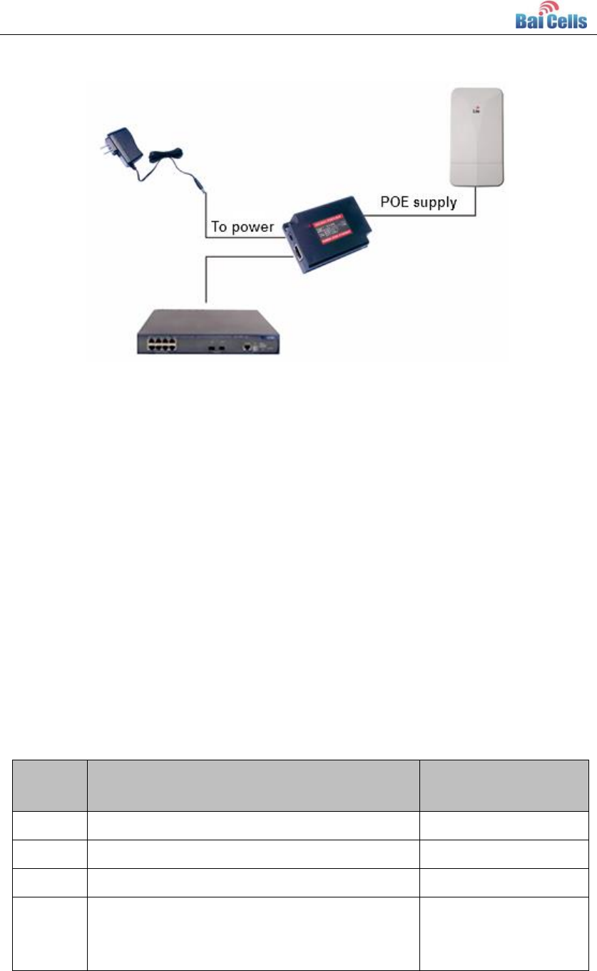
15
Figure 3-13 POE power Mode
Lightning Protection of Cable 3.4
It need to use shielded cable and ensure the grounding of two ends of equipment. If the
opposite equipment has plastic enclosure, which cannot be grounding. In this situation,
the shielded cable function is decreased largely.
If its available, it is recommended that Ethernet cable and power cable pass through metal
sleeve to ground separately. And they cannot be in a same metal sleeve.
It is highly recommended that the distance is as nearest as possible between the two
equipment connected by Ethernet cable, avoiding the cable hanging in the air. According
to the wiring environment, the lightning protection demand is different, the details is
described in Table 3-1.
Table 3-1 Lightning Protection Demand of Cable
Number
Environment
Lightning Protection
Demand
1
Completely in indoor or underground
No special demand
2
Outdoor part exceed 3m
4KV(10/700us)
3
Outdoor part exceed 10m
3KA
4
Outdoor part exceed 10m, and application
environment is poor, such as the cable hanging
in the air, strong lightning area, and so on.
5KA

16
4. Power on Detection
Detection Item 4.1
Power on detection includes the following four items:
Ethernet port working status
CPE configuration check
CPE access test
CPE parameter record
Ethernet Port Working Status 4.2
After CPE powered on, waiting for 2 minutes, connect the Ethernet port of PC to POE
adaptor.
The CW0100 CPE default IP address is 192.168.1.1. Set the IP address of PC is
192.168.1.2, ensure that the Ethernet indicator get light and ping CPE IP address normal.
CPE Configuration Check 4.3
Log in the WebUI of CPE, check whether the software version is correct, whether the LTE
mode is enabled, and whether WAN interface and LAN interface are consistent with plan.
CPE Access Test 4.4
Insert into USIM card, set the WAN interface to LTE mode, set LTE to auto connection,
check terminal connection status, and check whether the terminal can san LTE signal and
get IP address. After the connection is established, service testing can be made, such as
HTTP, FTP, and so on.
CPE Parameter Record 4.5
Record parameter of CPE, such as installation site, installation height, antenna direction
angle, and so on.

17
5. Regulatory Compliance
FCC Compliance
This device complies with part 15 of the FCC Rules. Operation is subject to the
following two conditions: (1) This device may not cause harmful interference, and (2)
this device must accept any interference received, including interference that may
cause undesired operation.
Any Changes or modifications not expressly approved by the party responsible for
compliance could void the user's authority to operate the equipment.
This equipment has been tested and found to comply with the limits for a Class B
digital device, pursuant to part 15 of the FCC Rules. These limits are designed to
provide reasonable protection against harmful interference in a residential installation.
This equipment generates uses and can radiate radio frequency energy and, if not
installed and used in accordance with the instructions, may cause harmful
interference to radio communications. However, there is no guarantee that
interference will not occur in a particular installation. If this equipment does cause
harmful interference to radio or television reception, which can be determined by
turning the equipment off and on, the user is encouraged to try to correct the
interference by one or more of the following measures:
Reorient or relocate the receiving antenna.
Increase the separation between the equipment and receiver.
Connect the equipment into an outlet on a circuit different from that to which the
receiver is connected.
Consult the dealer or an experienced radio/TV technician for help.
Warning
This equipment complies with FCC radiation exposure limits set forth for an
uncontrolled environment. This equipment should be installed and operated with
minimum distance 20 cm between the radiator & your body.

18
IC Compliance
This device complies with Industry Canada licence-exempt RSS standard(s).
Operation is subject to the following two conditions: (1) This device may not cause
interference, and (2) This device must accept any interference, including
interference that may cause undesired operation of the device.
Le présent appareil est conforme aux CNR d'Industrie Canada applicables aux
appareils radio exempts de licence. L'exploitation est autorisée aux deux
conditions suivantes:
(1) l'appareil ne doit pas produire de brouillage, et
(2) l'utilisateur de l'appareil doit accepter tout brouillage radioélectrique subi,
même si le brouillage est susceptible d'en compromettre le fonctionnement.
The antenna(s) used for this transmitter must be installed to provide a
separation distance of at least 20 cm from all persons and must not be
collocated or operating in conjunction with any other antenna or transmitter,
End-Users must be provided with transmitter operation conditions for satisfying
RF exposure compliance.

19
FAQ Appendix A
CPE is unable to power on
Check whether POE power is connected normal.
Check whether the Ethernet cable is damaged
and wire order is correct.
CPE service is unable to running
normal
Check whether it is correct that the network
configuration of CPE.
Check whether the CPE have connected to LTE
network.
CPE receive download signal weak
If external antenna is used, check whether
antenna feed system have connected normal.
(The standing wave measuring can be used.)
Check whether the internal coaxial-cable gets
loose.
CPE is unable to connect base station
Check whether it is normal that the CPE receives
signal.
Check whether the software version that CPE
has download is consistent with the software
version of base station.
Check the data card frequency band of CPE is
consistent with the base station.