Baicells Technologies EG2013B LTE Indoor CPE User Manual ATOM ID06 EG2013B USER Manual
Baicells Technologies Co., Ltd. LTE Indoor CPE ATOM ID06 EG2013B USER Manual
User Manual

01
All rights reserved © Baicells Technologies Co., Ltd.
LTE Indoor CPE - EG2013B USER Manual
About This Document
This document introduces the installation of Baicells LTE Indoor CPE.
Copyright Notice
Baicells copyrights this specification. No part of this specification may be reproduced in
any form or means, without the prior written consent of Baicells.
Disclaimer
This specification is preliminary and is subject to change at any time without notice.
Baicells assumes no responsibility for any errors contained herein. For more information,
please consult our technical engineers.
Revision Record
Date
Version
Description
23 Aug,2017
01
Initial released.
Contact Us
Baicells Technologies Co., Ltd.North America
Address: 555 Republic Drive, Suite 200 Plano, TX 75074
E-mail: support_na@baicells.com
Phone: +1-972-800-1157
Website: http://www.baicells.com
1
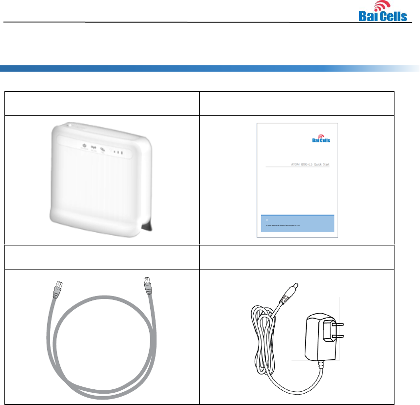
1. Shipping List
Make sure you have got the following parts:
EG2013B
Quick Guide
RJ45 Ethernet cable
AC adaptor
2
2. Hardware Introduction
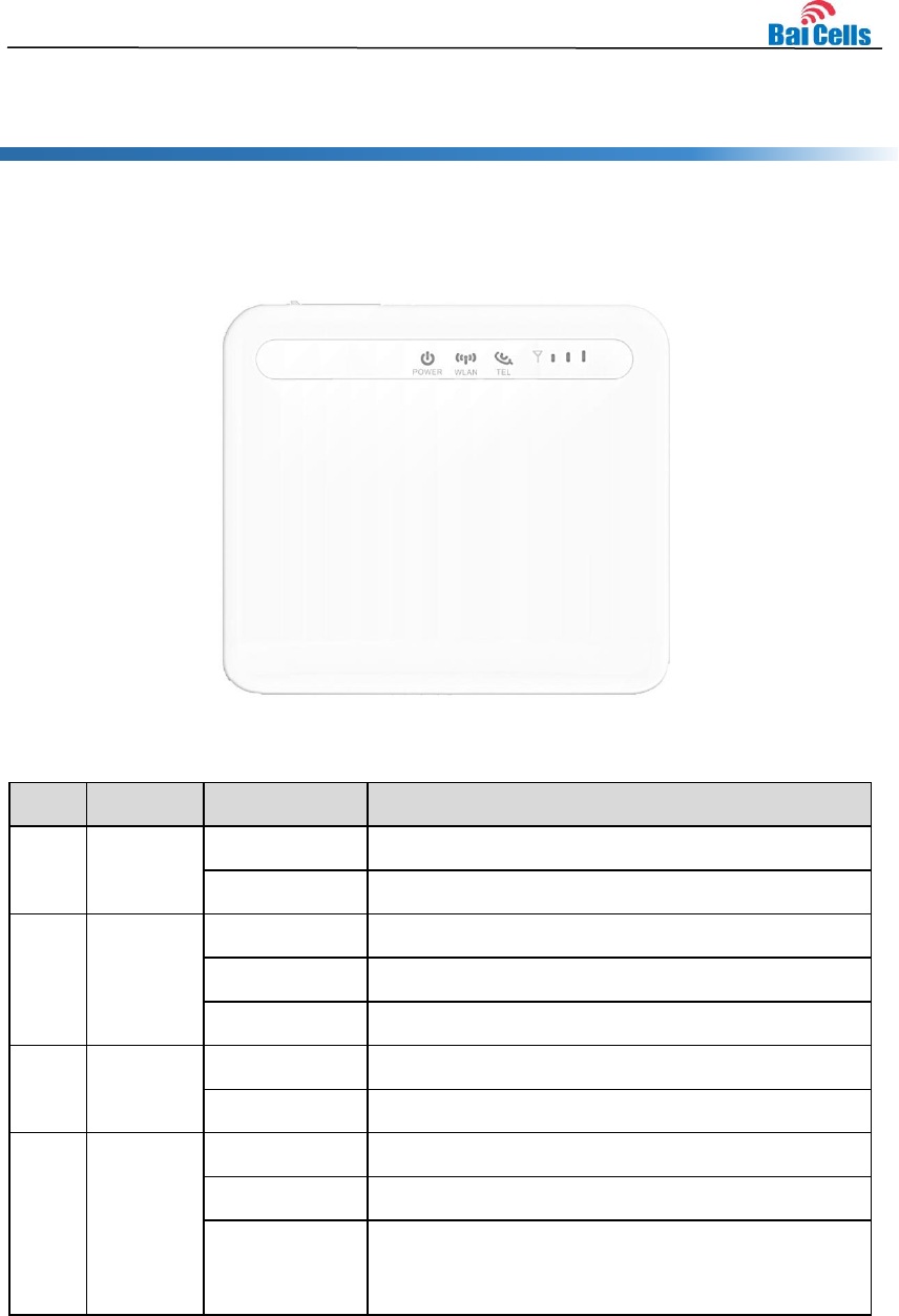
2.1 Indicators
No.
Name
Status
Description
1
Power
Steady On
Power On
OFF
No Power Supply
2
WLAN
Steady On
WiFi enabled
OFF
WiFi disabled
Blanking
Data is transmitting.
3
TEL
Steady On
VoIP having registered
OFF
VoIP having not registered
4
SIGNAL
Steady On
The more turn light up, the stronger signal
OFF
The signal is too weak or no signal
Blanking
The page reload, restore to the factory setting by
page, restore to the factory setting by reset
button or software upgrade
3
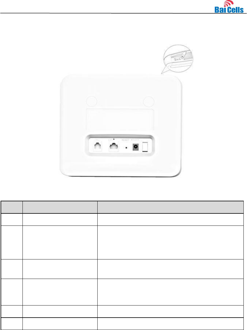
2.2 Interface and Buttons
No.
Name
Description
1
USIM card slot
Insert the USIM card to the slot.
2
Reset Button
Press “Reset” button for 3s~20s, the CPE will
restore to the factory settings. Press “Reset” button
over 20 seconds, the CPE will enable the escape
mechanism.
3
TEL (RJ-11)
TEL interface connects to Telephone by RJ-11
cable.
4
LAN (RJ-45)
LAN interface connects to PC or other network
devices (such hub or switch) by RJ-45 Ethernet
cable.
5
DC-5V (power interface)
Connect to the DC-5V AC adaptor.
6
ON/OFF
ON/OFF the CPE.
4
3. Connect Device
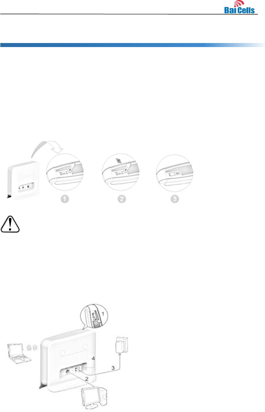
3.1 Insert USIM Card
Install USIM card according to following steps:
1. Open the protective cover of the card slot.
2. Insert USIM card into card slot according to the following figure.
a) Close the protective cover of the card slot.
CAUTION:
DO NOT install or uninstall USIM card when the CPE is running. This operation will
interrupt the performance of the CPE and the data stored in the USIM card may be lost.
3.2 Connect Cable
Install CPE according to following steps:
1. Check whether the USIM card installation is correct.
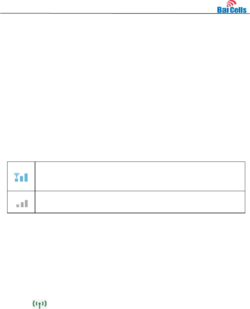
5
2. Connect one end of the RJ-45 cable to LAN interface of the CPE, and the other end
connect to PC.
3. Insert DC-5V AC adaptor to the power interface.
4. Power on.
3.3 Connect Network
Set CPE according to following steps:
1. Open Internet Browser and type in the default IP address: https://192.168.1.1
2. In the user name/password text box, type in the default user name and password,
admin/admin.
On the right corner of the page, there is the icon of signal strength, the two different
status is as follows:
LTE connects to Internet successfully. The signal indictor indicates the
strength of the LTE signal. The more bars turn light up, the stronger
signal, otherwise, the weak signal.
LTE does not connect to the Internet, please check whether the setting is
connect.
3.4 Connect Wi-Fi
Set CPE according to following steps in web page:
1. Before establishing Wi-Fi connection, make sure your wireless terminal devices (such
as notebook, ipad, smart phone) have the WLAN function.
2. When is steady on, the WLAN function of CPE has enabled. If you need to
enable or disable the WLAN function, refer to help information in the web
management page.
3. On the label of back view of the CPE, view the “WLAN Name” and “WLAN Key
(WPA/WPA2)” and record the value.
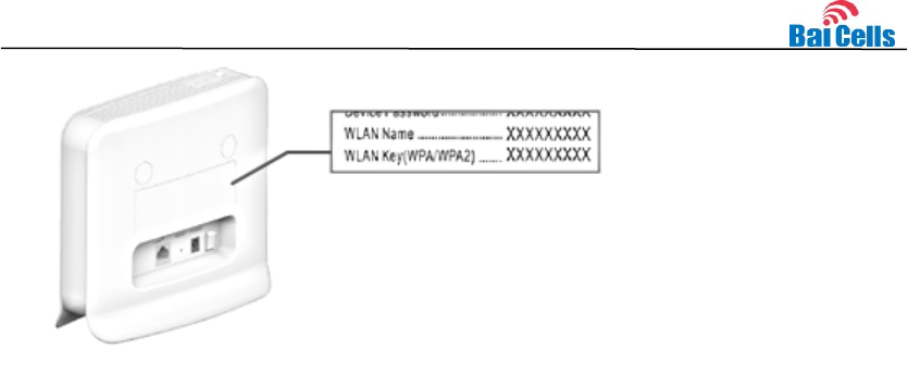
6
To avoid unauthorized user access to the WLAN, please modify the “WLAN Name”
and “WLAN Key (WPA/WPA2)”. For more detail information, refer to help information
in the web management page.
4. Enable WLAN function on wireless terminals, and these devices start to search
nearby available wireless network.
5. Choose the network that the name is the same as “WLAN Name”.
6. Input “WLAN Key (WPA/WPA2)” according to hint. Note the capital and small letter.
When the connection is complete, the page will display whether the connection is
successful.

7
4. Regulatory Compliance
FCC Compliance
This device complies with part 15 of the FCC Rules. Operation is subject to the following
two conditions: (1) This device may not cause harmful interference, and (2) this device
must accept any interference received, including interference that may cause undesired
operation.
Any Changes or modifications not expressly approved by the party responsible for
compliance could void the user's authority to operate the equipment.
This equipment has been tested and found to comply with the limits for a Class B digital
device, pursuant to part 15 of the FCC Rules. These limits are designed to provide
reasonable protection against harmful interference in a residential installation. This
equipment generates uses and can radiate radio frequency energy and, if not installed
and used in accordance with the instructions, may cause harmful interference to radio
communications. However, there is no guarantee that interference will not occur in a
particular installation. If this equipment does cause harmful interference to radio or
television reception, which can be determined by turning the equipment off and on, the
user is encouraged to try to correct the interference by one or more of the following
measures:
Reorient or relocate the receiving antenna.
Increase the separation between the equipment and receiver.
Connect the equipment into an outlet on a circuit different from that to which the
receiver is connected.
Consult the dealer or an experienced radio/TV technician for help.
Warning:
This equipment complies with FCC radiation exposure limits set forth for an uncontrolled
environment. This equipment should be installed and operated with minimum distance 20
cm between the radiator & your body.

8
ISEDC Compliance
This device complies with Innovation, Science, and Economic Development
Canada licence-exempt RSS standard(s).
Operation is subject to the following two conditions: (1) This device may not cause in
terference, and (2) This device must accept any interference, including interference t
hat may cause undesired operation of the device.
Le présent appareil est conforme aux CNR d' Innovation, Science et Développement
économique Canada applicables aux appareils radio exempts de licence.
L'exploitation est autorisée aux deux conditions
suivantes:
(1) l'appareil ne doit pas produire de brouillage, et
(2) l'utilisateur de l'appareil doit accepter tout brouillage radioélectrique subi,
même si le brouillage est susceptible d'en compromettre le fonctionnement.
The antenna(s) used for this transmitter must be installed to provide a separation
distance of at least 20cm from all persons and must not be collocated or operating in
conjunction with any other antenna or transmitter, End-Users must be provided with
transmitter operation conditions for satisfying RF exposure compliance.