Baicells Technologies EG7010A LTE-TDD Base Station User Manual Baicells EG7010A
Baicells Technologies Co., Ltd. LTE-TDD Base Station Baicells EG7010A
UserManual.wiki
>
Baicells Technologies
>
EG7010A User Manual
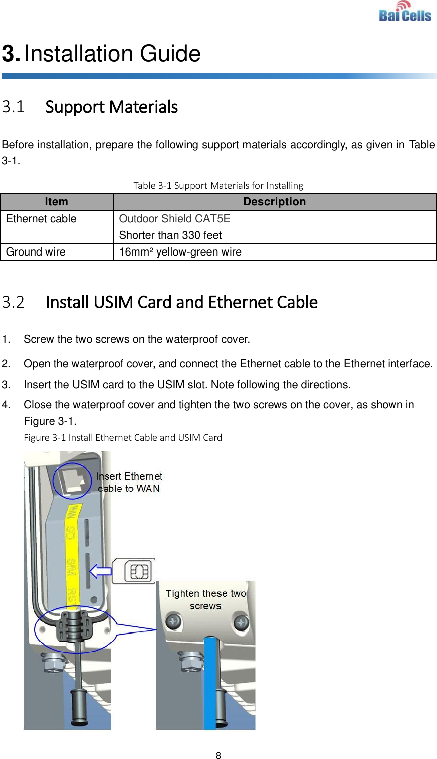
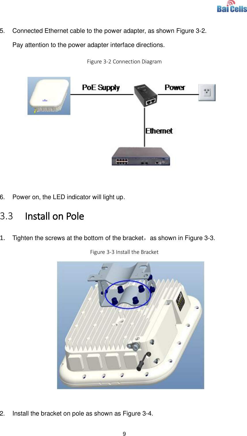
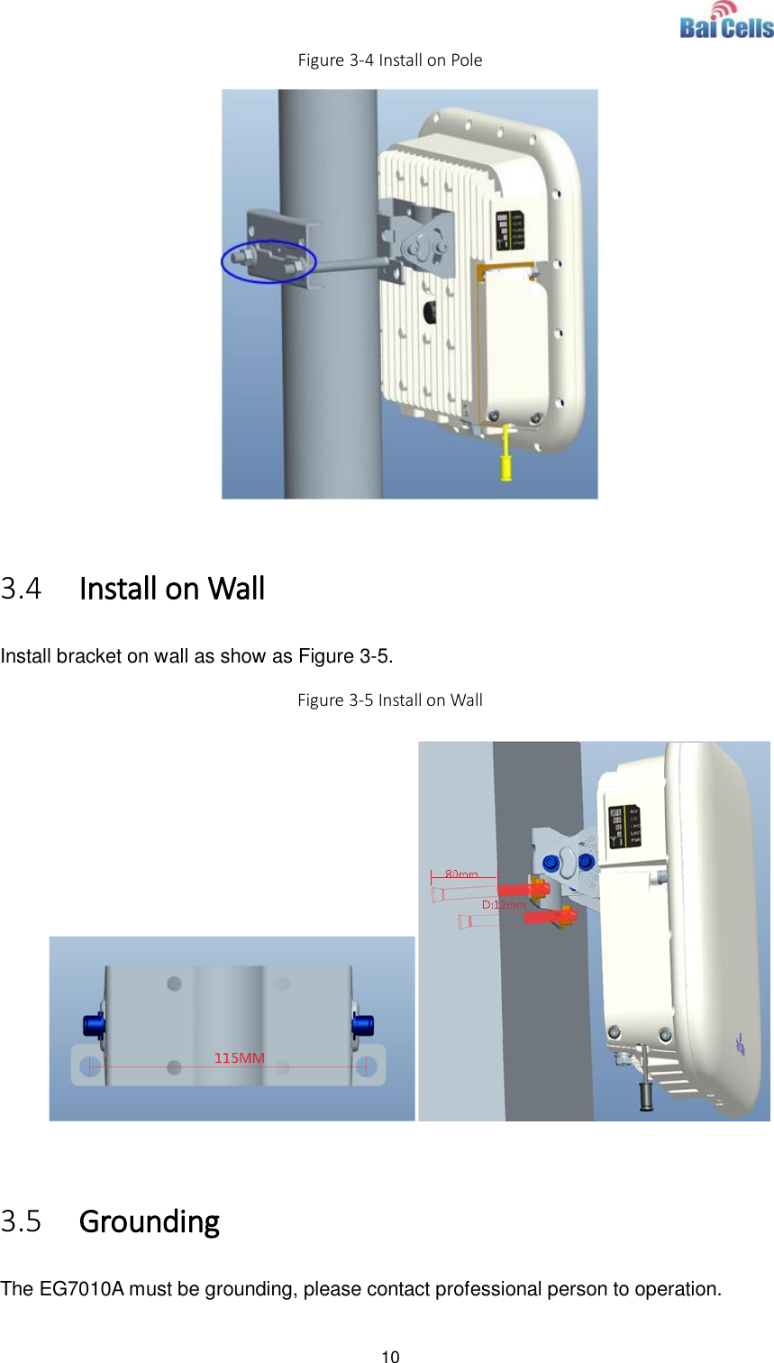
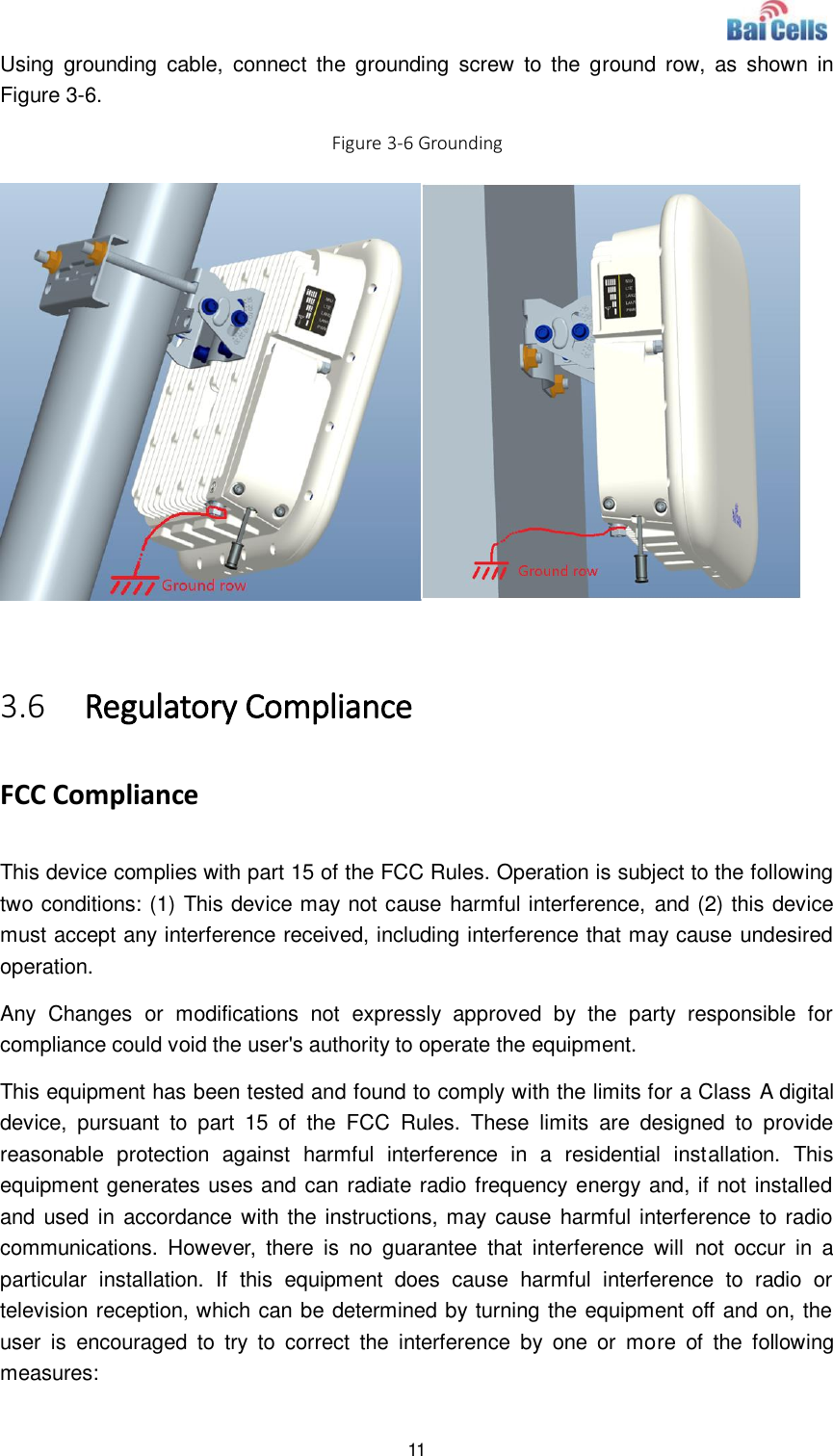
User Manual
Navigation menu
Upload a User Manual
Namespaces
Wiki Guide
HTML
PDF
Info
Views
User Manual
Discussion / Help
Navigation