Baicells Technologies EG7035LM11 LTE Outdoor CPE User Manual Baicells EG7035L M11
Baicells Technologies Co., Ltd. LTE Outdoor CPE Baicells EG7035L M11
User Manual

02
All rights reserved © Baicells Technologies Co., Ltd.
Baicells EG7035L-M11 User Manual
V100R001C00
LTE Outdoor CPE
About This Document
This document introduces the specifications of BaicellsEG7035L-M11 CPE and guides
users to install and configure it.
Copyright Notice
Baicells copyrights this specification. No part of this specification may be reproduced in
any form or means, without the prior written consent of Baicells.
Disclaimer
This specification is preliminary and is subject to change at any time without notice.
Baicellsassumes no responsibility for any errors contained herein. For more information,
please consult our technical engineers.
Disposal of Electronic and Electrical Waste
Pursuant to the WEEE EU Directive, electronic and electrical waste must not
be disposed of with unsorted waste. Pleasecontact your local recycling
authority for disposal of this product.
Revision Record
Date
Version
Description
5June,2017
V1.0
Initial released.
Contact Us
Baicells Technologies Co., Ltd.North America
Address: 555 Republic Drive, Suite 200 Plano, TX 75074
E-mail: support_na@baicells.com
Phone: +1-972-800-1157
Website: http://www.baicells.com/

Contents
1. Product Overview ......................................................................................................... 1
1.1 Introduction .......................................................................................................... 1
1.2 Features ................................................................................................................ 1
1.3 Appearance ........................................................................................................... 1
2. Technical Specifications ............................................................................................... 5
2.1 Basic Specification ................................................................................................ 5
2.2 RF Specification ..................................................................................................... 5
2.3 SW Specification ................................................................................................... 6
2.4 Device Management ............................................................................................... 6
2.5 Environment Specification ...................................................................................... 7
2.6 Regulatory Compliance ........................................................................................... 7
3. Installation Guide.......................................................................................................... 9
3.1 Support Materials ................................................................................................... 9
3.2 Install USIM Card and Cables .................................................................................. 9
3.3 Install on Wall ....................................................................................................... 11
3.4 Install on Pole ....................................................................................................... 12
3.5 Grounding ............................................................................................................ 12
4. Configuration Guide ................................................................................................... 13
4.1 Log in .................................................................................................................... 13
4.2 View Status ........................................................................................................... 13
4.3 Basic Configuration ............................................................................................... 14
4.3.1 LTE Setting .................................................................................................... 14
4.3.2 Set Connection Method................................................................................. 14
4.3.3 Set Scan Mode .............................................................................................. 15
4.3.4 Lock Frequency (Earfcn) ................................................................................ 15
4.3.5 Lock PCI ......................................................................................................... 16
Appendix A FAQs ......................................................................................................... 18


Figures
Figure 1-1 EG7035L-M11 Appearance......................................................................... 2
Figure 1-2 Interface and Button of EG7035L-M11 ....................................................... 2
Figure 1-3 LED Indicators of EG7035L-M11 ................................................................ 3
Figure 4-1 Login Page ................................................................................................ 13
Figure 4-2 View Status ............................................................................................... 14
Figure 4-3 Set Connection Method ............................................................................ 14
Figure 4-4 Set Scan Mode ......................................................................................... 15
Figure 4-5 Lock Frequency ........................................................................................ 16
Figure 4-6 Lock Frequency ........................................................................................ 17

Tables
Table 1-1 Description of EG7035L-M11 Interface and Button ..................................... 2
Table 1-2 LED Indicator Description ............................................................................. 3
Table 2-1 Basic Specification ....................................................................................... 5
Table 2-2 RF Specification ........................................................................................... 5
Table 2-3 SW Specification .......................................................................................... 6
Table 2-4 Device Management ..................................................................................... 6
Table 2-5 Environment Specification ............................................................................ 7
Table 3-1 Support Materials for Installing ..................................................................... 9

1
1. Product Overview
1.1 Introduction
Baicells is a high-tech company dedicated in wireless broadband access solutions and
service operation. With the advent of the Internet+ era, the development of WBB is
imminent. Through continuous innovation, Baicells launches the world first mobile
broadband system based on the Internet architecture and unlicensed spectrum. Baicells
can provide series CPEs, include indoor and outdoor unit on different spectrums.
BaicellsEG7035L-M11 is high performance outdoor CPE. The EG7035L-M11 has the
superior wireless access performance and comprehensive routing capabilities, which
have the abilities to bring the end-users WBB services.
1.2 Features
The EG7035L-M11 is designed according to the simplicity principle, which can evolve in a
short period and realize fast customization, delivery and deployment as well. The main
features of the EG7035L-M11 is as follows:
Support TD-LTE network according to the operator’s choice.
LTE comply with 3GPP Release9 CAT4.
LTE TDD band42&band43.
Support the 100Mbps Ethernet interface.
Intuitionist and convenient Web-based management.
Built-in LTE bipolar directional high gain antenna.
Support TR069 and OMA-DM network management protocol.
Support cell lock, SIM lock, and Pin lock.
User-friendly design of LED indicator.
Power supply with PoE.
Support pole installation or wall mounting.
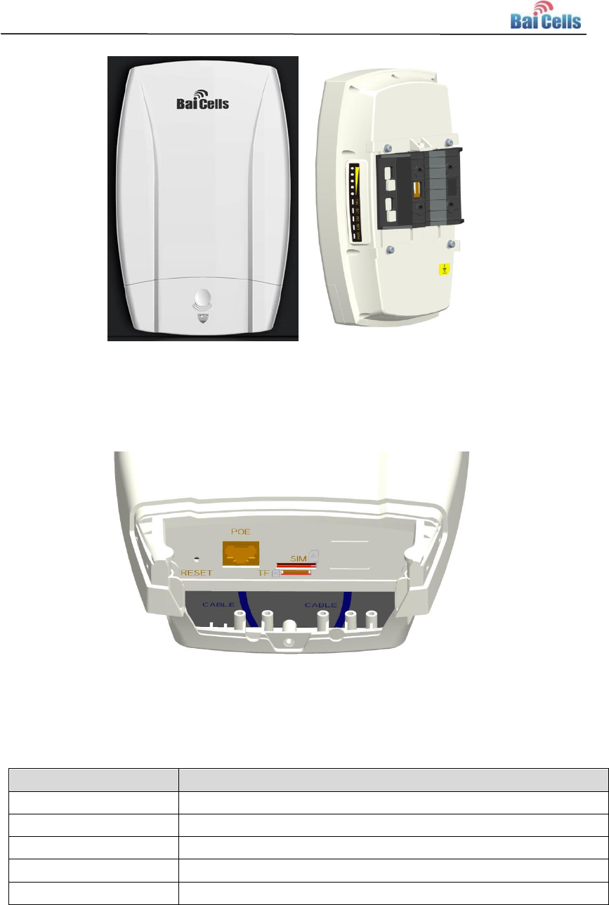
1.3 Appearance
The EG7035L-M11 appearance is shown in Figure 1-1.
2
Figure 1-1EG7035L-M11 Appearance
The EG7035L-M11 interfaces and buttons are shown in Figure 1-2.
Figure 1-2Interface and Button of EG7035L-M11
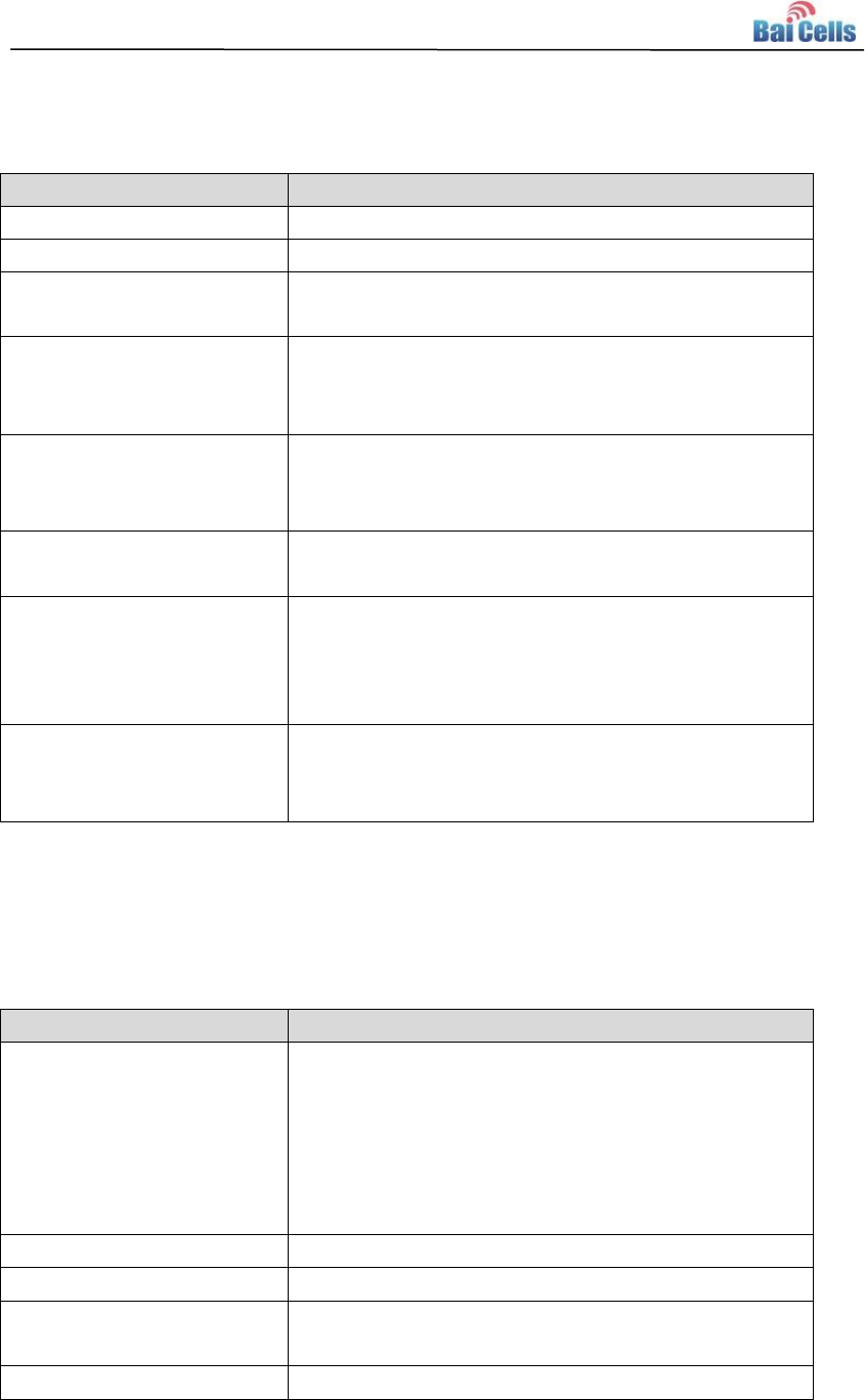
The EG7035L-M11 interface and button description is given in Table 1-1.
Table 1-1 Description of EG7035L-M11 Interface and Button
Interface & Button
Description
PoE
Connected to the PoEpower adapter
TF
Support SD card
SIM
Support 1.8V/3.0V USIM 2FF
RESET
Long press over 10 seconds to restore the factory settings
GND
Connected to Earth by conductor
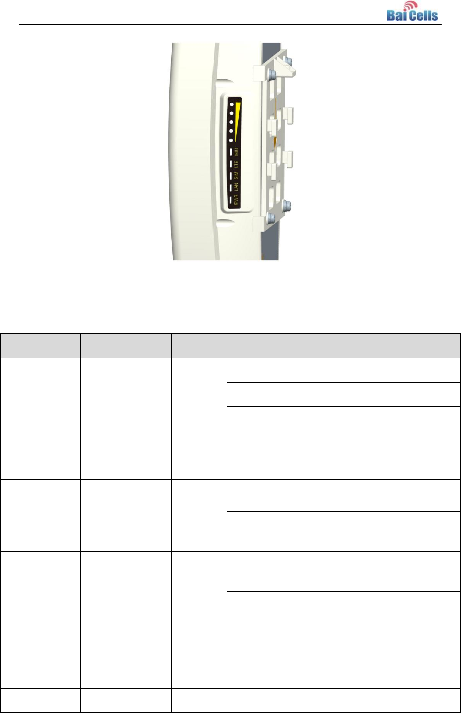
The LED indicators are shown in Figure 1-3.
3
Figure 1-3 LED Indicators of EG7035L-M11
The description of LED indicators are given in Table 1-2.
Table 1-2 LED Indicator Description
Identity
Description
Color
Status
Description
MIU
-
Yellow
OFF
Reserved.
Steady On
Reserved.
Blanking
Reserved.
LTE
Network state
Indicator
Blue
OFF
LTE disconnected.
Steady On
LTE connected.
SIM
SIM card status
indicator
Yellow
Steady On
The SIM card is normal.
Blanking
The SIM card is abnormal or not
inserted.
LAN
100Mbps Eth
Indication
Yellow
OFF
Ethernet connection does not
established.
Steady On
Ethernet connection is normal.
Blanking
Data is transmitting.
PWR
Power Indicator
Yellow
OFF
No Power Supply
Steady On
Power On
LTE Signal
5 LTEs, Indicate
Green
All OFF
Signal is too weak to attach.

4
Identity
Description
Color
Status
Description
connection state
and signal
strength
Steady On
According to signal strength in
turn light up
Blanking
Scanning the LTE network
The CPE is authenticating.
CPE is getting IP address from
the LTE network.
5
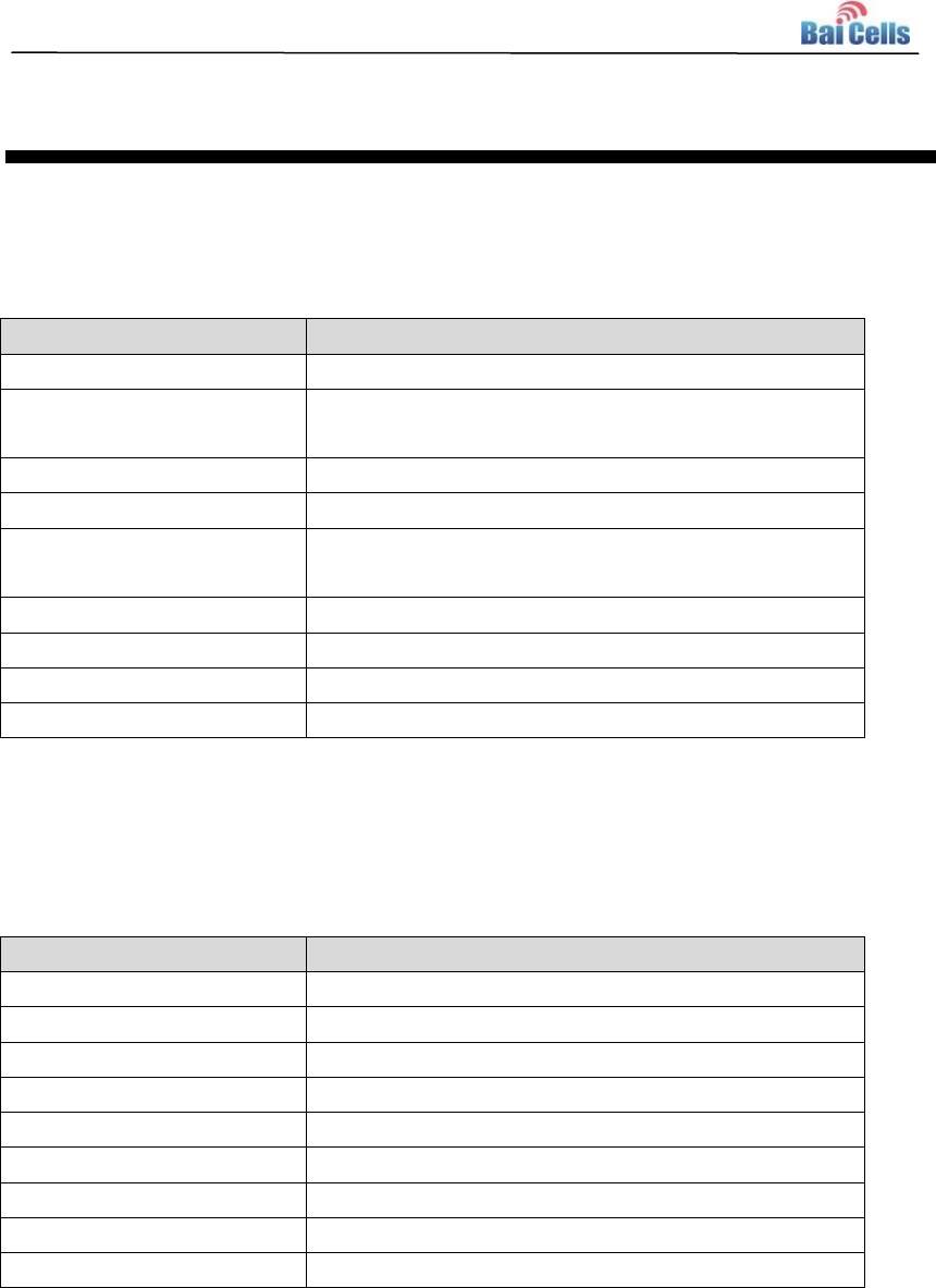
2. Technical Specifications
2.1 Basic Specification
Table 2-1 Basic Specification
Item
Description
LTE Standard
3GPP Release 9
Ethernet LAN Port
One RJ-45 port 10/100 auto-sensing, auto-MDX,
PoE
LED Indicators
Power/LET Signal/LAN Indicator
USIM
Support 1.8V/3V 2FF
Restore Button
Tact Button
Long press over 10s to restore the factory settings
Power Supply
Input: Universal range 100V~240V AC
Dimension
About 241mm * 154mm * 50mm
Weight
About 900g
Color
Pantone white C
2.2 RF Specification
Table 2-2 RF Specification
Item
Description
LTE Mode
TDD LTE
Channel Bandwidth
5 MHz /10 MHz /15 MHz /20 MHz
MAX Output Power
23±2dBm
LTE Standard
3GPP R9
Frequency
Band43: 3650 MHz ~ 3700 MHz
LTE Antenna Gain
10dBi
Wifi Standard
802.11b/g/n
Frequency
2400MHz~2483.5MHz
Wifi Antenna Gain
0dBi
6
2.3 SW Specification
Table 2-3SW Specification
Item
Description
Language Settings
English
Network Mode
Bridge / NAT
SIM
PIN Management
SIM Lock
Network Connection setup
Create, delete, and edit APNs
Set up dial-up connection automatically
Set up dial-up connection manual
LTE Scan Mode
Full Band
Cell Lock
Band / Frequency Preferred
VPN
Support VPN pass through
Support PPTP tunnel mode
NAT
Port forwarding
Port trigger
DMZ
UPnP
Statistics
LAN Link Status
Transmit / Receive traffic
Running Time
2.4 Device Management
Table 2-4Device Management
Item
Description
Maintenance
Date & Time setting
Reset
Restore factory settings
Restore/Backup Configuration File
Local upgrade
FOTA upgrade
TR069
Can enable or disable TR069 Management
Port mirror
Can enable or disable the port mirror function
Syslog
Support the syslog function can send the log to the
PC via LAN
Diagnostics
Support the Ping and trace route
7
2.5 Environment Specification
Table 2-5Environment Specification
Item
Description
Operating Temperature
-40℃ ~ 55℃
Storage Temperature
-40℃ ~ 70℃
Operating Humidity
5% ~ 95%
2.6 Regulatory Compliance
FCC Compliance
This device complies with part 15 of the FCC Rules. Operation is subject to the
following two conditions: (1) This device may not cause harmful interference, and (2)
this device must accept any interference received, including interference that may
cause undesired operation.
Any Changes or modifications not expressly approved by the party responsible for
compliance could void the user's authority to operate the equipment.
This equipment has been tested and found to comply with the limits for a Class A
digital device, pursuant to part 15 of the FCC Rules. These limits are designed to
provide reasonable protection against harmful interference when the equipment is
operated in a commercial environment. This equipment generates, uses, and can
radiate radio frequency energy and, if not installed and used in accordance with the
instruction manual, may cause harmful interference to radio communications.
Operation of this equipment in a residential area is likely to cause harmful
interference in which case the user will be required to correct the interference at his
own expense.
Warning
This equipment complies with FCC radiation exposure limits set forth for an
uncontrolled environment. This equipment should be installed and operated with
minimum distance 30cm between the radiator & your body.
ISEDCCompliance
This device complies with Innovation, Science, and Economic Development
Canada licence-exempt RSS standard(s).

8
Operation is subject to the following two conditions: (1) This device may not cause in
terference, and (2) This device must accept any interference, including interference t
hat may cause undesired operation of the device.
Le présent appareil est conforme aux CNR d'Innovation, Science et Développement
économique Canada applicables aux appareils radio exempts de licence.
L'exploitation est autorisée aux deux conditions
suivantes:
(1) l'appareil ne doit pas produire de brouillage, et
(2) l'utilisateur de l'appareil doit accepter tout brouillage radioélectrique subi,
même si le brouillage est susceptible d'en compromettre le fonctionnement.
The antenna(s) used for this transmitter must be installed to provide a separation
distance of at least 30cm from all persons and must not be collocated or operating in
conjunction with any other antenna or transmitter, End-Users must be provided with
transmitter operation conditions for satisfying RF exposure compliance.
9
3. Installation Guide
3.1 Support Materials
Before installation, prepare the following support materialsaccordingly, asgiven in Table
3-1.
Table 3-1Support Materials for Installing
Item
Description
Ethernet cable
Outdoor Shield CAT5E
Shorter than 330 feet
Ground wire
16mm² yellow-green wire
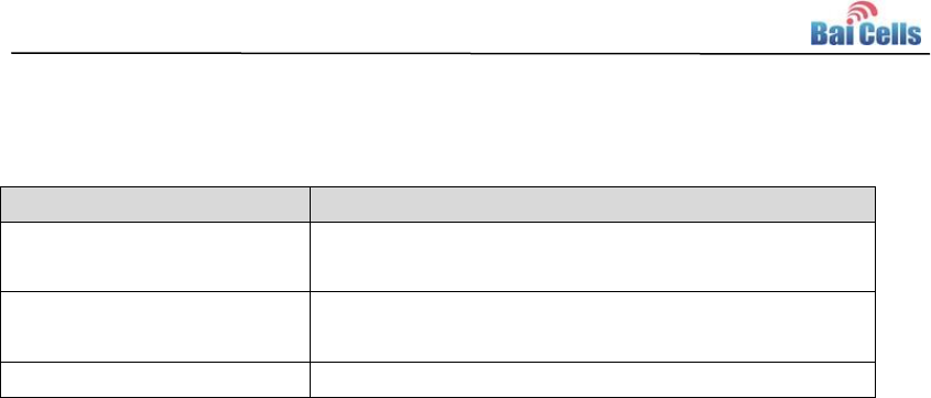
3.2 Install USIM Card and Cables
1. Screw the screw on the waterproof cover, and open the waterproof cover.
2. Insert the USIM card to the USIM slot. Note following the directions.
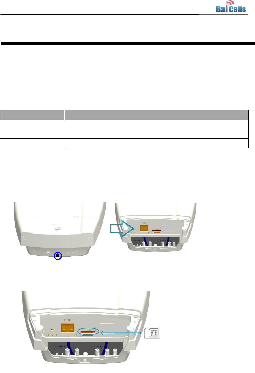
3. Connect the Ethernet cable to the POE port, and connect the ground cable to the
ground screw.
10
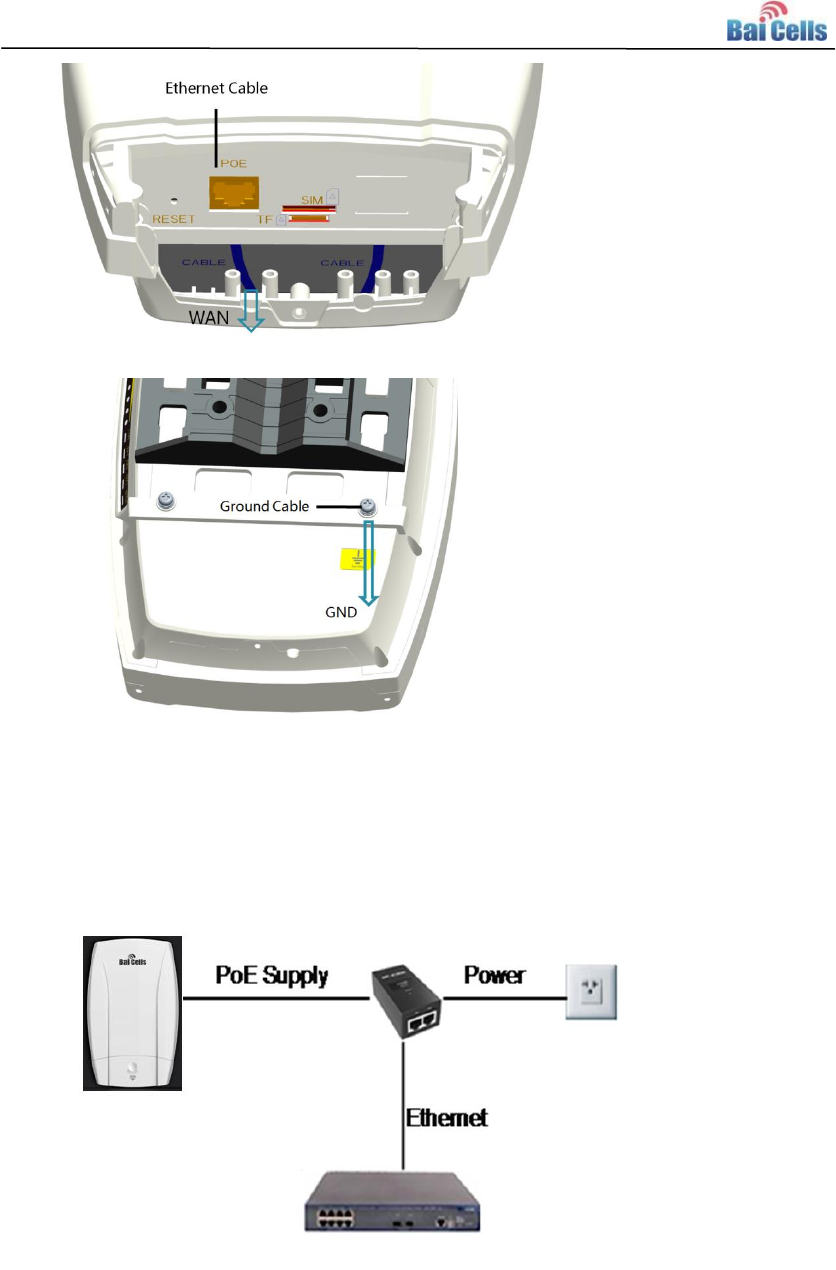
4. Close the waterproof cover and fasten the screw on the cover.
5. Connected Ethernet cable to the power adapter.
Pay attention to the power adapter interface directions.
6. Power on, the LED indicator will light up.
11
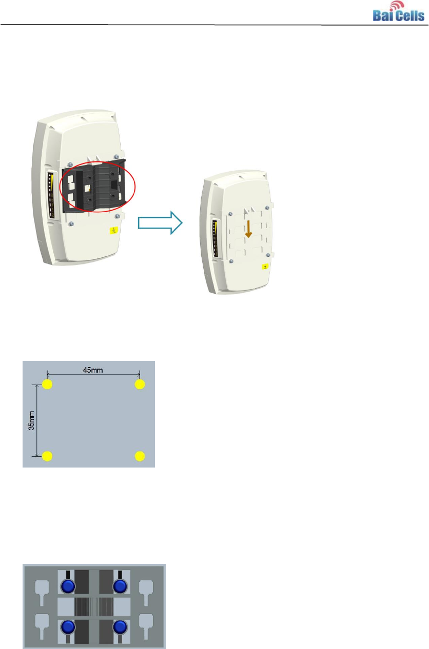
3.3 Install on Wall
1. Slipping the bracket from the CPE.
2. Fit the CPE on the wall, and mark the drilling locations.
3. Drill four 10mm diameter and 70mm depth holes in the wall by following the
marked locations.
4. Check the up/down direction of the bracket, and then fix it on wall using
M5tapping screws.
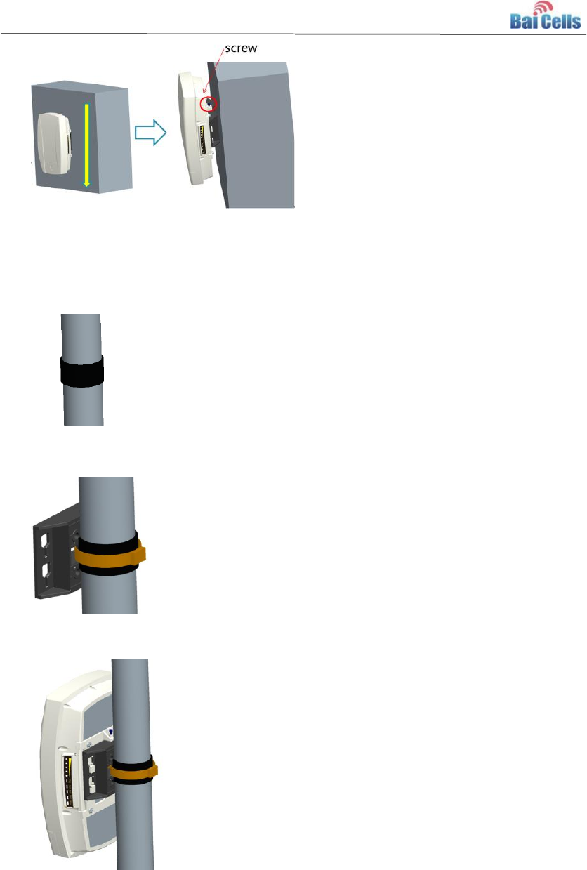
5. Install the CPE to the bracket and fasten the screw.
12
3.4 Install onPole
1. Round an anti-slip rubber on the pole.
2. Fix the bracket using the hoop.
3. Install the CPE to the bracket and fasten the screw.
3.5 Grounding
The EG7035L-M11 must begrounding, please contact professional person to operation.
Using grounding cable, connect the grounding cable to the ground row.
13
4. Configuration Guide
4.1 Log in
The EG7035L-M11 manages, configures, and maintains the device by web management
page.The steps to log in are as follows:
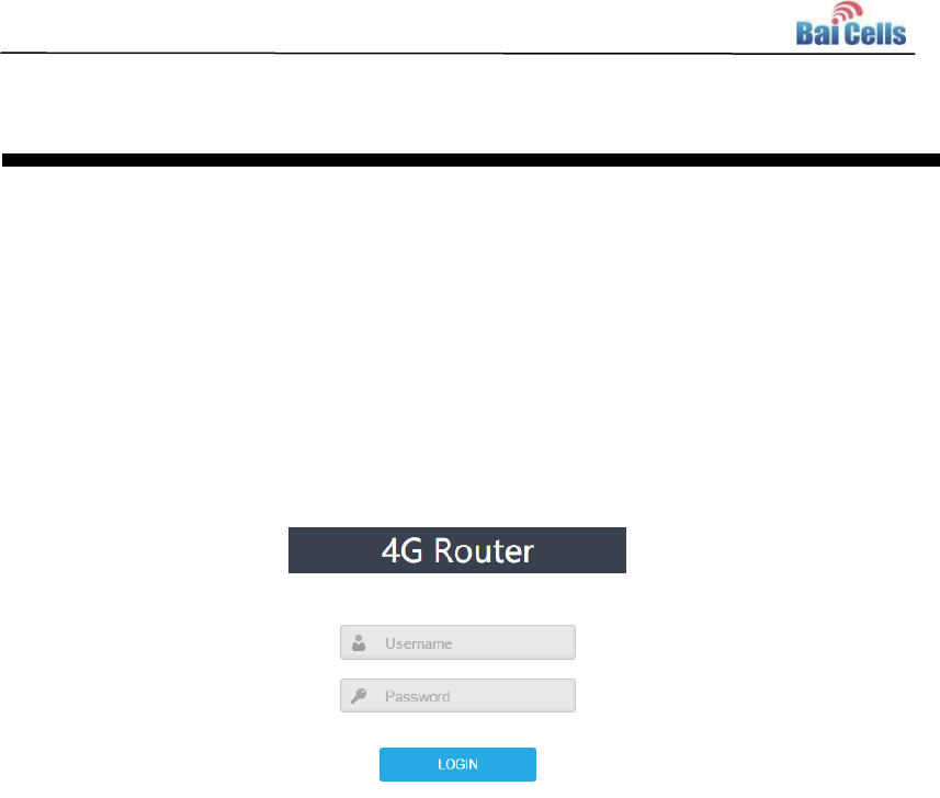
1. In the address column of browser, type in http://192.168.150.1, then press “Enter”,
login in page is shown in Figure 4-1.
Figure 4-1 Login Page
2. Enter the user name and password, click "LOGIN". After password authentication,
you can log on to the web management page.
The default user name and password is admin.
For security, it is recommended that you open the firewall, and keep your login password,
WLAN FTP passwords and password well.
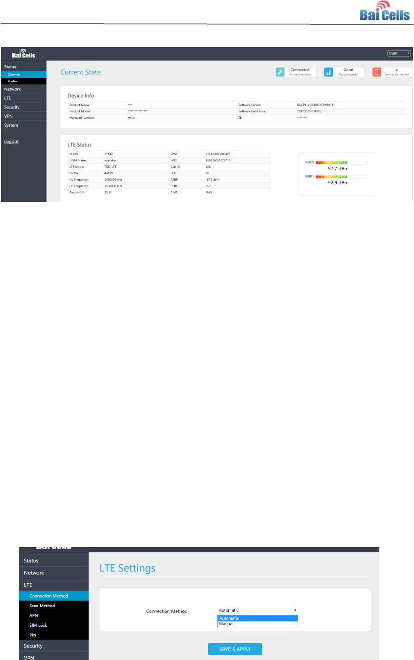
4.2 View Status
In the overview area, you can view the device information and LTE status,such as Product
name, Software version, PLMN, IMSI, RSRP, RSRQ, CINR, SINR, Tx Power, Cell ID, PCI,
and so on, as shown in Figure 4-2.
14
Figure 4-2 View Status
4.3 Basic Configuration
4.3.1 LTE Setting
To set the LTE Network, perform the following steps:
1. Choose LTE.
2. In the LTE Setting area, configure the LTE network.
4.3.2 Set Connection Method
To set the LTE network connection method, perform the following steps:
1. Choose “LTE>connection Method”, enter the setting connection method page, as
shown in Figure 4-3.
Figure 4-3 Set Connection Method
15
2. In the connection Method area, set the connection method
3. There are two methods to connect the LTE network, it is needed to choose a method
between Auto and Manual, if you want to auto connect to the LET network you should
choose the Auto, otherwise you should choose Manual.
4. Click “SAVE & APPLY”.
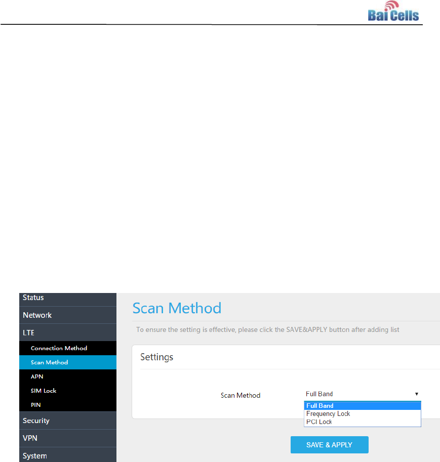
4.3.3 Set Scan Mode
To set the LTE network scan mode, perform the following steps:
1. Choose “LTE>Scan Method”, enter the setting scan method page, as shown in Figure
4-4.
Figure 4-4 Set Scan Mode
2. In the Scan Method area, set the scan mode
3. You can choose full Band, Frequency Lock, or PCI Lock.
4.3.4 Lock Frequency (Earfcn)
To clock the frequency, perform the following steps:
1. Choose “LTE>Scan Method”.
2. In the LTE Scan Method area, click Frequency Lock to lock the frequency.
3. Click ADD LIST, choose a band and frequency, and then click Add to add the band
and frequency to the list, as shown in Figure 4-5.
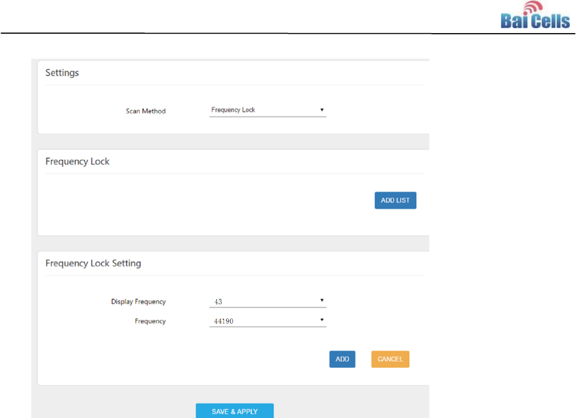
16
Figure 4-5 Lock Frequency
4. Click “SAVE & APPLY”.
4.3.5 LockPCI
To lock the PCI, perform the following steps:
1. Choose “LTE>Scan Method”.
2. In the LTE Scan Method area, click PCI Lock to lock the PCI.
3. Click ADD LIST you can choose a band, frequency and PCI, then click Add to add the
frequency and PCI to the list, as shown in Figure 4-6.
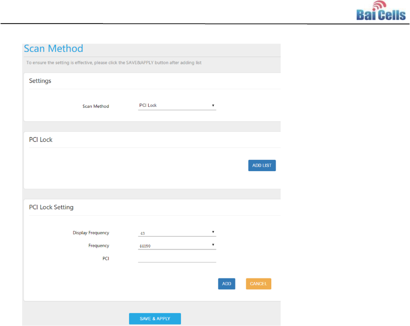
17
Figure 4-6 Lock Frequency
4. Click “SAVE & APPLY”.

18
Appendix A FAQs
The POWER indicator does not turn on.
Make sure that the power cable is connected properly and the CPE is powered on.
Make sure that the power adapter is compatible with the CPE.
Fails to Login to the web management page.
Make sure that the CPE is started.
Verify that the CPE is correctly connected to the computer through a network cable. If
the problem persists, contact authorized local service suppliers.
The CPE fails to search for the wireless network.
Check that the power adapter is connected properly.
Check that the CPE is placed in an open area that is far away from obstructions, such
as concrete or wooden walls.
Check that the CPE is placed far away from household electrical appliances that
generate strong electromagnetic field, such as microwave ovens, refrigerators, and
satellite dishes.
If the problem persists, contact authorized local service suppliers.
The power adapter of the CPE is overheated.
The CPE will be overheated after being used for a long time. Therefore, power off the
CPE when you are not using it.
Check that the CPE is properly ventilated and shielded from direct sunlight.
The parameters are restored to default values.
If the CPE powers off unexpectedly while being configured, the parameters may be
restored to the default settings.
After configuring the parameters, download the configuration file to quickly restore the
CPE to the desired settings.
19
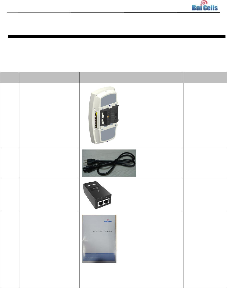
Appendix B Shipping List
The product outward appearance, the color take the material object as, the picture only
supply reference.
Index
Content
Picture
Amount
1
EG7035L-M11 CPE
with Simple
Mounting bracket
1
2
Power cord
1
3
PoEadapter
1
4
User Manual
1