Baicells Technologies MBS1105 LTE-TDD Base Station User Manual Baicells mBS1105 Base Station Installation Guide
Baicells Technologies Co., Ltd. LTE-TDD Base Station Baicells mBS1105 Base Station Installation Guide
Users Manual

01
All rights reserved © Baicells Technologies Co., Ltd.
Baicells mBS1105 Base Station Installation Guide
V100R001C00
Baicells mBS1105 Base Station Installation Guide(V100R001C00,02).docx
About This Document
This document is a guidance of mBS1105 hardware installation for installation
personnel, which includes the preparation of installation tools and supporting
materials before installation, the demands of installation environment, installation of
base station, connection of cable and power on.
Accomplish the installation of the device according to this guide, the installation
personnel can avoid potential damage to the device during the installation
procedure, which makes sure the subsequent good running of the device.
Copyright Notice
Baicells copyrights this specification. No part of this specification may be reproduced in
any form or means, without the prior written consent of Baicells.
Disclaimer
This specification is preliminary and is subject to change at any time without notice.
Baicells assumes no responsibility for any errors contained herein. For more information,
please consult our technical engineers.
Disposal of Electronic and Electrical Waste
Pursuant to the WEEE EU Directive, electronic and electrical waste must not
be disposed of with unsorted waste. Please contact your local recycling
authority for disposal of this product.
Revision Record
Date
Version
Description
24 Mar, 2017
V1.0
Initial Released.
Contact Us
Baicells Technologies Co., Ltd.North America
Address: 555 Republic Drive, Suite 200 Plano, TX 75074
E-mail: support_na@baicells.com
Phone: +1-972-800-1157
Website: http://www.baicells.com/

Baicells mBS1105 Base Station Installation Guide(V100R001C00,02).docx
Contents
1. Product Overview ....................................................................................................... 1
Introduction ............................................................................................................... 1 1.1
Features ...................................................................................................................... 1 1.2
Appearance ................................................................................................................ 2 1.3
Technical Specification ............................................................................................... 3 1.4
1.4.1 Hardware Specification....................................................................................... 3
1.4.2 Software Specification ........................................................................................ 4
1.4.3 Environment Specification .................................................................................. 5
2. Out-of-Box Audit ......................................................................................................... 6
3. Installation Preparation .............................................................................................. 7
Support Materials ..................................................................................................... 7 3.1
Installation Tools ...................................................................................................... 7 3.2
Installation Environment ............................................................................................ 8 3.3
3.3.1 Locational Requirements .................................................................................... 8
3.3.2 Environmental Requirements ............................................................................. 8
3.3.3 Space Requirements ........................................................................................... 8
Personnel Requirements ............................................................................................ 9 3.4
Lightening and Grounding Protection ........................................................................ 9 3.5
Weatherproof Protection ......................................................................................... 10 3.6
4. Base Station Installation ............................................................................................. 11
Installation Procedure ............................................................................................ 11 4.1
Install the Mounting Bracket and Handle ................................................................ 11
4.2
Install GPS Antenna .................................................................................................. 12 4.3
Install on Pole ........................................................................................................... 13 4.4
Install on Wall ........................................................................................................... 15 4.5
Connect Cable .......................................................................................................... 16 4.6
4.6.1 Requirement for Cable Laying .......................................................................... 16

Baicells mBS1105 Base Station Installation Guide(V100R001C00,02).docx
4.6.2 Connect GPS Antenna ....................................................................................... 16
4.6.3 Connect RF Cable .............................................................................................. 17
4.6.4 Connect Optical Fiber ....................................................................................... 17
4.6.5 Connect Ethernet Cable .................................................................................... 17
4.6.6 Connect Power Connector ................................................................................ 17
4.6.7 Connect Ground Cable ...................................................................................... 18
Install Antenna Feeder System................................................................................. 18 4.7
4.7.1 Install Omnidirectional Antennas ..................................................................... 18
4.7.2 Install Directional Antennas.............................................................................. 20
5. Power On ........................................................................................................................ 22
Appendix A Additional Information.................................................................................. 23
A.1 Antenna Information ................................................................................................ 23
A.2 Maximum Output Power.......................................................................................... 24
A.3 Regulatory Compliance ............................................................................................ 24

Baicells mBS1105 Base Station Installation Guide(V100R001C00,02).docx
Figures
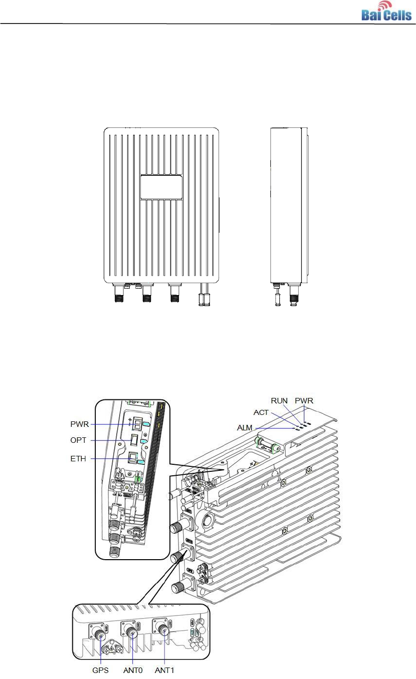
Figure 1-1 mBS1105 Appearance ................................................................................ 2
Figure 1-2 mBS1105 Interfaces and Indicators ............................................................ 2
Figure 3-1 Installation Space Requirement .................................................................. 9
Figure 3-2 Antenna Weatherproofing ......................................................................... 10
Figure 4-1 Installation Procedure of mBS1105 .......................................................... 11
Figure 4-2 Install the Mounting Bracket ..................................................................... 12
Figure 4-3 Location of Grounding Screws .................................................................. 18
Figure 4-4 Omnidirectional Antenna Installation (1) ................................................... 19
Figure 4-5 Omnidirectional Antenna Installation (2) ................................................... 20
Figure 4-6 Assembling Procedure of Directional Antennas ....................................... 20
Figure 4-7 Transportation the Antennas in the Height ............................................... 21
Figure 4-8 Directional Antenna Installation ................................................................ 21
Figure 5-1 LED Indicators .......................................................................................... 22

Baicells mBS1105 Base Station Installation Guide(V100R001C00,02).docx
Tables
Table 1-1 mBS1105 Interface Description .................................................................... 3
Table 1-2 mBS1105 Interface Indicators ...................................................................... 3
Table 2-1 Shipping List ................................................................................................. 6
Table 3-1 Support Materials for Installing Base Station ............................................... 7
Table 3-2 Environmental Requirements of the Base Station ....................................... 8
Table 5-1 mBS1105 Indicator Description .................................................................. 22
Table 5-2 Antenna Information ................................................................................... 23

Baicells mBS1105 Base Station Installation Guide(V100R001C00,02).docx
1
1. Product Overview
Introduction 1.1
Baicells mBS1105 is a high performance outdoor 3.65GHz micro base station based on
TD-LTE technology, which is developed by Baicells. The mBS1105 supports wired
backhaul connections to backbone networks, and provides LTE access to user terminals,
implemented voice and data service transmissions.
The mBS1105 makes use of the current transmission resources to reduce the
operator’s investment, implement the low-cost construction of LTE networks and
enhance indoor coverage, thereby providing high-speed broadband access for
users in assembly occupations.
The mBS1105 can be widely used by telecom operators, broadband operators,
enterprises, and so on.
Features 1.2
Adopt the integration design of baseband and RF.
Based on 3GPP international standard TD-LTE technology; provide high speed data
service; support a maximum transfer rate of DL: 110Mbit/s, UL: 20Mbit/s.
Support flexible uplink and downlink time slot ratio: 1(2:2), 2(1:3), and high speed
data transmission.
Support 10MHz/20MHz operation bandwidth.
Support copper (RJ-45) and optical port backhaul, flexible to deploy.
Security services to provide timely protection against potential security risks and
illegal intrusion.
Support simple and convenient local and remote web management.
Integration as required, easy to installation and deployment, accurate
coverage and improved network capacity.
Support network management functions, which includes the management,
monitoring and maintenance.

Baicells mBS1105 Base Station Installation Guide(V100R001C00,02).docx
3
The mBS1105 interfaces are described in Table 1-1.
Table 1-1 mBS1105 Interface Description
Interface Name
Description
PWR
Power interface: +48V (+42V~+60V) DC
GPS
External GPS antenna, N-female connector.
ANT0
External antenna 0, N-female connector.
OPT
Optical interface, connect to external transmission network,
used for data backhaul.
ETH
RJ-45 interface, used for debug or data backhaul.
ANT1
External antenna 1, N-female connector.
The mBS1105 interface indicators are described in Table 1-2.
Table 1-2 mBS1105 Interface Indicators
Identity
Color
Status
Description
PWR
Green
Steady On
Power On
OFF
No Power Supply
RUN
Green
Fast flash: 0.125s
on,0.125s off
The board is loading.
Slow flash: 1s on,1s
off
The board is normal.
OFF
No power input or board fault
ACT
Green
Steady On
The transmitting channel works
normally
OFF
The transmitting channel works
abnormally
ALM
Red
Steady On
Hardware alarm, e.g. VSWR alarm
OFF
No alarm
Technical Specification 1.4
1.4.1 Hardware Specification
Item
Description
LTE Mode
LTE TDD
LTE Frequency
3650 MHz ~ 3700 MHz
Channel Bandwidth
10 MHz, 20 MHz
Max Output Power
33 dBm

Baicells mBS1105 Base Station Installation Guide(V100R001C00,02).docx
4
Item
Description
Receiving sensitivity
-102 dBm
Synchronization
Mode
Air-interface same frequency synchronization
GPS synchronization
Backhaul Mode
Optical and RJ-45 Ethernet backhaul
MIMO
2*2MIMO
Dimension
227mm (L) * 305mm (W) * 74mm (H)
Installation Method
Pole mounted, wall mounted
Antenna
External high gain antenna
Overall Power
< 50 W
Power
48V DC
Weight
About 4.4kg
Note:
The test method of receiving sensitivity is proposed by the 3GPP TS 36.104, which is based on 5MHz
bandwidth, FRC A1-3 in Annex A.1 (QPSK,R=1/3,25RB) standard.
1.4.2 Software Specification
Item
Description
LTE Standard
LTE TDD 3GPP Release 9
Maximum
Throughput
20MHz: DL 110Mbps, UL 20Mbps
10MHz: DL 55Mbps, UL 9Mbps
Business
Capacity
32 concurrent users (support software upgrading the users to
96)
Modulation Mode
QPSK, 16QAM, 64QAM
Voice Solution
Support CSFB, VoLTE, SRVCC
Traffic Offload
(optional)
Support LIPA/SIPTO, which is Local IP Access and Selected
IP Traffic Offload for short
SON
Self-organizing network: support plug and play, automatic start,
optimization and configuration
RAN Sharing
Support
Network
Management
Interface
Support TR069 interface protocol
Northbound
Interface
Support Web service, Socket, FTP and other interface modes
MTBF
≥ 150000 hours
MTTR
≤ 1 hour
Maintenance
Support remote/local maintenance, based on SSH protocol
Support remote maintenance

Baicells mBS1105 Base Station Installation Guide(V100R001C00,02).docx
5
Item
Description
Support online status management
Support performance statistics
Support failure management
Support configuration management
Support local or remote software upgrading and loading
Support log
Support connectivity diagnosis
Support automatic start and configuration
Support alarm reporting
1.4.3 Environment Specification
Item
Description
Operating Temperature
-40°C ~ 55°C
Humidity
5% ~ 100%
Change Rate of
Temperature
1℃/min
Atmospheric Pressure
70kPa ~ 106kPa
IP Protection Grade
IP66
Lightning Protection
Power interface: differential mode: ±10KA common
mode: ±20KA

Baicells mBS1105 Base Station Installation Guide(V100R001C00,02).docx
6
2. Out-of-Box Audit
Before opening the box, make sure the package is in good condition, undamaged and
not wet. During the unpacking, avoid potential damaging impacts from hits or excessive
force. Once unpacked, check the contents to see if they are consistent with that in the
shipping list shown in Table 2-1.
Table 2-1 Shipping List
Number
Item
Quantity
Description
1
mBS1105 base
station
1
Check whether the base station’s tag
is consistent with the requirement
2
Power supply
1
100V ~ 277V AC to 48V DC
3
Power terminal
1
2 wires green terminal
4
GPS antenna and RF
cable
1
-
5
Installation bracket
and its screws
-
Omega 4
Installation bracket 1
M10*160 outer hex bolt 4
M10 flat gasket 10
M10 spring cushion 10
M10 screw 10
M8*80 expansion bolt 2
6
eNodeB bracket and
its screws
-
eNodeB fixing bracket 1
M6*16 hex combination screw 4
7
GPS mounting
bracket and its
screws
1
Fixed accessories of GPS
M4*14 screw 2
8
Ground terminal
2
Used for making ground cable.
9
All-weather electrical
tape
1
Installation accessories
10
Mastic tape
1
Installation accessories
11
Warranty
1
-
12
Certification
1
-
13
User guide
1
-
Note:
During the unpacking, if the outer package is damaged or wet, stop unpacking and find the cause.
Report the issue to the vendor. For any shortage or damage that is identified, report the local vendor
within 10 days.
Baicells mBS1105 Base Station Installation Guide(V100R001C00,02).docx
7
3. Installation Preparation
Support Materials 3.1
Prepare the following support materials accordingly, as given in Table 3-1.
Table 3-1 Support Materials for Installing Base Station
Item
Description
Power cable
< AWG16,e.g., AWG14
Shorter than 100m (330 feet)
Antenna RF cable
50 ohm feeder
Optical fiber
Single mode optical fiber
Ethernet cable
Outdoor CAT6
Shorter than 100m (330 feet)
Antenna
Omnidirectional, or directional antenna
Ground cable
16mm² yellow-green wire
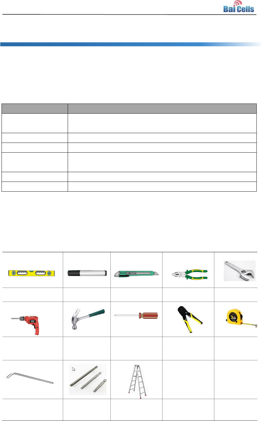
Installation Tools 3.2
The following tools are needed during the installation.
Level bar
Marking pen
Knife
Vise
Wrench
Percussion drill and
some drill heads
hammer
Cross screw
driver
Cable vice
Tape measure
5mm L-shape allen
wrench
T7 screwdriver
head
Ladder

Baicells mBS1105 Base Station Installation Guide(V100R001C00,02).docx
8
Installation Environment 3.3
3.3.1 Locational Requirements
Environments with high-temperatures, harmful gases, unstable voltages, volatile
vibrations, loud noises, flames, explosives, and electromagnetic interference (large radar
stations, transmitting stations, transformer substations) are not suitable for the operation
of mBS1105, and thus should be avoided.
Places prone to have impounded water, soaking, leakage, or condensation, should also
be avoided.
Factors like climate, hydrology, geology, earthquake, electric power, and transportation
should be taken into consideration in the construction process so that a proper location
can be chosen to meet the communication engineering environmental requirements, as
well as the technical requirements of network planning and communication equipment.
3.3.2 Environmental Requirements
Table 3-2 gives the base station’s environmental requirements with regards to
temperature, humidity, and voltage.
Table 3-2 Environmental Requirements of the Base Station
Item
Range
Typical value
Humidity
-40℃~ 55℃
25℃
Relative humidity (no condensation)
0% ~ 100%
5% ~ 95%
Safety voltage
42V ~ 58V
48V
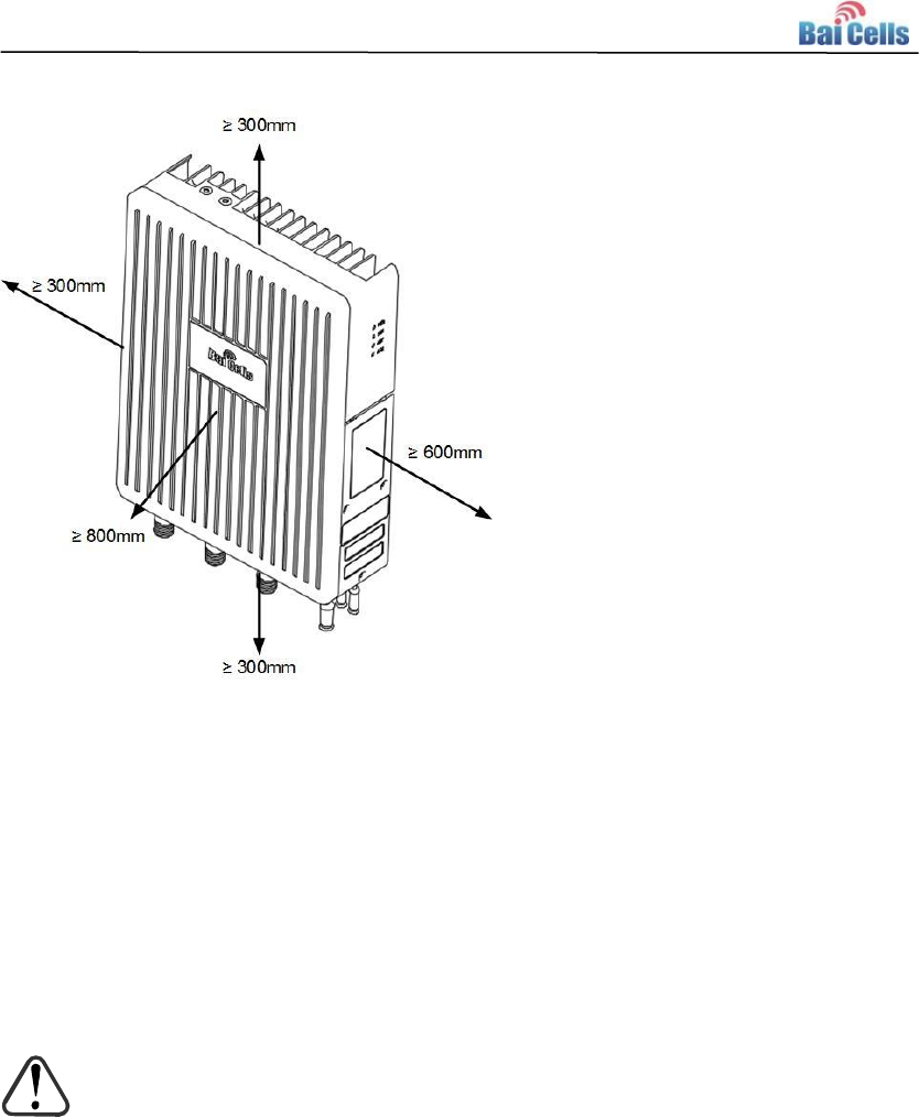
3.3.3 Space Requirements
After the eNodeB has installed, the enough space must be provided for operation and
maintenance. And for heat dissipation and normal running of the eNodeB, the space
must be planed before installation, as shown in Figure 3-1.
Baicells mBS1105 Base Station Installation Guide(V100R001C00,02).docx
9
Figure 3-1 Installation Space Requirement
Personnel Requirements 3.4
The installation personnel must master the basic safe operation knowledge, through the
training, and having the corresponding qualifications..
Lightening and Grounding Protection 3.5
CAUTION:
It is unlikely to happen but since the LTE eNodeB is very sophisticated equipment
so we would recommend you to test it on the ground to make sure everything is
functioning before install on the tower.
The operator must prepare external lightning protector to protect the GPS, external
antenna and RJ-45 port.
Grounding Notes:
The ground wire adopts yellow-green wire that is no smaller than 16 mm².
Grounding principle: as near as possible.
The eNodeB connects to the reliable outdoor grounding point (earth) through one
ground screw.
Baicells mBS1105 Base Station Installation Guide(V100R001C00,02).docx
10
The connection of the grounding points and the ground bar need to be tight and
reliable. Rustproofing the terminals is required. This can be done with rust
preventing paint, anti-oxidation coatings, grease, and so on.
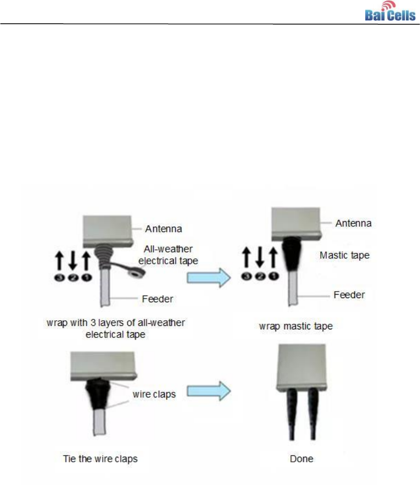
Weatherproof Protection 3.6
1. To weatherproof the connections, wrap them with all-weather electrical tape and
mastic tape, as shown in Figure 3-2.
Figure 3-2 Antenna Weatherproofing
2. Be aware that at least three layers of tapes are needed, and make sure that the
wrapping direction of the last layer is from the bottom up. The last layer should be
tight enough to keep it from cracking.
Baicells mBS1105 Base Station Installation Guide(V100R001C00,02).docx
11
4. Base Station Installation
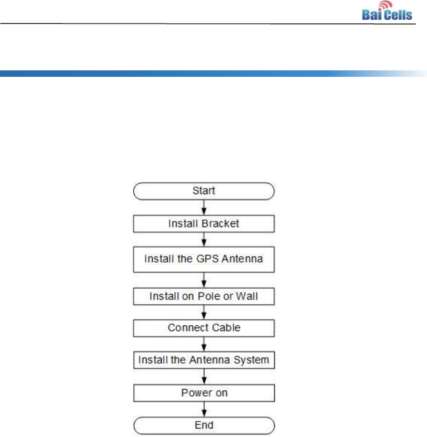
Installation Procedure 4.1
The installation procedure of mBS1105 is given in Figure 4-1.
Figure 4-1 Installation Procedure of mBS1105
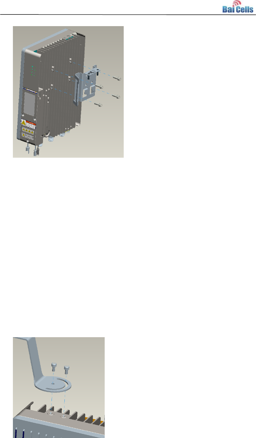
Install the Mounting Bracket and Handle 4.2
Using the M6*16 hex screw to fix the bracket on back side of the mBS1105, as shown in
Figure 4-2.
Baicells mBS1105 Base Station Installation Guide(V100R001C00,02).docx
12
Figure 4-2 Install the Mounting Bracket
Caution:
The arrow of the installation bracket must be upward.
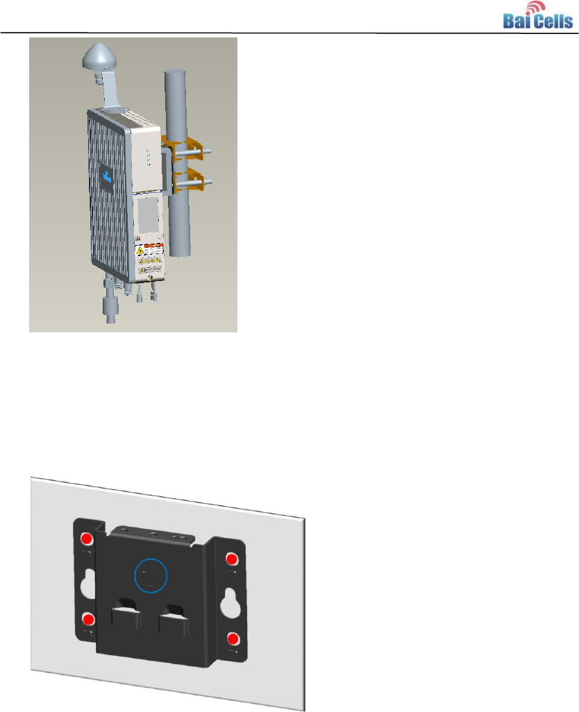
Install GPS Antenna 4.3
Installation requirements on the GPS antenna:
No major blocking from buildings in the vicinity. Keep the rooftop buildings a
distance away from the GPS. Make sure the space atop within 90 degrees (at least
45 degrees) is not blocked by any buildings.
Avoid installing the GPS in the vicinity of any other transmitting and receiving
devices. Avoid interference from other transmitting antennas to the GPS antennas.
Should be installed within 45 degrees to the lightning rod.
The following describes the steps of the GPS antenna installation.
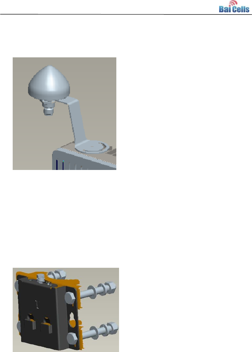
1. Using the M4*14 screws to fix the GPS mounting bracket on the base station.
Baicells mBS1105 Base Station Installation Guide(V100R001C00,02).docx
13
2. Pass the GPS antenna through the hole on the GPS mounting bracket.
3. Installation is complete.
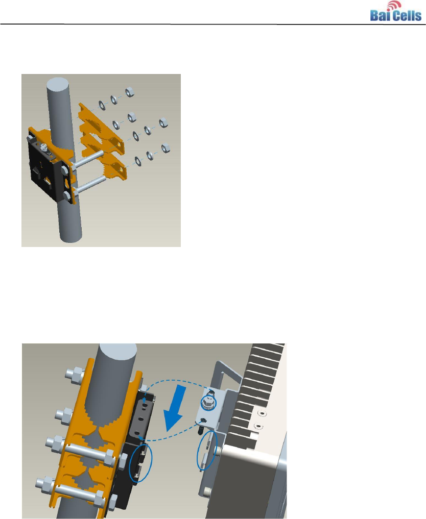
Install on Pole 4.4
Required diameter of the pole: 40mm ~ 100mm.
Suggest the installation height higher than 120cm, and the installation space
requirements meet the requirements in “3.3.3Space Requirements”.
1. As the following figure, assemble the bracket for pole installation, and fasten the four
nuts. .
Baicells mBS1105 Base Station Installation Guide(V100R001C00,02).docx
14
2. Make sure the installation height of the eNodeB, fit the thread rod of the assembled
bracket to the pole, and then pass the omega through the threaded rods, and fasten
the four nuts.
Caution:
The arrow of the installation bracket must be upward.
3. As the following figure, hung the two pin on the eNodeB bracket to the installation
bracket, push the eNodeB until the hook block to the eNodeB bracket
4. Fasten the screw on the top of the eNodeB bracket using cross screwdriver.
5. The installation is complete.
Baicells mBS1105 Base Station Installation Guide(V100R001C00,02).docx
15
Install on Wall 4.5
The wall must bear four times of the eNodeB weight.
1. Fit the base station on the wall, and mark the drilling locations.
Caution:
The arrow of the installation bracket must be upward.
2. Drill four 10mm diameter and 70mm depth holes in the wall by following the
marked locations.
3. Check the up/down direction of the installation rack, and then fix the eNodeB
to the wall using M8*80 expansion screws.
4. Refer to the installation steps on pole, fix the eNodeB on wall.
5. Fasten the screw on the top of the eNodeB bracket using cross screwdriver.

Baicells mBS1105 Base Station Installation Guide(V100R001C00,02).docx
16
6. The installation is complete.
Connect Cable 4.6
4.6.1 Requirement for Cable Laying
General requirements:
Bending radius requirement of feeder cable: 7/8” > 250mm, 4/5” > 380mm
Bending radius requirement of jumper cable: 1/4” > 35mm,1/2” (super soft) > 50mm,
1/2” (ordinary)>127mm
Bending radius requirement of power cable and grounding cable: > tripled of the
diameter of cable
The minimum bend radius of the optical fiber is the 20 times of the diameter of
optical fiber.
Binding the cables according the type of the cable, the intertwining and crossing is
forbidden.
The label should be paste after the cable laying.
Optical fiber laying requirement:
The circling and twisting is forbidden during the laying.
The binding on the turning is forbidden.
The pulling and weigh down the optical fiber is forbidden.
The redundant optical fiber must enwind the dedicated device.
Grounding laying requirement:
The grounding cable must connect to the grounding point.
The grounding cable must be separate with the signal cables, remaining a certain
distance to avoid the interruption of signal.
4.6.2 Connect GPS Antenna
1. Connect one end of the GPS RF cable to the GPS antenna. It is necessary for the
GPS antenna interfaces to be weatherproofed. Refer to 3.6 Weatherproof Protection
for more detail.
2. Connect the other end of the GPS RF cable to the GPS interface of the eNodeB,
which also need the weatherproof protection.

Baicells mBS1105 Base Station Installation Guide(V100R001C00,02).docx
17
4.6.3 Connect RF Cable
1. Open the dust cap of ANT0 and ANT1 interface.
2. Connect one end of the RF cable to ANT0 and ANT1 interface of the eNodeB and
fasten them with wrench.
3. Connect the other end of the RF cable to the external antenna.
4. It is necessary for ANT0 and ANT1 interfaces to be weatherproofed. Refer to 3.6
Weatherproof Protection for more detail.
4.6.4 Connect Optical Fiber
1. Unscrew three screws on the cover of wiring cavity using M4 cross screwdriver and
open the wiring cavity.
2. Connect the optical fiber to the OPT interface in the wiring cavity.
3. Lay optical fibers along the wire groove, and stretch out the wiring cavity from the
OPT hole.
The redundant fiber should wind neatly.
4.6.5 Connect Ethernet Cable
1. Connect the Ethernet cable to the ETH interface in the wiring cavity.
2. Lay Ethernet cable along the wire groove, and stretch out the wiring cavity from the
ETH hole.
4.6.6 Connect Power Connector
Make the power cable so it can reach the distance between the installation site and the
power supply device. Strip the 12mm insulating layer with wire stripper, which is inserted
into the power connector.
It is recommended that the power cord length is kept below 100m (330 feet).
The connection steps of power cable is as follows.
1. Connect the power cable to the PWR interface in the wiring cavity.
2. The power cable lays along the lint slot, and stretch out the wiring cavity from the
PWR hole
3. The input of the power adaptor connects to the outlet.
Baicells mBS1105 Base Station Installation Guide(V100R001C00,02).docx
18
If the outlet is indoors, place the power adaptor indoors.
If the outlet is outdoors, place the power adaptor in a water proof box.
4. After the cable connection is complete in the wiring cavity, fasten the screws on the
cover to close the wiring cavity using M4 cross screwdriver.
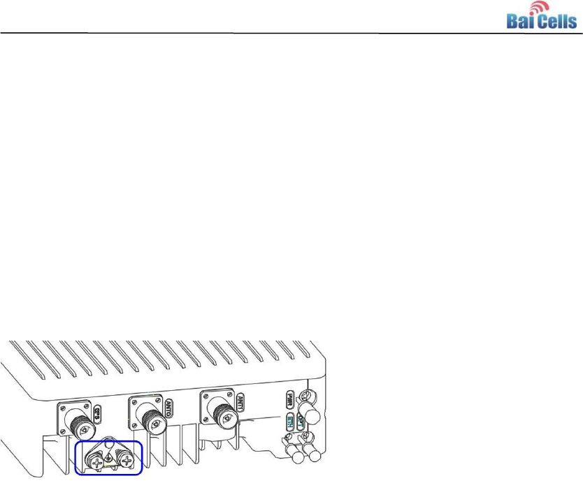
4.6.7 Connect Ground Cable
Make the grounding cable according the actual situation of the installation site.
The mBS1105 provides two grounding screws, which is located on the bottom of the
base station, as shown in Figure 4-3.
Figure 4-3 Location of Grounding Screws
1. Unscrew one grounding screw, connect one end of the grounding cable to the
grounding screw, and fasten it again.
2. The other end of the ground cable needs to connect to a good grounding point.
Install Antenna Feeder System 4.7
There are two kinds of outdoor antennas, omnidirectional outdoor antennas and
directional outdoor antennas, whose installation will be introduced in the following,
respectively.
4.7.1 Install Omnidirectional Antennas
One should pay attention to the followings while installing the omnidirectional outdoor
antenna:
The diameter of the pole for omnidirectional outdoor antennas is required to be
35mm ~ 50mm. A typical case is to use the 50mm-diameter round-steel-made pole
(with details depending on the specific antenna type).
Make sure that the top of pole and the clamp beneath the antenna are at the same
level, after installing the omnidirectional outdoor antenna on the pole.
Baicells mBS1105 Base Station Installation Guide(V100R001C00,02).docx
19
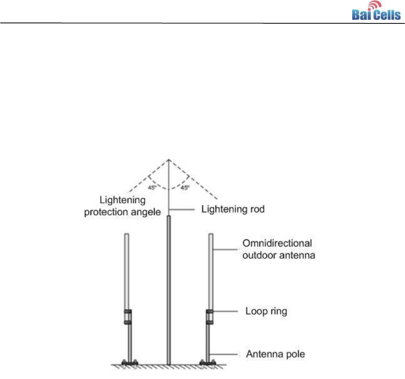
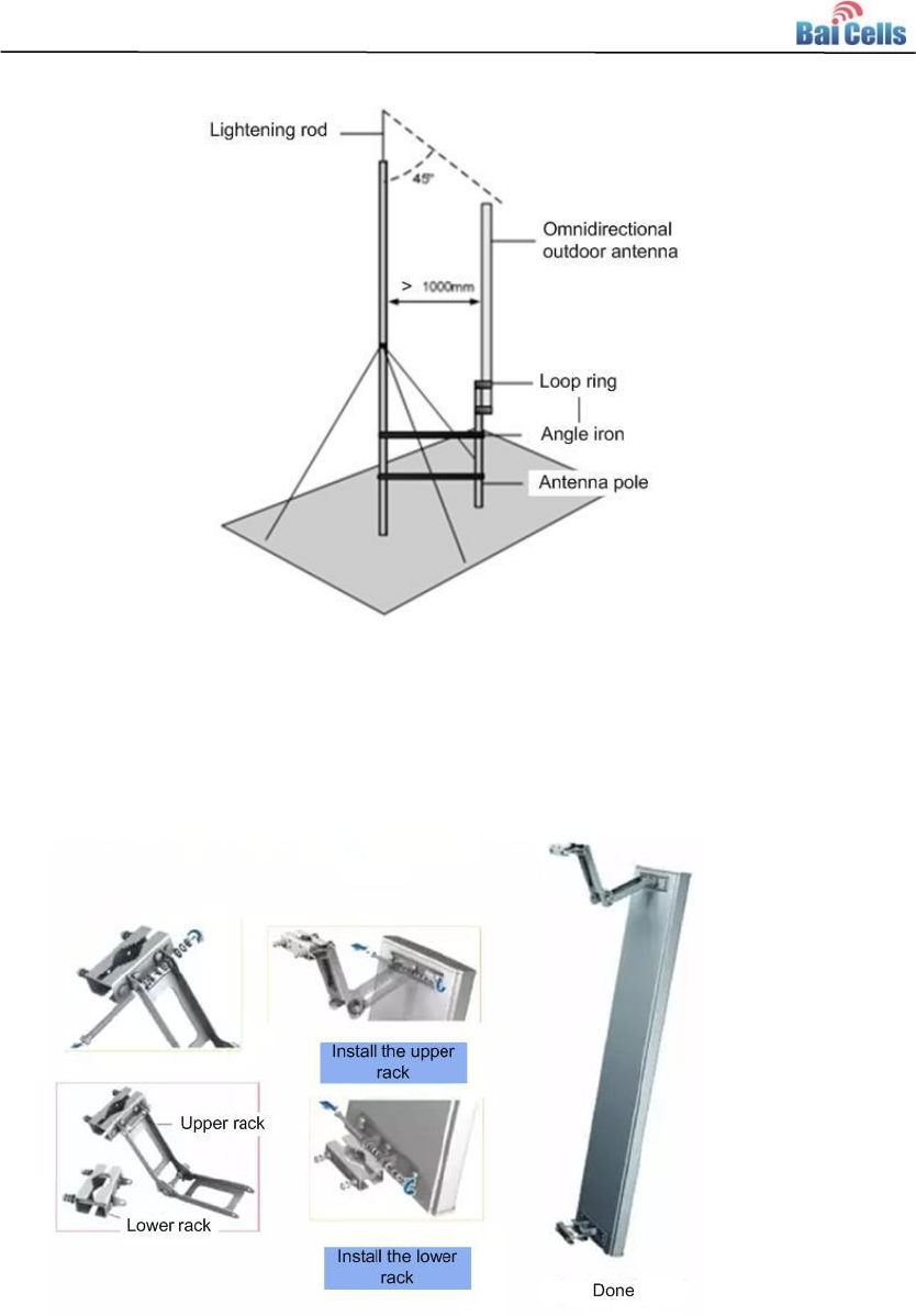
Make sure that the antenna is high enough to meet the coverage requirement, and
that the antenna top falls within the 45 degrees safety angle towards the lightening
rod, as shown in Figure 4-4. In principle, no lightening rod can be welded to pole (no
metal object is allowed within 1m of the horizontal direction of the omnidirectional
antennas), when installing the omnidirectional antennas. Instead, an independent
lightening rod should be settled between the two poles, where the lightening rod
must be high enough to keep all antennas under its protection cover.
Figure 4-4 Omnidirectional Antenna Installation (1)
In case is impossible to install an independent lightning rod due to environmental
limitations, the installation method shown in Figure 4-5 can be used. Be aware that the
pole supporting the lightening rod should be kept at least 1m away from the
omnidirectional outdoor antennas.
Baicells mBS1105 Base Station Installation Guide(V100R001C00,02).docx
20
Figure 4-5 Omnidirectional Antenna Installation (2)
4.7.2 Install Directional Antennas
1. First, assemble the antennas, as shown in Figure 4-6.
Figure 4-6 Assembling Procedure of Directional Antennas
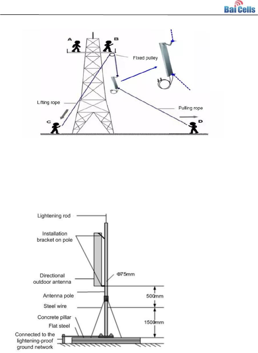
2. To install it on the iron tower, use a pulley to transport the antenna assembled to the
platform on the iron tower, as shown in Figure 4-7. Following the safety rules when
working at these heights.
Baicells mBS1105 Base Station Installation Guide(V100R001C00,02).docx
21
Figure 4-7 Transportation the Antennas in the Height
3. Fix the pole vertically to the ground or concrete pillars on the rooftop using
expansion screws, and fasten it with steel wires. Then, mount the directional
outdoor antenna onto the pole using the installation rack, as shown in Figure 4-8.
Figure 4-8 Directional Antenna Installation
4. When the base station has been installed in a proper position, connect all the cables
and wires.
5. Run tests, then seal and weatherproof all the connections after the testing has
successfully completed. Refer to 3.6 Weatherproof Protection.
Baicells mBS1105 Base Station Installation Guide(V100R001C00,02).docx
22
5. Power On
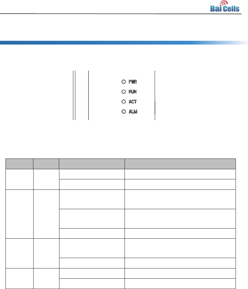
Power on the mBS1105, and the indicators will light up, as shown in Figure 5-1.
Figure 5-1 LED Indicators
The explanation of the indicator signal is given in Table 5-1.
Table 5-1 mBS1105 Indicator Description
Type
Color
Status
Meaning
PWR
Green
ON
Have power input
OFF
No power input
RUN
Green
Fast blink: 0.125s on,
0.125s off
Single board loading
Slow blink: 1s on, 1s
OFF
Single board running well
OFF
No power input, or single board failure
ALM
Red
ON
Hardware warning status, e.g., cable
connection failure warning
OFF
No warning
ACT
Green
ON
Active cell
OFF
Inactive cell

Baicells mBS1105 Base Station Installation Guide(V100R001C00,02).docx
23
Additional Information Appendix A
A.1 Antenna Information
The following is a list of antennas that are certified for use. Customers can choose
different antennas according to the environment.
Table 5-2 Antenna Information
Antenna Type
Manufacturer
Model Number
Antenna Max
Gain(dBi)
External Planar
Antenna Dual Pole
Kenbotong Technology
Co., Ltd.
KBT90DP13-3338
AT0
13
External Planar
Antenna Dual Pole
Kenbotong Technology
Co., Ltd.
KBT90DP14-3338
AT0
14
External Planar
Antenna Dual Pole
Baicells Technologies
Co., Ltd
ANT-3G11-R-65-E
DT0
11
External Planar
Antenna Dual Pole
Baicells Technologies
Co., Ltd
ANT-3G7-R-65-ED
T0
7
External
Omnidirectional
Antenna Single Pole
Kenbotong Technology
Co., Ltd.
TQJ-3500AC6
6
External
Omnidirectional
Antenna Single Pole
Kenbotong Technology
Co., Ltd.
TQJ-3500AC3
3
External
Omnidirectional
Antenna Single Pole
Kenbotong Technology
Co., Ltd.
TQJ-3500AT8
8

Baicells mBS1105 Base Station Installation Guide(V100R001C00,02).docx
24
A.2 Maximum Output Power
The maximum output power can be set as follows:
Antenna Max
Gain (dBi)
10Log(Number
of antennas)
Channel BW
(MHz)
Max output
power
(dBm)
EIRP
(dBm)
13
3
10
23
39
20
23
39
14
10
22
39
20
22
39
11
10
25
39
20
25
39
7
10
29
39
20
29
40
6
10
30
39
20
30
39
3
10
33
39
20
33
39
8
10
28
39
20
28
39
A.3 Regulatory Compliance
FCC Compliance
This device complies with part 15 of the FCC Rules. Operation is subject to the
following two conditions: (1) This device may not cause harmful interference, and (2)
this device must accept any interference received, including interference that may
cause undesired operation.
Any Changes or modifications not expressly approved by the party responsible for
compliance could void the user's authority to operate the equipment.
This equipment has been tested and found to comply with the limits for a Class A

Baicells mBS1105 Base Station Installation Guide(V100R001C00,02).docx
25
digital device, pursuant to part 15 of the FCC Rules. These limits are designed to
provide reasonable protection against harmful interference when the equipment is
operated in a commercial environment. This equipment generates, uses, and can
radiate radio frequency energy and, if not installed and used in accordance with the
instruction manual, may cause harmful interference to radio communications.
Operation of this equipment in a residential area is likely to cause harmful
interference in which case the user will be required to correct the interference at his
own expense.
Warning
This equipment complies with FCC radiation exposure limits set forth for an
uncontrolled environment. This equipment should be installed and operated with
minimum distance 30 cm between the radiator & your body.
ISEDC Compliance
This device complies with Innovation, Science, and Economic Development
Canada licence-exempt RSS standard(s).
Operation is subject to the following two conditions: (1) This device may not cause i
nterference, and (2) This device must accept any interference, including interferenc
e that may cause undesired operation of the device.
Le présent appareil est conforme aux CNR d' Innovation, Science et
Développement
économique Canada applicables aux appareils radio exempts de licence.
L'exploitation est autorisée aux deux conditions
suivantes:
(1) l'appareil ne doit pas produire de brouillage, et
(2) l'utilisateur de l'appareil doit accepter tout brouillage radioélectrique subi,
même si le brouillage est susceptible d'en compromettre le fonctionnement.
The antenna(s) used for this transmitter must be installed to provide a separation
distance of at least 30 cm from all persons and must not be collocated or operating
in conjunction with any other antenna or transmitter, End-Users must be provided
with transmitter operation conditions for satisfying RF exposure compliance.