Baldor TS400 User Manual To The 781a7e03 3340 41a9 Aff6 168450023f05
User Manual: Baldor TS400 to the manual
Open the PDF directly: View PDF ![]() .
.
Page Count: 80
TS400 Sine Wave Inverter
Owner’s Guide

TS400 Sine Wave Inverter
Owner’s Guide
$ERXW;DQWUH[
Xantrex Technology Inc. is a world-leading supplier of advanced power electronics and controls with products from
50 watt mobile units to one MW utility-scale systems for wind, solar, batteries, fuel cells, microturbines, and backup
power applications in both grid-connected and stand-alone systems. Xantrex products include inverters, battery
chargers, programmable power supplies, and variable speed drives that convert, supply, control, clean, and distribute
electrical power.
7UDGHPDUNV
TS400 Sine Wave Inverter is a trademark of Xantrex International. Xantrex is a registered trademark of Xantrex
International.
Other trademarks, registered trademarks, and product names are the property of their respective owners and are used
herein for identification purposes only.
1RWLFHRI&RS\ULJKW
TS400 Sine Wave Inverter Owner’s Guide © July 2003 Xantrex International. All rights reserved.
'LVFODLPHU
UNLESS SPECIFICALLY AGREED TO IN WRITING, XANTREX TECHNOLOGY INC. (“XANTREX”)
(a) MAKES NO WARRANTY AS TO THE ACCURACY, SUFFICIENCY OR SUITABILITY OF ANY
TECHNICAL OR OTHER INFORMATION PROVIDED IN ITS MANUALS OR OTHER DOCUMENTATION.
(b) ASSUMES NO RESPONSIBILITY OR LIABILITY FOR LOSS OR DAMAGE, WHETHER DIRECT,
INDIRECT, CONSEQUENTIAL OR INCIDENTAL, WHICH MIGHT ARISE OUT OF THE USE OF SUCH
INFORMATION. THE USE OF ANY SUCH INFORMATION WILL BE ENTIRELY AT THE USER’S RISK.
'DWHDQG5HYLVLRQ
July 2003 Revision A
3DUW1XPEHU
975-0055-01-01
&RQWDFW,QIRUPDWLRQ
Telephone: 1-800-670-0707 (toll free in North America)
1-604-422-2777 (direct)
Fax: 1-604-420-2145
Email: CustomerService@xantrex.com
Web: www.xantrex.com

975-0055-01-01 iii
About This Guide
Purpose
The TS400 Sine Wave Inverter Owner’s Guide contains information for
installing, operating, and troubleshooting the TS400 Sine Wave Inverter
(TS400).
Scope
This Guide provides safety guidelines, installation, operation,
troubleshooting, and warranty information for the TS400.
Basic information on battery types and sizes is provided in Appendix B,
“Battery Types and Sizes”. For comprehensive information about your
battery, refer to the battery manufacturer’s guide.
Service information is not included as the unit does not contain user-
serviceable parts.
Audience
This Guide is intended for anyone who needs to install and operate the
TS400 Sine Wave Inverter. Installers should be certified technicians or
electricians.
Organization
The Owner’s Guide is organized into four chapters and two appendixes.
Chapter 1, “Introduction”, outlines the main performance and safety
features of the TS400. Reading this chapter will give you a clear
understanding of the inverter’s capabilities.
Chapter 2, “Installation”, provides detailed information for installing the
TS400.
About This Guide
iv 975-0055-01-01
Chapter 3, “Operation”, provides information about operating the TS400.
Details are provided on how to read the front panel indicators to monitor
the TS400.
Chapter 4, “Troubleshooting”, explains how to identify and solve
problems that can occur with the TS400.
Appendix A, “Specifications”, provides the electrical and physical
specifications of the TS400.
Appendix B, “Battery Types and Sizes”, provides information that will
help you to select, connect, and maintain batteries that are most
appropriate for your application.
“Warranty and Product Information”, contains the product warranty,
explains how to return a product for service, and describes how to prepare
for a call to Xantrex Customer Service.
Conventions Used
The following conventions are used in this guide.
WARNING
Warnings identify conditions that could result in personal
injury or loss of life.
CAUTION
Cautions identify conditions or practices that could result in
damage to the TS400 Sine Wave Inverter or to other
equipment.
Note: Notes describe additional information which may add to
your understanding of how to use the TS400.
Important:
These notes describe an important action item or an
item that you must pay attention to.

About This Guide
975-0055-01-01 v
Acronyms and Terminology
Related Information
You can find more information about Xantrex Technology Inc. as well as
its products and services at www.xantrex.com
AC Alternating current
DC Direct current
CSA Canadian Standards Association
FCC Federal Communications Commission
GFCI Ground fault circuit interrupter
UL Underwriters Laboratories Inc.
Hardwiring to make a permanent electrical connection
vi
975-0055-01-01 vii
Important Safety Instructions
General Precautions
1. Before installing and using the inverter, read all appropriate sections
of this guide and any cautionary markings on the inverter and the
batteries.
2. Do not operate the inverter if it has received a sharp blow, been
dropped, or otherwise damaged. If the unit is damaged, see “Warranty
and Product Information” on page WA–1.
3. Do not dismantle the inverter; it contains no user-serviceable parts.
Attempting to service the unit yourself could cause electrical shock or
fire. Internal capacitors remain charged after all power is
disconnected. See “Warranty” on page WA–1 for instructions on
obtaining service.
WARNING
This Owner’s Guide contains important safety and operating
instructions.
Before using your TS400 Sine Wave Inverter, be sure to read,
understand, and save these safety instructions.
WARNING: Restrictions on Use
The TS400 Sine Wave Inverter shall not be used in connection
with life support systems or other medical equipment or
devices.
WARNING: Shock hazard
The TS400 has On/Standby mode only. It does not have an Off
mode, that is, DC power is permanently connected to the unit.
Important Safety Instructions
viii 975-0055-01-01
4. To reduce the risk of electrical shock, disconnect DC power from the
inverter before working on any circuits connected to the inverter.
Turning the On/Standby switch to Standby ( ) will not reduce this
risk.
5. Protect the inverter from rain, snow, spray, and water.
6. To reduce the risk of overheating, keep the ventilation openings clear,
and do not install the inverter in a compartment with limited airflow.
Precautions When Working With Batteries
1. To reduce the risk of battery explosion, follow all instructions
published by the battery manufacturer and the manufacturer of the
equipment in which the battery is installed.
2. Make sure the area around the battery is well ventilated.
3. Never smoke or allow a spark or flame near the engine or batteries.
4. Use caution to reduce the risk of dropping a metal tool on the battery.
It could spark or short circuit the battery or other electrical parts and
could cause an explosion.
Explosive Gas Precautions
1. Batteries generate explosive gases during normal operation. Be sure
you follow all relevant instructions exactly before installing or using
your inverter.
2. This equipment contains components which tend to produce arcs or
sparks. To prevent fire or explosion, do not install the inverter in
compartments containing batteries or flammable materials or in
locations that require ignition-protected equipment. This includes any
space containing gasoline-powered machinery, fuel tanks, as well as
joints, fittings, or other connections between components of the fuel
system.
WARNING: Explosion and Fire Hazard

Important Safety Instructions
975-0055-01-01 ix
FCC Information to the User
This Class B device complies with Part 15 of the FCC Rules and all
requirements of the Canadian Interference-Causing Equipment
Regulations. Operation is subject to the following two conditions: (1) this
device may not cause harmful interference, and (2) this device must
accept any interference received, including interference that may cause
undesired operation.
x

975-0055-01-01 xi
Important Safety Instructions
General Precautions - - - - - - - - - - - - - - - - - - - - - - - - - - - - - - - - - - - - - - - - - - - - - - - - vii
Precautions When Working With Batteries - - - - - - - - - - - - - - - - - - - - - - - - - - - - - - - - viii
Explosive Gas Precautions - - - - - - - - - - - - - - - - - - - - - - - - - - - - - - - - - - - - - - - - - - - viii
FCC Information to the User - - - - - - - - - - - - - - - - - - - - - - - - - - - - - - - - - - - - - - - - - - -ix
1
Introduction
How TS400 Works - - - - - - - - - - - - - - - - - - - - - - - - - - - - - - - - - - - - - - - - - - - - - - - -1–2
Premium Power and Ease of Use - - - - - - - - - - - - - - - - - - - - - - - - - - - - - - - - - - - - - - -1–2
Comprehensive Protection - - - - - - - - - - - - - - - - - - - - - - - - - - - - - - - - - - - - - - - - - - -1–3
TS400 Features- - - - - - - - - - - - - - - - - - - - - - - - - - - - - - - - - - - - - - - - - - - - - - - - - - -1–4
Front Panel - - - - - - - - - - - - - - - - - - - - - - - - - - - - - - - - - - - - - - - - - - - - - - - - - - -1–4
Back Panel - - - - - - - - - - - - - - - - - - - - - - - - - - - - - - - - - - - - - - - - - - - - - - - - - - -1–5
Optional Accessory: Remote Switch - - - - - - - - - - - - - - - - - - - - - - - - - - - - - - - - - - - -1–6
Dimensions of Remote Switch - - - - - - - - - - - - - - - - - - - - - - - - - - - - - - - - - - - - - -1–6
Part number of Remote Switch - - - - - - - - - - - - - - - - - - - - - - - - - - - - - - - - - - - - -1–6
2
Installation
Introduction - - - - - - - - - - - - - - - - - - - - - - - - - - - - - - - - - - - - - - - - - - - - - - - - - - - - -2–2
Preparing for Installation - - - - - - - - - - - - - - - - - - - - - - - - - - - - - - - - - - - - - - - - - - - -2–3
Installation Codes - - - - - - - - - - - - - - - - - - - - - - - - - - - - - - - - - - - - - - - - - - - - - -2–3
Materials List - - - - - - - - - - - - - - - - - - - - - - - - - - - - - - - - - - - - - - - - - - - - - - - - -2–4
Installation Tools and Materials - - - - - - - - - - - - - - - - - - - - - - - - - - - - - - - - - - - - -2–4
Installing the TS400 - - - - - - - - - - - - - - - - - - - - - - - - - - - - - - - - - - - - - - - - - - - - - - -2–6
Overview - - - - - - - - - - - - - - - - - - - - - - - - - - - - - - - - - - - - - - - - - - - - - - - - - - - -2–6
Step 1: Designing Your Installation - - - - - - - - - - - - - - - - - - - - - - - - - - - - - - - - - -2–6
Step 2: Mounting Your Inverter - - - - - - - - - - - - - - - - - - - - - - - - - - - - - - - - - - - -2–10
Step 3: Connecting the Chassis Ground - - - - - - - - - - - - - - - - - - - - - - - - - - - - - - -2–11
Step 4: Installing the Optional S400 Remote Switch - - - - - - - - - - - - - - - - - - - - - -2–12
Step 5: Getting Ready to Connect the DC Cables - - - - - - - - - - - - - - - - - - - - - - - -2–14
Step 6: Routing the DC Cables - - - - - - - - - - - - - - - - - - - - - - - - - - - - - - - - - - - -2–15
Step 7: Connecting the DC Cables - - - - - - - - - - - - - - - - - - - - - - - - - - - - - - - - - -2–16
Step 8: Connecting Your Equipment to the GFCI Outlets - - - - - - - - - - - - - - - - - - -2–18
Step 9: Hardwiring the AC Output - - - - - - - - - - - - - - - - - - - - - - - - - - - - - - - - - -2–19
Step 10: Performing Checks Prior to Initial Start-up - - - - - - - - - - - - - - - - - - - - - -2–22
Step 11: Testing Your Installation - - - - - - - - - - - - - - - - - - - - - - - - - - - - - - - - - -2–22
Contents

Contents
xii 975-0055-01-01
3
Operation
Front Panel Features- - - - - - - - - - - - - - - - - - - - - - - - - - - - - - - - - - - - - - - - - - - - - - - 3–2
Operating the TS400 - - - - - - - - - - - - - - - - - - - - - - - - - - - - - - - - - - - - - - - - - - - - - - 3–3
Turning the TS400 On - - - - - - - - - - - - - - - - - - - - - - - - - - - - - - - - - - - - - - - - - - - 3–3
Turning the TS400 to Standby When Not in Use - - - - - - - - - - - - - - - - - - - - - - - - - 3–3
Using the Optional S400 Remote Switch - - - - - - - - - - - - - - - - - - - - - - - - - - - - - - 3–4
Recharging Your Batteries - - - - - - - - - - - - - - - - - - - - - - - - - - - - - - - - - - - - - - - - - - 3–5
Recovering from Low Battery Voltage Shutdown - - - - - - - - - - - - - - - - - - - - - - - - 3–5
Restarting or Operating Multiple Pieces of Equipment - - - - - - - - - - - - - - - - - - - - - 3–5
Monitoring the Operating Status- - - - - - - - - - - - - - - - - - - - - - - - - - - - - - - - - - - - - - - 3–6
Resetting After a Fault or Shutdown - - - - - - - - - - - - - - - - - - - - - - - - - - - - - - - - - - - - 3–7
4
Troubleshooting
Troubleshooting Reference - - - - - - - - - - - - - - - - - - - - - - - - - - - - - - - - - - - - - - - - - - 4–2
A
Specifications
Electrical Specifications - - - - - - - - - - - - - - - - - - - - - - - - - - - - - - - - - - - - - - - - - - - -A–2
Physical Specifications with Projections - - - - - - - - - - - - - - - - - - - - - - - - - - - - - - - - -A–2
Regulatory Approvals- - - - - - - - - - - - - - - - - - - - - - - - - - - - - - - - - - - - - - - - - - - - - -A–3
Fan Cooling System - - - - - - - - - - - - - - - - - - - - - - - - - - - - - - - - - - - - - - - - - - - - - - -A–3
B
Battery Types and Sizes
Battery Types - - - - - - - - - - - - - - - - - - - - - - - - - - - - - - - - - - - - - - - - - - - - - - - - - - - B–2
Automotive Starting Batteries - - - - - - - - - - - - - - - - - - - - - - - - - - - - - - - - - - - - - - B–2
Deep-Cycle Batteries - - - - - - - - - - - - - - - - - - - - - - - - - - - - - - - - - - - - - - - - - - - B–2
Battery Size - - - - - - - - - - - - - - - - - - - - - - - - - - - - - - - - - - - - - - - - - - - - - - - - - - - - B–3
Estimating Battery Requirements - - - - - - - - - - - - - - - - - - - - - - - - - - - - - - - - - - - - - -B–4
Battery Sizing Example - - - - - - - - - - - - - - - - - - - - - - - - - - - - - - - - - - - - - - - - - -B–4
Battery Sizing Worksheet - - - - - - - - - - - - - - - - - - - - - - - - - - - - - - - - - - - - - - - -B–5
Using Multiple Batteries - - - - - - - - - - - - - - - - - - - - - - - - - - - - - - - - - - - - - - - - - - - - B–6
Two Batteries Connected In Parallel - - - - - - - - - - - - - - - - - - - - - - - - - - - - - - - - -B–6
Two Separate Battery Banks - - - - - - - - - - - - - - - - - - - - - - - - - - - - - - - - - - - - - - - B–6
Battery Tips - - - - - - - - - - - - - - - - - - - - - - - - - - - - - - - - - - - - - - - - - - - - - - - - - - - - B–7
Warranty and Product Information
- - - - - - - - - - - - - - - - - - - - - - - - - - - - - WA–1
Warranty - - - - - - - - - - - - - - - - - - - - - - - - - - - - - - - - - - - - - - - - - - - - - - - - - - - - WA–1
Disclaimer - - - - - - - - - - - - - - - - - - - - - - - - - - - - - - - - - - - - - - - - - - - - - - - - - - - WA–2
Product - - - - - - - - - - - - - - - - - - - - - - - - - - - - - - - - - - - - - - - - - - - - - - - - - - - WA–2

Contents
975-0055-01-01 xiii
Exclusions - - - - - - - - - - - - - - - - - - - - - - - - - - - - - - - - - - - - - - - - - - - - - - - - -WA–2
Warning: Limitations On Use - - - - - - - - - - - - - - - - - - - - - - - - - - - - - - - - - - - -WA–2
Return Material Authorization Policy- - - - - - - - - - - - - - - - - - - - - - - - - - - - - - - - - -WA–3
Return Procedure - - - - - - - - - - - - - - - - - - - - - - - - - - - - - - - - - - - - - - - - - - - - - - -WA–3
Out of Warranty Service - - - - - - - - - - - - - - - - - - - - - - - - - - - - - - - - - - - - - - - - - -WA–3
Information About Your System - - - - - - - - - - - - - - - - - - - - - - - - - - - - - - - - - - - - -WA–4
Index
- - - - - - - - - - - - - - - - - - - - - - - - - - - - - - - - - - - - - - - - - - - - - - - - - - - - - - - - - -IX–1
xiv

Introduction
Congratulations on your purchase of the Xantrex TS400 Sine
Wave Inverter!
The TS400 has been designed to give you premium power,
ease of use, and outstanding reliability.
Please read this chapter to familiarize yourself with the main
performance and protection features of the TS400.
To ensure quality customer service for your inverter, be sure to
keep your proof of purchase. Also, take a few minutes at this
time to complete the form, “Information About Your System”
on page WA–4.

Introduction
1–2 975-0055-01-01
How TS400 Works
TS400 is a sine wave inverter which converts 12 volts direct-current (DC)
power from your battery to 120 volts alternating current (AC) power. This
AC power is the same as the electricity you get from your utility. In terms
of output, TS400 provides 400 watts of sine wave power for operating
your equipment.
Premium Power and Ease of Use
TS400 provides premium power for your portable power needs. The
inverter’s sine wave output provides clean power for small power tools,
test equipment, television monitors and battery chargers.
Superior features and rugged durability have been combined with ease of
use:
•400 watt inverter with 800 watt surge
•Filtered sine wave output will not cause distortion on sensitive
electronics
•DSP control technology starts complex loads with ease
•Two GFCI outlets and hardwire AC connections
•Easy-to-read indicator lights on the front panel
•Optional S400 Remote Switch provides On/Standby control from a
convenient location
•Audible alarm for low battery voltage
•Automatic cooling fan

Comprehensive Protection
975-0055-01-01 1–3
Comprehensive Protection
TS400 is designed to meet UL 458 and CSA C22.2 No. 107.1 safety
standards and it is compliant with FCC Class B.
TS400 comes equipped with numerous protection features to guarantee
you safe and worry-free operation.
3URWHFWLRQIHDWXUH 7KLVSURWHFWLRQIHDWXUH«
Low voltage alarm and
shutdown Protects the battery from becoming completely discharged. The
Low Battery light and audible alarm indicate that input voltage is
low (10.7 volts). If the input voltage drops below 10.3 volts, the
TS400 shuts down automatically and the Inverter ON light turns
off. The TS400 recovers automatically when the input voltage
comes up to about 12.6 volts.
High voltage shutdown Protects the TS400 by disabling the AC output when the input
voltage rises to 15.3 volts or more. The AC output is enabled when
the input voltage drops to 14.5 volts.
Over-temperature
shutdown Disables the AC output of the TS400 when the internal temperature
rises to unacceptable levels due to higher ambient temperature or
overloading. The TS400 recovers automatically when it cools
down.
Overload protection Disables the AC output of the TS400 if the appliance connected to
the inverter exceeds the 400 watt rating of the inverter. The TS400
will have to be reset. (See “Resetting After a Fault or Shutdown” on
page 3–7.)
Supplemental circuit
protection Trips and disables the AC output when a current in excess of 7.5
amps is drawn from the TS400. The supplemental circuit protector
can be reset to enable the unit to operate again after clearing the
overload condition. (See “Resetting After a Fault or Shutdown” on
page 3–7.)
Short circuit protection Disables the AC output of the TS400 when a short circuit is applied
on the AC output. Once the short circuit is cleared, the TS400 will
have to be reset. (See “Resetting After a Fault or Shutdown” on
page 3–7.)
Ground fault circuit
interrupter (GFCI) Trips and disables the output of the TS400 when a ground fault
current is detected. The output can be enabled again by resetting the
GFCI, once the ground fault is cleared. (See “Ground Fault” on
page 3–7.)
Introduction
1–4975-0055-01-01
TS400 Features
Front Panel
\
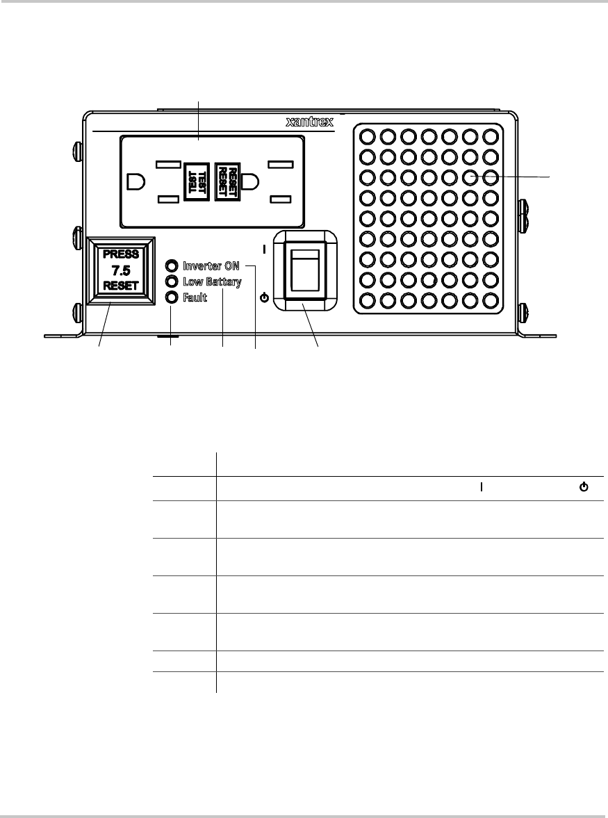
Figure 1-1
Front Panel of the TS400
Table 1-1
Front Panel Features
)HDWXUH 'HVFULSWLRQ
1On/Standby Switch turns the inverter to On ( ) or to Standby ().
2Inverter ON light illuminates when the TS400 is powering
equipment from the battery.
3Low Battery light illuminates when your battery voltage is lower
than 10.7 volts.
4Fault light illuminates for fault conditions such as over
temperature, output overload, or battery over voltage.
5Supplemental Circuit Protection button trips if there is an over-
current (over 7.5 amps) or a short circuit.
6GFCI outlets for connecting your equipment.
7Ventilation openings provide air circulation for peak performance.
21
3
54
6
7
TS400 Features
975-0055-01-01 1–5
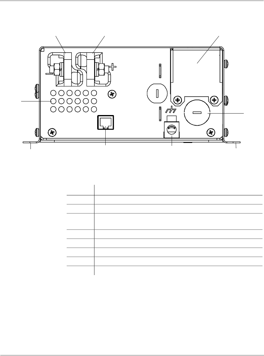
Back Panel
Figure 1-2
Back Panel of the TS400
Table 1-2
Back Panel Features
)HDWXUH 'HVFULSWLRQ
1 DC terminal, negative
2 DC terminal, positive
3 Wiring box access panel (For a view with the panel removed, see
“Completing the Hardwiring” on page 2–21.)
4 Knockout for AC output hardwiring
5 Chassis ground lug
6 Jack for optional remote switch
7 Mounting flanges
8 Ventilation openings provide air circulation.
12 3
4
5
67
8
7

Introduction
1–6975-0055-01-01
Optional Accessory: Remote Switch
An optional remote switch can be plugged into the remote switch jack at
the back of the TS400. It lets you switch the TS400 from on to standby
from a convenient location—up to 25 feet (7.5 m) away from the inverter
(using the cable supplied with the switch).
Dimensions of Remote Switch
Part number of Remote Switch
To purchase a remote switch, please contact Customer Service for a
referral to a distributor. Please provide the part number 808-2400. See
page ii for contact information.
+HLJKW 2.5 inches (63.5 mm)
:LGWK 2 inches (50.8 mm)
'HSWK 1.1 inches (28.3 mm)
&DEOHOHQJWK 25 feet (7.5 m)
Note: The remote switch jack at the back of the TS400 may not be
accessible once the inverter has been mounted.
If you intend to use the remote switch with an TS400 that has already
been installed, consult a qualified service technician before installing
and connecting the remote switch.
Installation
Chapter 2, “Installation”, provides detailed information for
installing the TS400 and the optional S400 Remote Switch.
This chapter provides:
•a system diagram
•safety instructions and installation codes that must be
observed during installation
•a list of installation tools and materials
•detailed installation procedures
•chassis ground and DC cabling information
•procedures for hardwiring the AC output
•an illustration of inverter dimensions
CAUTION
Be sure to read all instructions before installing and operating
the TS400.
Installation
2–2975-0055-01-01
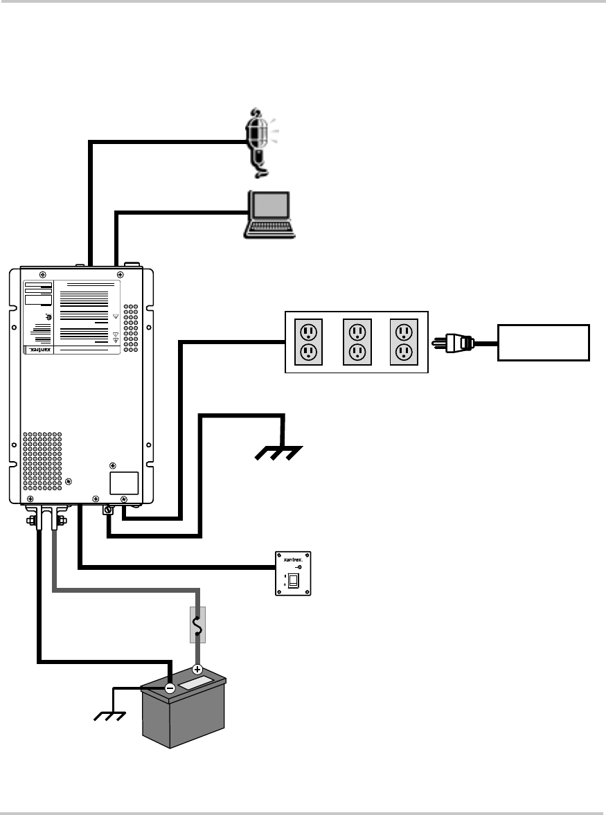
Introduction
The system diagram shown in Figure 2-1 is the basic installation. Review
this diagram carefully before installing the TS400.
Figure 2-1
System Diagram
AC OUTLETS
AC HARDWIRING
GFCI OUTLET
BATTERY (S)
INVERTER
DC FUSE AND DISCONNECT
OR
DC CIRCUIT BREAKER
GFCI OUTLET
TS400 Configuration
Inverter ON
S400 REMOTE
SWITCH
(OPTIONAL)
ADDITIONAL
LOADS
Preparing for Installation
975-0055-01-01 2–3
Preparing for Installation
Read this entire installation chapter so you can plan the installation from
beginning to end. Prior to beginning your installation, review the
“Important Safety Instructions” on page vii.
Installation Codes
It is the installer’s responsibility to determine which codes apply and to
ensure that all applicable installation requirements are met.
Applicable installation codes vary depending on the specific location and
application of the installation. Some examples are:
•The U.S. National Electrical Code (NEC)
•The Canadian Electrical Code (CEC)
•Canadian Standards Association (CSA), and RV Industry Association
(RVIA) requirements for installation in RVs.
WARNING: Electrical shock and fire hazards
Xantrex recommends all wiring be done by qualified personnel.
Disconnect all power sources to prevent accidental shock.
Disable and secure all disconnect devices and automatic
generator starting devices.
It is the installer’s responsibility to ensure compliance with all
applicable installation codes and regulations.
WARNING: Fire hazard
To meet regulatory requirements, the TS400 must be mounted
on a flat horizontal surface with the front panel in the upright
position.
WARNING: Restrictions on use
The TS400 Sine Wave Inverter shall not be used in
connection with life support systems or other medical
equipment or devices.

Installation
2–4975-0055-01-01
Materials List
Your TS400 Sine Wave Inverter package includes:
•One TS400 Sine Wave Inverter
•TS400 Sine Wave Inverter Owner’s Guide
After you unpack your TS400, be sure to record the product information
in the form “Information About Your System” on page WA–4.
If any of these materials are missing or unsatisfactory, please contact
Customer Service.
Installation Tools and Materials
You will need the following tools and materials to install the TS400 and
the optional S400 Remote Switch:
Tools
To install the TS400, you need:
❐Phillips screwdriver: #2
❐Slot screwdrivers: 1/8 inch and 1/4 inch
❐Wrench for DC terminals: 10 mm or adjustable
❐Wire stripper
To install the optional S400 Remote Switch, you need:
❐Power drill with 1/8-inch bit
❐Jigsaw (optional)
❐Feed wire (optional)
Materials for TS400 and Optional S400 Remote Switch
To install the TS400 and optional S400 Remote Switch, you require:
❐DC cables (See Table 2-1 on page 2–9.)
Telephone 1-800-670-0707 (toll free in North America)
1-604-422-2777 (direct)
Fax 1-604-420-2145
Email CustomerService@xantrex.com
Web www.xantrex.com

Preparing for Installation
975-0055-01-01 2–5
❐Appropriately sized connectors. Two DC connectors suitable for ¼
inch (6 mm) that go on the DC input cable terminals. The other cable
connectors will depend on your installation.
❐Crimping tool for fastening lugs and terminals on DC cables (You
may find it more convenient to have the crimp connectors attached by
the company that sells you the cable.)
❐DC fuse and Disconnect or DC circuit breaker (See page 2–9.)
❐Four #10 hardware fasteners to mount the TS400
❐Four #6 self-tapping screws to mount the S400 Remote Switch
Materials for AC output hardwiring
❐Cable requirements:
•within the range of No. 14 to No. 18 AWG (minimum size)
•3 conductors
•solid or stranded
❐1/2 inch cable clamp

Installation
2–6975-0055-01-01
Installing the TS400
Overview
This chapter provides detailed information on installing the TS400. The
overall procedure is divided into 11 steps:
1. Designing your installation (page 2–6)
2. Mounting your inverter (page 2–10)
3. Connecting the chassis ground (page 2–11)
4. Installing the optional S400 Remote Switch
(page 2–12)
5. Getting ready to connect the DC cables (page 2–14)
6. Routing the DC cables (page 2–15)
7. Connecting the DC cables (page 2–16)
8. Connecting your equipment to the GFCI outlets (page 2–18)
9. Hardwiring the AC output (page 2–19)
10. Performing checks prior to initial start-up (page 2–22)
11. Testing your installation (page 2–22)
Step 1: Designing Your Installation
Before doing anything else, you need to determine how you are going to
use your TS400, and then design a power system that will give you
maximum performance. The more thorough your planning, the better
your power needs will be met. In particular, you will need to:
•Be aware of installation codes
•Choose an appropriate location
•Calculate your battery requirements and appropriate battery size
•Calculate the DC cable size
•Select the correct DC fuse and Disconnect or the DC circuit breaker
Installation Codes
See “Installation Codes” on page 2–3 for more information.
Installing the TS400
975-0055-01-01 2–7
Choosing a Location
The inverter should only be installed in a location that meets the
following requirements:
:
WARNING: Risk of fire or explosion
This equipment contains components that could produce arcs or
sparks. To reduce the risk of fire or explosion, do not install this
equipment in compartments containing batteries or flammable
materials, or in locations that require ignition-protected
equipment. This includes any space containing gasoline-
powered machinery, fuel tanks, or joints, fittings, or other
connections between components of the fuel system.
WARNING: Fire hazard
Do not cover or obstruct the ventilation openings. Do not install
this equipment in a compartment with limited airflow.
Overheating may result.
Dry Choose a dry location. Do not allow water or other fluids
to drip or splash on the inverter. Do not expose to rain,
snow or splashing water.
Cool Normal air temperature should be between 32 °F (0 °C)
and 104 °F (40 °C) — the cooler the better within this
range.
Ventilated The inverter requires air circulation to maintain optimum
operating temperature and provide best performance. If the
unit has inadequate ventilation, it may shut down due to
overheating. Allow as much space around the ventilation
openings as possible. Xantrex recommends that other
objects be at least 3 inches (76 mm) away from the
ventilation openings for best performance. The air vented
through the openings should also have a path to circulate
away from the inverter.
Safe Do not install the inverter in the same compartment as
batteries or in any compartment containing flammable
liquids like gasoline.
Installation
2–8975-0055-01-01
Battery Requirements
The batteries that you use strongly affect the performance of the TS400. It
is important to connect the inverter to the correct size and type of battery.
See Appendix B, “Battery Types and Sizes” on page B–1 for more
information.
Close to
battery
compartment
Long DC cables must be very large (and expensive), so
they should be kept short (see Table 2-1 on page 2–9).
However, the unit should NOT be installed in the battery
compartment due to the possible presence of explosive
hydrogen gas from the batteries.
Protected
from battery
acid and
gases
Never allow battery acid to drip on the inverter or its
wiring when filling the batteries or reading their specific
gravity. Do not mount the unit where it will be exposed to
gases produced by the batteries. These gases are corrosive
and prolonged exposure will damage the inverter.
Orientation To meet regulatory requirements, the TS400 must be
mounted on a flat horizontal surface with the front panel in
the upright position.
CAUTION
The TS400 Sine Wave Inverter must only be connected to
batteries with a nominal output voltage of 12 volts. The TS400
Sine Wave Inverter will not operate from a 6 volt battery and
will be damaged if connected to a 24 volt battery.

Installing the TS400
975-0055-01-01 2–9
DC Cables
For the best load starting performance, the DC cables should be as short
and large as possible. See Table 2-1 for minimum recommended cable
size. Using a smaller cable may cause the inverter to shut down under
heavy load. A larger cable may be used.
DC Fuse and Disconnect or DC Circuit Breaker
If you are using a DC fuse and Disconnect, a maximum 80 amp Class T
fuse shall be used for the DC fuse. A fuse of lower rating can be used, but
it shall not be lower than 60 amp Class T. The Disconnect shall be rated at
least 50 amps.
Additionally, a DC circuit breaker rated 50 amps can be used.
Table 2-1
Minimum Recommended DC Input Cable (copper) — AWG
&DEOH/HQJWK%DWWHU\WR,QYHUWHU
HDFKFDEOH
0LQLPXP5HFRPPHQGHG
&DEOH6L]H³$:*
0–10 feet (0–3 meters) No. 6
10–15 feet (3–4.5 meters) No. 4
15–30 feet (4.5–9 meters) No. 2
30–40 feet (9–12 meters) No. 0
Installation
2–10 975-0055-01-01
Step 2: Mounting Your Inverter
Mount your inverter before you connect any wires or cables.
For your convenience, the inverter dimensions are provided in
Figure 2-9 on page 2–23.
To mount your TS400:
1. Turn the On/Standby switch on the front panel of the inverter to
Standby ( ) position.
2. Select an appropriate mounting location and orientation.
See “Choosing a Location” on page 2–7.
3. Hold the inverter against the mounting surface, mark the position of
the mounting screws, and then remove the inverter.
OR
Use “Inverter Dimensions” on page 2–23 to mark the position of the
mounting screws.
You can also download a full-scale version of the mounting template
from www.xantrex.com
4. Pilot drill the four mounting holes.
5. Fasten the inverter to the mounting surface with four #10 hardware
fasteners.
WARNING: Fire hazard
To meet regulatory requirements, the TS400 must be mounted
on a flat horizontal surface with the front panel in the upright
position.
Installing the TS400
975-0055-01-01 2–11
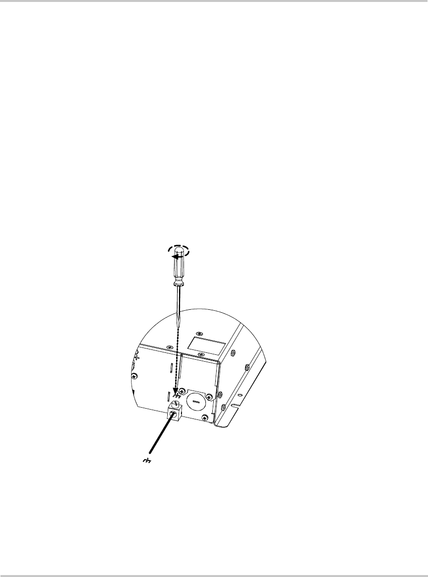
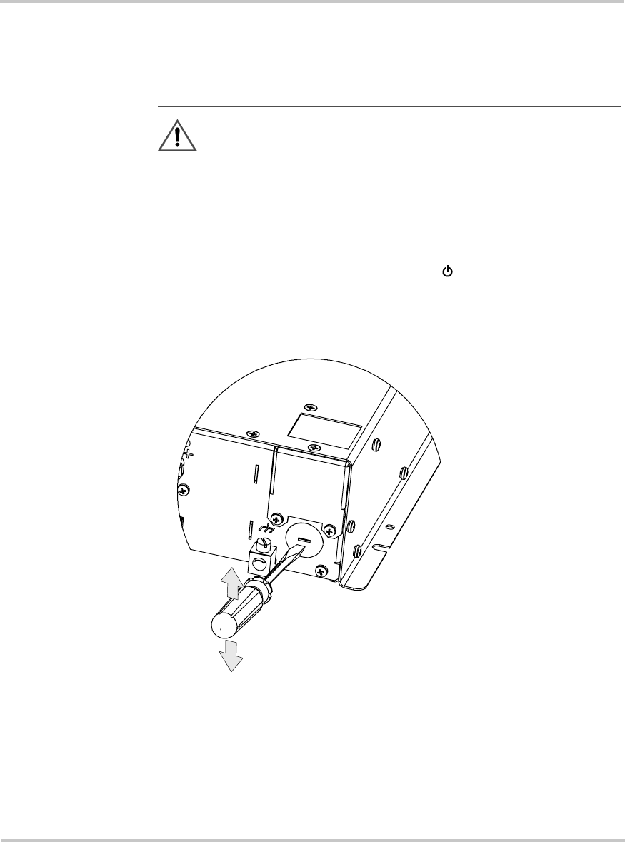
Step 3: Connecting the Chassis Ground
The chassis ground lug is used to connect the chassis of the inverter to
your system’s chassis grounding point, as required by installation codes.
Use copper cable that is either bare or provided with green insulation. Do
not use the chassis ground lug for your AC output grounding wire.
To connect the chassis ground:
Refer to Figure 2-2.
1. Using the 1/4 inch slot screwdriver, loosen the screw on the chassis
ground lug.
2. Connect a No. 8 AWG copper cable between the inverter’s chassis
ground lug and the DC grounding point for your system.
In an RV or vehicle installation, this will usually be the vehicle
chassis or a dedicated chassis ground bus.
3. Tighten the screw to a torque of 6–7 lbf-in (0.68–0.79 Nm).
Figure 2-2
Connecting the Chassis Ground
Installation
2–12 975-0055-01-01
Step 4: Installing the Optional S400 Remote Switch
Installing the S400 Remote Switch (Xantrex product number 808-2400) is
optional. The TS400 operates normally without the remote switch.
The S400 Remote Switch is designed to be flush mounted on a wall,
bulkhead or panel. A 25 foot (7.5 meter) telephone cable is supplied with
the remote switch.
If you want to extend the cable, use a high quality, 4-wire telephone
extension cable with 6-position, 4-contact connectors. The maximum
recommended cable length is 50 feet (15 meters).
For your convenience, a full-scale mounting template is provided on
page 2–24.
To install the remote switch:
1. Choose a location that is dry, free from corrosive or explosive fumes,
and otherwise appropriate for installing an electronic device.
2. Using the template, pilot-drill the mounting holes. Cut an opening
about 2 inches x 1.2 inches (50 mm x 30 mm) and 1.4 inches (35 mm)
deep.
3. Route the telephone cable inside the wall and through the opening to
the inverter.
WARNING: Shock hazard
Before making an opening in a wall, bulkhead or panel, ensure
there is no wiring or other obstruction within the wall.
WARNING: Shock hazard
Ensure both the S400 Remote Switch and the TS400 are in
Standby ( ) mode before installing.
Note: The S400 Remote Switch connects to a jack at the back of the
inverter. See “System Diagram” on page 2–2.
Installing the TS400
975-0055-01-01 2–13
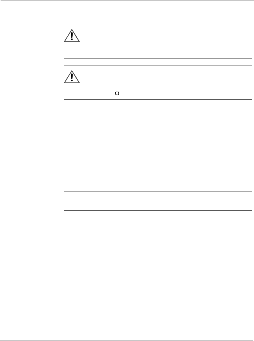
4. Connect one end of the telephone cable to the back of the inverter as
shown in Figure 2-3.
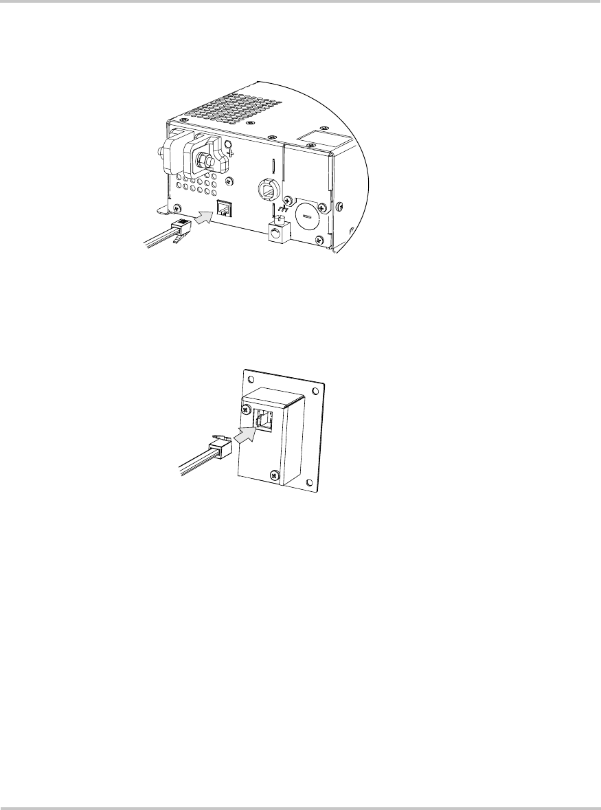
5. Connect the other end of the telephone cable to the remote switch as
shown in Figure 2-4.
6. Place the remote switch in the opening and secure it with the four #6
fasteners.
Figure 2-3
Connecting Cable to the TS400
Figure 2-4
Connecting Cable to the S400 Remote Switch

Installation
2–14 975-0055-01-01
Step 5: Getting Ready to Connect the DC Cables
The DC cables should be as short as possible and large enough to handle
the required current, in accordance with the electrical codes or regulations
applicable to your installation. The minimum recommended DC cable
size is specified in Table 2-1 on page 2–9. For the recommended DC fuse
and Disconnect or DC circuit breaker, see page 2–9.
To prepare the DC cables:
Refer to Figure 2-5, “Connection Order for DC Cables” on page 2–16.
1. Cut the negative cable to the recommended length. (See Table 2-1 on
page 2–9 for DC cable size.) Strip off enough insulation so you can
install the terminal you will be using.
Xantrex recommends the use of crimp connectors such as a ring lug
type. The connector should be designed for a 6 mm or 1/4 inch stud
size to connect to the TS400 Sine Wave Inverter. If a crimp connector
is used, it should be crimped using the tool indicated by the connector
manufacturer.
2. Cut two lengths of positive cable. One cable (maximum 18 inches)
goes from the battery to the DC fuse and Disconnect or to the DC
circuit breaker. The other cable goes from the DC fuse and
Disconnect or to the DC circuit breaker to the positive DC terminal.
3. Attach the connectors to the ends of both cables. Make sure no stray
wire strands protrude from the terminals.

Installing the TS400
975-0055-01-01 2–15
Step 6: Routing the DC Cables
Guidelines for Routing the DC Cables
•Do not attempt to use the chassis in place of the battery negative
connection for grounding. The inverter requires a reliable return path
directly to the battery.
•To reduce the chance of interference, keep the positive and negative
cables close together—ideally, tied together at regular intervals as
shown in Figure 2-5, “Connection Order for DC Cables” on page 2–
16.
•To ensure maximum performance from the inverter, do not route your
DC cables through a DC distribution panel, battery isolator, or other
device that will cause additional voltage drops. The exception is the
DC fuse and Disconnect or the DC circuit breaker which is required
to protect the DC wiring.
WARNING: Fire and shock hazard
Route the cables away from sharp edges which might damage
the insulation. Avoid sharp bends in the cable.
Installation
2–16 975-0055-01-01
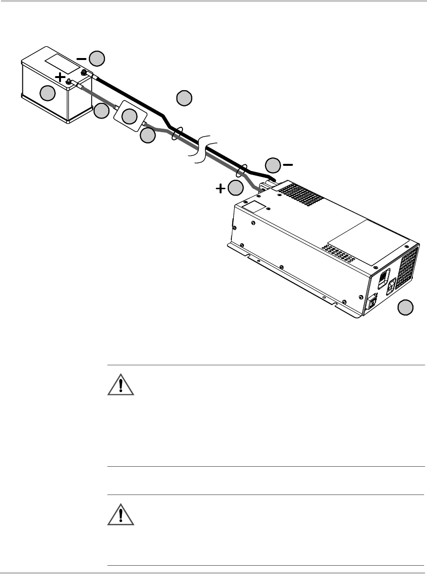
Step 7: Connecting the DC Cables
Figure 2-5
Connection Order for DC Cables
CAUTION: Reverse polarity
Before making the final DC connection, check cable polarity at
both the battery and the inverter. Positive (+) must be connected
to positive (+); negative (–) must be connected to negative (–).
Reversing the positive (+) and negative (–) battery cables will
damage the inverter and void your warranty.
WARNING: Fire hazard
Use only appropriately sized copper cable. Make sure all DC
connections are tightened to a torque of 2.2–2.6 lbf-ft
(3.0–3.5 Nm). Loose connections will overheat.
7
8
5
4
Inverter
Battery 3
2
1
6
9

Installing the TS400
975-0055-01-01 2–17
To connect the DC cables:
Connect the DC cables as shown in Figure 2-5, in the order shown by the
numbers.
1. Switch the On/Standby switch to the Standby ( ) position.
2. Route the DC cables from the battery bank to the inverter.
See “Step 6: Routing the DC Cables” on page 2–15.
3. Install a DC fuse and Disconnect or a DC circuit breaker in the
positive side of the circuit within 18 inches of the battery.
This protects your battery and wiring in case of accidental shorting.
(See “DC Fuse and Disconnect or DC Circuit Breaker” on page 2–9
for recommended fuse size and type.) Open the DC fuse and
Disconnect or turn off the DC circuit breaker.
4. Connect one connector on the POSITIVE (+) cable to the POSITIVE
DC terminal on the inverter. Tighten the nut to a torque of
2.2–2.6 lbf-ft (3.0–3.5 Nm).
5. Connect the other connector to the positive (+) terminal DC fuse and
Disconnect or to the DC circuit breaker. Use a wrench to tighten the
connection according to the manufacturer’s recommendations. Test
that the cable is secure.
6. Attach a short DC cable from the unconnected end of the DC fuse and
Disconnect or DC circuit breaker. Tighten appropriately.
7. Observing polarity carefully, connect the other end of the fused cable
to the POSITIVE (+) terminal of the battery. Tighten this connection
to the battery manufacturer’s recommended torque.
8. Connect one connector on the NEGATIVE (–) cable to the
NEGATIVE (–) battery terminal. Tighten the connection according to
the battery manufacturer’s recommended torque.
9. Check that the polarity of the DC connections is correct: positive (+)
on the inverter is connected to the positive (+) on the battery, and
negative (–) is connected to the negative (–).
10. Connect the other connector of the NEGATIVE (–) cable onto the
NEGATIVE (–) terminal on the TS400 Sine Wave Inverter.
11. Use a wrench to tighten the nut to a torque of 2.2–2.6 lbf-ft
(3.0–3.5 Nm). Test that the cable is secure.

Installation
2–18 975-0055-01-01
Step 8: Connecting Your Equipment to the GFCI Outlets
To connect your AC equipment to the GFCI outlets:
1. Turn the inverter’s On/Standby switch to Standby ( ).
2. Turn your AC equipment off.
3. Connect your AC equipment to the GFCI outlets in the front panel.
4. If you wish to connect more equipment, use a multiple-outlet
extension cord. Ensure that the total power drawn does not exceed
400 watts.
Note: Ensure that the Reset button on the GFCI outlets is not tripped.
Important:
If you have more permanent loads to connect to the
inverter, Xantrex recommends that they be hardwired. See “Step 9:
Hardwiring the AC Output” on page 2–19.
Installing the TS400
975-0055-01-01 2–19
Step 9: Hardwiring the AC Output
If you wish to permanently connect additional AC outlets, Xantrex
recommends hardwiring the AC output connections.
To hardwire the AC output connections:
1. Turn the On/Standby switch to Standby ( ).
2. Remove the knockout using a slot screwdriver as shown in
Figure 2-6. Do not leave the knockout inside the wiring box.
WARNING: Fire, shock, and energy hazards
Make sure wiring is disconnected from all electrical sources
before handling. All wiring must be done in accordance with
local and national electrical wiring codes. Do not connect the
output leads of the inverter to any incoming AC source.
Figure 2-6
Removing the Knockout
Installation
2–20 975-0055-01-01
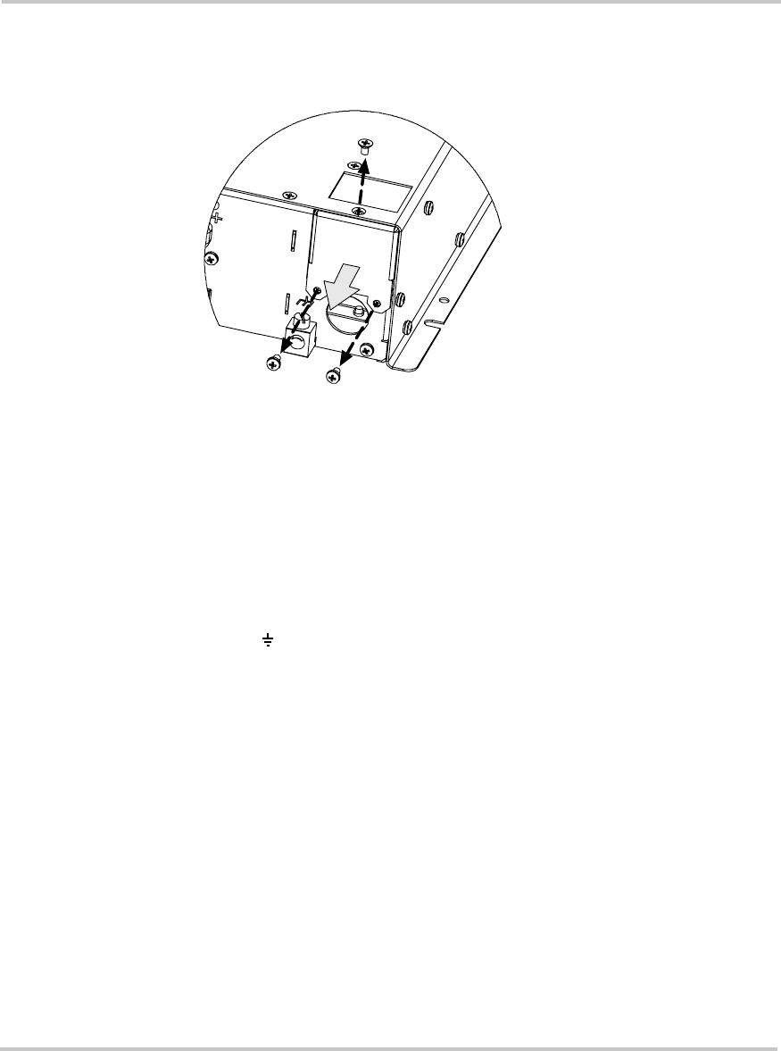
3. Locate the wiring box access panel, and remove the three screws to
access the wiring box as shown in Figure 2-7.
4. Remove the wiring box access panel from the unit.
5. Install a 1/2 inch cable clamp.
6. Locate the terminal block.
The three terminals are labelled as follows:
•L Line
•N Neutral
• Ground
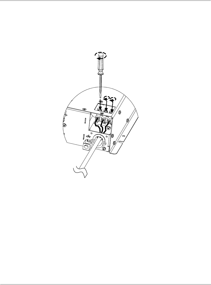
7. Strip about 2 inches (50 mm) off the jacket of the AC output cable.
The AC output cable must be either solid or stranded, within the
range of No. 14 to No. 18 AWG, and have three conductors.
8. Strip approximately 3/8 inch (10 mm) off the insulation of the cable.
9. Run the AC cable through the cable clamp and into the wiring box.
10. Using the 1/8 inch slot screwdriver, loosen the wire attachment
screws on the terminals by five turns.
11. Insert and fasten the Ground wire into the corresponding terminal.
12. Insert the Line and Neutral wires into the corresponding terminals.
Figure 2-7
Removing the 3 Screws on the Wiring Box Access Panel
Installing the TS400
975-0055-01-01 2–21
13. Tighten the wire attachment screws to a torque of 1.3–1.8 lbf-ft
(1.76–2.44 Nm) as shown in Figure 2-8. Leave some slack inside the
output wiring box.
14. Secure the cable clamp on the cable jacket.
15. Attach the wiring box access panel and tighten the three screws.
Figure 2-8
Completing the Hardwiring
Installation
2–22 975-0055-01-01
Step 10: Performing Checks Prior to Initial Start-up
Before starting up your inverter, ensure these conditions are met:
❐Chassis ground is properly installed
❐On/Standby switch is in the Standby ( ) position on the TS400
❐Positive (+) battery cable is connected to the positive (+) battery
terminal through the DC fuse and Disconnect or DC circuit breaker
❐Negative (–) battery cable is connected to the negative (–) battery
terminal
❐Battery voltage is within the proper range for this unit
(10.3–15.3 volts DC)
❐DC Fuse is intact (not blown)
Step 11: Testing Your Installation
When you are ready to test your installation and operate the TS400, close
the DC fuse and Disconnect or the DC circuit breaker to supply DC power
to the TS400.
To test the TS400:
1. Turn the inverter’s On/Standby switch to the On ( ) position. If the
optional S400 Remote Switch is installed, turn the On/Standby switch
on the remote switch to the On ( ) position.
The green Inverter ON indicator illuminates.
2. Plug an appliance of 400 watts or less into one of the GFCI outlets.
3. Turn the appliance on to verify that it operates.
4. If the appliance operates, your installation is successful.
5. If the red Fault light illuminates, see “Troubleshooting” on page 4–1.
WARNING: Shock hazard
The On/Standby switch on the TS400 does not disconnect DC
power to the TS400.
Installing the TS400
975-0055-01-01 2–23
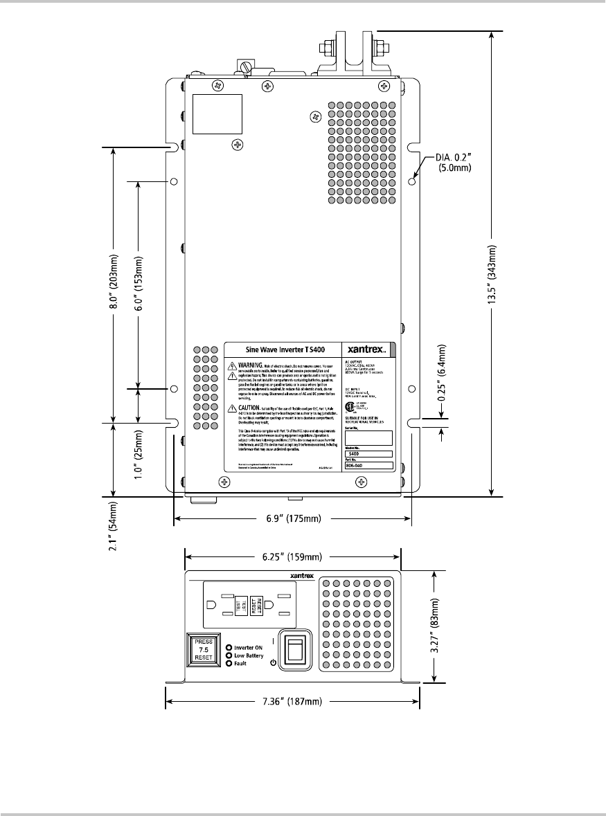
Figure 2-9
Inverter Dimensions
This drawing is not to scale. A full-scale mounting template is available at www.xantrex.com
T
5
Installation
2–24 975-0055-01-01
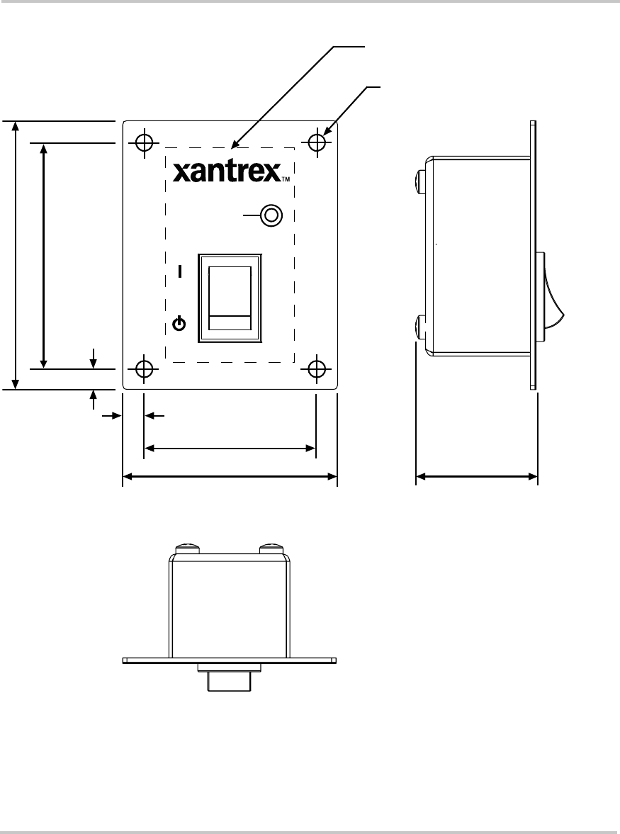
Figure 2-10
S400 Remote Switch Mounting Template (Scale approximately 1:1)
2.5" (63.5)
2" (50.8)
Inverter ON
2.1" (53.5)
1.6" (40.8)
0.2" TYP (5.0)
0.2" TYP (5.0)
1.1" (28.3)
DRILL Ø0.125 (1/8") HOLE
4 PLACES FOR #6/32 SELF
TAPPING SCREW
CUTOUT PANEL 2" X 1.2" (50.8 X 30.5)
(DASHED LINE)
Operation
Chapter 3, “Operation” explains how to use your TS400
effectively. This chapter explains how to turn the TS400 to
On () or Standby ( ) from the front panel or from the optional
S400 Remote Switch, monitor the status of the TS400, and
reset the inverter.
CAUTION
Read this chapter before operating the TS400 Sine Wave
Inverter.
WARNING: Restrictions on use
The TS400 Sine Wave Inverter shall not be used in connection
with life support systems or other medical equipment or
devices.
Operation
3–2975-0055-01-01
Front Panel Features
Before you begin to operate the TS400, review the front panel features in
Figure 3-1.
For a detailed description of each of the different features, see “Front
Panel of the TS400” on page 1–4 in the “Introduction” chapter.
\
Figure 3-1
Front Panel of the TS400
Table 3-1
Front Panel Features
)HDWXUH 'HVFULSWLRQ
1 On/Standby Switch
2 Inverter ON light
3 Low Battery light
4 Fault light
5 Supplemental Circuit Protection button
6 Two GFCI outlets
7 Ventilation openings
21
3
54
6
7
Operating the TS400
975-0055-01-01 3–3
Operating the TS400
On/Standby switch You can turn the TS400 to On () or to Standby ( ) using the On/Standby
switch (see “Front Panel of the TS400” on page 3–2).
Optional remote
switch If you have installed the optional S400 Remote Switch, you can also use
the remote switch to turn the TS400 to On () or to Standby ( ). See
“Using the Optional S400 Remote Switch” on page 3–4.
Resetting the TS400 The On/Standby switch on the TS400 or the S400 Remote Switch is also
used to reset the TS400 after a Fault condition. See “Resetting After a
Fault or Shutdown” on page 3–7.
Turning the TS400 On
When the On/Standby switch is turned to On (), the TS400 powers your
equipment using energy from the battery.
To turn the TS400 on:
1. Turn the On/Standby switch on the TS400 to the On () position.
The Inverter ON light illuminates on the TS400.
AND
If you have installed the S400 Remote Switch, turn the S400 Remote
Switch to On ().
2. Operate your equipment.
Turning the TS400 to Standby When Not in Use
When you are not using the TS400 and want to conserve battery power,
turn the inverter’s On/Standby switch to the Standby ( ) position.
To turn the TS400 to standby:
1. Turn your equipment off.
2. Turn the On/Standby switch on the TS400 or the optional S400
Remote Switch to the Standby ( ) position.
The Inverter ON light turns off.
With the On/Standby switch in Standby ( ) position, the TS400 draws no
current from the battery.
WARNING: Shock hazard
The TS400 has On mode and Standby mode only. It does not
have an Off mode, that is, DC power is permanently connected
to the unit.
Operation
3–4975-0055-01-01
If the On/Standby switch on the TS400 is in the On () position and the
optional S400 Remote Switch is in the Standby ( ) position (see
“Important” on page 3–4), the TS400 draws very little current (about
1 mA) from the battery.
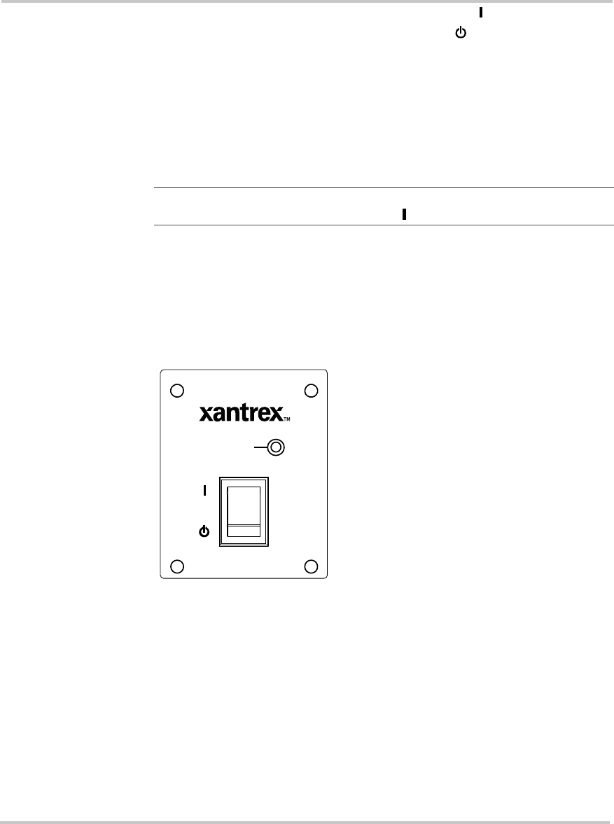
Using the Optional S400 Remote Switch
The S400 Remote Switch performs the same function as the On/Standby
switch on the TS400.
Purpose The S400 Remote Switch provides On/Standby control of the TS400 from
a convenient location of up to 25 feet (7.5 meters) away using the
supplied telephone cable.
Cable length You can use a longer cable up to a maximum recommended length of 50
feet (15 meters). Xantrex recommends using a high quality 4-wire
telephone cable wth 6-position, 4-contact connectors.
Important: For the Remote Switch to function, the On/Standby switch
on the TS400 must be turned to the On () position.
Figure 3-2
S400 Remote Switch
Inverter ON

Recharging Your Batteries
975-0055-01-01 3–5
Recharging Your Batteries
Low Battery light If the Low Battery light illuminates on the TS400 and you hear the low
battery alarm, your battery level is low (less than 10.7 volts). As long as
the Inverter ON light is illuminated on the TS400, the unit will continue
to supply inverter power to your equipment.
However, Xantrex highly recommends that you recharge your battery.
Turn off your equipment and recharge your battery. When the Low
Battery light and the audible alarm turn off (at 12.6 volts), you can restart
your equipment. See “Restarting or Operating Multiple Pieces of
Equipment”.
Importance of
recharging Xantrex recommends that you recharge your batteries before they are
50% discharged. This gives them a much longer life cycle than recharging
them when they are almost completely discharged. See “Battery State of
Charge” on page B–8.
More information For more information about battery chargers and battery monitors, see the
Xantrex web site at www.xantrex.com.
Recovering from Low Battery Voltage Shutdown
If the Low Battery light illuminates, you hear an alarm, and the Inverter
ON light on the front panel turns off when you are operating the unit, the
TS400 has shut down due to low battery voltage (10.3 volts). Output
power is interrupted.
To recover from a low battery voltage shutdown:
1. Turn off your equipment and recharge your battery. The alarm will
turn off when battery voltage reaches 11.6 volts.
2. When the Low Battery light turns off (12.6 volts) and the Inverter ON
light illuminates, you can restart your equipment.
Restarting or Operating Multiple Pieces of Equipment
The TS400 can handle several pieces of equipment simultaneously as
long as they do not draw more than 400 watts in total.
To restart or operate several pieces of equipment:
◆Turn each device on separately after the TS400 has started.
This action ensures that the TS400 does not have to deliver the
starting current for all the loads at once and will help to prevent an
overload shutdown.

Operation
3–6975-0055-01-01
Monitoring the Operating Status
The operating status of the TS400 is indicated by three lights on the front
panel and an audible alarm. See Table 3-2.
For an illustration of the indicator lights on the front panel, see “Front
Panel of the TS400” on page 3–2.
If none of the front panel lights are on, see “Troubleshooting Reference”
on page 4–2.
Table 3-2
Status of Indicator Lights and Alarm
/LJKW &RORU 6WDWXV $FWLRQ
Inverter ON Green When the TS400 is on, the Inverter
ON light illuminates. You can run your equipment using
energy from the battery.
Low Battery &
Inverter ON
(with audible
alarm)
Yellow &
Green When the Low Battery and
Inverter ON lights illuminate, your
battery level is low. (The battery
voltage has dropped below 10.7
volts DC.)
You can run your equipment but your
battery level is low. Charge your
battery.
Low Battery
(with audible
alarm)
Yellow When only the Low Battery light
illuminates, your battery level is
critically low. (The battery voltage
has dropped below 10.3 volts DC.)
You cannot run equipment. Charge
your battery.
Fault Red The Fault light illuminates
whenever there is a battery over-
voltage fault condition (exceeds
15.3 volts), output overload fault
condition or over-temperature
fault condition.
You cannot run equipment as the AC
output is disabled. Clear the fault
condition. Reset the TS400 by
turning the On/Standby switch to
Standby () and then to On ( ).

Resetting After a Fault or Shutdown
975-0055-01-01 3–7
Resetting After a Fault or Shutdown
This section provides explanations and procedures for resetting the TS400
after a fault or shutdown.
If you are unable to resolve the problem after referring to Table 3-3, refer
to the “Troubleshooting” section on page 4–2.
Table 3-3
Resetting After a Fault or Shutdown
)DXOW 6WDWXV $FWLRQ
Shutdown The TS400 needs to be reset. Turn the On/Standby switch on either the
inverter’s front panel or the optional S400
Remote Switch to Standby ( ) and then to
On ( ).
Short Circuit If there is a short circuit, the
Supplemental Circuit
Protection button trips.
Remove the short circuit condition then press
the Supplemental Circuit Protection button.
Ground Fault When a fault condition is
detected, the Reset button on
the GFCI outlet trips and
power to the appliance is
interrupted.
Reset: To resume normal operation, determine
and correct the ground fault, then press the
Reset button.
Test: Press the Test button on the GFCI outlet
with the TS400 turned to On ( ). The Reset
button should trip. Press the Reset button to
reset the GFCI and continue with normal
operation. This test should be performed on a
monthly basis.
If the Reset button does not trip, the GFCI may
have failed. Contact your dealer to have a
qualified service person examine the TS400.
Overload The TS400 is designed to
provide 400 watts continuously
and 800 watts surge capability
for five seconds. If the
connected equipment draws
more than the rated power, the
TS400 will shut down and the
red Fault light illuminates.
Disconnect the equipment connected to the
inverter and then turn the On/Standby switch
on either the inverter’s front panel or the S400
Remote Switch to Standby ( ) and then to
On ( ).
See also “Recharging Your Batteries” on
page 3–5.
3–8

Troubleshooting
The TS400 is designed for high reliability and has a number of
protection features for trouble-free operation. If, however, you
have any problems operating your inverter, refer to the
“Troubleshooting Reference” on page 4–3.
Read this troubleshooting chapter before calling your dealer or
Xantrex Customer Service. See page ii for contact
information.
If you cannot resolve the problem, record the information
asked for on the form, “Information About Your System” on
page WA–4. Providing this information to our Customer
Service Representatives will help them to assist you better.
Troubleshooting
4–2975-0055-01-01
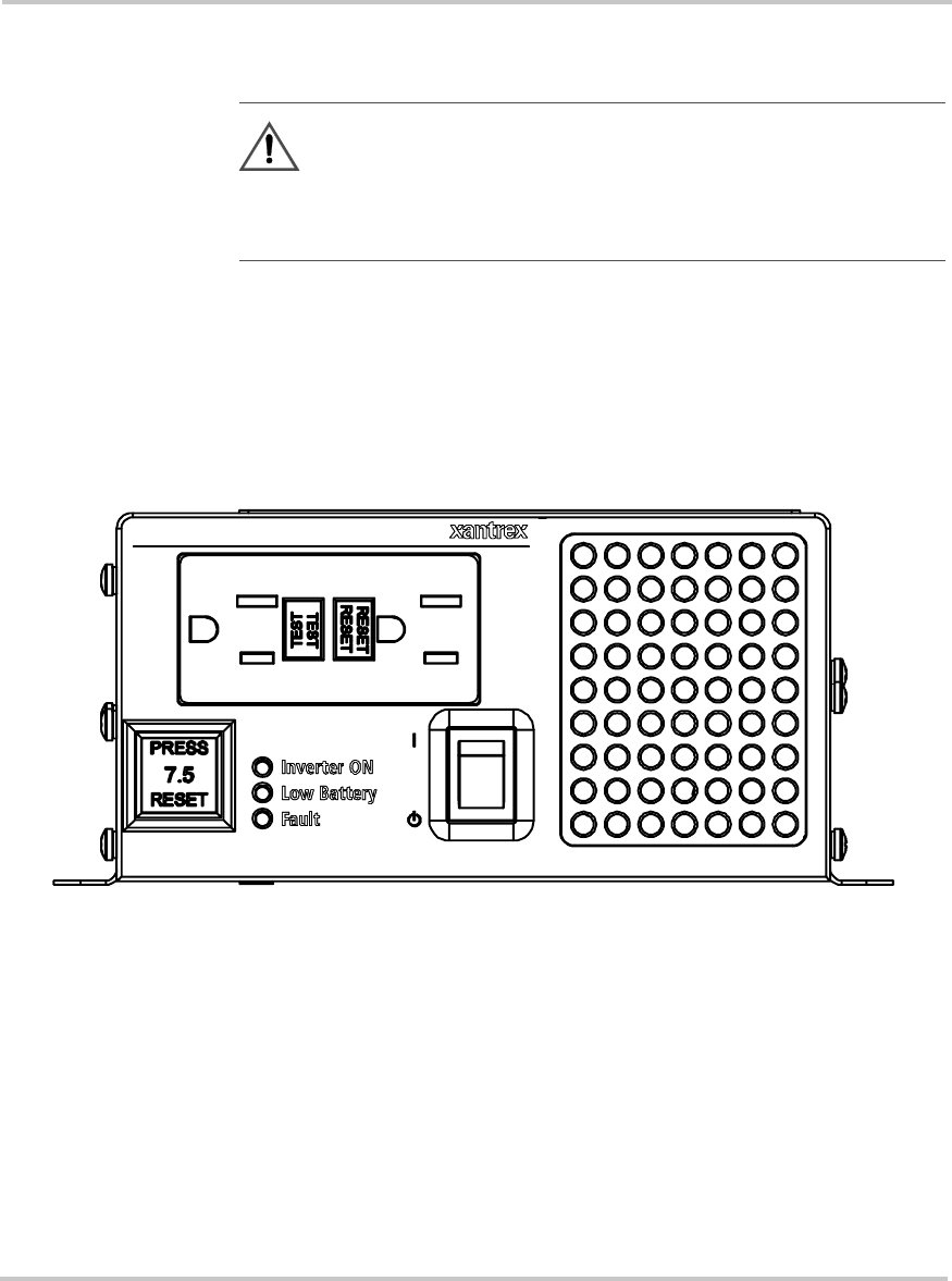
Troubleshooting Reference
This section provides you with troubleshooting tips to identify and solve
most problems that can occur with the TS400.
Before contacting your dealer or customer service, please refer to the
table, “Troubleshooting Reference”.
If the “Troubleshooting Reference” table does not help you resolve the
problem, contact your dealer or Xantrex customer service.
For a detailed description of the different features, see “TS400 Features”
on page 1–4.
WARNING: Electrical shock and fire hazard
Do not disassemble the TS400. It does not contain any user-
serviceable parts. Attempting to service the unit yourself could
result in electrical shock or fire.
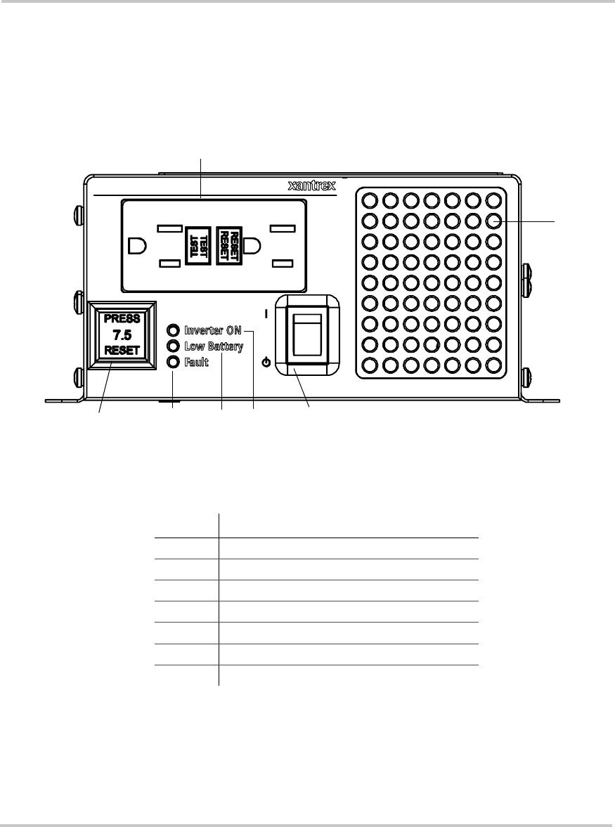
Figure 4-1
Front Panel

Troubleshooting Reference
975-0055-01-01 4–3
Table 4-1
Troubleshooting Reference
3UREOHP 3RVVLEOH&DXVH 6ROXWLRQ
No output voltage. No
indicator lights are
illuminated.
The switch is in Standby ( )
mode.
No input power to the
inverter.
DC fuse open (external)
Turn the On/Standby switch on the inverter
to On ( ).
Check the DC wiring to the inverter for
loose connections, frayed wiring or an open
DC Disconnect.
Have a qualified service technician check
and replace the fuse.
No output voltage. Inverter
ON light is illuminated. Supplemental Circuit
Protection button has tripped.
GFCI has tripped.
Disconnect all equipment to reduce the
overload. Check the AC wiring and reset
the Supplemental Circuit Protection button.
Clear the ground fault, and reset the GFCI
by pressing the Reset button on the GFCI.
No output voltage. Fault light
is illuminated. Inverter may be overloaded.
Battery voltage may be too
high.
Over temperature.
Disconnect all equipment connected to the
inverter, and reset the inverter by turning
the On/Standby switch to Standby () and
then to On ( ).
The inverter will restart if the battery
voltage drops below 14.5 volts DC.
Allow the inverter to cool down. The
inverter will restart automatically.
No output voltage. Low
Battery light is illuminated
and alarm is on.
Battery voltage is too low.
Poor DC wiring.
Recharge the battery to more than 12.6
volts DC. The inverter will restart
automatically.
Turn the inverter to Standby ().
Disconnect the DC wiring. Use proper
wiring and ensure all connections are tight.

Troubleshooting
4–4975-0055-01-01
Output voltage is present.
Inverter ON light and Low
Battery light are illuminated
and alarm is on.
Battery voltage is low. Disconnect all equipment. Charge the
batteries.
Fan does not turn on. The internal components of
the inverter are not warm. No action. The fan will run automatically
when necessary to cool the internal
components of the inverter.
Fan runs all the time. The amount of power being
consumed by the equipment
is high.
The ambient temperature is
high.
No action. The fan will run at lower speeds
and stop automatically when the internal
temperature of the inverter falls.
No action. The fan will run at lower speeds
and stop automatically when the ambient
temperature falls.
For more information on the “Fan Cooling
System”, refer to page A–3.
Table 4-1
Troubleshooting Reference
3UREOHP 3RVVLEOH&DXVH 6ROXWLRQ

Specifications
Appendix A, “Specifications”, contains the electrical and
physical specifications for the TS400.
All specifications are subject to change without notice.
Specifications
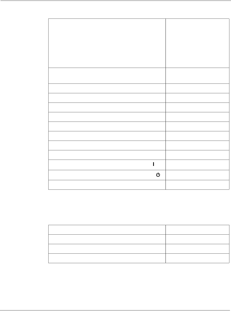
A–2975-0055-01-01
Electrical Specifications
Physical Specifications with Projections
Output power at 12 VDC input
•Continuous
•Surge capacity for 5 seconds
400 VA1, 32 °F to 104 °F
(0 °C to 40 °C), derated
linearly to 300 VA at
122 °F (50 °C)
800 VA
1.The term “watts” has been used throughout the guide to refer to output
power. More correctly, the actual unit of power used is “VA”.
Input voltage 12 VDC nominal
10.3 to 15.3 VDC
Output voltage 120 VAC RMS ± 3 VAC
Output frequency 60 Hz ± 0.05 Hz
Output wave form Sine wave
Total harmonic distortion of output waveform <3%
High battery shutdown 15.3 ± 0.3 VDC
Low battery indication and audible alarm 10.7 ± 0.3 VDC
Low battery shutdown 10.3 ± 0.3 VDC
Maximum efficiency 88%
No load current draw with switch turned to On ( ) 1.25 ADC Maximum
No load current draw with switch set to Standby ()0 ADC
Supplemental circuit protector 7.5 AAC
Length 13.5 inches (343 mm)
Width 7.36 inches (187 mm)
Height 3.27 inches (83 mm)
Weight 10 lb (4.54 kg)

Regulatory Approvals
975-0055-01-01 A–3
Regulatory Approvals
Fan Cooling System
A fan cools the internal heat-generating components of the inverter. The
fan begins to operate when the internal temperature rises. The speed of the
fan increases with internal temperature.
The fan turns off if the internal temperature of the inverter drops.
CSA/NRTL approved to CSA C22.2 No. 107.1 and UL 458
FCC Class B
A–4

Battery Types and
Sizes
The batteries that you use strongly affect the performance of
the TS400. It is important to connect the inverter to the correct
size and type of battery.
The information in Appendix B will help you to select,
connect, and maintain batteries that are most appropriate for
your application.

Battery Types and Sizes
B–2975-0055-01-01
Battery Types
Automotive Starting Batteries
The lead-acid battery you are most familiar with is probably the starting
battery in your vehicle. An automotive starting battery is designed to
deliver a large amount of current for a short period of time (so it can start
your engine). Only a small portion of the battery’s capacity is used when
starting the engine, and the spent capacity is quickly recharged by the
running engine.
The starting battery in your vehicle is not designed for repeated deep-
discharge cycles where the battery is almost completely discharged and
then recharged. If a starting battery is used in this kind of deep discharge
service, it will wear out very rapidly.
Deep-Cycle Batteries
Deep-cycle batteries are designed for deep discharge service where they
will be repeatedly discharged and recharged. They are marketed for use in
recreational vehicles, boats, and electric golf carts—so you may see them
referred to as RV batteries, marine batteries, or golf cart batteries.
For most applications of the TS400, Xantrex recommends that you use
one or more deep-cycle batteries that are separated from the vehicle’s
starting battery by a battery isolator.
A battery isolator is a solid-state electronic circuit that allows equipment
to be operated from an auxiliary battery without danger of discharging the
vehicle’s starting battery. During vehicle operation, the battery isolator
automatically directs the charge from the alternator to the battery
requiring the charge.
Battery isolators are available at marine and RV dealers and most auto
parts stores.

Battery Size
975-0055-01-01 B–3
Battery Size
Battery size or capacity is as important as the battery type for efficient
operation of your loads. Xantrex recommends that you purchase as much
battery capacity as you need.
A number of different standards are used to rate battery energy storage
capacity. Automotive and marine starting batteries are normally rated in
cranking amps. This is not a relevant rating for continuous loads like an
inverter. Deep-cycle batteries use a more suitable rating system, either
“amp-hours” (“Ah”) or “reserve capacity” in minutes.
Battery Reserve Capacity Battery reserve capacity is a measure of
how long a battery can deliver a certain amount of current—usually 25
amps. For example, a battery with a reserve capacity of 180 minutes can
deliver 25 amps for 180 minutes before it is completely discharged.
Amp-hour (Ah) Capacity Amp-hour capacity is a measure of how
many amps a battery can deliver for a specified length of time—usually
20 hours. For example, a typical marine or RV battery rated for 100 Ah
can deliver 5 amps for 20 hours (5 A x 20 hours = 100 Ah).
This same battery can deliver a higher or lower current for less or more
time, limited approximately by the 100 Ah figure (for example, 50 A for 2
hours, or 200 A for 1/2 hour), but usually the capacity figure given is only
accurate at the specified rate (20 hours).
To calculate the battery capacity you require, read “Estimating Battery
Requirements” on page B–4 and “Battery Sizing Example” on page B–4,
and then complete the “Battery Sizing Worksheet” on page B–5.
CAUTION
The TS400 Sine Wave Inverter must only be connected to
batteries with a nominal output voltage of 12 volts. The TS400
Sine Wave Inverter will not operate from a 6 volt battery and
will be damaged if connected to a 24 volt battery.

Battery Types and Sizes
B–4975-0055-01-01
Estimating Battery Requirements
To determine how much battery capacity you need:
1. Determine how many watts are consumed by each appliance that you
will operate from the TS400. You can normally find the watt rating
labelled on the product. If only the current draw is given, multiply it
by 115 to get the power consumption in watts.
2. Estimate how many hours each appliance will be operating each day.
3. Calculate the daily watt-hours needed for each appliance.
4. Add the total number of watt-hours needed for all the equipment and
multiply it by the number of days between charges.
5. Divide the total watt-hours of AC load between charges by 10. This
gives the battery Ah used between charges.
6. Double the total Ah used between charges to get the recommended
battery size in Ah.
See the battery sizing example that follows.
Battery Sizing Example
This battery sizing example illustrates a typical calculation, assuming an
opportunity to charge the batteries every three days:
.
$SSOLDQFH
$3RZHU
&RQVXPSWLRQ
:DWWV
%2SHUDWLQJ
7LPHSHU'D\
+RXUV
'DLO\ZDWWKRXUV
QHHGHGIRUWKLV
DSSOLDQFH
$[%
TV 100 W 4 hours 400 Wh
Fan 60 W 4 hours 240 Wh
3 lamps, 60 W each 180 W 4 hours 720 Wh
Laptop computer 60 W 4 hours 240 Wh
Small hand drill 300 W 1 hours 300 Wh
Other loads 100 W 3 hours 300 Wh
Total daily watt-hours of AC load 2200 Wh
x Number of days between charges 2
= Total watt-hours of AC load between charges 4400 Wh
Battery Ah used between charges (divide by 10) 440 Ah
Recommended Battery Bank Size in Ah (multiply by 2) 880 Ah

Estimating Battery Requirements
975-0055-01-01 B–5
This example illustrates how quickly your battery needs can escalate. To
reduce the required battery size, you can conserve energy by eliminating
or reducing the use of some loads or by recharging more frequently.
When sizing your battery, resist the temptation to skip the last step of this
calculation (multiplying by 2). More capacity is better since you will have
more reserve capacity, be better able to handle large loads and surge
loads, and your battery won’t be discharged as deeply. Battery life is
directly dependent on how deeply the battery is discharged. The deeper
the discharge, the shorter the battery life.
Battery Sizing Worksheet
Use the following worksheet to calculate your battery needs. To ensure
sufficient battery capacity, be generous when estimating the operating
time per day for each of the loads you will run.
$SSOLDQFH
$3RZHU
&RQVXPSWLRQ
:DWWV
%2SHUDWLQJ
7LPHSHU'D\
+RXUV
'DLO\ZDWWKRXUV
QHHGHGIRUWKLV
DSSOLDQFH
$[%
W hours Wh
W hour Wh
W hours Wh
W hours Wh
Whours Wh
Whours Wh
Total daily watt-hours of AC load Wh
x Number of days between charges
= Total watt-hours of AC load between charges Wh
Battery Ah used between charges (divide by 10) Ah
Recommended Battery Bank Size in Ah (multiply by 2) Ah
Battery Types and Sizes
B–6975-0055-01-01
Using Multiple Batteries
As your power requirements increase, you may need to use more than one
battery to obtain sufficient capacity. Read “Two Batteries Connected In
Parallel” on page B–6 and “Two Separate Battery Banks” on page B–6 to
determine whether two batteries or two battery banks are more
appropriate for your applications.
Two Batteries Connected In Parallel
Two identical batteries can be connected positive (+) to positive (+) and
negative (–) to negative (–) in a parallel system. A parallel system doubles
capacity and maintains the voltage of a single battery.
Two Separate Battery Banks
If you need more than two batteries (or are using different makes or
models of batteries), Xantrex recommends that you install two separate
battery banks and a battery selector switch.
By installing a battery selector switch, you can select between the two
battery banks, use both banks in parallel, or disconnect both banks from
the load. Battery selector switches are available at marine and RV dealers.
CAUTION
Do not connect the following in parallel:
•batteries made by different manufacturers
•different types of batteries
•batteries that have different Ah ratings
Decreased battery life and improper charging will result.

Battery Tips
975-0055-01-01 B–7
Battery Tips
Explosive/Corrosive Gases Lead-acid batteries may emit hydrogen
gases, oxygen, and sulfuric acid fumes when recharging. To reduce the
risk of explosion:
•Vent the battery compartment to prevent the accumulation of gases.
•Do not install electronic or electrical equipment in the battery
compartment.
•Do not smoke or use an open flame when working around batteries.
Temperature Sensitivity The capacity of lead-acid batteries is
temperature sensitive. Battery capacity is rated at 77 ºF (25 ºC). At 0 ºF
(–20 ºC), the Ah capacity is about half the rated capacity. You should
consider temperature when designing your system.
•Low Temperatures If extremely low temperatures are expected
where the inverter is going to be located, you should consider a
heated equipment room. If the system is located in an unheated
space, an insulated battery enclosure is recommended.
•High Temperatures The batteries should also be protected from
high temperatures. These can be caused by high ambient
temperatures, solar heating of the battery enclosure, or heat
released by a nearby engine or generator. High battery
temperatures shorten battery life and therefore you should
ventilate the enclosure and use shade and insulation as
appropriate.
Discharged Batteries Do not leave batteries in a discharged state for
more than a day or two. They will undergo a chemical process (sulfation)
that can permanently damage the battery. As well, batteries self-discharge
over a period of three to six months, and they should be recharged
periodically even if they are not being used.
Electrolyte Level If your batteries are not the “maintenance-free” type,
check the electrolyte level at least once a month. Excessive fluid loss is a
sign of overcharging. Replenish the electrolyte using only distilled water.
Battery Connections Connections to battery posts must be made with
permanent connectors that provide a reliable, low-resistance connection.
Do not use alligator clips. Clean the connections regularly and prevent
corrosion by using a protective spray coating or Vaseline.
WARNING: Explosion and fire hazard
Review “Precautions When Working With Batteries” on
page viii before you work with the batteries in your system.

Battery Types and Sizes
B–8975-0055-01-01
Battery State of Charge You can measure battery state of charge with
a hydrometer or approximate state of charge with a voltmeter. Use a
digital voltmeter that can display tenths or hundredths of a volt when
measuring 10 to 30 volts. Make your measurements when the battery has
not been charged or discharged for several hours. For a deep-cycle battery
at 77 ºF (25 ºC), use the following table:
%DWWHU\9ROWDJH 6WDWHRI&KDUJH
12.7–13.0 100%
12.5–12.6 80%
12.3–12.4 60%
12.1–12.2 40%
11.9–12.0 20%

975-0055-01-01 WA–1
Warranty and Product
Information
Warranty
What does this warranty cover? This Limited Warranty is provided by Xantrex Technology, Inc.
("Xantrex") and covers defects in workmanship and materials in your TS400 Sine Wave Inverter. This
warranty lasts for a Warranty Period of 12 months from the date of purchase at point of sale to you, the
original end user customer.
What will Xantrex do? Xantrex will, at its option, repair or replace the defective product free of charge,
provided that you notify Xantrex of the product defect within the Warranty Period, and provided that Xantrex
through inspection establishes the existence of such a defect and that it is covered by this Limited Warranty.
Xantrex will, at its option, use new and/or reconditioned parts in performing warranty repair and building
replacement products. Xantrex reserves the right to use parts or products of original or improved design in the
repair or replacement. If Xantrex repairs or replaces a product, its warranty continues for the remaining
portion of the original Warranty Period or 90 days from the date of the return shipment to the customer,
whichever is greater. All replaced products and all parts removed from repaired products become the property
of Xantrex.
Xantrex covers both parts and labor necessary to repair the product, and return shipment to the customer via a
Xantrex-selected non-expedited surface freight within the contiguous United States and Canada. Alaska and
Hawaii are excluded. Contact Xantrex Customer Service for details on freight policy for return shipments
outside of the contiguous United States and Canada.
How do you get service? If your product requires troubleshooting or warranty service, contact your
merchant. If you are unable to contact your merchant, or the merchant is unable to provide service, contact
Xantrex directly at:
Direct returns may be performed according to the Xantrex Return Material Authorization Policy described in
your product manual. For some products, Xantrex maintains a network of regional Authorized Service
Centers. Call Xantrex or check our website to see if your product can be repaired at one of these facilities.
In any warranty claim, dated proof of purchase must accompany the product and the product must not have
been disassembled or modified without prior written authorization by Xantrex.
Proof of purchase may be in any one of the following forms:
•The dated purchase receipt from the original purchase of the product at point of sale to the end user, or
•The dated dealer invoice or purchase receipt showing original equipment manufacturer (OEM) status, or
•The dated invoice or purchase receipt showing the product exchanged under warranty
Phone: 1-800-670-0707 (toll free)
1-604-422-2777 (direct)
Fax: 1-604-420-2145
Email: CustomerService@xantrex.com

Disclaimer
WA–2975-0055-01-01
What does this warranty not cover? This Limited Warranty does not cover normal wear and tear of the
product or costs related to the removal, installation, or troubleshooting of the customer’s electrical systems.
This warranty does not apply to and Xantrex will not be responsible for any defect in or damage to:
a) the product if it has been misused, neglected, improperly installed, physically damaged or altered, either
internally or externally, or damaged from improper use or use in an unsuitable environment;
b) the product if it has been subjected to fire, water, generalized corrosion, biological infestations, or input
voltage that creates operating conditions beyond the maximum or minimum limits listed in the Xantrex
product specifications including high input voltage from generators and lightning strikes;
c) the product if repairs have been done to it other than by Xantrex or its authorized service centers
(hereafter "ASCs");
d) the product if it is used as a component part of a product expressly warranted by another manufacturer;
e) the product if its original identification (trade-mark, serial number) markings have been defaced, altered,
or removed.
Disclaimer
Product
THIS LIMITED WARRANTY IS THE SOLE AND EXCLUSIVE WARRANTY PROVIDED BY XANTREX IN CONNECTION
WITH YOUR XANTREX PRODUCT AND IS, WHERE PERMITTED BY LAW, IN LIEU OF ALL OTHER WARRANTIES,
CONDITIONS, GUARANTEES, REPRESENTATIONS, OBLIGATIONS AND LIABILITIES, EXPRESS OR IMPLIED,
STATUTORY OR OTHERWISE IN CONNECTION WITH THE PRODUCT, HOWEVER ARISING (WHETHER BY CONTRACT,
TORT, NEGLIGENCE, PRINCIPLES OF MANUFACTURER’S LIABILITY, OPERATION OF LAW, CONDUCT, STATEMENT OR
OTHERWISE), INCLUDING WITHOUT RESTRICTION ANY IMPLIED WARRANTY OR CONDITION OF QUALITY,
MERCHANTABILITY OR FITNESS FOR A PARTICULAR PURPOSE. ANY IMPLIED WARRANTY OF MERCHANTABILITY
OR FITNESS FOR A PARTICULAR PURPOSE TO THE EXTENT REQUIRED UNDER APPLICABLE LAW TO APPLY TO THE
PRODUCT SHALL BE LIMITED IN DURATION TO THE PERIOD STIPULATED UNDER THIS LIMITED WARRANTY.
IN NO EVENT WILL XANTREX BE LIABLE FOR ANY SPECIAL, DIRECT, INDIRECT, INCIDENTAL OR CONSEQUENTIAL
DAMAGES, LOSSES, COSTS OR EXPENSES HOWEVER ARISING WHETHER IN CONTRACT OR TORT INCLUDING
WITHOUT RESTRICTION ANY ECONOMIC LOSSES OF ANY KIND, ANY LOSS OR DAMAGE TO PROPERTY, ANY
PERSONAL INJURY, ANY DAMAGE OR INJURY ARISING FROM OR AS A RESULT OF MISUSE OR ABUSE, OR THE
INCORRECT INSTALLATION, INTEGRATION OR OPERATION OF THE PRODUCT.
Exclusions
If this product is a consumer product, federal law does not allow an exclusion of implied warranties. To the
extent you are entitled to implied warranties under federal law, to the extent permitted by applicable law they
are limited to the duration of this Limited Warranty. Some states and provinces do not allow limitations or
exclusions on implied warranties or on the duration of an implied warranty or on the limitation or exclusion of
incidental or consequential damages, so the above limitation(s) or exclusion(s) may not apply to you. This
Limited Warranty gives you specific legal rights. You may have other rights which may vary from state to
state or province to province.
Warning: Limitations On Use
Please refer to your product manual for limitations on uses of the product.

Return Material Authorization Policy
975-0055-01-01 WA–3
SPECIFICALLY, PLEASE NOTE THAT THE TS400 Sine Wave Inverter SHOULD NOT BE USED IN CONNECTION WITH LIFE
SUPPORT SYSTEMS OR OTHER MEDICAL EQUIPMENT OR DEVICES. WITHOUT LIMITING THE GENERALITY OF THE
FOREGOING, XANTREX MAKES NO REPRESENTATIONS OR WARRANTIES REGARDING THE USE OF THE XANTREX
TS400 Sine Wave Inverter IN CONNECTION WITH LIFE SUPPORT SYSTEMS OR OTHER MEDICAL EQUIPMENT OR
DEVICES.
Please note that the TS400 Sine Wave Inverter is not intended for use as an uninterruptible power supply and
Xantrex makes no warranty or representation in connection with any use of the product for such purposes.
Return Material Authorization Policy
Before returning a product directly to Xantrex you must obtain a Return Material Authorization (RMA)
number and the correct factory "Ship To" address. Products must also be shipped prepaid. Product shipments
will be refused and returned at your expense if they are unauthorized, returned without an RMA number
clearly marked on the outside of the shipping box, if they are shipped collect, or if they are shipped to the
wrong location.
When you contact Xantrex to obtain service, please have your instruction manual ready for reference and be
prepared to supply:
•The serial number of your product
•Information about the installation and use of the unit
•Information about the failure and/or reason for the return
•A copy of your dated proof of purchase
Record these details in “Information About Your System”on page WA–4.
Return Procedure
1. Package the unit safely, preferably using the original box and packing materials. Please ensure that your
product is shipped fully insured in the original packaging or equivalent. This warranty will not apply
where the product is damaged due to improper packaging.
2. Include the following:
•The RMA number supplied by Xantrex Technology, Inc. clearly marked on the outside of the box.
•A return address where the unit can be shipped. Post office boxes are not acceptable.
•A contact telephone number where you can be reached during work hours.
•A brief description of the problem.
3. Ship the unit prepaid to the address provided by your Xantrex customer service representative.
If you are returning a product from outside of the USA or Canada In addition to the above, you
MUST include return freight funds and are fully responsible for all documents, duties, tariffs, and deposits.
If you are returning a product to a Xantrex Authorized Service Center (ASC) A Xantrex return
material authorization (RMA) number is not required. However, you must contact the ASC prior to returning
the product or presenting the unit to verify any return procedures that may apply to that particular facility.
Out of Warranty Service
If the warranty period for your TS400 Sine Wave Inverter has expired, if the unit was damaged by misuse or
incorrect installation, if other conditions of the warranty have not been met, or if no dated proof of purchase is
available, your inverter may be serviced or replaced for a flat fee.

Information About Your System
WA–4975-0055-01-01
To return your TS400 Sine Wave Inverter for out of warranty service, contact Xantrex Customer Service for a
Return Material Authorization (RMA) number and follow the other steps outlined in “Return Procedure” on
page WA–3.
Payment options such as credit card or money order will be explained by the Customer Service
Representative. In cases where the minimum flat fee does not apply, as with incomplete units or units with
excessive damage, an additional fee will be charged. If applicable, you will be contacted by Customer Service
once your unit has been received.
Information About Your System
As soon as you open your TS400 Sine Wave Inverter package, record the following information and be sure to
keep your proof of purchase.
If you need to contact Customer Service, please record the following details before calling. This information
will help our representatives give you better service.
❐Serial Number _________________________________
❐Purchased From _________________________________
❐Purchase Date _________________________________
❐Type of installation (e.g. RV, truck) __________________________________
❐Length of time inverter has been installed __________________________________
❐Battery/battery bank size __________________________________
❐Battery type (e.g. flooded, sealed gel cell, AGM) __________________________________
❐DC wiring size and length __________________________________
❐Alarm sounding? __________________________________
❐Description of indicators on front panel __________________________________
❐Equipment operating when problem occurred __________________________________
❐Description of problem __________________________________
______________________________________________________________________________________
______________________________________________________________________________________
$
AC output cable, requirements 2–20
amp-hour (Ah) capacity B–3
%
back panel features 1–5
batteries
amp-hour (Ah) capacity B–3
automotive starting B–2, B–3
connecting two in parallel B–6
deep-cycle lead-acid B–2
depth of discharge B–5
discharged B–7
electrolyte level B–7
golf cart B–2
marine B–2
recharging 3–5
reserve capacity B–3, B–5
RV B–2
self-discharge B–7
temperature sensitivity B–7
using multiple B–6
using two battery banks B–6
battery banks
connecting 2–17
described B–6
battery chargers 1–2, 3–5
battery connections B–7
battery isolator
avoiding voltage drops 2–15
using B–2
battery monitors 3–5
battery reserve capacity B–3
battery selector switch B–6
battery size
estimating example B–4
estimating worksheet B–5
estimating your needs B–3, B–4
battery tips B–7
battery voltage, range of 2–22
&
cable clamp
installing 2–20
size of 2–5
Canadian Electrical Code (NEC) 2–3
Canadian Standards Association (CSA) 2–3
chassis ground lug, connecting 2–11
chassis ground, connecting 2–11
clearance, recommended 2–7
connectors, appropriately sized 2–5
copper cable, recommended 2–9, 2–11, 2–16
crimp connectors, recommended 2–14
Customer Service
email WA–1
fax number WA–1
phone number WA–1
preparing to call WA–4
'
DC cables
connecting 2–17
guidelines for routing 2–15
lengths 2–9
preparing 2–14
DC circuit breaker
See DC fuse and Disconnect.
DC distribution panel 2–15
DC fuse and Disconnect
80 amps 2–9
closing 2–22
installing 2–17
location of 2–14
required 2–15
DC ground bus (dedicated) 2–11
DC grounding point 2–11
depth of discharge (DOD) B–5
(
electrolyte level B–7
email, contacting Customer Service by WA–1
equipment
current draw B–4
power consumption B–4
explosive gases B–7
Index

Index
IX–2975-0055-01-01
)
fan
cooling system A–3
Fault light
described 1–4
illustrated 1–4, 3–2
fax number for Customer Service WA–1
front panel features
described 1–4, 3–2
illustrated 1–4, 3–2
fuse type 2–9
*
gases, explosive 2–8, B–7
GFCI
protection 1–3
resetting 3–7
GFCI outlets 1–2
connecting appliances to 2–18
described 1–4
illustrated 1–4, 3–2
+
hardwire, AC output connections 2–19
high voltage shutdown 1–3
hydrometer B–8
,
Information about Your System form WA–4
installation codes 2–3
installation procedures
choosing a location 2–7
connecting the chassis ground 2–11
connecting the DC cables 2–16
mounting inverter 2–10
testing 2–22
invert mode
operating in 3–3
inverter
purchase date WA–4
serial number WA–4
Inverter ON light
described 1–4
illuminated 2–22
illustrated 1–4, 3–2
.
knockout for AC (output) hardwiring
illustrated 1–5
removing 2–19
/
location, choosing 2–7
Low Battery light
described 1–4
illustrated 1–4, 3–2
low battery voltage shutdown 1–3, 3–5
0
materials, AC output hardwiring 2–5
materials, list of 2–4
mounting requirements
S400 Remote Switch 2–12
TS400 2–10
2
On/Standby switch
described 1–4
illustrated 1–4, 3–2
optional remote switch 1–6
turning on 2–22
overload protection 1–3
overload, resetting after 3–7
over-temperature shutdown 1–3
3
polarity of DC connections 2–17
polarity, avoiding reverse 2–16
power output 1–2
power tools 1–2
preparing for installation 2–3
proof of purchase WA–4
protection features 1–3
purchase date WA–4
5
recreational vehicles, chassis grounding 2–11
regulatory approvals A–3
reserve capacity B–3
reverse polarity, caution 2–16

Index
975-0055-01-01 IX–3
RV Industry Association (RVIA) 2–3
6
S400 Remote Switch
convenience of 1–2
installing 2–12
mounting template 2–12
part number 1–6
resetting 3–7
serial number WA–4
short circuit protection 1–3
shutdown
high voltage 1–3
low voltage 1–3
over-temperature 1–3
sine wave, effect on sensitive electronics 1–2
specifications of TS400
electrical A–2
physical A–2
standby
definition 3–3
TS400 not in use 3–3
starting batteries B–3
start-up, checklist 2–22
state of charge B–8
Supplemental Circuit Protection button
described 1–3
illustrated 1–4, 3–2
resetting 3–7
7
telephone number for Customer Service WA–1
television monitors 1–2
test equipment 1–2
tools, list of 2–4
troubleshooting 4–3
TS400
limitations on use WA–2
specifications A–1
8
U.S. National Electrical Code (NEC) 2–3
9
vehicle chassis 2–11
ventilation B–7
ventilation openings
described 1–4
illustrated 1–4, 3–2
recommended clearance 2–7
voltage drop, avoiding 2–15
voltmeter B–8
:
warranty
out of warranty service WA–3
terms and conditions WA–1
voiding 2–16
IX–4

Xantrex Technology Inc.
604 422 2777 Tel
604 420 2145 Fax
800 670 0707 Toll Free North America
CustomerService@xantrex.com
www.xantrex.com
975-0055-01-01 Printed in China
