Baldor VS1MD VS1MD_Rev_1MN760 3 User Manual To The 1bc3f90b Fee2 40bb Bd0a 083da98a963f
User Manual: Baldor VS1MD to the manual
Open the PDF directly: View PDF ![]() .
.
Page Count: 168 [warning: Documents this large are best viewed by clicking the View PDF Link!]
- Errata Sheet
- Table of Contents
- Chapter 1 - Introduction
- Chapter 2 - General Information and Ratings
- Chapter 3 - Installing the Drive
- Chapter 4 - Power Wiring
- Chapter 5 - Control Wiring
- Chapter 6 - Using the Keypad
- Chapter 7 - Parameter Descriptions
- Chapter 8 - Customizing for Your Application
- Chapter 9 - Troubleshooting
- Appendix A - Technical Specifications
- Appendix B - Options & Kits
- Appendix C - RS485 Protocol
- Document Improvement Form

Instruction Manual
VS1MD User Manual
MN760-3
6/07

The information in this manual is subject to change without notice.
Safety Notice
This equipment contains voltages that may be as high as 1000 volts! Electrical shock can cause serious or
fatal injury. Only qualified personnel should attempt the start-up procedure or troubleshoot this equipment.
This equipment may be connected to other machines that have rotating parts or parts that are driven by this
equipment. Improper use can cause serious or fatal injury. Only qualified personnel should attempt the start-
up procedure or troubleshoot this equipment.
Precautions
!
WARNING: Do not touch any circuit board, power device or electrical connection before you
first ensure that power has been disconnected and there is no high voltage present from this
equipment or other equipment to which it is connected. Electrical shock can cause serious or fatal
injury. Only qualified personnel should attempt the start-up procedure or troubleshoot this
equipment.
!
WARNING: Be sure that you are completely familiar with the safe operation of this equipment.
This equipment may be connected to other machines that have rotating parts or parts that are
controlled by this equipment. Improper use can cause serious or fatal injury. Only qualified
personnel should attempt the start-up procedure or troubleshoot this equipment.
!
WARNING: Do not use motor overload relays with an automatic reset feature. These are
dangerous since the process may injure someone if a sudden or unexpected automatic restart
occurs. If manual reset relays are not available, disable the automatic restart feature using external
control wiring.
!
WARNING: Do not use motor overload relays with an automatic reset feature. These are
dangerous since the process may injure someone if a sudden or unexpected automatic restart
occurs. If manual reset relays are not available, disable the automatic restart feature using external
control wiring.
!
WARNING: This unit has an automatic restart feature that will start the motor whenever input
power is applied and a RUN (FWD or REV) command is issued. If an automatic restart of the
motor could cause injury to personnel, the automatic restart feature of the VS1MSD should be
disabled.
!
WARNING: Be sure the system is properly grounded before applying power. Do not apply AC
power before you ensure that all grounding instructions have been followed. Electrical shock can
cause serious or fatal injury.
Precautions: Classifications of cautionary statements
!
WARNING: Indicates a potentially hazardous situation which, if not avoided, could result in injury
or death.
!
CAUTION: Indicates a potentially hazardous situation which, if not avoided, could result in
damage to property.

-3
!
WARNING: Do not remove cover for at least five (5) minutes after AC power is disconnected
to allow capacitors to discharge. Dangerous voltages are present inside the equipment. Electrical
shock can cause serious or fatal injury.
!
WARNING: Improper operation of control may cause violent motion of the motor shaft and driven
equipment. Be certain that unexpected motor shaft movement will not cause injury to personnel
or damage to equipment. Certain failure modes of the control can produce peak torque of several
times the rated motor torque.
!
WARNING: Motor circuit may have high voltage present whenever AC power is applied, even
when motor is not rotating. Electrical shock can cause serious or fatal injury.
!
WARNING: Dynamic brake resistors may generate enough heat to ignite combustible materials.
Keep all combustible materials and flammable vapors away from brake resistors.
!
WARNING: The motor shaft will rotate during the touting procedure. Be certain that unexpected
motor shaft movement will not cause injury to personnel or damage to equipment.
!
CAUTION: Disconnect motor leads (U, V & W) from control before you perform a “Megger” test
on the motor. Failure to disconnect motor from the control will result in extensive damage to the
control. The control is tested at the factory for high voltage / leakage resistance as part of
Underwriter Laboratory requirements.
!
CAUTION: Suitable for use on a circuit capable of delivering not more than the RMS
symmetrical short circuit amperes listed here at rated voltage.
!
CAUTION: Do not connect AC power to the Motor terminals U, V and W. Connecting AC power
to these terminals may result in damage to the control.
!
CAUTION: Baldor recommends not to use "Grounded Leg Delta" transformer power leads that
may create ground loops. Instead, we recommend using a four wire Wye.
!
CAUTION: Only Baldor cables should be used to connect the keypad and control. These are
special cables to protect the control and keypad. Damage associated with other cable types are
not covered by the Baldor warranty.
!
CAUTION: If an M-Contactor is installed, the control must be disabled for at least 200msec
before the M-Contactor is opened. If the M-Contactor is opened while the control is supplying
voltage and current to the motor, the control may be damaged. Before the control is enabled, the
M-Contactor must be closed for at least 200msec.
!
CAUTION: Use of power correction capacitors on the output of the drive can result in erratic
operation of the motor, nuisance tripping, and/or permanent damage to the drive. Remove power
correction capacitors before proceeding. Failure to observe this precaution could result in damage
to, or destruction of, the equipment.
Horsepower RMS Symmetrical Ampheres
1-30 5,000

-4 VS1MD AC Drive User Manual

Errata Sheet for the VS1MD Drive Installation & Operating Manual
VS1MD ERRATA SHEET
1.1 Change from Main Source to 2nd Source
The function of parameters P46 and P47 has been changed. A digital input can now
select between the main control and speed setting selected in parameters P38 and
P40 and the secondary source set in parameters P46 and P47. A digital input
programmed in t1 to t8 must be set to “22” Exchange between second source and
drive.
1.2 Parameters
P46 Drive Start/Stop Source 2
Range: 0 to 3 (see table for P38)
Default: 0 = Keypad
Access: Configurable
See Also: P38, P47, t1 to t8
This parameter serves as an alternate control mode. It is selectable by
a digital input (t1 to t8) = “22” Exchange between second source and
drive.
P47 Frequency Setting Mode 2
Range: 1 to 7 (See table for P40)
Default: 1 = Keypad
Access: Configurable
See Also: P40, P47, t1 to t8
This parameter serves as an alternate speed reference mode. It is
selectable by a digital input (t1 to t8) = “22” Exchange between second
source and drive.
NOTE: Parameters P46 and P47 are only viewable when one of the t1 to t8
terminals is set equal to “22”.
t1-t8 Digital Input 1 define (I/O Terminal P1) to Digital Input 8 define (I/O
Terminal P8)
Range: 0 to 25
Default: t1 = 0, t2 = 1, t3 = 2, t4 = 3, t5 = 4, t6 = 5, t7 = 6, t8 = 7
Access: Configurable
See Also: n/a

Errata Sheet for the VS1MD Drive Installation & Operating Manual
22 = Exchange between second source and drive: When the defined
input is turned ON, the values set in drv2 and Frq2 are used for control
and reference to the drive. Settings for drv2 and Frq2 can not be
changed while the digital input is closed. During the change over from
the Main Source to the 2nd source, the drive will stop if the control
source differs. To restart the drive, a new run command must be given.
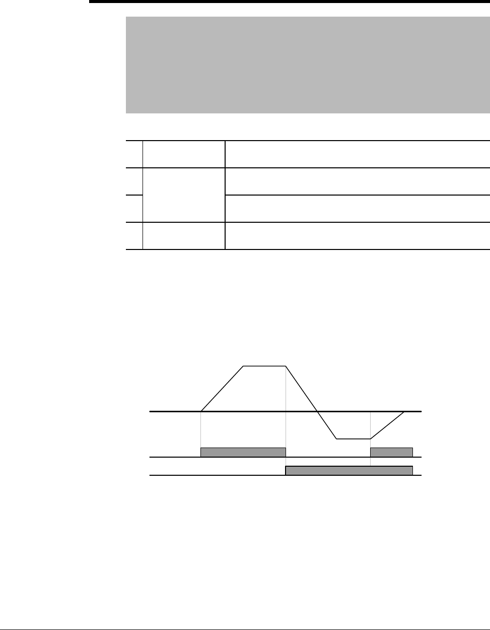
Digital/Relay Output On/Off Delay
A timer function has been implemented by adding four new software parameters.
Two are for the On Delay and two for the Off Delay timer to the digital outputs of the
VS1MD drive. Setting a value of greater than zero will begin the On, Off or both
timers when the condition set in t32 and t33 for the digital outputs is met.
In the case of the On delay timer, the actual output will not change state until the
time value set in t50 to t51 is met. The Condition set in t32 to t33 must be active
when the timer is reached for the output state to change.
In the case of the Off delay timer, once the output state is on, it will delay turning off
after the Off delay value is reached on t52 to t53. When the Off delay time is
reached, the condition set in t32 to t33 must still be off.
t50
t51 Digital Output (MO) On Delay
Relay Output (3A - 3C) On Delay
Range: 0 to 3,600 Seconds
Default: 0
Access: Configurable
See Also: t32 and t33
Sets the on delay timer for the digital output.
t52
t53 Digital Output (MO) Off Delay
Relay Output (3A - 3C) Off Delay
Range: 0 to 3,600 Seconds
Default: 0
Access: Configurable
See Also: t32 and t33
Sets the off delay timer for the digital output.
Output
MO or Relay State
On Delay Tme On Delay Time
Output
MO or Relay State
Off Delay Time Off Delay Time

Contents I
Table of Contents
Chapter 1 Introduction
1.1 Getting Assistance from Baldor.......................................................................1-1
Chapter 2 General Information and Ratings
2.1 Identifying the Drive by Model Number ........................................................... 2-1
2.2 VS1-MD Drive Ratings, Model Numbers and Frame Sizes............................. 2-2
2.3 Storage Guidelines ..........................................................................................2-2
Chapter 3 Installing the Drive
3.1 General Requirements for the Installation Site................................................ 3-1
3.2 Mounting the Drive ..........................................................................................3-5
3.3 Watts Loss Data ..............................................................................................3-6
Chapter 4 Power Wiring
4.1 Grounding the Drive ........................................................................................ 4-1
4.2 Connecting Peripheral Devices to the VS1-MD Drive ..................................... 4-3
4.3 Power Terminal Wiring .................................................................................... 4
4.4 Specifications for Power Terminal Block Wiring .............................................4-5
4.5 Recommended Breakers................................................................................. 4
4.6 Recommended AC Reactors........................................................................... 4-6
Chapter 5 Control Wiring
5.1 Stop Circuit Requirements............................................................................... 5-1
5.2 Motor Start/Stop Precautions ..........................................................................5-2
5.3 Terminal Wiring (Control I/O)........................................................................... 5-3
5.4 Control Terminal Specifications.......................................................................5
5.5 Source/Sync for Input Control Wiring .............................................................. 5-5
5.6 I/O Wiring Recommendations..........................................................................5-6
5.7 Technical Specifications.................................................................................. 5-6
Chapter 6 Using the Keypad
6.1 Keypad Components ....................................................................................... 6-1
6.2 LED Descriptions............................................................................................. 6-2
6.3 Key Descriptions.............................................................................................. 6-2
6.4 About Parameters............................................................................................ 6-3
6.5 How Parameters are Organized...................................................................... 6-4
6.6 Moving Between Parameter Groups ............................................................... 6-4
6.7 Changing Between Parameters Within a Group.............................................. 6-6
6.8 Modifying the Value of a Parameter ................................................................6-8
6.9 Monitoring Display Parameters ..................................................................... 6-10
6.10 Reviewing the Fault Status in the Display Group .......................................... 6-11
6.11 Resetting the Parameters to Factory Default ................................................6-12
Chapter 7 Parameter Descriptions
7.1 Overview.......................................................................................................... 7-1
7.2 Display Group Parameters .............................................................................. 7-2
7.3 Basic Group Parameters ................................................................................. 7-5
7.4 Terminal Paramters....................................................................................... 7-12
7.5 Function Group 1 Parameters ....................................................................... 7-28
7.6 Function Group 2 Paramters ......................................................................... 7-40

II VS1MD User Manual
Chapter 8 Customizing for Your Application
8.1 Frequency Mode ..............................................................................................8-1
8.2 UP-Down..........................................................................................................8
8.3 3-Wire ..............................................................................................................8
8.4 PID Control.....................................................................................................8
8.5 Auto-tuning.....................................................................................................8-
8.6 Sensorless Vector Control .............................................................................8
8.7 Speed Search ...............................................................................................8
8.8 Self-Diagnostic Function ................................................................................8-17
8.9 Parameter Read/Write ...................................................................................8
8.10 Parameter Initialization / Lock........................................................................8-19
8.11 Multi-function Output Terminal (MO) and Relay (3AC) ..................................8
8.12 Accel/Decel setting and V/F Control ..............................................................8-27
8.13 Control Block Diagram ...................................................................................8-28
8.14 Frequency and Drive Mode Setting................................................................8-29
Chapter 9 Troubleshooting
9.1 Verifying that DC Bus Capacitors are Discharged Before
Servicing the Drive..........................................................................................9-1
9.2 Determining Drive Status Using the STP/FLT LED..........................................9-2
9.3 Monitoring Drive Status Using the Display Parameters ...................................9-2
9.4 Reviewing Fault Status of the Drive.................................................................9-3
9.5 Fault Codes......................................................................................................9-3
9.6 Fault Correction................................................................................................9-6
9.7 Overload Protection .........................................................................................9-8
Appendix A Technical Specifications........................................................................................ A-1
Appendix B Options & Kits
B.1 Remote Option................................................................................................ B-1
B.2 Conduit Kit....................................................................................................... B-4
B.3 Breaking Resistor............................................................................................ B-8
Appendix C RS485 Protocol
C.1 Introduction .....................................................................................................C-1
C.2 Specifications..................................................................................................C-2
C.3 Installation....................................................................................................... C-3
C.4 Operation ........................................................................................................C-3
C.5 Communication Protocol (MODMUS-RTU).....................................................C-4
C.6 Communication Protocol (LS BUS).................................................................C-4
C.7 Troubleshooting .............................................................................................. C-7

Introduction 1-1
CHAPTER 1
Introduction
This manual is intended for qualified electrical personnel familiar with installing,
programming, and maintaining AC Drives.
This manual contains information on:
•Installing and wiring the VS1MD drive
•Programming the drive
•Troubleshooting the drive
1.1 Getting Assistance from Baldor
For technical assistance, call 1-864-284-5444. Before calling, please review the
troubleshooting section of this manual and check the Baldor Drives website at
www.reliance.com/vsdrives for additional information. When you call technical
support, you will be asked for the drive model number or catalog number and this
instruction manual number.

1-2 VS1MD AC Drive User Manual
General Information and Ratings 2-1
CHAPTER 2
General Information and Ratings
The VS1MD is a variable frequency PWM drive capable of operating in open-loop,
volts-per-hertz mode and in a sensorless vector control (SVC) mode.
This chapter contains information about the VS1MD drive, including how to identify
the drive.
2.1 Identifying the Drive by Model Number
Each drive can be identified by its model number, as shown in figure 2.1. The model
number is on the shipping label and the drive nameplate. The model number includes
the drive and any options.
Drive model numbers for the VS1MD drive are provided in table 2.1.
Figure 2.1 – Identifying the Drive by Model Number
VS1 MD 4 10
HP
0P5 = 0.5HP
1 = 1HP
2 = 2HP
3 = 3HP
5 = 5HP
7 = 7.5 HP
10 = 10HP
Voltage:
2 = 230V
4 = 460V
Family
MD = Microdrive

2-2 VS1MD AC Drive User Manual
2.2 VS1MD Drive Ratings, Model Numbers and Frame
Sizes
Similar VS1MD drive sizes are grouped into frame sizes to simplify re-ordering and
dimensioning. Refer to figures 3.2 through 3.5 for the dimensions of each frame size.
Table 2.1 provides VS1MD drive ratings, model numbers and frame sizes.
2.3 Storage Guidelines
If you need to store the drive, follow these recommendations to prolong drive life and
performance:
•Store the drive within an ambient temperature range of -40o to +70 Co.
•Store the drive within a relative humidity range of 0% to 90%, non-condensing.
Do not expose the drive to a corrosive atmosphere.
Table 2.1 – Drive Ratings, Model Numbers and Frame Sizes
Drive Ratings Model Number Frame
Size
Input Voltage kW HP Output
Current
200-230V
3-Phase
0.4 0.5 2.5 VS1MD20P5 A
0.75 1.0 4.5 VS1MD21 A
1.5 2.0 8.0 VS1MD22 B
2.2 3.0 12.0 VS1MD23 C
3.7 5.0 17.0 VS1MD25 C
5.5 7.5 24.0 VS1MD27 D
7.5 10 32.0 VS1MD210 D
380-480V
3-Phase
0.4 0.5 1.25 VS1MD40P5 A
0.75 1.0 2.5 VS1MD41 A
1.5 2.0 4.0 VS1MD42 B
2.2 3.0 6.0 VS1MD43 C
3.7 5.0 8.0 VS1MD45 C
5.5 7.5 12.0 VS1MD47 D
7.5 10.0 16.0 VS1MD410 D

Installing the Drive 3-1
CHAPTER 3
Installing the Drive
This chapter provides information that must be considered when planning a VS1MD
drive installation and provides drive mounting information and installation site
requirements.
3.1 General Requirements for the Installation Site
It is important to properly plan before installing a VS1MD to ensure that the drive’s
environment and operating conditions are satisfactory.
The area behind the drive must be kept clear of all control and power wiring. Power
connections may create electromagnetic fields that may interfere with control wiring or
components when run in close proximity to the drive.
Read the recommendations in the following sections before continuing with the drive
installation.
!
ATTENTION: Only qualified electical personnel familiar with the
construction and operation of this equipment and the hazards involved
should install, adjust, operate, or service this equipment. Read and
understand this manual and other applicable manuals in their entirety
before proceeding. Failure to observe this precaution could result in
severe bodily injury or loss of life.
ATTENTION: Use of power correction capacitors on the output of
the drive can result in erratic operation of the motor, nuisance tripping,
and/or permanent damage to the drive. Remove power correction
capacitors before proceeding. Failure to observe this precaution could
result in damage to, or destruction of, the equipment.
ATTENTION: The user is responsible for conforming with all
applicable local, national, and international codes. Failure to observe
this precaution could result in damage to, or destruction of, the
equipment.
3-2 VS1MD AC Drive User Manual
3.1.1 Operating Conditions
Before deciding on an installation site, consider the following guidelines:
•Protect the cooling fan by avoiding dust or metallic particles.
•Do not expose the drive to a corrosive atmosphere.
•Protect the drive from moisture and direct sunlight.
•Verify that the drive location will meet the environmental conditions specified in table
3.1.
3.1.2 Minimum Mounting Clearances
Refer to figure 3.1 for the minimum mounting clearances. Refer to section 3.1 for drive mounting
dimensions.
Table 3.1 – Ambient Temperatures and Mounting Clearances
Ambient Temperature Enclosure Rating Minimum Mounting
Clearances
Minimum Maximum
-10o C
(14o F)
50o C
(122o F)
IP20/Open Type 5 cm
40o C
(104o F)
IP20/NEMA 1 5 cm
50o C
(122o F)
Side-by-Side 5 cm
Figure 3.1 – Minimum Mounting Clearances
5 cm
(1.0 in)
Installing the Drive 3-3
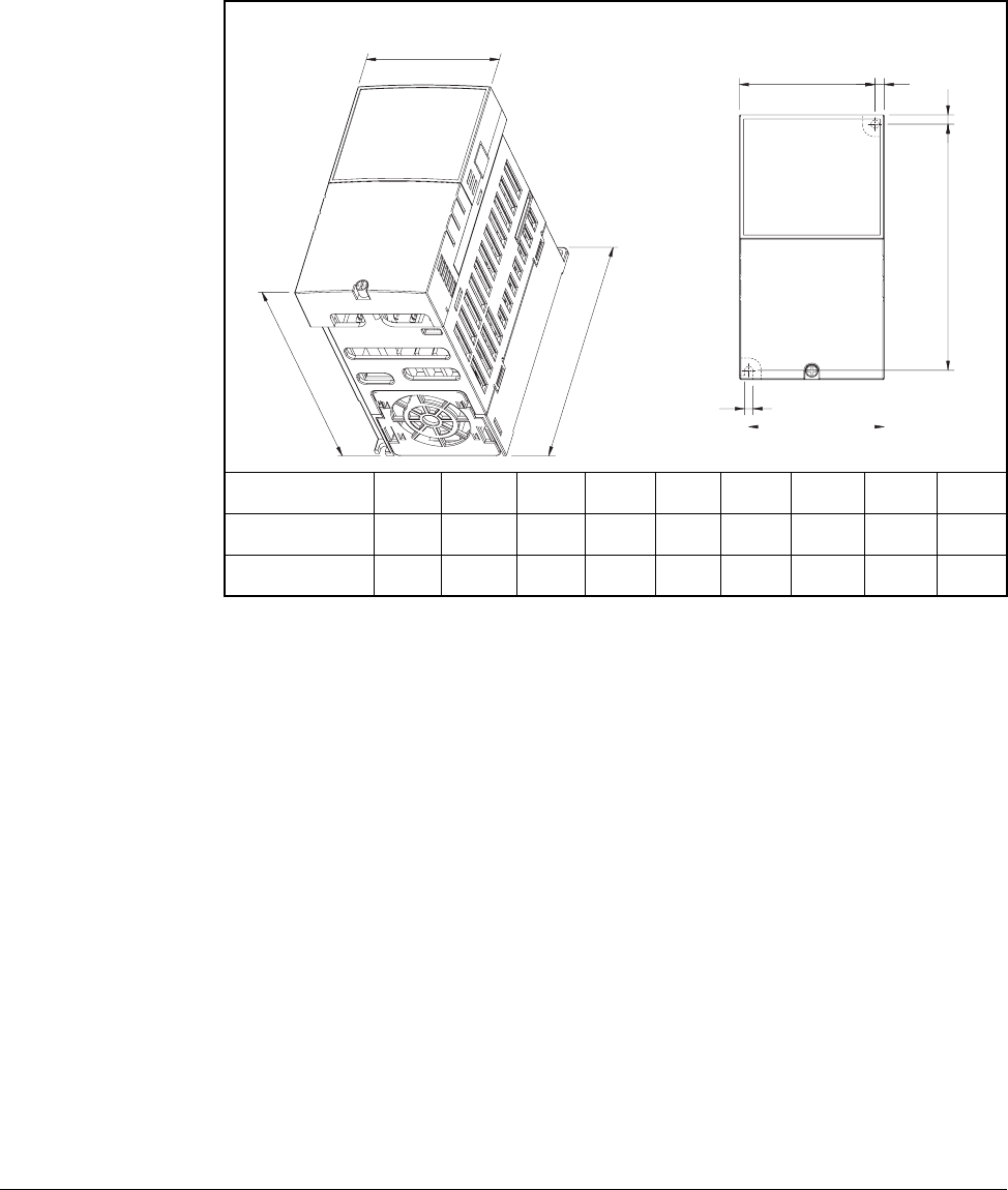
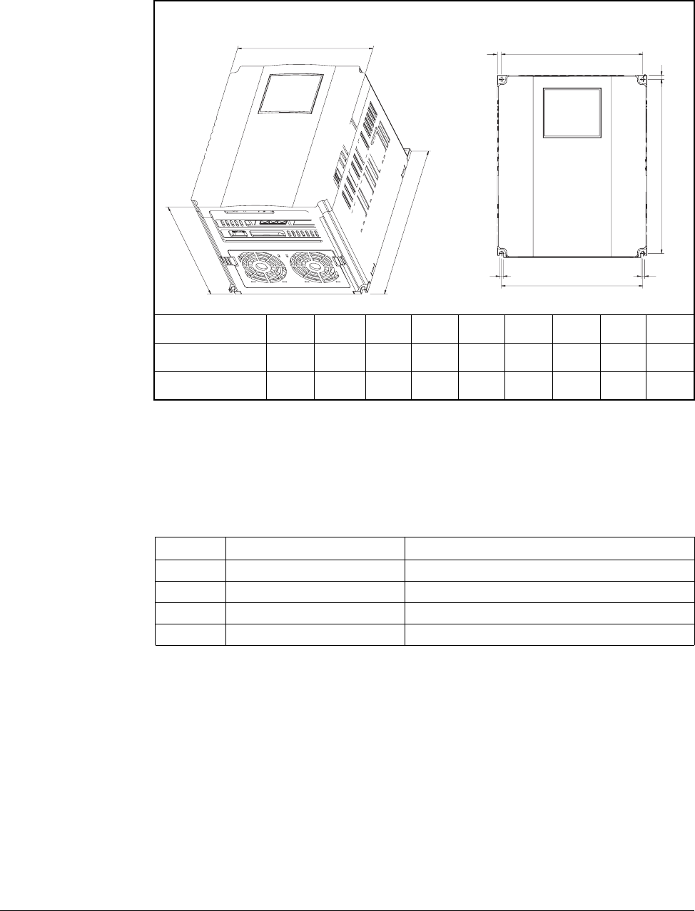
3.1.3 Mounting Dimensions for the VS1MD Drive
Overall dimensions and weights are illustrated in figures 3.2, 3.3, 3.4 and 3.5 as an aid to
calculating the total area required by the VS1-MD drive. Dimensions are in millimeters. Weights
are in kilograms. See table 2.1 for drive ratings by frame.
Frame Size A HP W W1 H H1 D A B kg
230V/460V 0.5 70 65.5 128 119 130 4.5 4.0 0.76
230V/460V 1.0 70 65.5 128 119 130 4.5 4.0 0.77
Figure 3.2 – Drive Dimensions and Weights Frame A
W
W1
A
D
H
W1
B
H1
A
3-4 VS1MD AC Drive User Manual
Frame Size B HP W W1 H H1 D A B kg
230V/460V 2.0 100 95.5 128 120 130 4.5 4.5 1.12
Figure 3.3 – Drive Dimensions and Weights Frame B
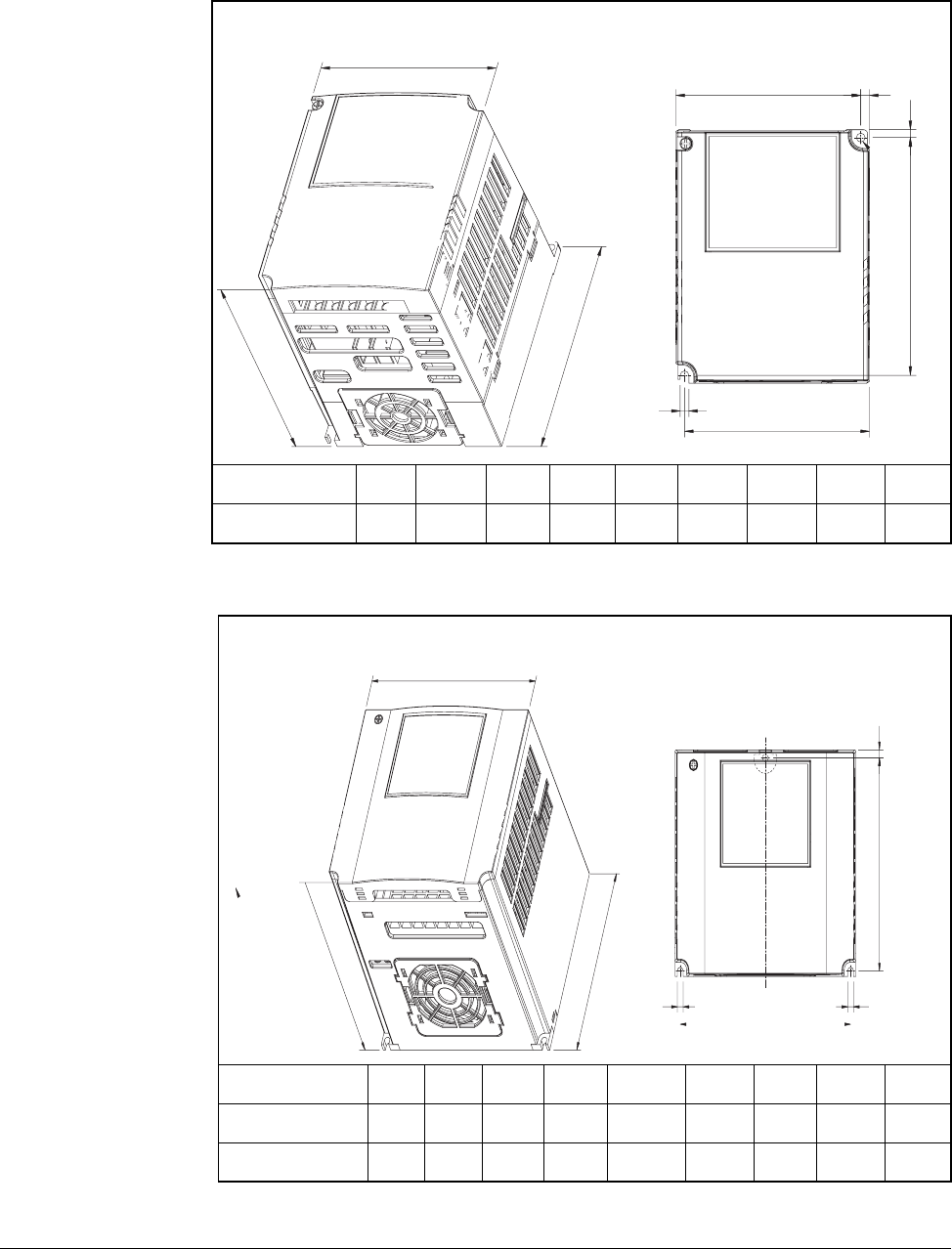
Frame Size C HP W W1 H H1 D A B kg
230V/460V 3.0 140 132 128 120.5 155 4.5 4.5 1.84
230V/460V 5.0 140 132 128 120.5 155 4.5 4.5 1.89
Figure 3.4 – Drive Dimensions and Weights Frame C
W
W1
D
H
H1
W1
B
A
A
W
W1
DH
H1
A
B
B
Installing the Drive 3-5
3.2 Mounting the Drive
Mount the drive upright on a flat, vertical, and level surface.
3.2.1 Protecting the Drive from Debris
The drive must be protected from debris falling through the vents in the top of the drive
during installation and operation. The drive is designed to operate in IP20/Open Type
application mounted in a protective enclosure. A conduit kit is available as an option
which provides a top panel to block the top vents and prevent debris from entering the
drive.
Frame Size D HP W W1 H H1 D A B kg
230V/460V 7.5 180 170 220 210 170 5.0 4.5 3.66
230V/460V 10.0 180 170 220 210 170 5.0 4.5 3.66
Figure 3.5 – Drive Dimensions and Weights Frame D
WW
A
A
D
W1
H
H1
BB
Table 3.1 – Mounting Specifications
Frame Screw Size Screw Torque
A M3.5 (#6-32) 0.67 - 0.97 N-m (6 - 8 in-lb)
B M4 (#8-32) 1.56 - 1.96 N-m (14 -17 in-lb)
C M4 (#8-32) 1.56 - 1.96 N-m (14 -17 in-lb)
D M4 (#8-32) 1.56 - 1.96 N-m (14 -17 in-lb)

3-6 VS1MD AC Drive User Manual
3.3 Watts Loss Data
Table 3.2 – Watts Loss Data
Model # HP Frame Watts Loss
230 Volts
VS1MD20P5 0.5 A 13
VS1MD21 1.0 A 28
VS1MD22 2.0 B 18
VS1MD23 3.0 C 56
VS1MD25 5.0 C 98
VS1MD27 7.5 D 73
VS1MD210 10.0 D 70
460 Volts
VS1MD40P5 0.5 A 9
VS1MD41 1.0 A 22
VS1MD42 2.0 B 32
VS1MD43 3.0 C 47
VS1MD45 5.0 C 94
VS1MD47 7.5 D 84
VS1MD410 10.0 D 113
Power Wiring 4-1
CHAPTER 4
Power Wiring
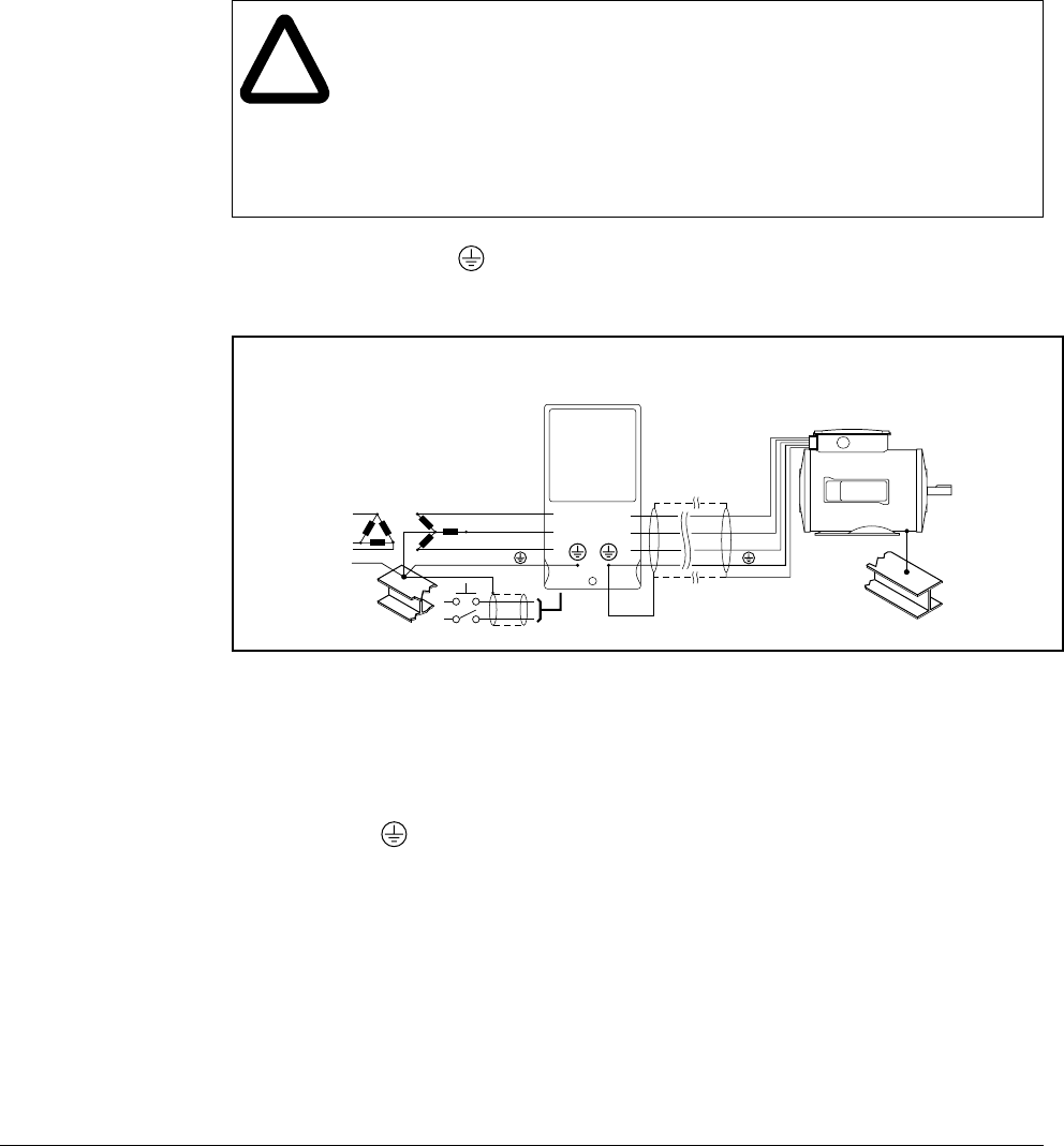
4.1 Grounding the Drive
The drive Safety Ground - must be connected to system ground. Ground impedance must
conform to the requirements of national and local industrial safety regulations and/or electrical
codes. The integrity of all ground connections should be periodically checked.
Ground Fault Monitoring
If a system ground fault monitor is to be used, only Type B devices should be used to
avoid nuisance tripping.
Safety Ground -
This is the safety ground for the drive that is required by code. One of these points must be
connected to adjacent building steel (girder, joist), a floor ground rod, or bus bar. Grounding
points must comply with national and local industrial safety regulations and/or electrical codes.
Motor Ground
The motor ground must be connected to one of the ground terminals on the drive.
!
ATTENTION:The following information is merely a guide for proper
installation. Baldor Electric Company cannot assume responsibility for
the compliance or the noncompliance to any code, national, local or
otherwise for the proper installation of this drive or associated equipment.
A hazard of personal injury and/or equipment damage exists if codes are
ignored during installation.
ATTENTION:Use the dedicated ground terminal to ground the drive. Do
not use the screw in the case or chassis, etc for grounding.
Figure 4.1 – Typical Grounding
SHLD
U
V
W
R
S
T

4-2 VS1MD AC Drive User Manual
Shield Termination - SHLD
Either of the safety ground terminals provides a grounding point for the motor cable shield. The
motor cable shield connected to one of these terminals (drive end) should also be connected to
the motor frame (motor end). Use a shield terminating or EMI clamp to connect the shield to the
safety ground terminal.
When shielded cable is used for control and signal wiring, the shield should be grounded at
the source end only, not at the drive end.
4.1.1 RFI Filter Grounding
Using drives with RFI filters may result in relatively high ground leakage currents. Therefore, the
filter must only be used in installations with grounded AC supply systems and be
permanently installed and solidly grounded (bonded) to the building power distribution
ground.
Ensure that the incoming supply neutral is solidly connected (bonded) to the same building
power distribution ground. Grounding must not rely on flexible cables and should not include
any form of plug or socket that would permit inadvertent disconnection. Some local codes may
require redundant ground connections. The integrity of all connections should be periodically
checked.
4.1.2 Grounding Procedure
Step 1. Remove the front cover.
Step 2. Connect the Grounding wire to the ground terminal through the opening for
ground terminal. Enter the screw driver from vertical to the terminal and
secure the screw tightly.
4.1.3 Grounding Guidelines
Table 4.1 – Grounding Guidelines
Inverter
capacity
200V Class 400V Class
Wire
size Terminal
screw Grounding
method Wire
size Terminal
screw Grounding
method
0.5 HP 3.5 mm2M3 Type 3 2 mm2M3 Special Type 3
1.0 HP 3.5 mm2M3 2 mm2M3
2.0 HP 3.5 mm2M3 2 mm2M3
3.0 HP 3.5 mm2M3 2 mm2M3
7.5 HP 5.5 mm2M4 3.5 mm2M4
Power Wiring 4-3
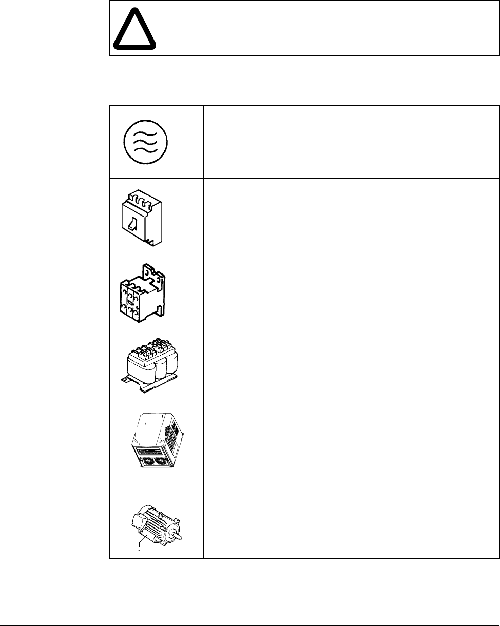
4.2 Connecting Peripheral Devices to the VS1MD Drive
The following devices are required to operate the VS1MD drive.
!
ATTENTION:Appropriate peripheral devices must be selected and
correct connections made to ensure proper operation. You must read and
understand this manual thoroughly before proceeding. Failure to observe
this precaution could result in damage to, or destruction of, the equipment.
Table 4.2 – Peripheral Devices for the VS1MD Drive
AC Source Supply Use a power supply within the
permissible range for the drive’s
input power rating.
MCCB or Earth leakage
circuit breaker (ELB) Select circuit breakers with care. A
large inrush current may flow in the
converter when power is turned on.
Magnetic Contactor Install a magnetic contactor if
necessary. When installed, do not
use the contactor for the purpose of
starting or stopping.
Reactors Reactors must be used when the
power factor needs to be improved
or the drive is installed within 10 m
of a large power supply system
(1000kVA or more).
Installation and wiring To ensure optimal operation and
life span of the drive, install it in an
approriate place with proper
orientation and clearances.
Incorrect terminal wiring can result
in damage to the equipment.
To motor Do not connect a power factor
capacitor, surge suppresor, or radio
noise filter to the output side of the
drive.
4-4 VS1MD AC Drive User Manual
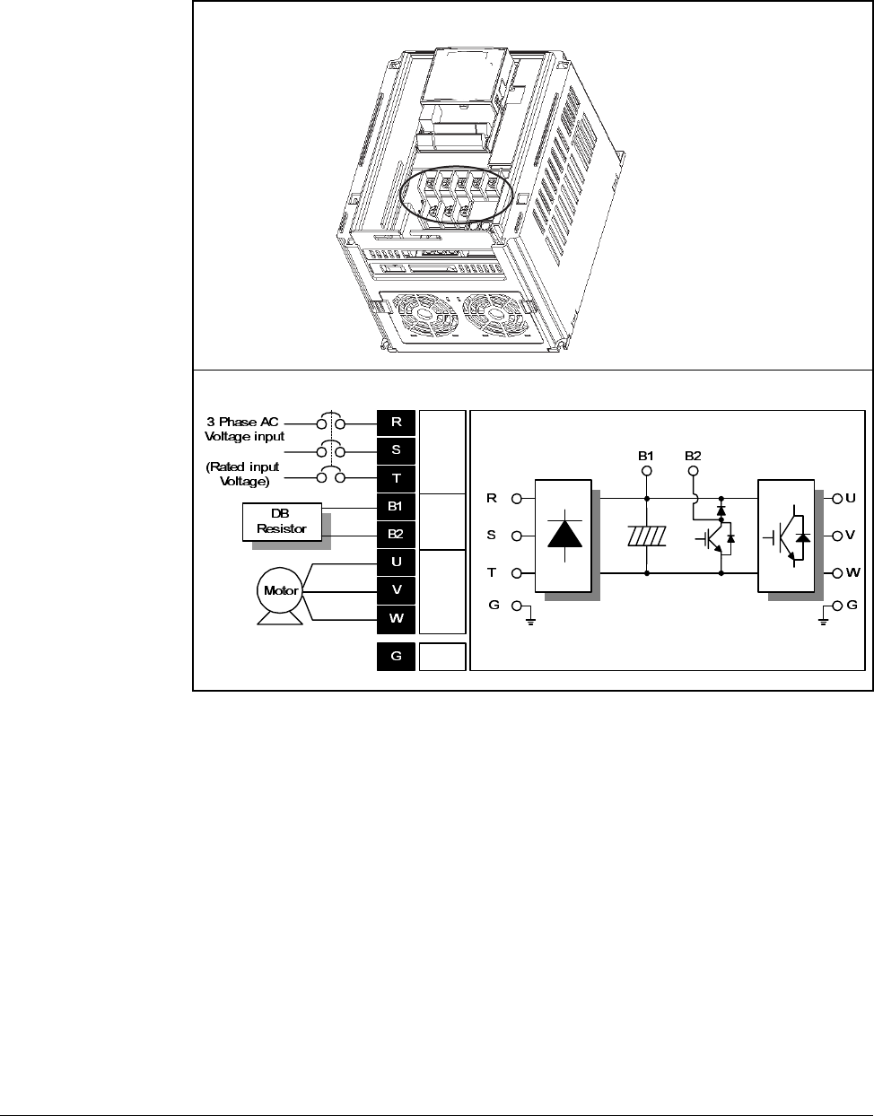
4.3 Power Terminal Wiring
Figure 4.2 – Power Terminal Wiring
AC Line
Voltage
input
DB
reistor
connect
ion
terminal
Motor
connect
ion
terminal
Ground
Power Wiring 4-5
4.4 Specifications for Power Terminal Block Wiring
VS1MD20P5, VS1MD21, VS1MD40P5, VS1MD41, VS1MD22, VS1MD42
VS1MD23, VS1MD43, VS1MD25, VS1MD45
VS1MD27, VS1MD210, VS1MD47, VS1MD410
* Strip the sheaths of the wire insulation 7mm when a ring terminal is not used for
power connection.
RSTB1B2
UVW
RSTB1B2UVW
B1 B2 U V W
RST
Model
Number
R,S,T
wire size U, V, W
wire size Ground Wire Screw
size Terminal
torque
mm2AWG mm2AWG mm2AWG Terminal
Screw
Size
Screw
Torque
(Kgf.cm/lb-in)
VS1MD20P5 2 14 2 14 3.5 12 M3.5 10/8.7
VS1MD21 2 14 2 14 3.5 12 M3.5 10/8.7
VS1MD22 2 14 2 14 3.5 12 M3.5 10/8.7
VS1MD23 2 14 2 14 3.5 12 M4 15/13
VS1MD25 3.5 12 3.5 12 3.5 12 M4 15/13
VS1MD27 5.5 10 5.5 10 5.5 10 M5 32/28
VS1MD10 8 8 8 8 5.5 10 M5 32/28
VS1MD40P5 2 14 2 14 2 14 M3.5 10/8.7
VS1MD41 2 14 2 14 2 14 M3.5 10/8.7
VS1MD42 2 14 2 14 2 14 M4 15/13
VS1MD43 2 14 2 14 2 14 M4 15/13
VS1MD45 2 14 2 14 2 14 M4 15/13
VS1MD47 3.5 12 2 14 3.5 12 M5 32/28
VS1MD410 3.5 12 3.5 12 3.5 12 M5 32/28
4-6 VS1MD AC Drive User Manual
4.5 Recommended Breakers
4.6 Recommended Fuses and AC Reactors
Table 4.3 – Circuit Breaker Ratings by Model Number
Model Breaker Model Breaker
Current[A] Voltage[V] Current[A] Voltage[V]
VS1MD20P5 30 230 VS1MD40P5 30 460
VS1MD21 30 230 VS1MD41 30 460
VS1MD22 30 230 VS1MD42 30 460
VS1MD23 30 230 VS1MD43 30 460
VS1MD25 30 230 VS1MD45 30 460
VS1MD27 50 230 VS1MD47 30 460
VS1MD10 60 230 VS1MD410 30 460
Model External fuse AC reactor
Current[A] Voltage[V]
VS1MD20P5 10 A 500 4.20mH, 3.5A
VS1MD21 10 A 500 2.13mH, 5.7A
VS1MD22 15 A 500 1.20mH, 10A
VS1MD23 25 A 500 0.88mH,14A
VS1MD25 40 A 500 0.56mH, 20A
VS1MD27 40 A 500 0.39mH, 30A
VS1MD210 50 A 500 0.28mH, 40A
VS1MD40P5 5 A 500 18.0mH, 1.3A
VS1MD41 10 A 500 8.63mH, 2.8A
VS1MD42 10 A 500 4.81mH, 4.8A
VS1MD43 10 A 500 3.23mH, 7.5A
VS1MD45 20 A 500 2.34mH, 10A
VS1MD47 20 A 500 1.22mH, 15A
VS1MD4100 30 A 500 1.14mH, 20A
!
ATTENTION:Suitable For Use On A Circuit Capable Of Delivering
Not More Then 65,000 RMS Symmetrical Amperes. 240V drives
or 480V drives Volts Maximum
ATTENTION:Use Class H or K5 UL Listed Input Fuse and UL
Listed Breaker Only. See the table above for the voltage and current
rating of the fuse and the breaker.

Power Wiring 4-7
4.7 Reflected Wave Protection
When more than one motor is connected to one inverter, total wiring length should be
less than 200m (656ft). Do not use a 3-wire cable for long distances. Due to increased
leakage capacitance between wires, over-current protective feature may operate or
equipment connected to the output side may malfunction. In case of long wire length,
lower carrier frequency or contact Baldor for recommendations.
Table 4.4 – Wire Length Recommendations
Length Between Inverter and Motor Allowable Carrier Frequency
Up to 50 meters Less than 15 kHz
Up to 100 meters Less than 5 kHz
More than 100 meters Less than 2.5 kHZ

4-8 VS1MD AC Drive User Manual
Control Wiring 5-1
CHAPTER 5
Control Wiring
This chapter describes how to wire the signal and I/O terminal strip for stop, speed
feedback, and remote control signals.
5.1 Stop Circuit Requirements
In addition to the operational stop, you must provide a hardwired emergency stop
external to the drive. The emergency stop circuit must contain only hardwired
electromechanical components. Operation of the emergency stop must not depend on
electronic logic (hardware or software) or on the communication of commands over an
electronic network or link. Note that the hardwired emergency stop you install can be
used at any time to stop the drive.
!
ATTENTION:Apply the rated torque to terminal screws. Loose screws
can cause short circuit and malfunction. Tightening the screws too much
can damage the terminals and cause short circuit and malfunction.
ATTENTION:Make sure the input power is off before wiring.
ATTENTION:After power supply is switched off following operation, wait
at least 10 minutes after LED keypad display is off before you start
working on it.
ATTENTION:Applying input power supply to the output terminals U, V
and W causes internal inverter damage.
ATTENTION:Use ring terminals with insulated caps when wiring the
input power and motor wiring.
ATTENTION:Do not leave wire fragments inside the inverter. Wire
fragments can cause faults, breakdowns and malfunctions.
ATTENTION:When more than one motor is connected to one inverter,
total wiring length should be less than 200m (656ft). Do not use a 3-wire
cable for long distances. Due to increased leakage capacitance between
wires, over-current protective feature may operate or equipment
connected to the output side may malfunction. In case of long wire
length, lower carrier frequency or contact Baldor for recommendations.
ATTENTION:Never short B1 and B2 terminals. Shorting terminals may
cause internal inverter damage.
ATTENTION:Do not install a power factor capacitor, surge suppressor
or RFI filter in the output side of the inverter. Doing so may damage
these components.
!
ATTENTION:You must provide an external, hardwired emergency
stop circuit outside of the drive circuitry. This circuit must disable the
system in case of improper operation. Uncontrolled machine
operation can result if this procedure is not followed. Failure to observe
this precaution could result in bodily injury.
5-2 VS1MD AC Drive User Manual
5.2 Motor Start/Stop Precautions
Important points to remember about I/O wiring:
•Always use copper wire.
•Wire with an insulation rating of 600V or greater is recommended.
•Control and signal wires should be separated from power wires by at least 0.3
meters (1 foot).
Important: I/O terminals labeled “Common” are not referenced to the safety ground
terminal and are designed to greatly reduce common mode interference.
!
ATTENTION:A contactor or other device that routinely disconnects and
reapplies the AC line to the drive to start and stop the motor can cause
drive hardware damage. The drive is designed to use control input
signals that will start and stop the motor. If used, the input device must
not exceed one operation per minute or drive damage can occur. Failure
to observe this precaution can result in damage to, or destruction of,
equipment.
ATTENTION:The drive start/stop control circuitry includes solid-state
components. If hazards due to accidental contact with moving
machinery or unintentional flow of liquid, gas or solids exist, an
additional hardwired stop circuit may be required to remove the AC line
to the drive. When the AC line is removed, there will be a loss of any
inherent regenerative braking effect that might be present - the motor
will coast to a stop. An auxiliary braking method may be required.
!
ATTENTION:Driving the 4-20 mA analog input from a voltage source
could cause component damage. Verify proper configuration prior to
applying input signals.
Control Wiring 5-3
5.3 Terminal Wiring (Control I/O)
T/M Description
MO Multi-function open collector output
MG MO Common
24 24V output
P1 FX: Forward run
P2
MF input terminal
(factory setting) RX: Reverse run
CM Input signal common
P3 BX: Stop
P4 RST: Trip reset
P5
MF input terminal
(factory setting)
JOG: Jog operation
CM Input signal common
P6
P7
P8
MF input terminal
(factory setting)
VR 10V power supply for potentiometer
V1 Freq. Setting Voltage signal input: -0~10V
IFreq. Setting Current signal input: 0~20mA
AM Multi-function analog output signal: 0~10V
3A A contact output N.O.
3B B contact output N.C.
3C
Multi-function relay
output terminal
A/B contact common
S+
S- RS485 communication terminal
G
#For connection to Remote Option or
parameter copying
Preset Speed Input 1
Preset Speed Input 2
Preset Speed Input 3

5-4 VS1MD AC Drive User Manual
5.4 Control Terminal Specifications
MO MG 24 P1 P2 CM P3 P4 S- S+
3A 3B 3C P5 CM P6 P7 P8 VR V1 I AM
T/M Terminal Description Wire size[mm2]Screw
size Torque
[Nm] Specification
solid
wire stranded
P1
to
P8
Multi-function digital input
T/M 1-8 1.0 1.5 M2.6 0.4
CM Common Terminal 1.0 1.5 M2.6 0.4
VR Power supply for external
speed potentiometer 1.0 1.5 M2.6 0.4 Output Voltage: 12 V
Max output current: 10mA
Potentiometer: 1 - 5 kohm
V1 Input terminal for Voltage
operation 1.0 1.5 M2.6 0.4 Max input voltage:
-12V - +12V input
I Input terminal for Current
operation 1.0 1.5 M2.6 0.4 0 - 20 mA input
Internal Resister: 250 ohm
AM Multi-function analog
output terminal 1.0 1.5 M2.6 0.4 Max output voltage: 11 V
Max output current:
100mA
MO Multi-function terminal for
open collector output 1.0 1.5 M2.6 0.4 Below DC 26V, 100mA
MG Ground terminal for
external power supply 1.0 1.5 M2.6 0.4
24 24V External Power
Supply 1.0 1.5 M2.6 0.4 Max output current:
100mA
3A Multi-function relay
output A contact N.O. 1.0 1.5 M2.6 0.4 Below AC 250V, 1A
3B Multi-function relay
output B contact N.C. 1.0 1.5 M2.6 0.4 Below DC 30V, 1A
3C Common for
Multi-function relays 1.0 1.5 M2.6 0.4
Control Wiring 5-5
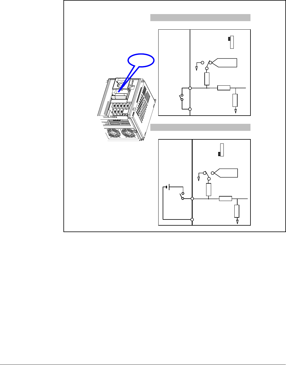
5.5 Source/Sync for Input Control Wiring
2. When using external DC 24V [Sink ]
1. When using DC 24V inside inverter [Source]
SW S8
DC 24 V
P1
CM
CM
S8
SW S8
RG
R
RG
CM
CPU
(inside inverter)
DC 24 V
P1
CM
CM
S8
DC24V
SW S8
RG
R
R
CM
CPU
( i ns ide i nv e rt er)
Sink (PNP)
Source
(NPN)

5-6 VS1MD AC Drive User Manual
5.6 I/O Wiring Recommendations
5.6.1 Maximum Control Wire Length Recommendations
Do not exceed control wiring length of 30 meters (100 feet). Control signal cable
length is highly dependent on electrical environment and installation practices. To
improve noise immunity, the I/O terminal block Common must be connected to ground
terminal/protective earth.
5.7 Technical Specifications
Please see Appendix A - Technical Specifications for detailed electrical information.
Table 5.1 – Recommended Control and Signal Wire1
1If the wires are short and contained within a cabinet that has no sensitive circuits,
the use of shielded wire may not be necessary, but is always recommended.
Wire Type(s) Description
Minimum
Insulation
Rating
Belden 8760/9460
(or equiv.) 0.8 mm2 (18AWG), twisted pair, 100% shield with drain. 300 V
75° C
(167° F)
Belden 8770
(or equiv.) 0.8 mm2(18AWG), 3 conductor, shielded for remote pot
only.
Table 5.2 – I/O Terminal Block Specifications
Maximum Wire Size1
1Maximum / minimum that the terminal block will accept. These are not
recommendations.
Minimum Wire Size1Torque
1.3 mm2 (16 AWG) 0.13 mm2 (26 AWG) 0.5 to 0.8 Nm
(4.4 in-lb to 7 in-lb)
Using the Keypad 6-1
CHAPTER 6
Using the Keypad
Factory-default parameter values allow the drive to be controlled from the integral
keypad. No programming is required to start, stop, change direction, or control speed
directly from the integral keypad.
This chapter provides an overview of the integrated keypad and how to use it to
program the VS1MD drive.
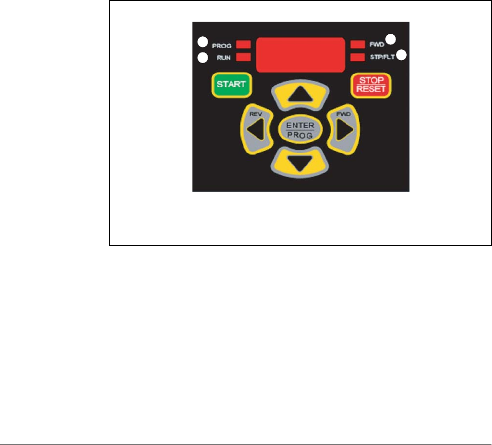
6.1 Keypad Components
6.1.1 Display Description
The alpha-numeric display indicates the following:
•Operational Values (such as Output Frequency)
•Parameter Numbers
•Parameter Values
•Fault Codes
Refer to table 6.1 for the LED descriptions noted by ➊ through ➍ and table 6.2 for key definitions.
1
2
3
4
6-2 VS1MD AC Drive User Manual
6.2 LED Descriptions
Refer to figure 6.1 for the location of the LEDs described in table 6.1.
6.3 Key Descriptions
Refer to figure 6.1 for the location of the keys described in table 6.2.
Table 6.1 – LED Descriptions
No. LED LED State Description
➊PROG Steady Red (On) Indicates the drive is in programming mode.
(Off) Indicates the drive is in operational Mode.
➋RUN Steady Red (On) Indicates the drive is running at commanded speed.
Flashing Red Indicates drive is accelerating or decelerating to new
speed setting.
(Off) Drive is not running.
➌FWD Steady Red (On) Indicates the drive is in forward operation.
(Off) Indicates the drive is in reverse operation.
➍STP/FLT Steady Red (On) Indicates the drive is in a stopped position.
Flashing Red Indicates the drive is faulted.
(Off) Drive is running.
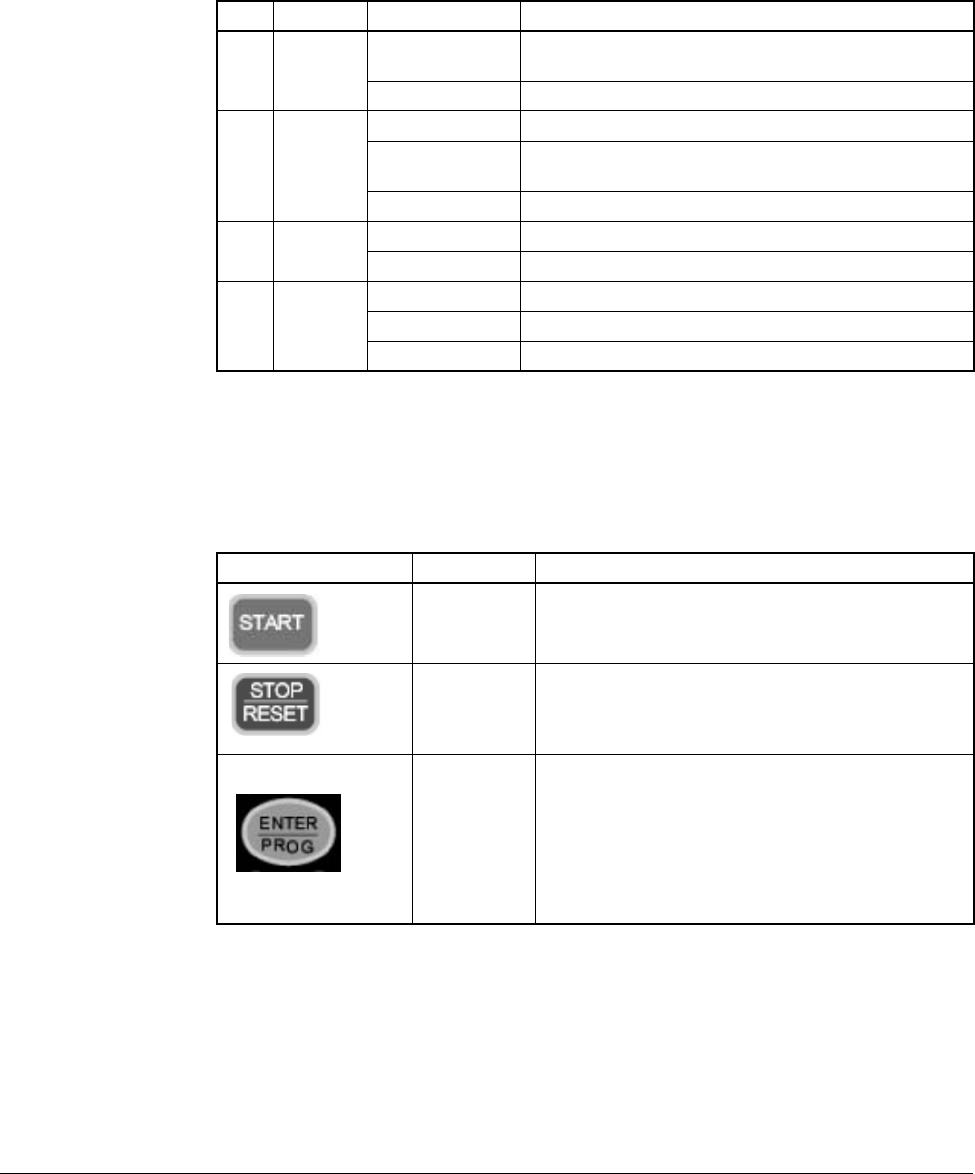
Table 6.2 – Key Descriptions
Key Name Description
Run Key •Starts the drive.
•Active when the input mode is programmed for
keypad control.
Stop Key •Stops the drive in programmed stop mode.
•Always active.
•Reset active faults.
Ent/Prog Key •Accesses programming menu and locks in
changed values.
•To enter programming mode, the Ent/Prog key
must be held in for 2 seconds.
•Holding the Ent/Prog key for 2 seconds or more will
escape back to Control Reference Mode or back
out of a parameter edit function.
Using the Keypad 6-3
6.4 About Parameters
To program the drive for a specific application, you adjust the appropriate parameters. The
parameters are used to define characteristics of the drive.
There are three types of parameters:
•Numbered List Parameters (Enumerated Parameters)
Numbered list parameters allow a selection from two or more options. Each item is
represented by a number.
Example: Start/Stop Source (P38)
•Bit Parameters
Bit parameters have individual bits associated with features or conditions. If the bit is 0, the
feature is off or the condition is false. If the bit is 1, the feature is on or the condition is true.
Example: Terminal Status Display (d7)
•Numeric Parameters
These parameters have a single numerical value (for example, 0.1 volts).
Example: Motor Rated Current (P32)
Parameters are also either configurable or tunable, or read-only.
Configurable parameters can be adjusted or changed only while the drive is stopped.
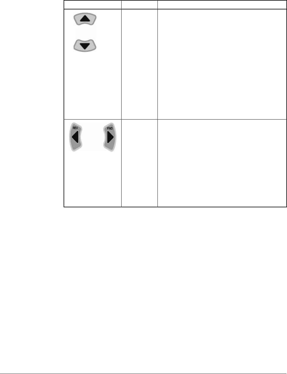
Speed
Reference
Keys
Operation Mode:
•Changes the commanded speed reference.
•Only active when the input mode is programmed for
keypad control.
•The Up-Arrow increases the speed reference at a
controlled rate.
•The Down-Arrow decreases the speed reference at
a controlled rate.
•Holding either arrow for a set period of time will
increase the reference ramp rate.
Program Mode:
•Increment / Decrement parameter numbers or
parameter values
Direction
Keys Operation Mode:
•Only active when the input mode is programmed for
keypad control.
•Direction keys are active only when operating in
reference command mode.
•Reverse may also be disabled by a parameter.
Program Mode:
•Cycle through the parameter groups or shift to
the next digit to be changed while in the
parameter edit mode.
Table 6.2 – Key Descriptions (Continued)
Key Name Description

6-4 VS1MD AC Drive User Manual
Tunable parameters can be adjusted or changed while the drive is running or stopped.
Read-only parameters cannot be adjusted.
6.5 How Parameters are Organized
Parameters are organized into five Parameter Groups:
•The Display Parameter Group (dnn) contains parameters for the display of basic
drive information.
•The Programming Parameter Group (Pnn) contains the most commonly used
parameters for startup and operation.
•The Terminal Parameter Group (tnn) contains a linear list of input and output control
parameters.
•Function Group 1 Parameters (Fnn) contains a linear list of advanced motor control
parameters.
•Function Group 2 Parameters (Hnn) contains a linear list of advanced motor profile
parameters.
6.6 Moving Between Parameter Groups
Use the following procedure to enter the programming mode and to move between
groups:
Table 6.3 – Moving Between Parameter Groups
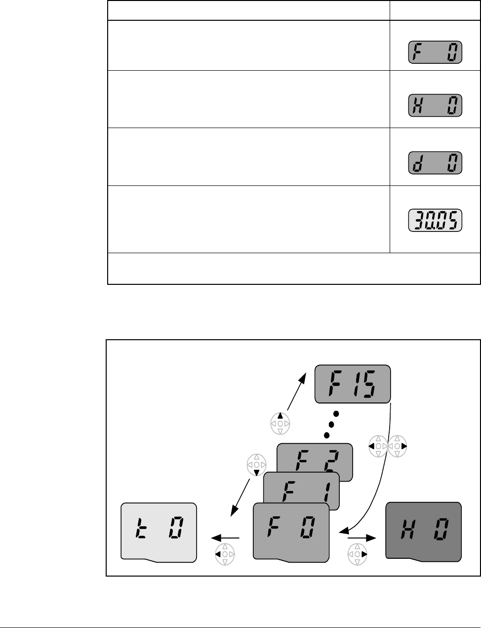
Procedure Sample Display
Step 1. When the drive first powers up, the display will
indicate the value of the “Power ON Display,” which
is defined in Parameter H72. The default “Power On
Display” is the commanded frequency.
Step 2. Press and hold down the ENTER key for at least two
seconds to change the drive from the operation
mode to the programming mode.The “PROG” LED
will illuminate indicating that the drive is in
programming mode. The drive will display the first
parameter of the “Display” group.
Step 3. Press the right arrow key to change to the
“Parameters Group”.
Step 4. Press the right arrow key to change to the “Terminal
Group”.
Using the Keypad 6-5
You can only move between groups while the first parameter of the group is displayed.
Pressing the left or right arrow while displaying any parameter other than the first
parameter of the group returns to the first parameter of the group.
Step 5. Press the right arrow key to change to “Function
Group 1”.
Step 6. Press the right arrow key to change to “Function
Group 2”.
Step 7. Press the right arrow key to change to “Display”
group.
Step 8. Press and hold down the ENTER key for at least two
seconds to change the drive from the programming
mode back to operation mode.The “PROG” LED will
go out indicating that the drive is in operation mode.
The drive will display the default “Power On Display”.
Note that the above can be execute in reverse order by using the left arrow key
instead of the right arrow key.
Table 6.3 – Moving Between Parameter Groups
Procedure Sample Display
Function Group 1 Function Group 2
Terminal group
Pressing the
left or right
arrow from
any parameter
returns you to
the first
parameter of
the group
Pressing the
up or down
arrow moves
you within a
group of
parameters
6-6 VS1MD AC Drive User Manual
The below example indicates the steps needed to move from parameter F35 to
Function Group 2.
6.7 Changing Between Parameters Within a Group
Each group contains parameters arranged in a linear list. The list can be navigated
using the Up and Down arrows.
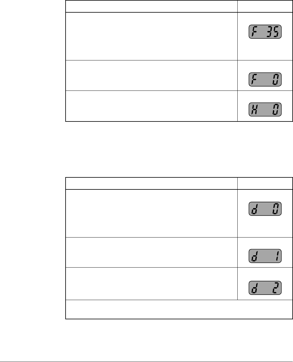
Table 6.4 – Moving from F35 to Function Group 2
Procedure Sample Display
Step 1. When a parameter other than the first in a group is
displayed, you must initially go to the first parameter
of the group prior to going to the next group. For this
example, parameter F35 of Function Group 1 is
currently displayed and you want to go to Function
Group 2 (H Parameters).
Step 2. Press the left or right arrow and parameter F0 will be
displayed.
Step 3. Press the right arrow key to change to “Function
Group 2”.
Table 6.5 – Changing Between Parameters Withing a Group
Procedure Sample Display
Step 1. From the operation mode, press and hold down the
ENTER key for at least two seconds to change the
drive to the programming mode. The “PROG” LED
will illuminate indicating that the drive is in
programming mode. The drive will display the first
parameter of the “Display” group.
Step 2. Press the up arrow to display the next parameter.
Step 3. Press the up arrow again to display the next
parameter, continue until the desired parameter is
displayed.
Note that using the down arrow allows navigation through the parameters in
reverse order.
Using the Keypad 6-7
The first parameter of each group, with the exception of the “Display Group”, is a
special parameter called a “Jump Code”. The parameter can be used to jump to a
specific parameter within a group without having to scroll through the parameters
using the up and down arrows. Once the Jump Code is programmed, the drive will
save the setting for future use, but this can always be reprogrammed to jump to a
different parameter.
The following example illustrates the use of a Jump Code to jump to parameter P38.
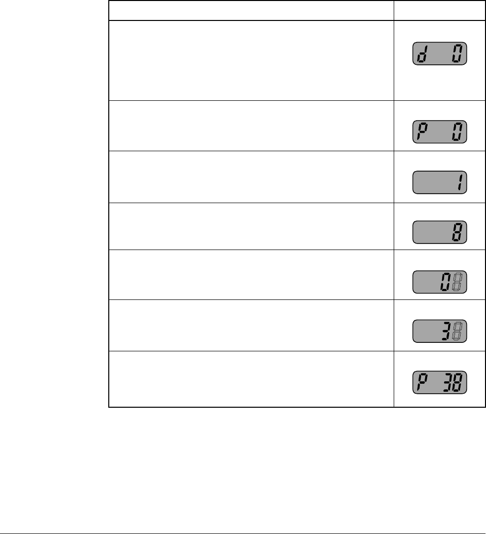
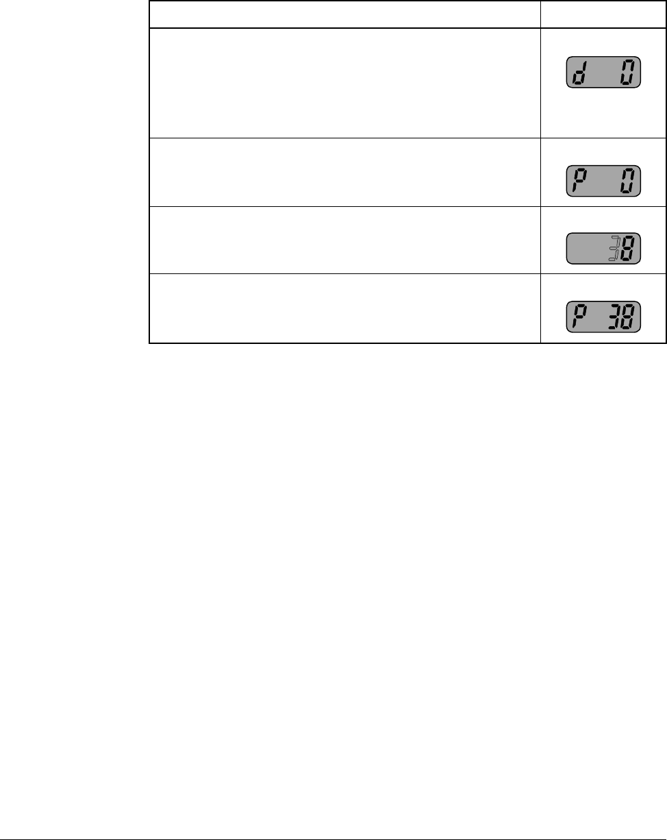
Table 6.6 – Using the Jump Code
Procedure Sample Display
Step 1. From the operation mode, press and hold down the
ENTER key for at least two seconds to change the
drive to the programming mode. The “PROG” LED
will illuminate indicating that the drive is in
programming mode. The drive will display the first
parameter of the “Display” group.
Step 2. Press the right arrow to change to the “Parameters”
group.
Step 3. Press the ENTER key to edit P0 (Jump Code).
Step 4. Press the UP arrow seven times until the display
indicates an “8”.
Step 5. Press the left arrow one time such that the next digit
is displayed. It will be displayed brighter than the
previous digit.
Step 6. Press the UP arrow three times such that the display
indicates the parameter number.
Step 7. Press the ENTER key to accept the value. The value
will be saved in the Jump Code (P0) for future use
and the desired parameter will immediately be
displayed.
6-8 VS1MD AC Drive User Manual
The following example shows how to use a previously stored Jump Code.
6.8 Modifying the Value of a Parameter
The parameters located in the Display group are read-only and can not be modified.
All other parameters (with a few exceptions) can be modified by the user. Some
parameters are configurable - meaning that the drive must be stopped before the
parameter can be modified, while others are tunable - meaning that the parameter can
be modified while the drive is stopped or running.
Table 6.7 – Using a Previously Stored Jump Code
Procedure Sample Display
Step 1. From the operation mode, press and hold down the
ENTER key for at least two seconds to change the
drive to the programming mode. The “PROG” LED
will illuminate indicating that the drive is in
programming mode. The drive will display the first
parameter of the “Display” group.
Step 2. Press the right arrow to change to the “Parameters”
group.
Step 3. Press the ENTER key to access the Jump Code.
Step 4. Press the ENTER key a second time and the desired
parameter will be displayed.
Using the Keypad 6-9
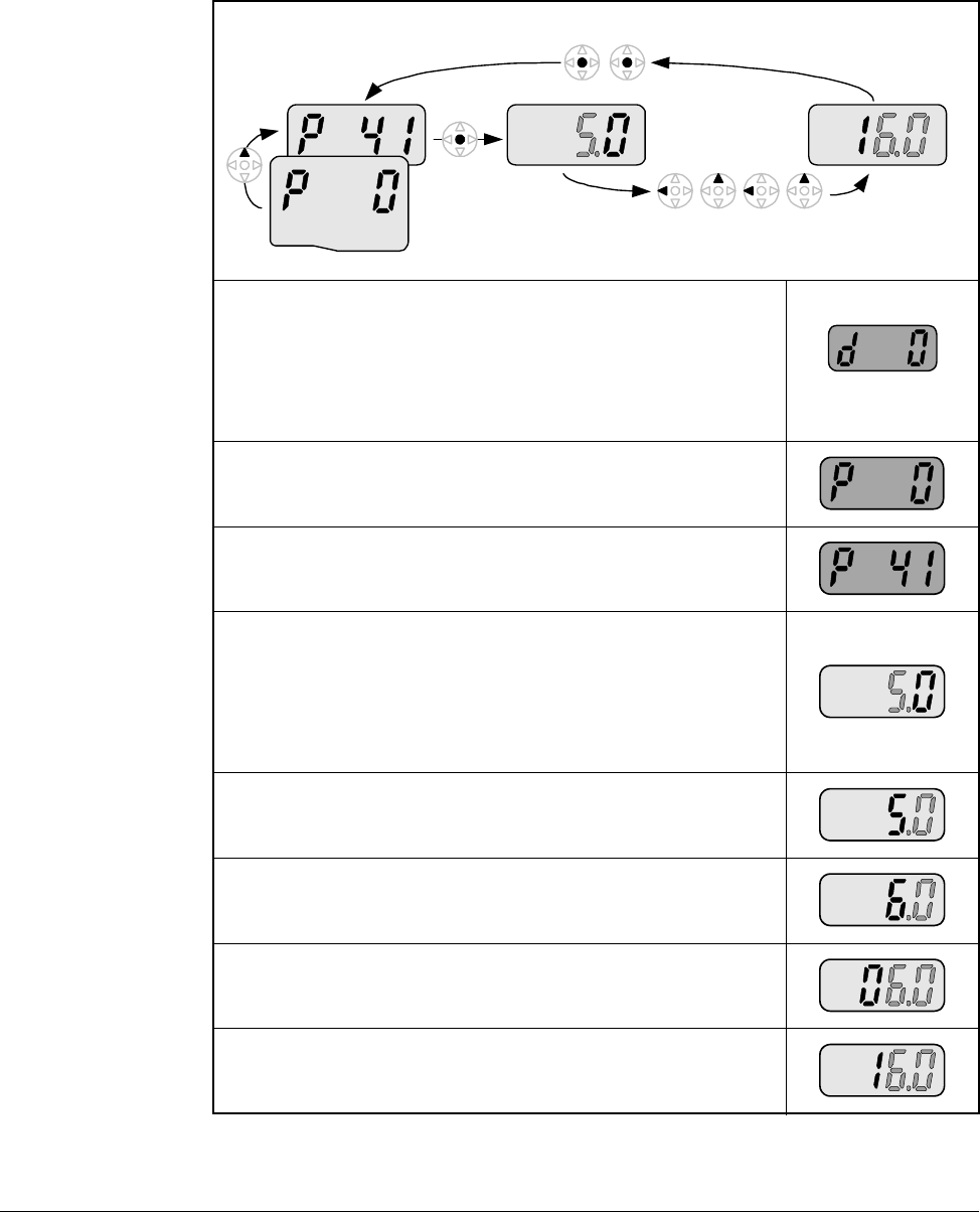
The following example shows how to modify the acceleration time located in
parameter P41.
Table 6.8 – Modifying Parameter Values
Step 1. From the operation mode, press and hold down the
ENTER key for at least two seconds to change the
drive to the programming mode. The “PROG” LED
will illuminate indicating that the drive is in
programming mode. The drive will display the first
parameter of the “Display” group.
Step 2. Press the right arrow key to change to the
“Parameters” group.
Step 3. Use the up arrow or the jump code to display the
acceleration time parameter P41.
Step 4. Momentarily press the ENTER key to begin the
parameter value edit mode. Notice that the tenths
digit is highlighted for editing. At this point you can
use the up arrow key to increment the value all the
way to the new setting (16.0 in this example) or
proceed with the following steps.
Step 5. Press the left arrow key to select the ones digit for
editing.
Step 6. Press the up arrow key to increment the ones digit
from a 5 to a 6.
Step 7. Press the left arrow key to select the tens digit for
editing.
Step 8. Press the up arrow key to increment the tens digit
from a 0 to a 1.
Program Group
6-10 VS1MD AC Drive User Manual
6.9 Monitoring Display Parameters
The Display group is a group that consists of read only values that can be monitored
by the user to diagnose the operation of the drive and motor. To monitor the motor
current, follow the below example.
Step 9. Press the ENTER key to accept the value and the
display will begin to flash so that you can confirm the
entry.
Step 10. Press the ENTER key a second time to acknowledge
the entry. The display will revert to showing the
parameter number.
Table 6.8 – Modifying Parameter Values
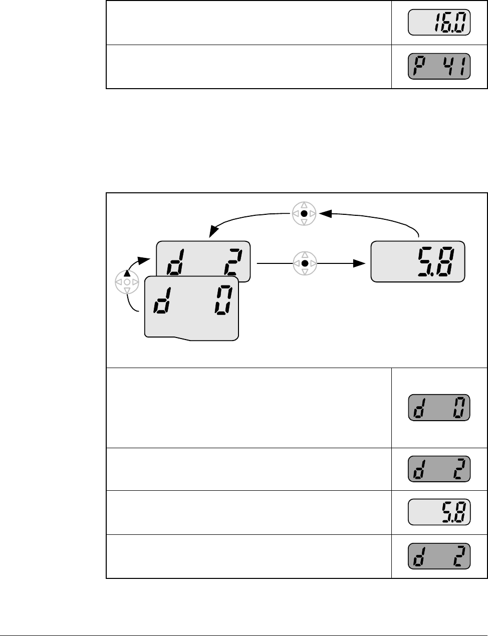
Table 6.9 – Monitoring Display Parameters
Step 1. From the operation mode, press and hold down the
ENTER key for at least 2 seconds to change the
drive to the programming mode. The “PROG” LED
will illuminate indicating that you are in the
programming mode. The drive will display the first
parameter of the “Display” group.
Step 2. Press the up arrow key twice to change to the
parameter d2 (Motor Current).
Step 3. Momentarily press the ENTER key to display the
motor current. The display will be updated in real
time.
Step 4. Press the ENTER key to return to the previous
display so that you can select a new parameter to
view.
Display Group
Using the Keypad 6-11
6.10 Reviewing the Fault Status in the Display Group
When a fault is active, this is annunciated on the drive by flashing the STOP/FAULT
LED. This procedure is used to review the active fault as well as certain conditions at
the time the fault occurred.
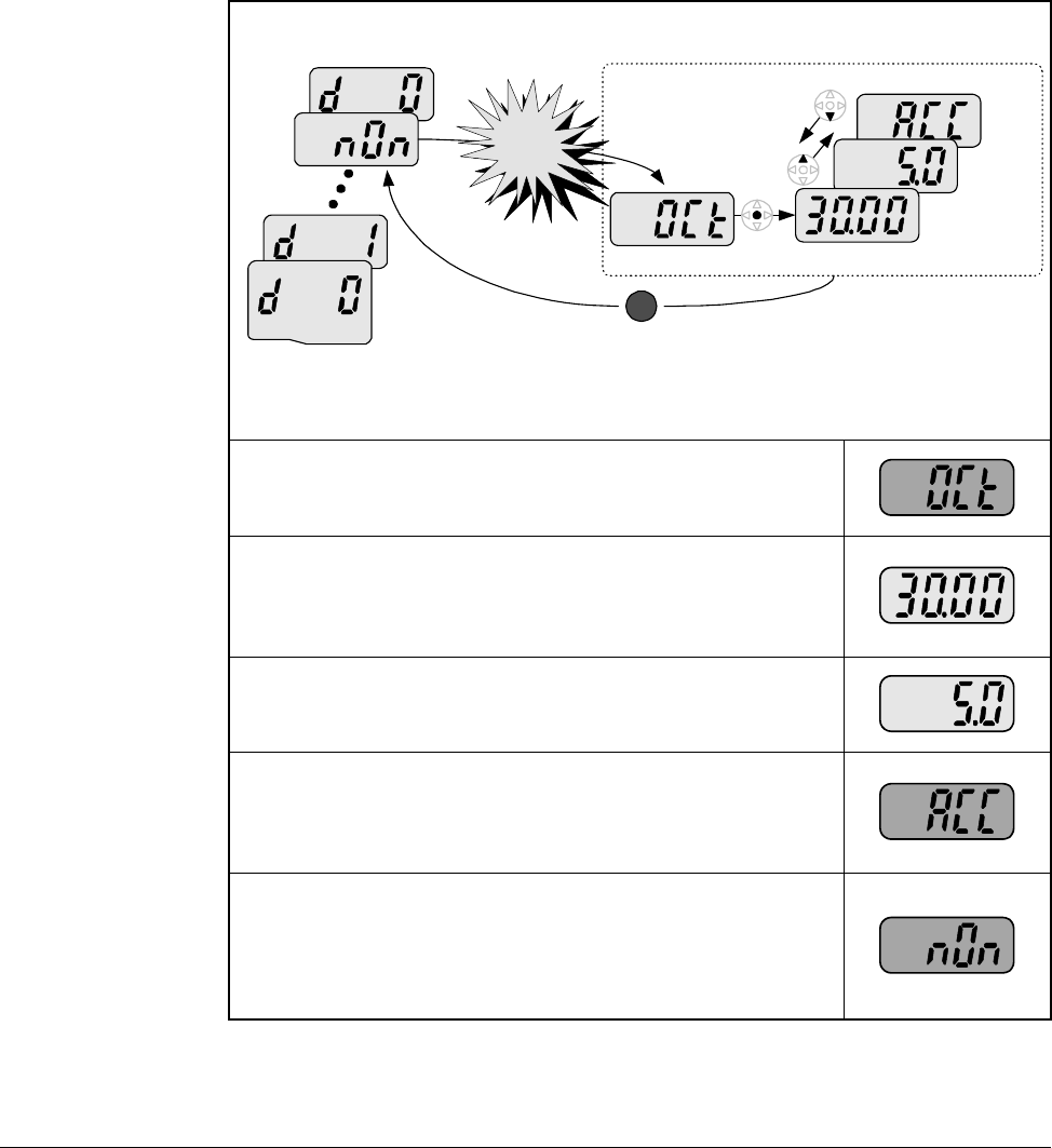
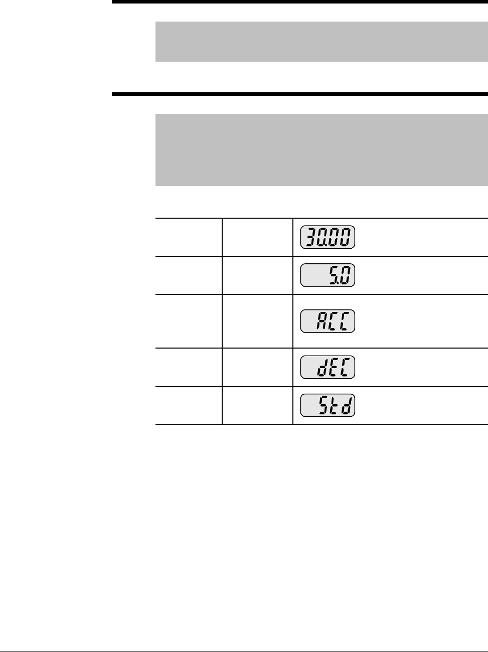
Table 6.10 – Reviewing Fault Status in the Display Group
Step 1. When an overcurrent condition has been detected by
the drive, a fault will be latched and the display will
show the condition.
Step 2. Press the ENTER key to see the frequency at which
the fault occurred. This example indicates that the
drive was outputting 30.00 Hz when the fault
occurred.
Step 3. Press the up arrow to view the output current during
the fault. This example indicates that the drive was
outputting 5.0 Amps when the fault occurred.
Step 4. Press the up arrow key again to view the operating
status of the drive when the fault occurred. This
example indicates that the drive was accelerating
when the fault occurred.
Step 5. Press the STOP/RESET button on the keypad to
reset the fault and the STOP/FAULT LED will
illuminate solid indicating that the fault is cleared and
that the drive is in the stopped condition. The display
will indicate that there is no longer a fault condition.
Frequency
Current
During
Accel
Display Group STOP
RESET
Over-
current
trip
6-12 VS1MD AC Drive User Manual
6.11 Resetting the Parameters to Factory Default
Follow the below procedure to reset the parameters to the factory default values:
Table 6.11 – Resetting Parameters to Factory Default
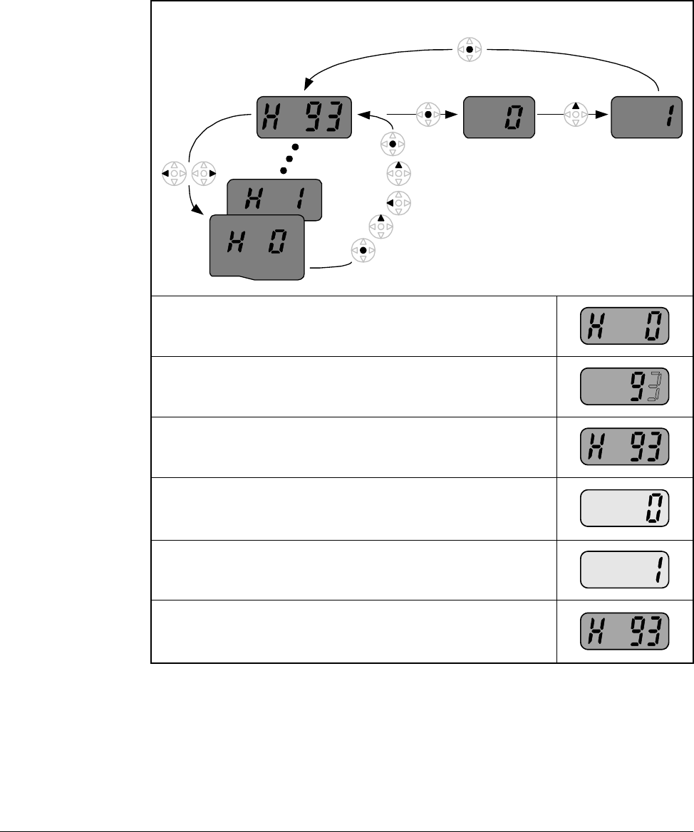
Step 1. Navigate to the Function Group 2 (H Group).
Step 2. Press the ENTER key to edit the jump code. Modify
the jump code to be equal to 93.
Step 3. Press the ENTER key to jump to parameter H93.
Step 4. Press ENTER to display the current value of
parameter H93 (it will be 0 indicating that parameters
will not be reset).
Step 5. Press the up arrow key to change the value to a 1.
Step 6. Press the ENTER key to reset the drive parameters
to factory default. The display will revert back to
displaying the parameter number.
Function Group 2

Parameter Descriptions 7-1
CHAPTER 7
Parameter Descriptions
7.1 Overview
The following information is provided for each parameter listed in table 7.1 along with
its description:
The parameters are presented in numerical order within each of the fivegroups
(Dispay, Basic Parameters, Terminal, Function Group 1, Function Group 2). Appendix
B contains a list of parameters by name cross-referenced to parameter number.
Parameter Number: Unique number assigned to each parameter.
Parameter Name: Unique name assigned to each parameter.
LED Display: Display shown on LED screen when parameter is
accessed.
Range: Predefined parameter limits or selections. Note that
a negative Hz value indicates reverse rotation.
Default: Factory default setting.
Access: •Read Only: Parameter value can not be modified
by user.
•Configurable: Parameter can only be modified
while drive is stopped.
•Tunable: Parameter can be modified while drive
is running or stopped.
Group: Menu group within which parameter is located.
See also: Associated parameters that may provide additional
or related information.

7-2 VS1MD AC Drive User Manual
7.2 Display Group Parameters
Parameters in this group are display only and can be used to monitor drive
conditions. To change the active display for the drive, use parameter H72 - Power
On Display.
d0 Frequency Command
Range: 0.0 to Frequency High Limit (P36) [Hz]
Default: Read Only
Displays the value of the active frequency command. The commanded
frequency is displayed even if the drive is not running.
d1 Motor RPM
Range: 0.0 Motor RPM (based on P33 Motor
Poles) [RPM]
Default: Read Only
Displays the output motor RPM. Motor RPM is scaled based on output
frequency present on terminals U, V and W based on the setting in P33
– Motor Poles.
d2 Output Current
Range: 0.0 to Motor Rated Current (P32) [Amps]
Default: Read Only
Displays the value of the output current present at terminals U, V and W.
d3 Output Voltage
Range: 0.0 to Drive Rated Voltage [volts]
Default: Read Only
Displays output voltage present at U, V, W.
d4 Output Power
Range: 0.0 to (Drive Rated Power x 2) [kW]
Default: Read Only
Displays the value of the output power present at terminals U, V and W.
Parameter Descriptions 7-3
d5 Output Torque
Range: 0.0 to (Drive Rated Torque x 2) [kgf / M]
Default: Read Only
See Also: H36
Displays the value of the output torque present at terminals U, V and W.
Enter motor efficiency indicated on motor nameplate to H36 to display
correct torque.
d6 DC Link Voltage
Range: Based on Drive Rating [Volts DC]
Default: Read Only
Displays the present DC bus voltage level.
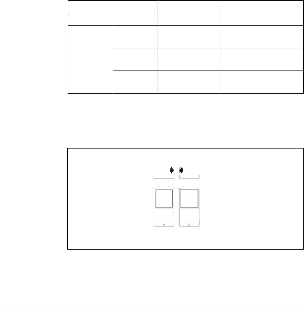
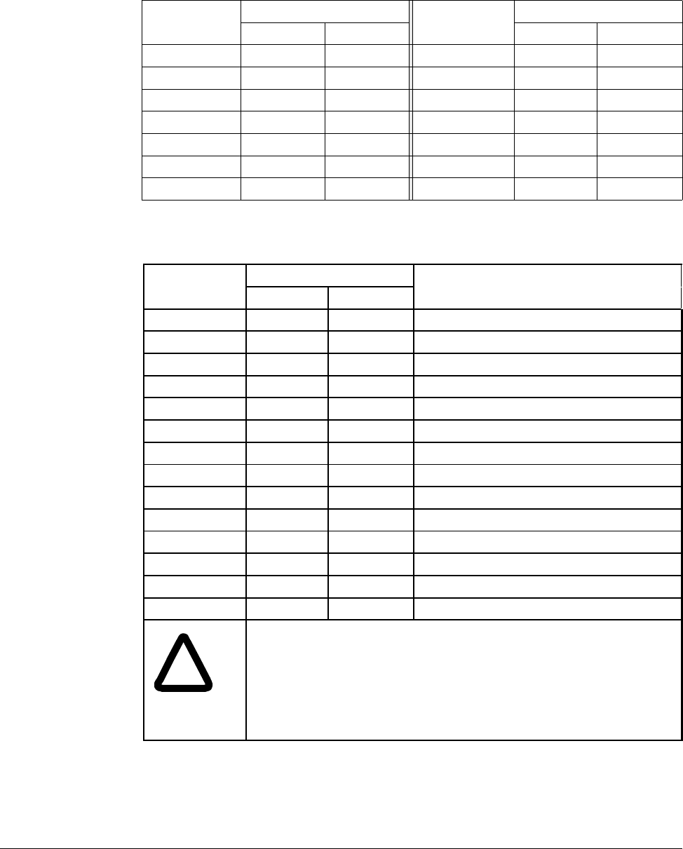
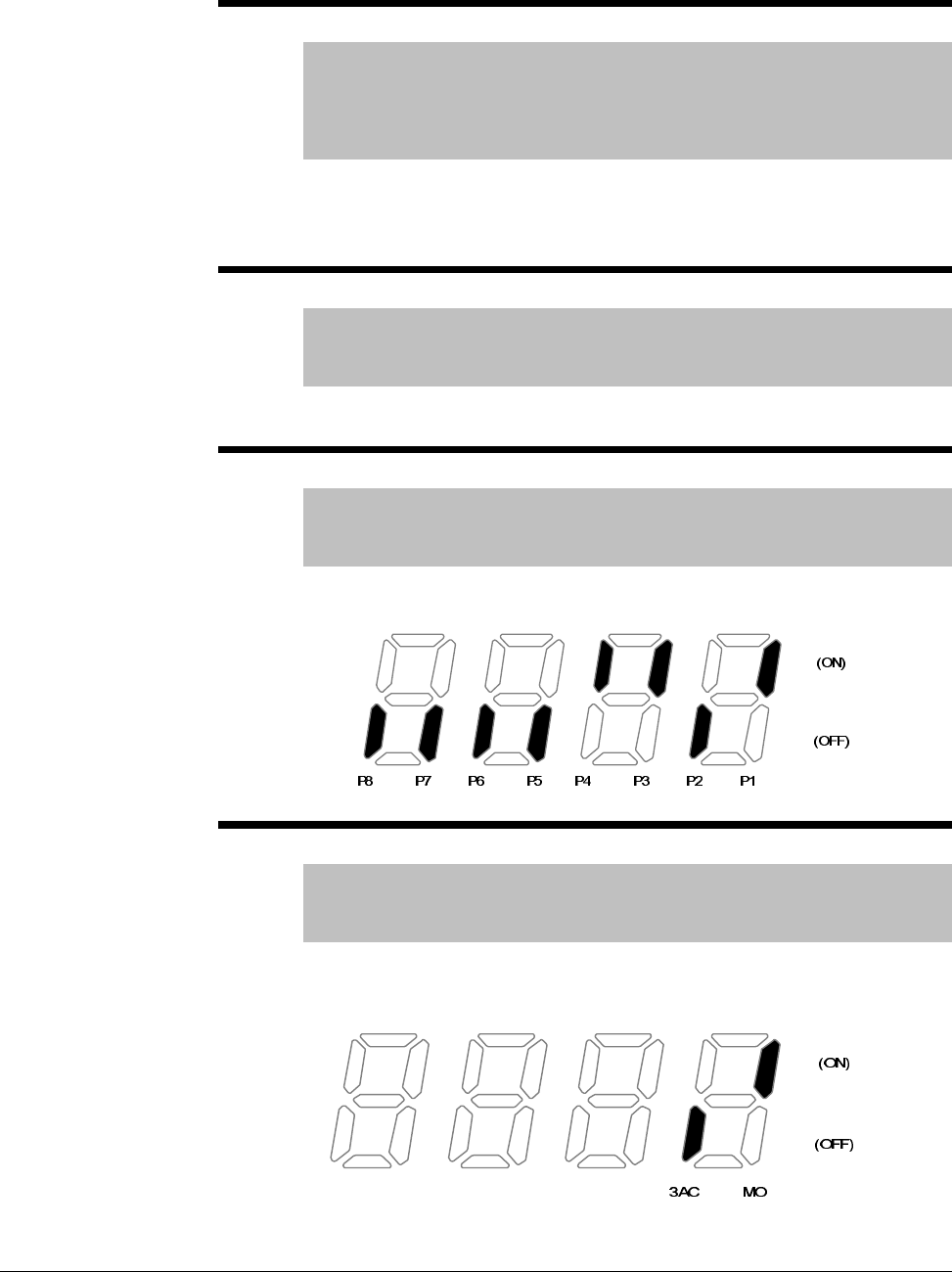
d7 Input Terminal status display
Range: See Figure Below
Default: Read Only
Displays the status of the input terminals P1~P8. An example is
shown below for when P1, P3, P4 are ON and P2, P5 are OFF.
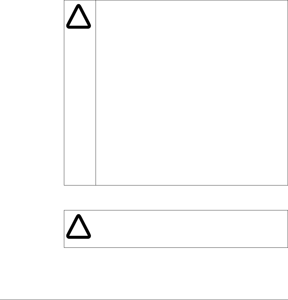
d8 Output terminal status display
Range: See Figure Below
Default: Read Only
Displays the status of the Digital (MO) Output and the Relay
(3A~C) terminals. The following example is for when Digital
Output (MO) is ON and the Relay is OFF.
7-4 VS1MD AC Drive User Manual
d9 Software Version
Range: 1.0 to 99.9
Default: Read Only
Displays the Main Control Board software version.
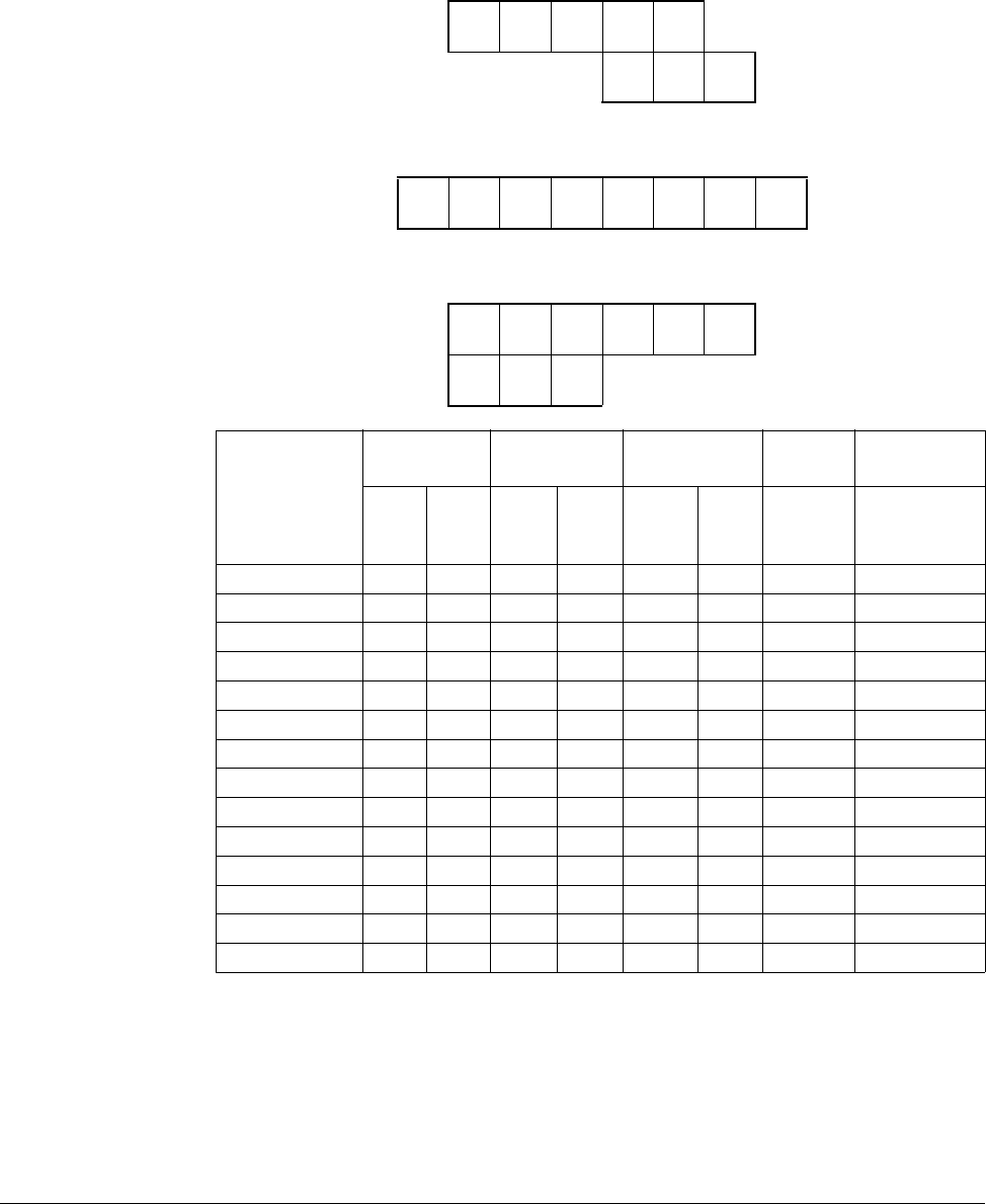
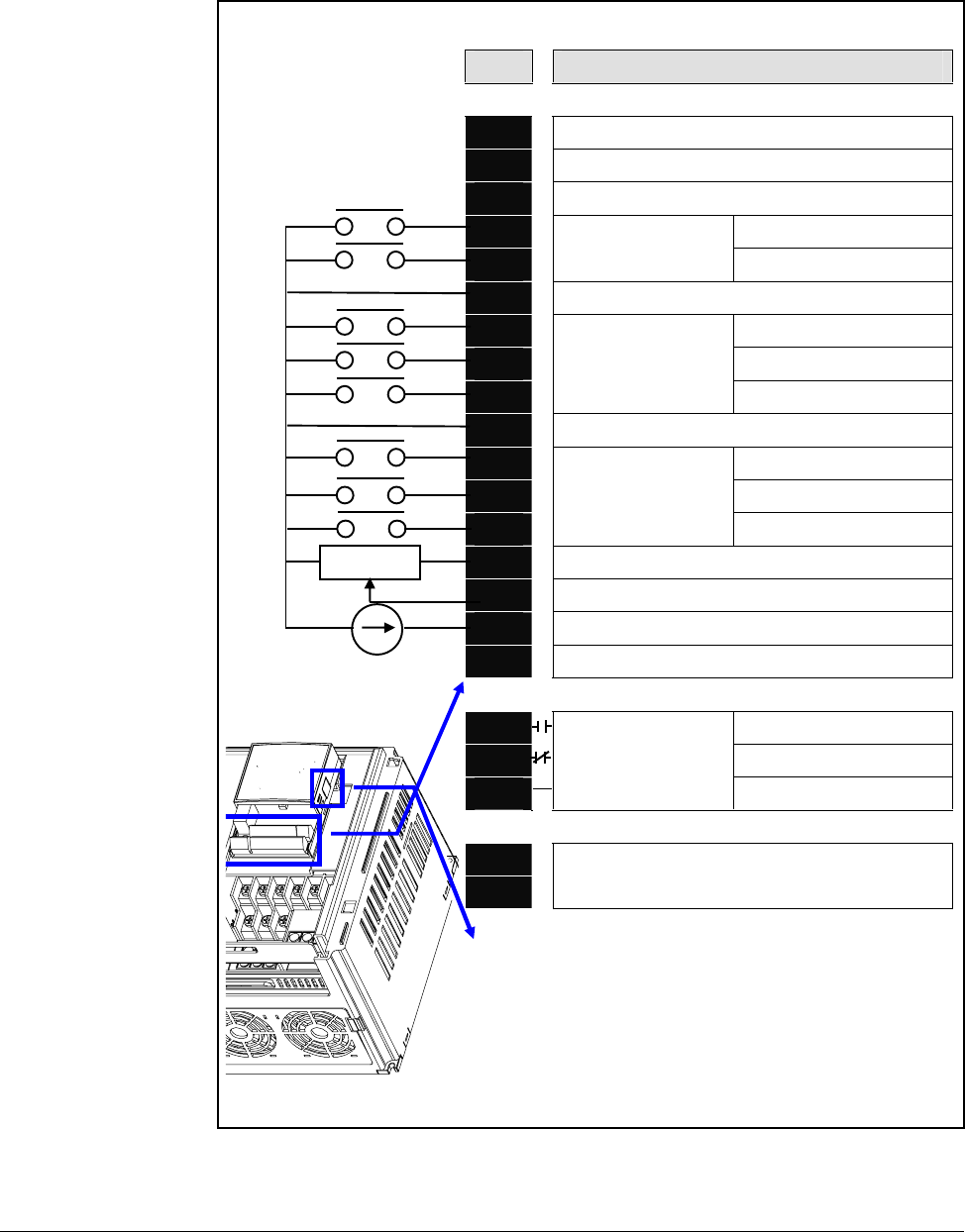
nOn Current Fault Display
Range: See Chapter 9 - Troubleshooting for fault
code description
Default: Read Only
See Also: H1-H6
Displays the types of faults, frequency and operating status at the time of
the last fault.
Fault Types Frequency
Current
Accel/
Decel
Information Fault during Accel
Fault during Decel
Fault during constant run
Fault code history can be viewed in parameters H1 - H5. H6 is used to
clear the fault code history. For a complete description of fault codes,
refer to Chapter 9 - Troubleshooting.

Parameter Descriptions 7-5
7.3 Basic Program Group Parameters
The Basic Program Group (P) contains the parameters most commonly used in
start-up.
Sets the code to jump directly to a specific parameter within the group.
Sets the motor type connected to the drive output side.
P0 Jump Code
Range: 30 -47
Default: 30
Access Tunable
P30 Motor HP Select
Range: 0.5
1
2
3
5
7.5
10
= 0.5 HP
= 1 HP
= 2 HP
= 3 HP
= 5 HP
= 7.5 HP
= 10 HP
Default: Preset based on drive rating.
Access Configurable
See also: P32 - P34
P32 Motor Rated Current
Range: 0.5 - 50 Amps
Default: Preset based on drive rating
Access Configurable
See Also: P30, P33, P34
Enter motor rated current on the nameplate.
P33 Pole Number
Range: 2, 4, 6, 8, 10, 12
Default: 4
Access Configurable
See Also: P30, P32, P34
Select number of motor poles

7-6 VS1MD AC Drive User Manual
The drive outputs its rated voltage to the motor at this frequency (enter motor
nameplate). See parameter F30 for custom V/Hz settings and V/Hz curve.
Sets drive minimum steady state output frequency.
Sets drive maximum steady state output frequency.
This parameter manually sets the frequency that the drive is commanded to output.
Set the desired frequency and press ENTER/PROG to lock the value into memory. If
the drive is running, it will immediately accelerate or decelerate to this value once
enter is pressed. If the drive is not running, entering a value in P37 will pre-set the
speed to accelerate to after a valid run command.
P34 Base Frequency
Range: 30 - 400 [Hz]
Default: 60
Access Configurable
See Also: P30, P33, F30-F38
P35 Frequency Low Limit
Range: 0 - P36 [Hz]
Default: 10.0
Access Configurable
See Also: P36, F30-F38
P36 Frequency High Limit
Range: 0 - 400 [Hz]
Default: 60.0
Access Configurable
See Also: P35
P37 Frequency Command
Range: 0 - 400 [Hz]
Default: 0.00
Access Tunable
Parameter Descriptions 7-7
P38 Stop/Start Source
Range: 0
1
2
3
= Keypad
= Terminal Mode 1 (2 or 3- wire control for forward/reverse)
= Terminal Mode 2 (2 wire with direction switch)
= RS485 Communication
Default: 0 {Local OIM)
Access Configurable
See Also: P40; t1 - t8
Sets the control used to start the drive.
0 Keypad Drive control for start, stop, forward and reverse are from
drive keypad.
1Terminal
Operation Drive is controlled from run forward terminal and run
reverse terminal.
2 Drive is controlled from run terminal and directional
terminal.
3 RS485
Communication Drive operation controlled using RS-485 communications
(see Appendix E).
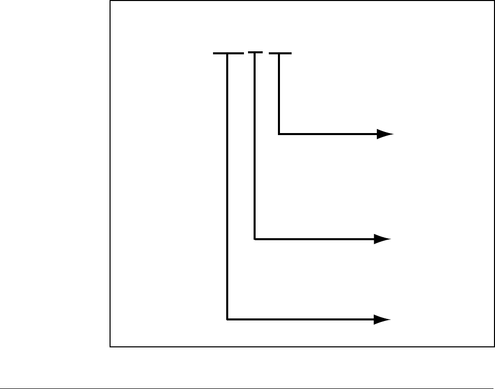
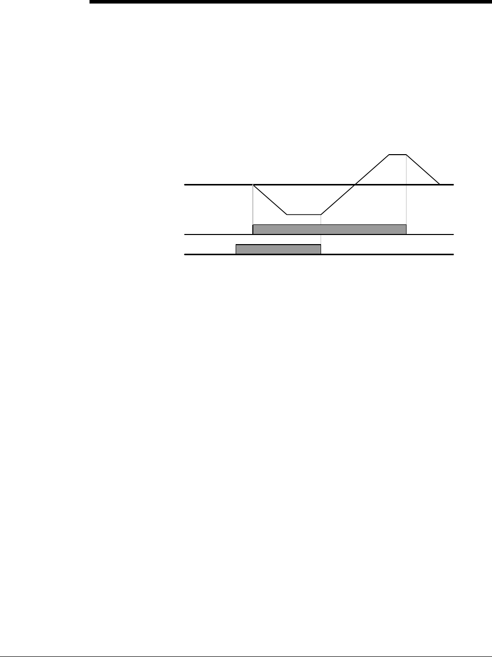
Terminal Operation Mode 1: (2-Wire or 3-Wire Control Fwd/Rev):
•Select one digital input (t1~t8) = 0, run forward (FX).
•Select one digital input (t1~t8) = 1, run reverse (RX).
•To enable 3-Wire control select one digital input (t1~t8) = 17, 3-wire
operation.
•Drive stops when both inputs are off or when both inputs are on.
Forward
Digital In
(FX)
Reverse Digital In (RX)
Drive Output
7-8 VS1MD AC Drive User Manual
Terminal Operation Mode 2: (2-Wire Control with Fwd/Rev Switch):
•Select one digital input (t1~t8) = 0, run forward (FX). Operates as a Run
Command
•Select one digital input (t1~t8) = 1, run reverse (RX). Operates as a
Direction Switch
•To enable 3-Wire control select one digital input (t1~t8) = 17, 3-wire
operation.
•Drive stops when both inputs are off or when both inputs are on.
P38 Stop/Start Source
Run Digital
In (FX)
(RX)
Dive Output
Direction Digital In (RX)
Parameter Descriptions 7-9
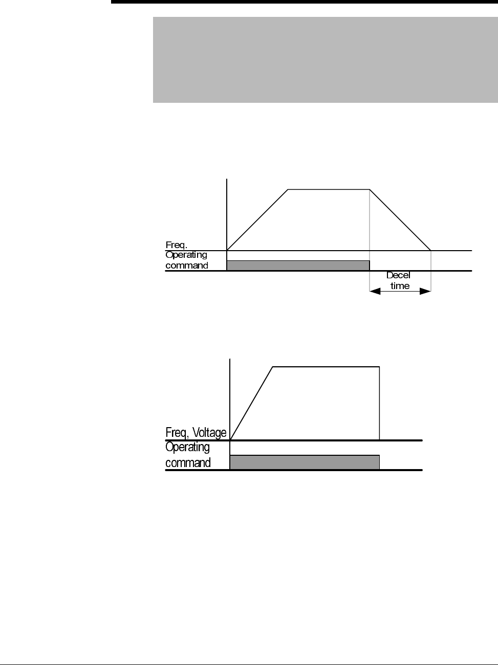
P39 Stop Type
Range: 0
1
2
= Decelerate to Stop (Ramp)
= DC Brake to Stop
= Coast to Stop
Default: 0
Access Configurable
See Also: P38, P42, F8-F11
Sets the active mode for all stop sources.
0 = Decelerate to Stop. Motor decelerates to 0 Hz and stops during the set
time.
1 = DC Brake to stop. See parameters F8 - F11 for further details.
2 = Coast to stop. Output frequency and voltage are shut down on a stop
command

7-10 VS1MD AC Drive User Manual
P40 Frequency Setting Method
Range: 1
2
3
4
5
6
7
= Digital Keypad
= Analog V1 1: -10 - +10V
= Analog V1 2: 0 ~ +10 V
= Analog Terminal I: 0 - 20mA
= Analog Terminal V1 Mode 1+ Terminal I
= Analog Terminal V1 Mode 1+ Terminal I
= Analog RS485
Default: 1
Access Configurable
See Also: t32-t33, F60
Sets the source of the speed reference to the drive.
1 = Keypad:Drive output frequency is set in the operation mode by pressing
the up/down keys. The drive immediately responds to the new setting
without pressing the enter key.
2 = Analog V1 Mode 1:Drive output frequency is set via a +/- 10V signal
applied to analog input terminal V1.
3 = Analog V1 Mode 2:Drive output frequency is set via a 4~20mA signal
applied to analog input terminal V1.
4 = Analog I:Drive output frequency is set via a 4~20mA signal applied to
analog input terminal I.
5 = Analog V1 Mode 1 + I:Drive output frequency is set via the sum of a
+/-10V signal applied to V1 and a 4~20mA signal applied to terminal I.
6 = Analog V1 Mode 2 + I:Drive output frequency is set via the sum of a
0~10V signal applied to V1 and a 4~20mA signal applied to terminal I.
7 = RS485:Drive output frequency is controlled via the RS485
communications port.
P41 Accel Time
P42 Decel Time
Range: 0 - 6,000 [sec]
Default: P41 = 5.0, P42 = 10.0
Access Tunable
See Also: P42, P36, H70, H71
Sets the Accel/Decel time of the drive. When using the multiple accel/decel
curves with preset speeds, this ramp serves as accel/decel time 0.
H71 can be used to scale the accel/decel units and H70 determines if the
time to accel/decel is relative to P35 (Frequency High Limit) or the delta
change of running frequency to set frequency.

Parameter Descriptions 7-11
P43 Preset Speed 1
P44 Preset Speed 2
P45 Preset Speed 3
Range: 0 - 400 [Hz]
Default: P43 = 10, P44 = 20, P45 = 30
Access Tunable
See Also: t1-t8, t10-t13
Provides an internal fixed speed command selectable by digital inputs.
P46 Drive Start/Stop Source 2
Range: 0 - 3 (see table for P38)
Default: 1 = Terminal Mode 1
Access Configurable
See Also: P38, t1-t8
Note: Only viewable when one of the t1-t8 terminals is set
for 22 and P38 = 3 (RS485 Communications).
When RS485 communications is used as the primary mode of controlling
the drive, this parameter serves as an alternate mode. It is selectable by a
digital input (t1-t8) = “22”.
P47 Frequency Setting Mode 2
Range: 1-7 (see table for P40)
Default: 1 = Keypad
Access Configurable
See Also: P40, P47, t1-t8
Note: Only viewable when one of the t1-t8 terminals is set
for 22 and P40 = 7 (RS485 Communications).
When RS485 communications is used as the primary mode of controlling
the drive, this parameter serves as an alternate mode. It is selectable by a
digital input (t1-t8) = “22”.

7-12 VS1MD AC Drive User Manual
7.4 Terminal Parameters
t0 Jump Code
Range: 0 - 81
Default: 0
Access Tunable
Sets the code to jump directly to a specfic parameter within the group.
t1 Digital Input 1 define (I/O Terminal P1)
t2 Digital Input 2 define (I/O Terminal P2)
t3 Digital Input 3 define (I/O Terminal P3)
t4 Digital Input 4 define (I/O Terminal P4)
t5 Digital Input 5 define (I/O Terminal P5)
t6 Digital Input 6 define (I/O Terminal P6)
t7 Digital Input 7 define (I/O Terminal P7)
t8 Digital Input 8 define (I/O Terminal P8)
Range: 0 =Forward Run Command
1 = Reverse Run Command
2 = Emergency Stop Trip
3 = Reset when a Fault occurs (RST)
4 = Jog Operation Command (2-wire only)
5 = Preset Speed Input - Bit 1
6 = Preset Speed Input - Bit 2
7 = Preset Speed Input - Bit 3
8 = Preset Speed Ramp - Bit 1
9 = Preset Speed Ramp - Bit 2
10 = Preset Speed Ramp - Bit 3
11 = DC Brake during start
12 = 2nd Motor Select
13 = Reserved
14 = Reserved
15 = Frequency increase (UP) Command
16 = Frequency decrease (DOWN) Command
17 = 3-wire operation
18 = External Trip: A Contact (EtA)
19 = External Trip: B Contact (EtB)
20 = Self-Diagnostic Function
21 = Exchange between PID operation and V/F operation
22 = Exchange between option (RS485) and Drive
23 = Analog Hold
24 = Accel/Decel Disable
25 = Up/Down Save Freq. Initialization
Default: t1=0, t2=1, t3=2, t4=3, t5=4, t6=5, t7=6, t8=7
Access Tunable
Selects the function for the digital inputs.
Parameter Descriptions 7-13
0 = Forward Run (FX) Command: Select to define a digital input as a
forward run command in 2-wire or 3-wire control. For both 2-wire and
3-wire control, P38 – Drive Mode should be set to a 1 for normal operation.
For 3-wire control an additional terminal must be defined as 17 = 3-wire
operation.
1 = Reverse Run (RX) Command: Select to define a digital input as a
reverse run command in 2-wire or 3-wire control. For both 2-wire and
3-wire control, P38 – Drive Mode should be set to a 1 for normal operation.
For 3-wire control an additional terminal must be defined as 17 = 3-wire
operation.
2 = Emergency Stop (BX) Trip: Defines a digital input as a stop command.
Drive will stop according to P39 = Stop mode select (ramp deceleration, dc
brake or coast to rest).
3 = Fault Reset (RST): When input is present, clears an active fault and
resets the drive.
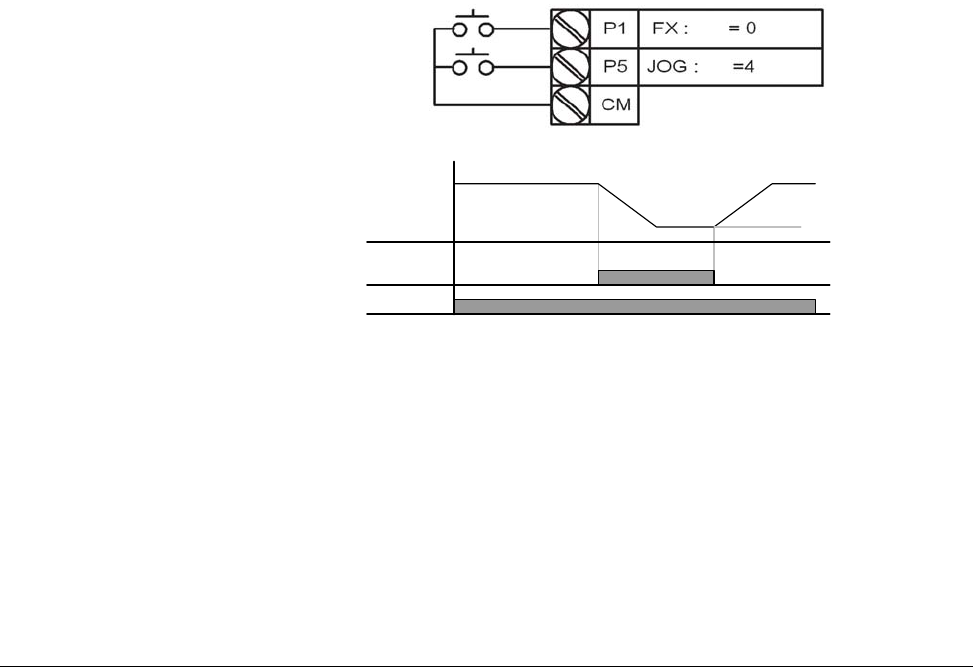
4 = Jog: When input is present, the drive ramps to the value set in Jog
Frequency (F20). Jog operation overrides all other operations except Dwell
operation. Therefore, if Jog frequency command is entered in the middle of
Preset Speed, Up-Down or 2-wire control; operation is executed at jog
frequency. A valid start command is required separate from the dedicated
jog input. The jog function is only available for 2-wire control.
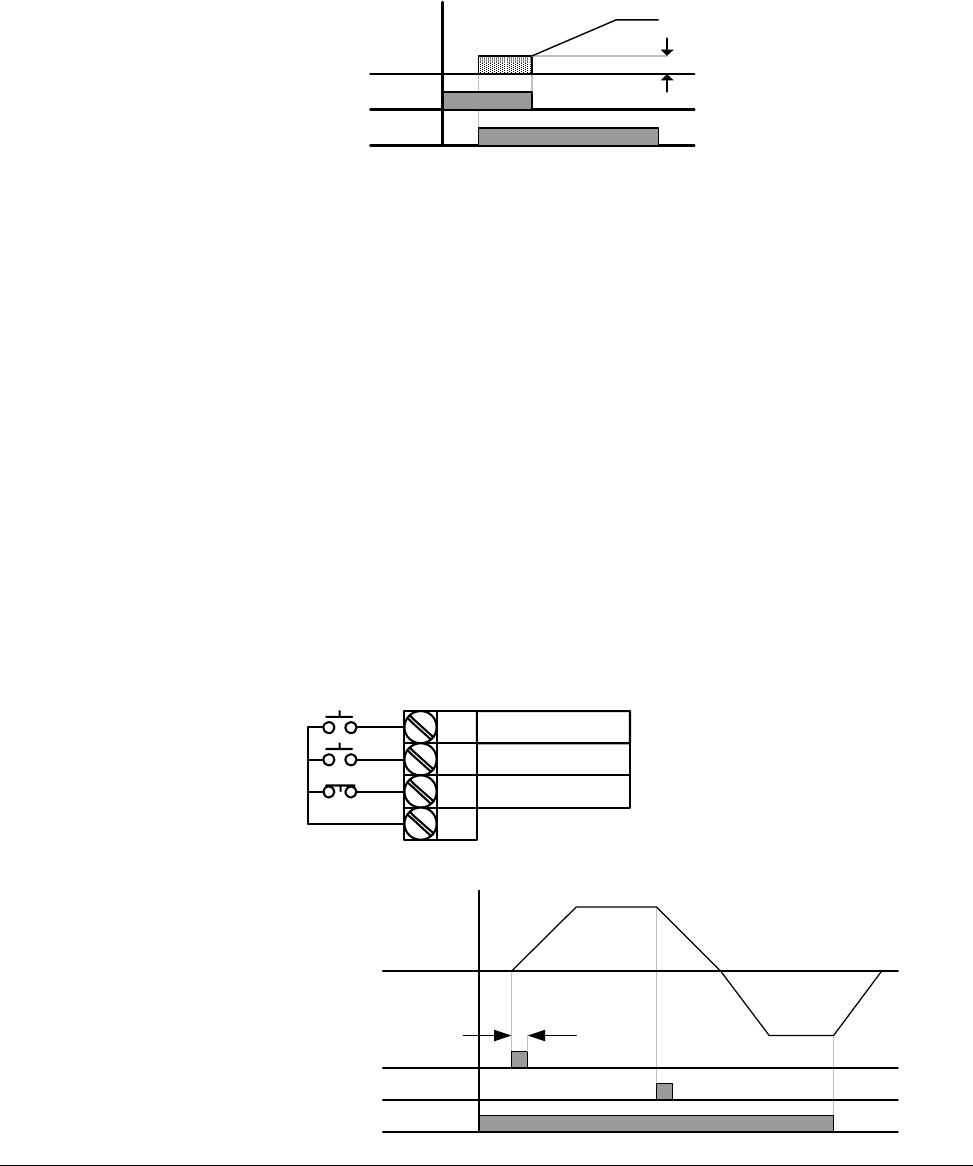
5 = Preset Speed Input – Bit 1
6 = Preset Speed Input – Bit 2
7 = Preset Speed Input – Bit 3:
Used to select Preset Speed 1 ~ 7 combinations, see preset speed
frequencies P43~P45 and t10~t13.
8 = Preset Speed Ramp – Bit 1
9 = Preset Speed Ramp – Bit 2
10 = Preset Speed Ramp – Bit 3:
Used to define accel/decel ramp combinations for preset speeds, see
(t14~t27).
t1
t5
P5 (JOG)
Run
command(FX)
Frequency F20
7-14 VS1MD AC Drive User Manual
11 = DC brake during start: DC voltage will be applied to the motor
windings at a level set by DC Brake Start Voltage (F12) for as long as the
digital input is closed. See also F12 and F13 – Starting DC brake
parameters.
12 = 2nd motor select: When input is present, the drive configures itself for
a second set of motor settings defined in 2nd motor operation parameters
(H81 to H90).
13 = Reserved: Reserved
14 = Reserved: Reserved
15 = Frequency increase (UP): Increases the frequency reference to the
drive after a run command. Frequency is saved to parameter F64 on a stop
command if F63 = 1 ‘save up/down frequency’.
16 = Frequency decrease (DOWN): decreases the frequency reference to
the drive after a run command. Frequency is saved to parameter F64 on a
stop command if F63 = 1 ‘save up/down frequency’.
17 = 3-wire operation: Select to define a digital input for 3-wire control.
Inputs defined as forward (FX) and reverse (RX) are momentary inputs and
opening the input defined as 3-wire operation will stop the drive. For both
2-wire and 3-wire control, P38 – Drive Mode should be set to a 1 for normal
operation.
Voltage
Run
command
F12
P3
P1
P2
P8
CM
FX : t1 = 0
RX : t2 = 1
3-Wire : t8 = 17
FX
RX
Frequency
P8 (3-Wire)
t
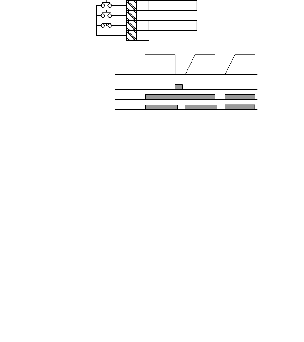
Parameter Descriptions 7-15
18 = External trip – A (N.O.): Normally open contact input. When a digital
input is set to “Ext trip-A” is ON (Closed), the drive displays the fault and
turns off its output power.
19 = External trip – B (N.C.): Normally closed contact input. When a digital
input is set to “Ext trip-B” is OFF (Open), the drive displays the fault and
turns off its output power.
20 = Self-Diagnostic function: Defines a digital input to initiate the
self-diagnostic function capability of the drive unit. Parameter H60 =
Self-Diagnostic function is used to define the test to conduct; IGBT fault and
ground fault, Output phase short/open circuit/ground fault or ground fault
(IGBT fault/output phase short/open circuit). See Chapter 8 – Customizing
Your Application for advanced drive function description.
21 = Change from PID to V/Hz Operation: Selects a digital input to bypass
the PID Feedback controller and selects the default V/Hz control settings.
See Chapter 8 – Customizing your application for advanced drive function.
22 = Change from Option (RS485) to Inverter: When the defined input is
turned ON, setting values in drv2 and Frq2 are used for control and
reference to the drive. This function is only available when the P38 = Drive
mode is programmed for 3 = RS485. Settings for drv2 and Frq2 can not be
changed while the digital input is closed.
P1
P7
P8
FX : t1 = 0
N.O. : t2 = 18
CM
N.C. : t8 = 19
P4(A contact)
Frequency
Run
command
P5(B contact)
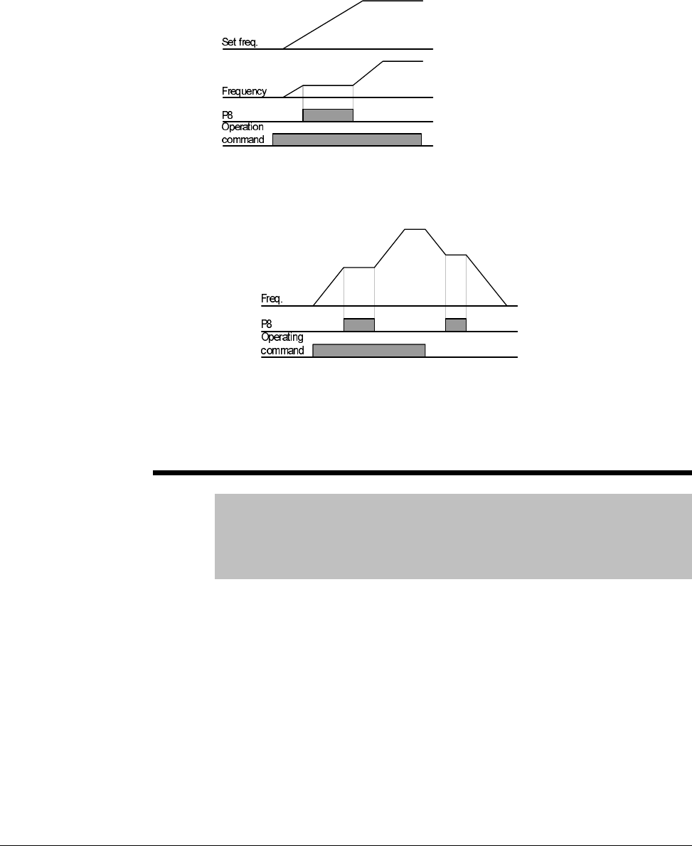
7-16 VS1MD AC Drive User Manual
23 = Analog Hold: Locks the analog speed reference at the last value
when the input was closed. Available when P40 = Frequency setting
method is set in the range of 2 ~ 7.
24 = Accel/Decel Disable: Disables the acceleration or deceleration ramp
while the digital input is closed, holding the reference at its last value.
25 = Up/Down Frequency Save Initialization: When the digital input is
active, the last Up/Down frequency is saved. Useable when digital inputs
are configured as 15 = Frequency Increase (UP) and 16 = Frequency
Decrease (DOWN).
t9 Filtering Time Constant for Multi-function input terminal
Range: 1 - 15
Default: 4
Access Tunable
See Also: t1-t8
The higher the value is set, the slower the responsiveness of the digital
input becomes.
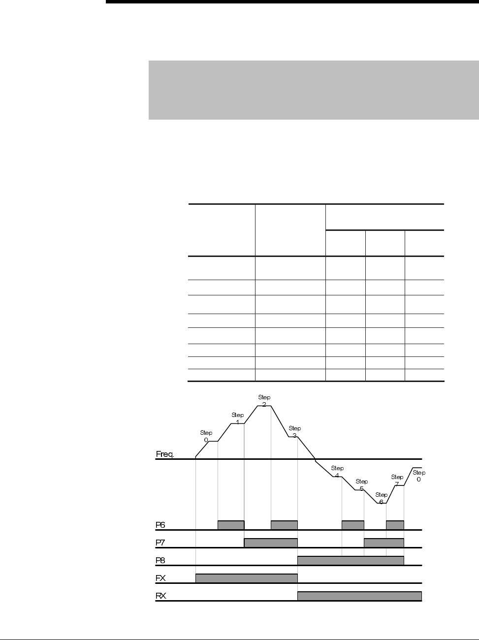
Parameter Descriptions 7-17
t10 Preset Speed 4
t11 Preset Speed 5
t12 Preset Speed 6
t13 Preset Speed 7
Range: 0-400 [Hz]
Default: t10 =30, t11=25, t12=20, t13=15
Access Tunable
See Also: t1-t8, P43-P45
Provides a fixed frequency command value when Digital Input 1 ~ 8 is set
for a Preset Speed (Option 5, 6 and 7). Closing a digital input programmed
as a preset speed will cause the drive to operate at the defined speed.
Preset speeds 1~3 are set in the basic parameter group (P43~P45) while
preset speeds 4~7 are set in the terminal group (t30~t33).
Preset Speed Input
Parameter
Preset Speed
Bit 3
Bit 2
Bit 1
P40
Freq
Command
-
-
-
P43
1
-
-
P44
2
-
-
P45
3
-
t30
4
-
-
t31
5
-
t32
6
-
t33
7

7-18 VS1MD AC Drive User Manual
t14 Preset Speed Accel Time 1
t15 Preset Speed Decel Time 1
t16 Preset SpeedAccel Time 2
t17 Preset Speed Decel Time 2
t18 Preset Speed Accel Time 3
t19 Preset Speed Decel Time 3
t20 Preset Speed Accel Time 4
t21 Preset Speed Decel Time 4
t22 Preset Speed Accel Time 5
t23 Preset Speed Decel Time 5
t24 Preset Speed Accel Time 6
t25 Preset Speed Decel Time 6
t26 Preset Speed Accel Time 7
t27 Preset Speed Decel Time 7
Range: 0 - 6000 [Sec]
Default: t14, t15 = 3.0; t16, t17 = 4.0; t18, t19 = 5.0; t20, t21 = 6.0;
t22, t23 = 7.0, t24, t25 = 8.0, t26, t27 = 9.0
Access Tunable
See Also: t1-t8, t10-t13, P43-P45
Sets multiple acceleration and deceleration ramps based on a digital input
closure.
Preset Speed
Ramp
No.
Accel/
Decel
Time
Bit 3
Bit 2
Bit 1
P41
P42
0
-
-
-
t14
t15
1
-
-
t16
t17
2
-
-
t18
t19
3
-
t20
t21
4
-
-
t22
t23
5
-
t24
t25
6
-
t26
t27
7
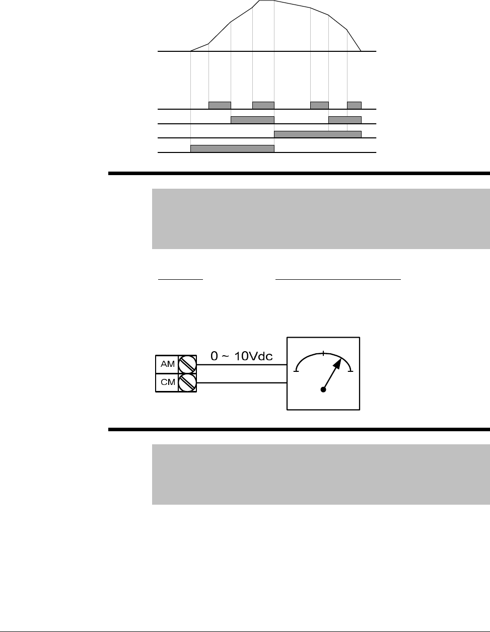
Parameter Descriptions 7-19
t28 Analog Output Select
Range: 0 - 3
Default: 0
Access Tunable
See Also: t29
Selects the value to send to the analog output terminals.
t29 Analog Output Level Adjustment
Range: 10 - 200%
Default: 100
Access Tunable
See Also: t28
Adjusts the scaling of the analog output based on a 10V signal.
Frequency
P3
P4
P5
FX
Accel
Time 0
Accel
time 1
Accel
time 2
Accel
time 3
Decel
time 4 Decel
time 5 Decel
time 6
Decel
time 7
Setting: 10V Output Proportional To:
0 = Output Frequency P36 – Frequency High Limit
1 = Output Current 150% of Inverter rated current
2 = Output Voltage 282Vac or 564Vac (200V or 400V Drive Rating
)
3 = DC Link Voltage 400Vdc or 800Vdc (200V or 400V Drive Rating
)

7-20 VS1MD AC Drive User Manual
t30 Frequency detection level
t31 Frequency detection bandwidth
Range: 0-400 [Hz]
Default: t30 = 30, t31 = 10
Access Tunable
See also: t32-t33
Used when t32 or t33 are set to 0-4, can not be set higher than P36
(Frequency High Limit). See Chapter 8 - Customizing Your Application for
more information.
t32 Digital Output (MO)
t33 Relay Output ( 3A - 3C)
Range: 0 = FDT-1
1 = FDT-2
2 = FDT-3
3 = FDT-4
4 = FDT-5
5 = Overload (OLt)
6 = Inverter Overload (LoIT)
7 = Motor Stall STALL
8 = Over voltage trip (OV)
9 = Low voltage trip (LV)
10 = Inverter overheat (OH)
11 = Command Loss
12 = During run
13 = During stop
14 = During constant run
15 = During speed searching
16 = Wait time for run signal input
17 = Fault Output
18 = Cooling Fan Trip Alarm
Default: t32=12, t33=17
Access Tunable
See Also: t34, F54-F55, F59-F60
Sets the on/off point for the Digital and Relay outputs. See Chapter 8 –
Customizing Your Application for details on this parameter.
t34 Fault Relay Output
Range: 0-7
Default: 2
Access Tunable
See Also: t33
Outputs a fault code when t33 – Relay Output is set to 17: Fault Output.
See Chapter 8 – Customizing Your Application for more information on this
parameter.
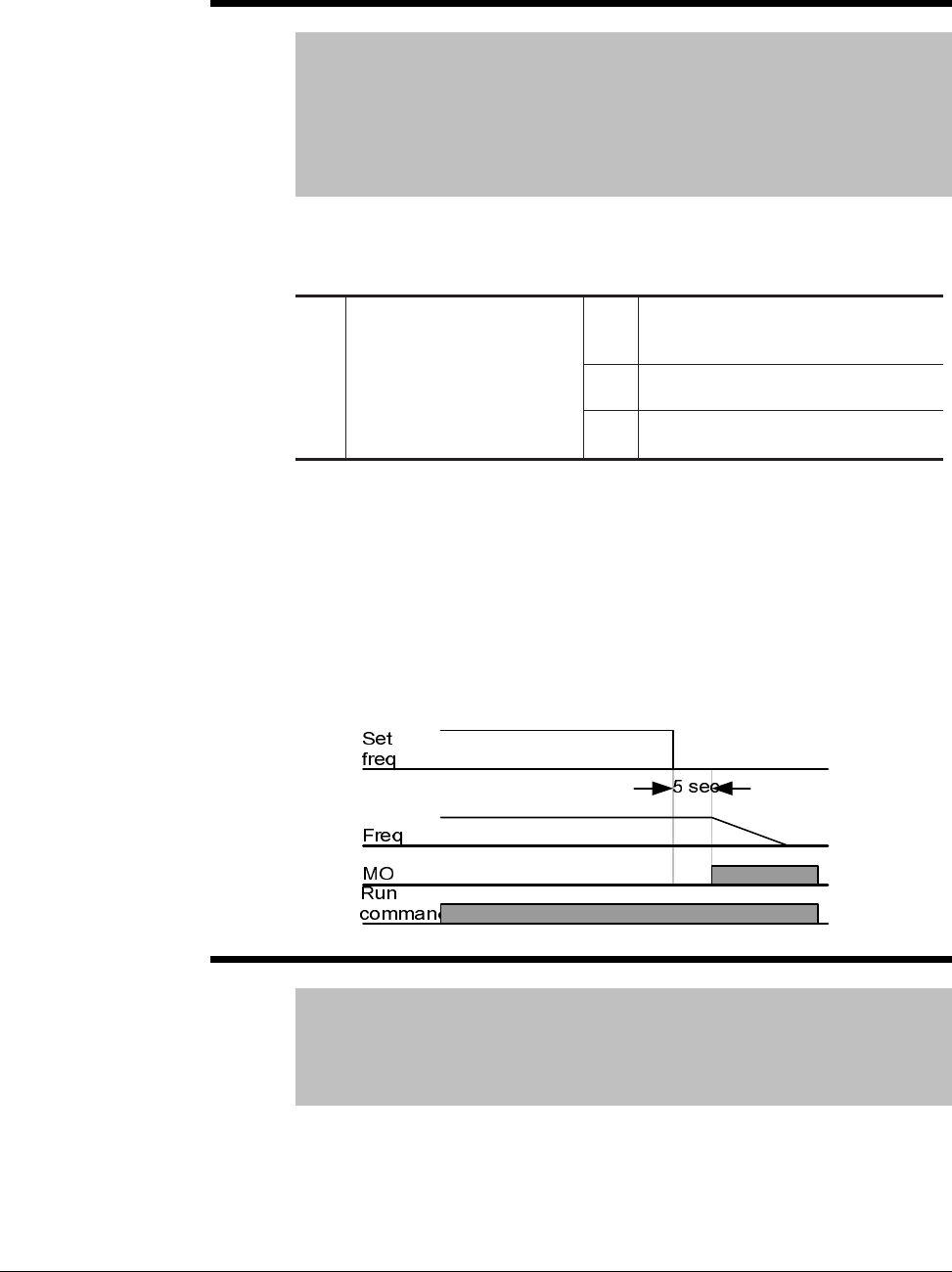
Parameter Descriptions 7-21
t35 Criteria for Analog Input Signal Loss
Range: 0 = Disabled
1 = Activated below half of set value
2 = Activated below set value
Default: 0
Access Tunable
See Also: t32-t33, t36, t41, t46, t62-t63
Selects the drive mode when frequency reference set by the Analog (V1, I)
input terminal or communication option is lost.
Example 1) The inverter determines the freq reference is lost when P40 –
Freq set method is set to 3 (Analog V1 input), t16 to 1 and analog input
signal is less than half the value set in t36.
Example 2)The inverter determines the freq reference is lost when P40 –
Freq set method is set to 6 (V1+I), t16 to 2 and V1 input signal is either
below the value set in t36 or I input value is less than the t46 value.
Example diagram when t35 is set to 2, I62 to 2, I63 to 5.0 sec and t32 to 11:
t36 Analog Input 0 to -10V (NV) Min voltage
Range: 0 to -10V
Default: 0
Access Tunable
See Also: P40, t37
Sets the minimum voltage of the NV (-10 to 0V) input.
0Disabled (Does not check the
analog input signal loss)
1When half the value set in t36,
t41, t46 is entered
t35 [Criteria for analog input
signal loss]
2When less than the value set in
t36, t41, t46 is entered

7-22 VS1MD AC Drive User Manual
t37 Frequency corresponding to t36
Range: 0 - 400 [Hz]
Default: 0
Access Tunable
See Also: t37
Sets the inverter output minimum frequency at minimum voltage of the NV
input.
t38 Analog Input 0 to -10V (NV) Max voltage
Range: 0 - 10V
Default: 10
Access Tunable
See Also: P40, t39
Sets the maximum voltage of the NV input.
t39 Frequency corresponding to t38
Range: 0 - 400 [Hz]
Default: 60
Access Tunable
See Also: t38
Sets the inverter output maximum frequency at maximum voltage of the NV
input.
t40 Analog Input 0 - 10V (V1) Filter time constant
Range: 0 - 9999
Default: 10
Access Tunable
See Also: P40, t41-t43
Adjusts the responsiveness of the Analog (V1) input (0~+10V) to filter noise.
t41 Analog Input 0 - 10V (V1) Min voltage
Range: 0 - 10V
Default: 0
Access Tunable
See Also: t40, t42
Sets the minimum voltage of the Analog Input (V1) input.

Parameter Descriptions 7-23
t42 Frequency corresponding to t41
Range: 0 - 400 [Hz]
Default: 0
Access Tunable
See Also: t41
Sets the inverter output minimum frequency at minimum voltage of the V1
input.
t43 Analog Input 0-10V (V1) Max voltage
Range: 0 - 10V
Default: 10
Access Tunable
See Also: t44
Sets the maximum voltage of the V1 input.
t44 Frequency corresponding to t43
Range: 0 - 400 [Hz]
Default: 60
Access Tunable
See Also: t43
Sets the inverter output maximum frequency at maximum voltage of the V1
input.
t45 Analog Input 0-20mA (I) Filter time constant
Range: 0 - 9999
Default: 10
Access Tunable
See Also: P40, t46-t49
Adjusts the responsiveness of the Analog (I) input (0-20mA) to filter noise.
t46 Analog Input 0-20mA (I) Min Current
Range: 0-20mA
Default: 4
Access Tunable
See Also: t45, t47
Sets the minimum current of the Analog 0-20mA (I) Input.

7-24 VS1MD AC Drive User Manual
t47 Frequency corresponding to t46
Range: 0 - 400 [Hz]
Default: 0
Access Tunable
See Also: t46
Sets the inverter output minimum frequency at minimum current of the I
input.
t48 Analog Input 0-20mA (I) Max Current
Range: 4 - 20mA
Default: 20
Access Tunable
See Also: t47
Sets the maximum current of the Analog 0-20mA (I) Input.
t49 Frequency corresponding to t47
Range: 0 - 400 [Hz]
Default: 60
Access Tunable
See Also: t48
Sets the inverter output maximum frequency at maximum current of the I
input.
t57 Keypad Error Output
Range: 0 - 3
Default: 0
Access Tunable
Selects the Digital and/or Relay output when a keypad-inverter
communication fails.
When communication error occurs for a certain time, will be
displayed and the error signal can be sent to the Digital (MO) or Relay
output.
Relay Output
Bit 2
Digital Output
Bit 0
0-
1-
2
3
-
-
0: Not used 1: Signal output to MO
2: Signal output to 3A, 3B contacts 3: Signal output to MO, 3A, 3B

Parameter Descriptions 7-25
t59 Communication protocol select
Range: 0=Modbus RTU
1=LS BUS
Default: 0
Access Configurable
See Also: t60-t61, t64-t81
Sets the protocol for the serial communication network.
t60 Inverter Number
Range: 1-250
Default: 1
Access Tunable
See Also: t59, t61, t64-t81
Sets the drive node address for the RS485 port multi-drop network.
t61 Baud Rate
Range: 0=1200 [bps]
1=2400 [bps]
2=4800 [bps]
3=9600 [bps]
4=19200 [bps]
Default: 3
Access Tunable
See Also: t59-t60, t64-t81
Selects the Baud Rate of RS485 Communication.
t62 Frequency Loss Mode
Range: 0=Continue operation at last frequency command
1= Coast to Stop.
2= Decelerate to stop.
Default: 0
Access Tunable
See Also: P40, t35, t63
When the frequency reference is from the Analog Input or RS485 Port, this
parameters sets the action to take if the speed reference is lost.

7-26 VS1MD AC Drive User Manual
t63 Frequency Loss Wait Time
Range: 0.1-120 [sec]
Default: 1.0
Access Tunable
See Also: P40, t35, t62
This is the time delay before the drive takes action in the event of a
command frequency loss. If there is no frequency command input during
the time set in this parameter, the drive starts to operate in the mode
selected in t62.
t64 Communication Time Setting
Range: 2-100 [ms]
Default: 5
Access Tunable
See Also: t59-t61, t65-t81
Frame Communication time.
t65 Parity/Stop Bit Setting
Range: 0=Parity: None, Stop Bit: 1
1=Parity: None, Stop Bit: 2
2=Parity: Even, Stop Bit: 1
3=Parity: Odd, Stop Bit: 1
Default: 0
Access Tunable
See Also: t59-t61, t64, t66-t81
When the protocol is set, the communication format can be set.
t66 Read address register 1
t67 Read address register 2
t68 Read address register 3
t69 Read address register 4
t70 Read address register 5
t71 Read address register 6
t72 Read address register 7
t73 Read address register 8
Range: 0-42239
Default: t66=5, t67=6, t68=7, t69=8, t70=9, t71=10, t72=11, t73=12
Access Tunable
The user can register up to 8 discontinuous addresses and read them all
with one read command.

Parameter Descriptions 7-27
t74 Write address register 1
t75 Write address register 2
t76 Write address register 3
t77 Write address register 4
t78 Write address register 5
t79 Write address register 6
t80 Write address register 7
t81 Write address register 8
Range: 0-42239
Default: t74=5, t75=6, t76=7, t77=8, t78=5, t79=6, t80=7, t81=8
Access Tunable
The user can register up to 8 discontinuous addresses and read them all
with one read command.
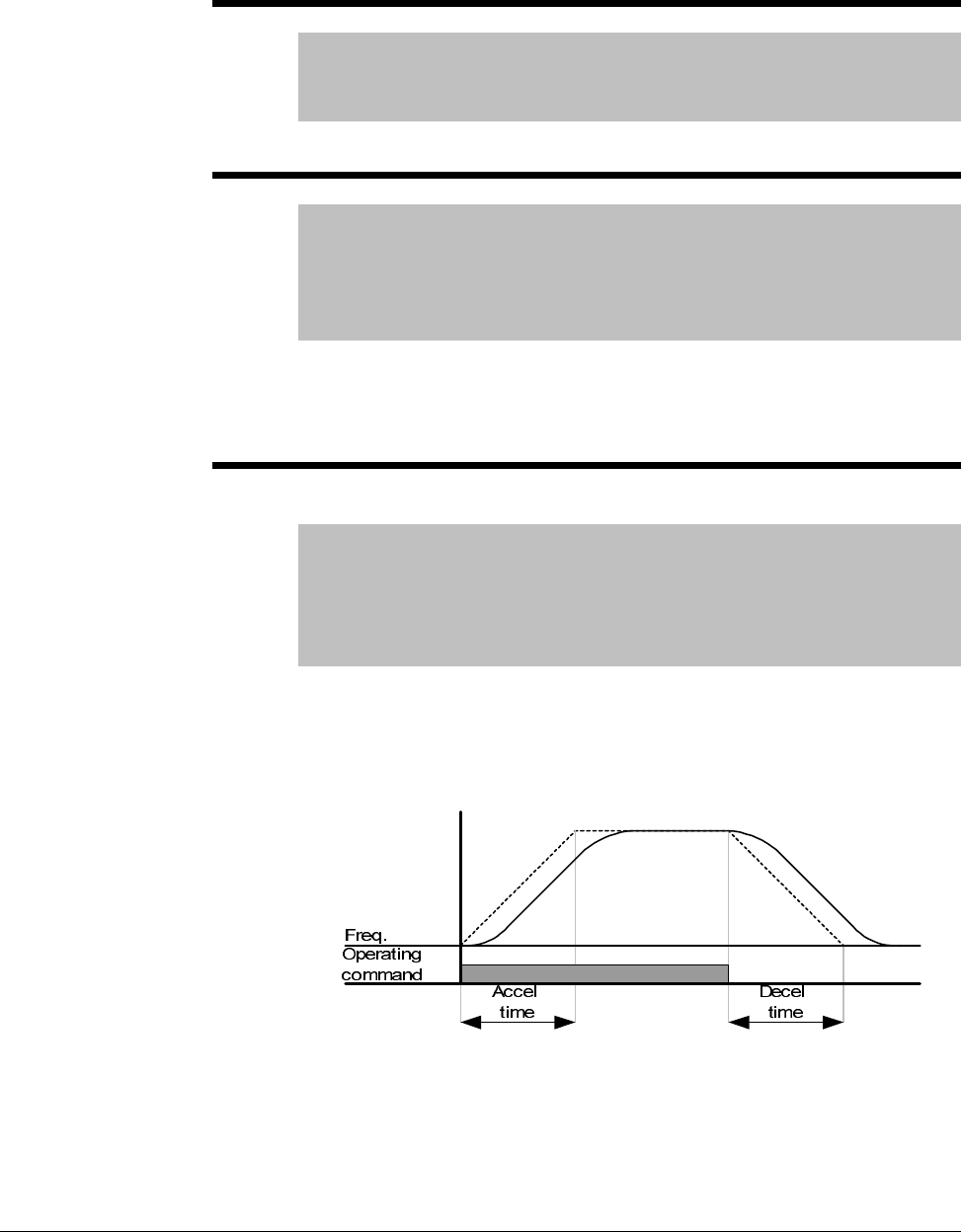
7-28 VS1MD AC Drive User Manual
7.5 Function Group 1 Parameters
F0 Jump Code
Range: 0-64
Default: 0
Access Tunable
Sets the code to jump directly to a specific parameter within the group.
F1 Forward/Reverse Run Disable
Range: 0 = Forward and Reverse run enable
1 = Forward run disable
2 = Reverse run disable
Default: 0
Access Configurable
Enables/disables the function that allows the direction of the motor rotation
to be changed. The forward or reverse command may come from a digital
command, the keypad or serial command. All forward or reverse inputs will
be ignored if the corresponding directional control is disabled in F1.
F2 Accel Pattern
F3 Decel Pattern
Range: 0=Linear
1=S-Curve
Default: 0
Access Configurable
See Also: H17, H18, t1-t8
Sets the acceleration and deceleration pattern in the drive.
Linear: General pattern for constant torque applications.
S-Curve:This curve allows the motor to accelerate and decelerate smoothly.
To adjust the slope of the S-Curve see parameters H17 and H18.
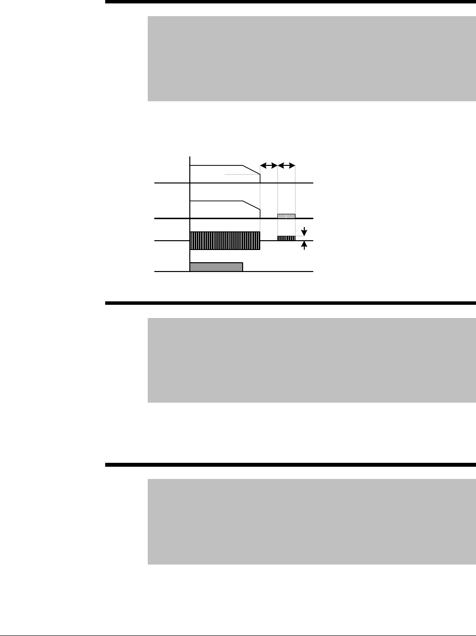
Parameter Descriptions 7-29
F8 DC Brake start frequency
Range: 0.1-60 [Hz]
Default: 5.00
Access Configurable
See Also: P35,P39, F8-F11
Note: Only viewable when P39 – Stop mode select is set to DC
Brake.
Establishes the DC brake start frequency, it can not be set below P35 –
Frequency low limit. Setting this value too high may cause an over current
trip. It can be prevented by adjusting F9 – DC Brake wait time.
F9 DC Brake wait time
Range: 0-60 [sec]
Default: 0.1
Access Configurable
See Also: P35, P39, F8-F11
Note: Only viewable when P39 – Stop mode select is set to DC
Brake.
The drive will hold for the time set in F9 after F8 – DC Brake start frequency
is reached before it applies the voltage level set in F10 – DC Brake Voltage.
Use DC Brake wait time when the load inertia is large to prevent nuisance
trips or damage to the motor.
F10 DC Brake Voltage
Range: 0-200 [%]
Default: 50
Access Configurable
See Also: P32,P35, P39, F8-F11
Note: Only viewable when P39 – Stop mode select is set to DC
Brake.
Sets the DC Brake Voltage as a percent of P32 – Motor Rated Current.
Freq.
Run
command
Voltage
Current
F 8
F9 F11
F10
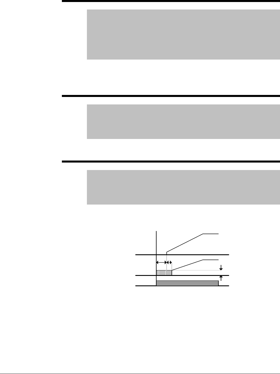
7-30 VS1MD AC Drive User Manual
F11 DC Brake Time
Range: 0-60 [sec]
Default: 1.0
Access Configurable
See Also: P35, P39, F8-F11
Note: Only viewable when P39 – Stop mode select is set to DC
Brake.
Sets the time for F10 – DC Brake Voltage to be applied to the motor after F9
– DC Brake wait time. Setting F10 or F11 to zero will disable the DC Brake
function. In case of DC Brake at high load inertia and frequency, change
the DC brake controller gain according to H37 set value.
F12 DC Brake start voltage
Range: 0-200 [%]
Default: 50
Access Configurable
See Also: F12, t1-t8
This parameter sets the amount of DC voltage before a motor starts to run.
It is set as percentage of P33 – Motor rated current.
F13 DC Brake start time
Range: 0-60 [sec]
Default: 0
Access Configurable
See Also: F12, t1-t8
DC voltage is applied to the motor for DC Brake start time before motor
accelerates.
Setting F12 or F13 to 0 will disable the Starting DC brake. After F13 – DC
Brake start time, the frequency is increased. If a digital input (t1~t8) is set
for 11 – DC brake during start, the voltage is not released until the input is
opened. The drive will accelerate with dc voltage applied until the input is
open.
Freq.
Voltage
Run
command
F13 t
F12
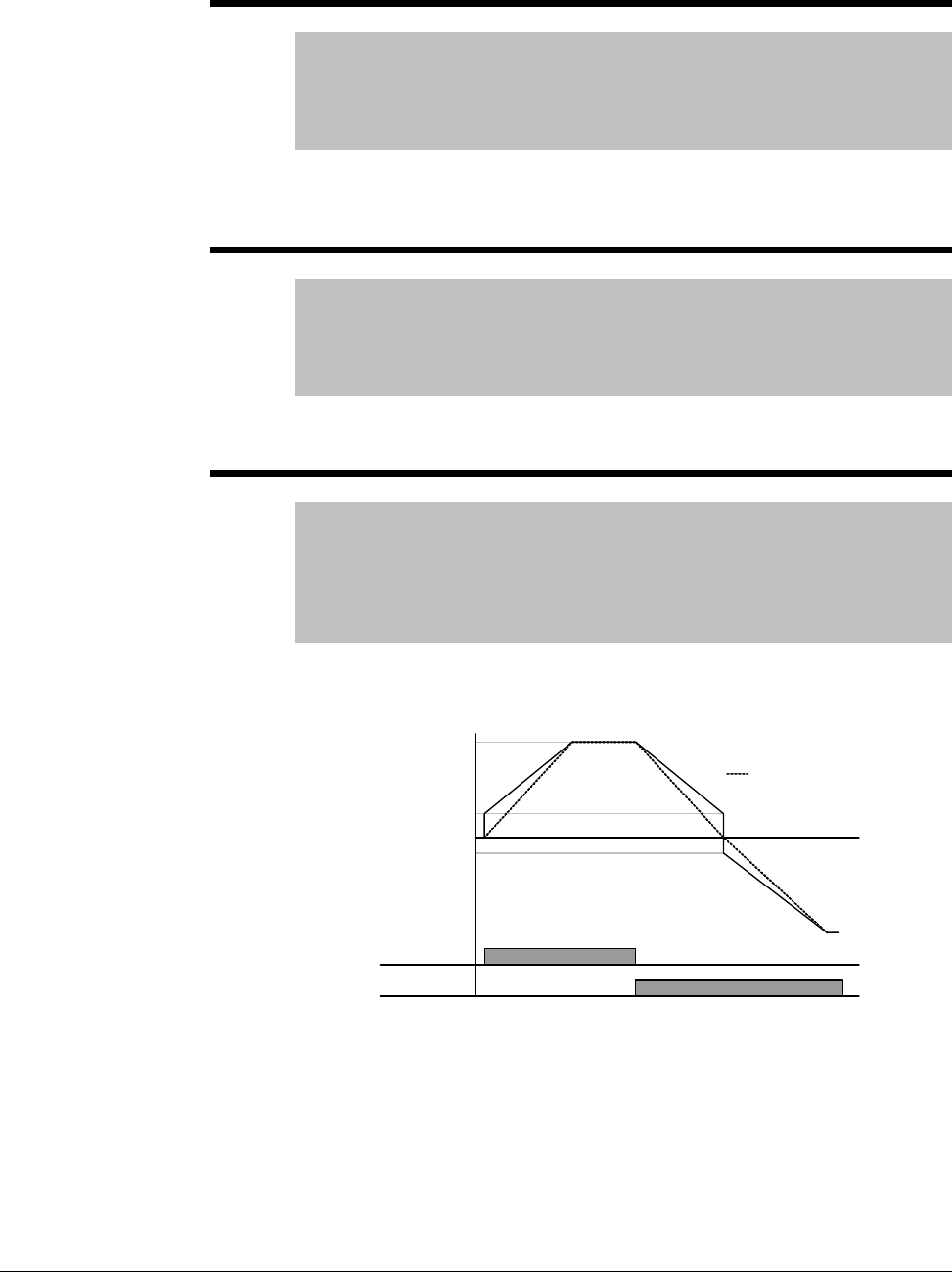
Parameter Descriptions 7-31
F14 Time for magnetizing a motor
Range: 0-60 [sec]
Default: 0.1
Access Configurable
See Also: P30, P32, H32, H34, H40, H42, H44
This parameter accelerates the motor after pre-exciting the motor for the set
time. The amount of the pre-exciting current is set in H34 – Motor no load
current.
F20 Jog Frequency
Range: 0-400 [Hz]
Default: 10.00
Access Tunable
See Also: P36, t1-t8
This parameter sets the Jog Frequency, it cannot be set above P36 –
Frequency High Limit. Jog is only available in 2-wire control mode.
F27 Torque Boost select
Range: 0=Manual Torque Boost
1=Auto Torque Boost
Default: 0
Access Configurable
See Also: F28-F29, H34, H41-42
If F27 = 0, set manual torque boost values in F28 and F29.
If F27 = 1 (Auto toque boost), the inverter automatically calculates torque
boost values using motor parameters and outputs the corresponding
voltage. Before enabling Auto torque boost, H34 – No load current and H42
– Stator resistance must be set properly.
FX
Time
RX
Voltage
F28 - FX
torque boost
No torque boost
100%
F29 - RX
torque boost
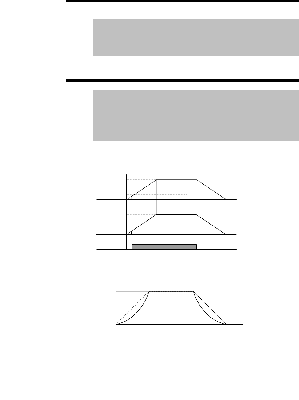
7-32 VS1MD AC Drive User Manual
F28 Torque boost in forward direction
F29 Torque boost in reverse direction
Range: 0-15 [%]
Default: 2
Access Configurable
See Also: F27-F29
This parameter sets the amount of torque boost applied to a motor during
forward or reverse run. It is set as a percent of maximum output voltage.
F30 V/F Pattern
Range: 0=Linear
1=Square
2=User V/F
Default: 0
Access Configurable
See Also: P34, P35, F31-F38, H40
Selects a pattern for the drive.
0 = Linear volts per hertz ratio from P35 – Frequency low limit to P34 –
Base frequency.
1 = Squared volts per hertz ratio. Applications are fans, pumps or variable
torque.
Run
command
Freq. Start freq.
Base freq.
Voltage
Inverter rated
voltage
Freq.
Base freq.
100%
Voltage

Parameter Descriptions 7-33
2 = User V/F is a custom volts per hertz pattern established using
parameters F31~F38.
F31 User V/F frequency 1
F33 User V/F frequency 2
F35 User V/F frequency 3
F37 User V/F frequency 4
Range: 0 - 400 [Hz]
Default: F31=15, F33=30, F35=45, F37=60
Access Configurable
See Also: P34, P35, F31-F38, H40
When F30 = 2, selects the frequency for each point in a custom volts per
hertz pattern.
F32 User V/F voltage 1
F34 User V/F voltage 2
F36 User V/F voltage 3
F38 User V/F voltage 4
Range: 0-100 [%]
Default: F32=25,F34=5-, F36=75, F38=100
Access Configurable
See Also: P34, P35, F31-F38, H40
When F30 = 2, selects the voltage for each point in a custom volts per hertz
pattern.
Freq
.
Voltage
Start
freq. F31 F33 F35 F37 Base
freq.
F32
F34
F36
F38
100%
Linear
V/F
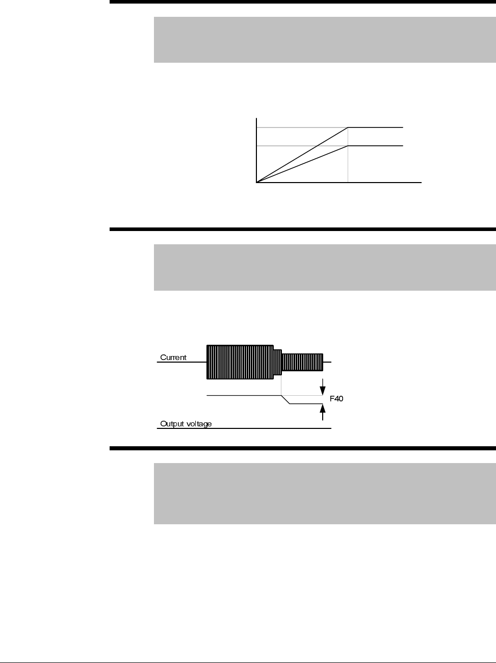
7-34 VS1MD AC Drive User Manual
F39 Output voltage adjustment
Range: 40-110 [%]
Default: 100
Access Configurable
This parameter adjusts the amount of output voltage, set as a percentage of
input voltage. Use when the motor voltage is less than the input voltage.
F40 Energy Savings Level
Range: 0-30 [%]
Default: 0
Access Tunable
This parameter adjusts decreases the output voltage according to load
status. It is set as a percent of the maximum output voltage. When used on
pump and fan applications, it can dramatically reduce energy consumption
by decreasing the output voltage with light loads.
F50 Electronic thermal select
Range: 0 - 1
Default: 0
Access Tunable
Read Only: F51-F53
Setting this parameter to a 1 enables the electronic thermal overload. It
activates when the motor is overheated if current is greater than the value
set in F51 (time-inverse), and the drive output is turned off for the preset
time.
Only viewable when F50 = 1 (Electronic Thermal Overload).
Freq
.
Voltage
Base freq.
100%
70%
100% setting
70% setting
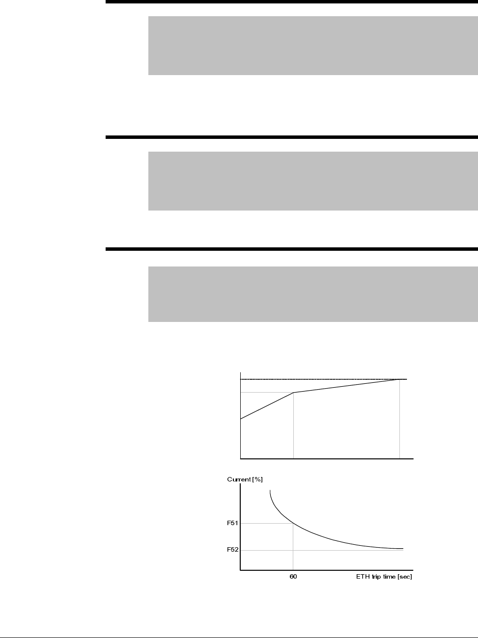
Parameter Descriptions 7-35
F51 Electronic thermal level for 1 minute
Range: 50-200 [%]
Default: 150
Access Tunable
See Also: F50, F52-F53
This parameter sets the maximum current capable of flowing to the motor
continuously for 1 minute. The set value is a percentage of P32 – Motor
Rated Current. It can not be set lower than F52 – Electronic thermal level
for continuous.
F52 Electronic thermal level for continuous
Range: 50-15 [%]
Default: 10
Access Tunable
See Also: F50, F51, F53
This parameter sets the amount of current to keep the motor running
continuously. It cannot be set higher than F51 – Electronic thermal level for
1 minute.
F53 Motor cooling method
Range: 0 = Standard Motor
1 = Variable Speed Motor
Default: 00
Access Tunable
For a Standard Motor, cooling effects decrease when a motor is run at low
speed. A Variable Speed motor is a special motor that uses a separately
powered cooling fan to maximize cooling effect even at low speed.
Current for
continuous [ %]
100
95
65
20 60
Freq [ Hz]
F53 = 1
F53 = 2
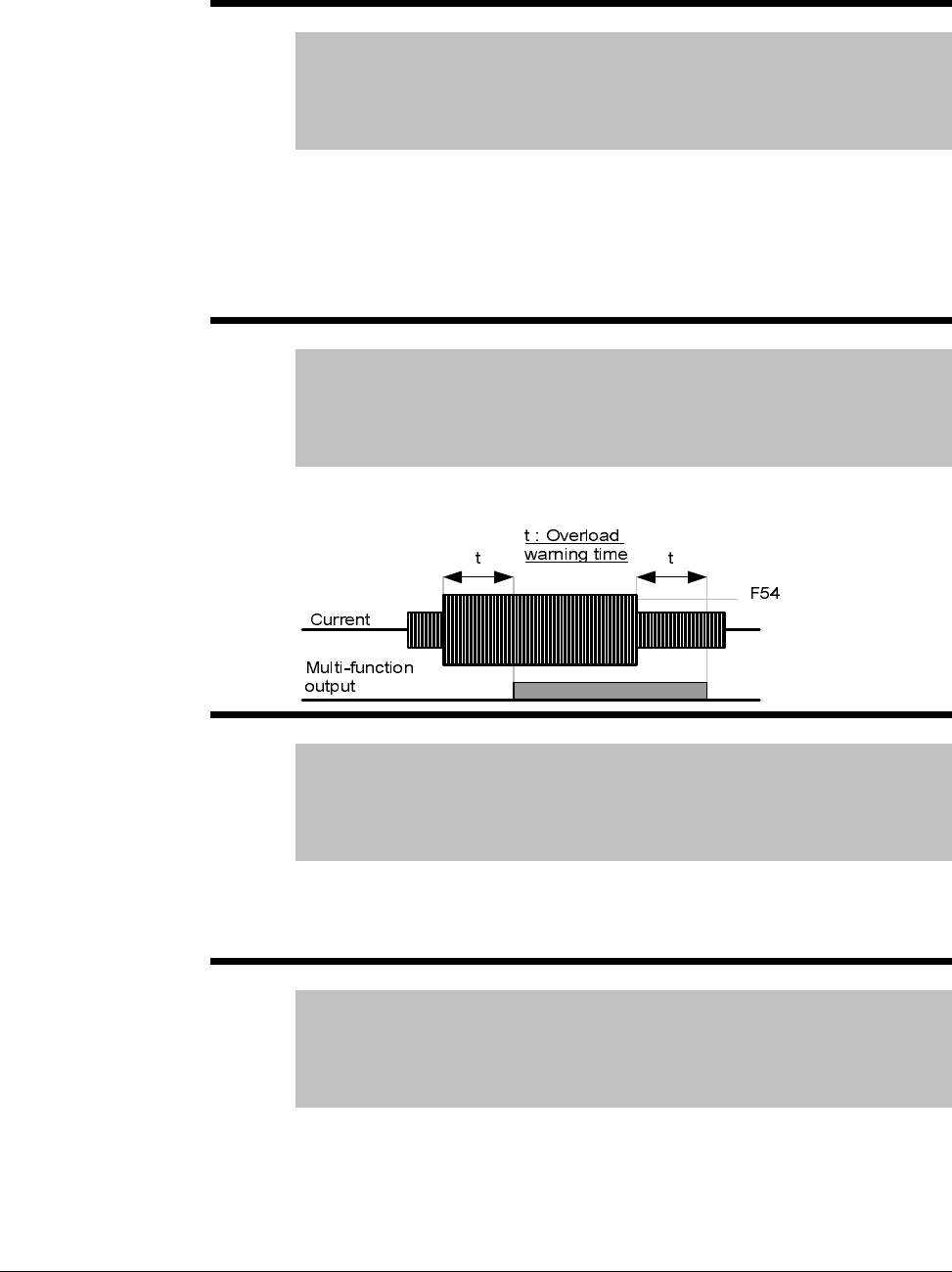
7-36 VS1MD AC Drive User Manual
F54 Overload Warning Level
Range: 30-150 [%]
Default: 150
Access Tunable
See Also: P32, t32, t33, F55
Sets the amount of current to issue an alarm signal at a relay or digital
output terminal (see parameters t32 and t33). The value is set as a
percentage of P32 – Motor Rated Current.
Select an output terminal for this function between MO (Digital Output) and
3A~C (Relay Output). If selecting MO as the output terminal, set t32 = 5
(Overload: OL).
F55 Overload warning time
Range: 0-30 [sec]
Default: 10
Access tunable
See also: P32, t32,t33, F54
This parameter issues an alarm signal when the current greater than F54 –
Overload warning level flows to the motor for F55 – Overload warning time.
F56 Overload trip enable
Range: 0 - 1
Default: 1
Access Tunable
See Also: F57, F58
When set to a 1 = enabled, this parameter turns off the inverter output when
the motor is overloaded. Overload level and time are set in F57 and F58
respectively.
F57 Overload trip level
Range: 30-200 [%]
Default: 180
Access Tunable
See Also: P32, F56, F58
This parameter sets the amount of overload current before the drive trips.
The value is a percentage of P32 – Motor rated current.
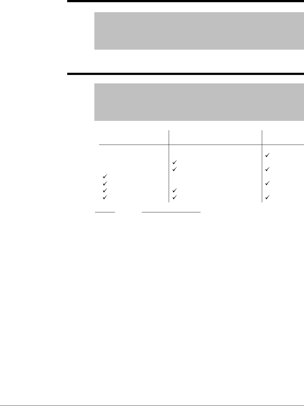
Parameter Descriptions 7-37
F58 Overload trip time
Range: 0-60 [sec]
Default: 60
Access Tunable
See Also: F56, F57
The inverter output is turned off if the current level set in F57 is exceeded
for the time set in F58 – Overload trip time.
F59 Stall Prevention select
Range: 0 - 7
Default: 0
Access Configurable
See Also: t32, t33, F60
During: Function Description:
Acceleration
Constant run
Deceleration
t32 and t33:
Example:
Motor starts deceleration when current exceeds the value
set in F60.
Motor decelerates when current exceeds the value set in
F6.
Motor deceleration is stopped when inverter DC link
voltage rises above a certain voltage level.
The drive outputs signals through either the digital (MO) or
relay output (3A~C) terminals when set = 7 Motor Stall.
Motor stall status can be monitored in the above codes
even if F59 is not active.
F59 = 3; stall prevention active during acceleration and
constant run. When stall prevention is executed during
acceleration or deceleration, accel/decel times may take
longer than the user-setting time to prevent a stall
condition. When stall prevention is activated during
constant run, t1, t2 executed in accordance with the value
set in P41 – Accel Time and P42 – Decel Time.
During Decel
Bit 2
During Constant Run
Bit 1
During Accel
Bit 0
0
1
2
3
4
5
6
7
-
-
-
-
-
-
-
-
-
-
-
-
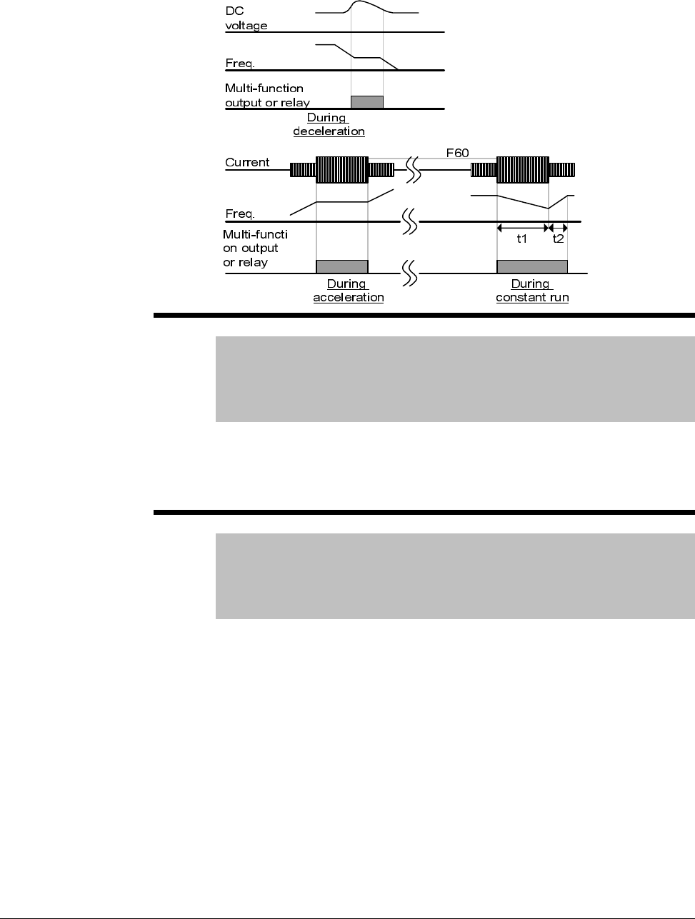
7-38 VS1MD AC Drive User Manual
F60 Stall prevention level
Range: 30-200 [%]
Default: 150
Access Configurable
See Also: P32, F59
This parameter sets the amount of current to activate stall prevention during
acceleration, constant run or deceleration. The value set is a percentage of
P32 – Motor Rated Current.
F63 Save Up/down frequency
Range: 0 -1
Default: 0
Access Configurable
See Also: t1-t8,F64
This parameter decides whether to save the specified frequency during
up/down operation. When 1 is selected, the up/down frequency is saved in
F64.

Parameter Descriptions 7-39
F64 Saved up/down frequency
Range: n/a
Default: 0.00
Access Read Only
See also: t1-t8, F63
Notes: F64 viewable when F63 = 1 (Save up/down frequency)
Stores the up/down frequency if F63 = 1 before the drive stops or
decelerates.
F65 Start Frequency
Range: 0.10 to 10.00 [Hz]
Default: 0.5
Access Configurable
The drive starts to output its voltage at this frequency. It is the low frequency
limit.

7-40 VS1MD AC Drive User Manual
7.6 Function Group 2 Parameters
H0 Jump Code
Range: 0 - 95
Default: 0
Access Tunable
Sets the code to jump directly to a specific parameter within the group.
H1 Last Fault 1
H2 Last Fault 2
H3 Last Fault 3
H4 Last Fault 4
H5 Last Fault 5
Range: n/a
Default: 0
Access Read Only
See also: H6
Stores information on the types of faults, the frequency, the current and the
Accel/Decel condition at the time of fault. The latest fault is automatically
stored in the H1 – Fault History 1. Up to the last five faults can be stored.
When a fault occurs during operation, it can be monitored in the d – display
parameters under nOn. See Chapter 9 – Troubleshooting for information on
fault codes and actions.
H6 Reset Fault History
Range: 0 - 1
Default: 0
Access Tunable
See also: H1-H5
Clears the fault history saved in H1 to H5.
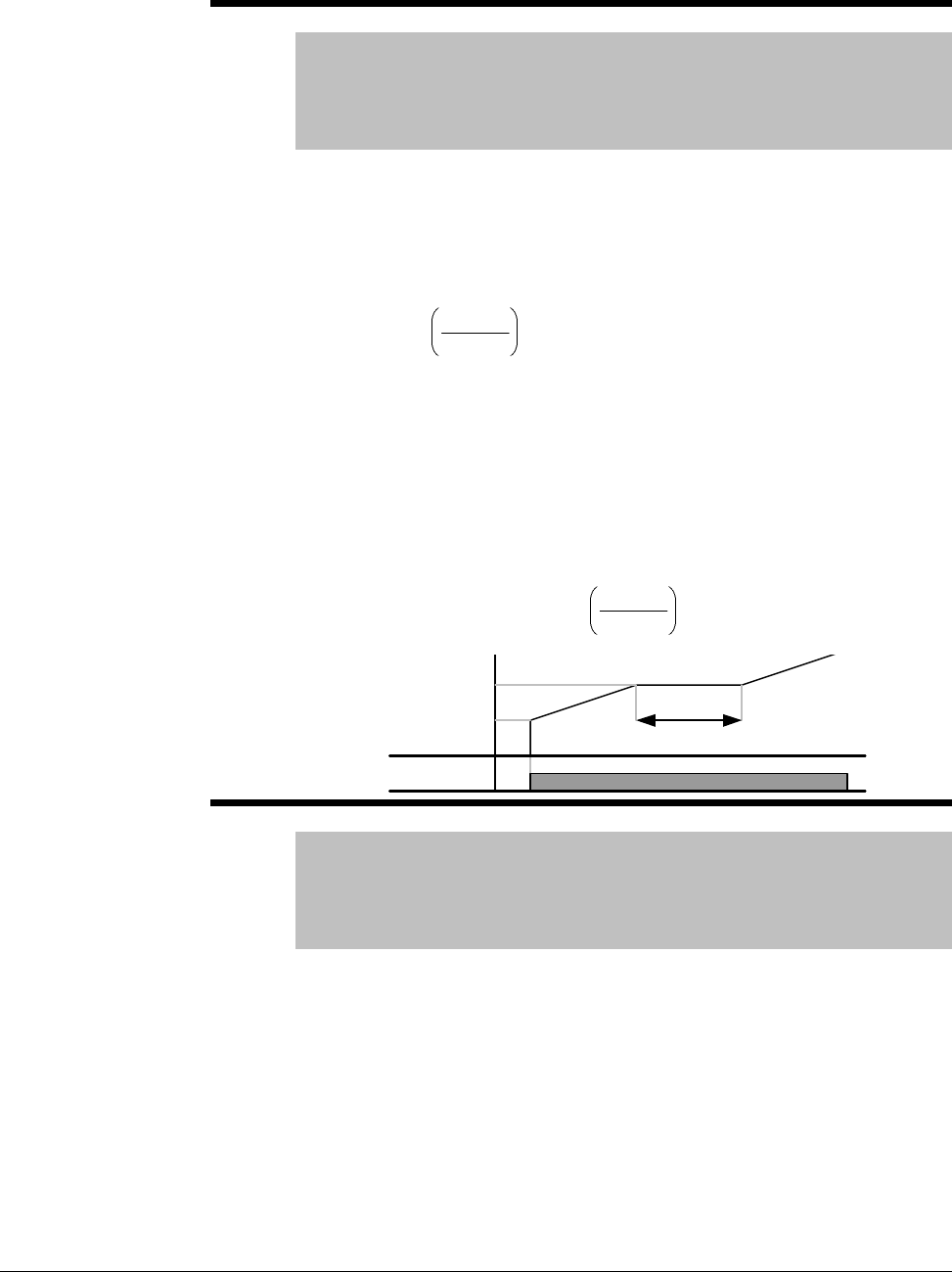
Parameter Descriptions 7-41
H7 Dwell Frequency
Range: 0.1-400 [Hz]
Default: 5.00
Access Configurable
See also: P35, P36, H8
When run frequency is issued, the motor will accelerate after the Dwell
Frequency is applied for the Dwell Time – H8. Dwell frequency can be set
within Frequency High and Low Limits (P35 and P36).
Dwell frequency is used to output torque in an intended direction. It is
useful in hoisting applications to apply torque before releasing a mechanical
brake. Rated slip frequency is calculated by the formula shown below:
Where, = Rated slip frequency
= Rated frequency = = Motor nameplate RPM
= Number of Motor poles
Example:
Rated frequency = 60Hz; Rated RPM = 1740rpm;
Number of motor poles= 4
H8 Dwell Time
Range: 0-10 [sec]
Default: 0.0
Access Configurable
See also: H7
Sets the time for dwell operation.
×
−= 120
Prpm
ff rs
s
f
r
f
rpm
P
H
z
fs2
120
41740
60 =
×
−=
Frequency
Run
command
Dwell time
Dwell freq.
Start freq.
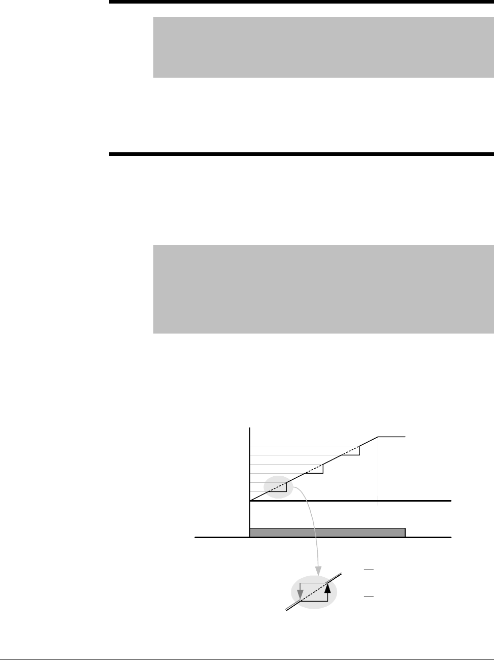
7-42 VS1MD AC Drive User Manual
H10 Skip Frequency Enable
Range: 0 - 1
Default: 0
Access Configurable
See also: H11-H16
Set this parameter = 1 to enable the skip frequency settings configured in
H11 thru H16. When it is desirable to avoid resonance attributable to the
natural frequency of a mechanical system, these parameters allow resonant
frequencies to be skipped. Three different areas of Skip frequency
High/Low limit can be set. During acceleration or deceleration however, the
run frequency within the set area is valid.
H11 Skip Frequency Low Limit 1
H12 Skip Frequency High Limit 1
H13 Skip Frequency Low Limit 2
H14 Skip Frequency High Limit 2
H15 Skip Frequency Low Limit 3
H16 Skip Frequency High Limit 3
Range: 0.1-400 [Hz]
Default: H11=10, H12=15, H13=20, H14=25, H15=30, H16=35
Access Configurable
See Also: H10
Note: Parameters H11-H16 are only viewable when H10 – Skip
Frequency = 1 (Enabled).
Run frequency cannot be set within the range of H11 thru H16. The
frequency values of the low numbered parameters cannot be set above
those of the high numbered ones. Settable within the range of Frequency
High and Low Limits (P35 and P36).Sets the lower limit of frequency range
1 to skip.
Run
command
Freq.
H11
H12
H13
H14
H15
H16
V1(Voltage input)
020mA
10V
I (Current input)
Freq. Up setting
Freq. Down
setting

Parameter Descriptions 7-43
Case 1:If frequency set value (Analog setting via voltage, current, RS485 or
keypad) is within the range of skip frequency, it maintains the low limit value.
If the set value is outside the range, it increases the frequency up to the set
value.
Case 2:In the case of a decreasing frequency setting, if the frequency set
value (Analog setting via voltage, current, RS485 or keypad) is within the
range of skip frequency, it maintains skip frequency high value. If the
setting is outside the range, it decreases frequency to the set value.
H17 S-Curve Accel/Decel Start Side
H18 S-Curve Accel/Decel End Side
Range: 0.1-100 [%]
Default: 40
Access Configurable
See also: P41, P42, F2, F3
Set the speed reference value to form a curve at the start and end cycle of
the acceleration and deceleration curves. If it is set higher, linear zone gets
smaller.
H17 sets the starting and H18 the ending ratio between S-curve and Linear
in ½ of Accel/Decel Ref. Frequency. For smooth Accel/Decel starting,
increase H17 or H18 to extend the S-curve ratio.
Note that setting Frequency Ref. for Accel/Decel (H70) is set to Max Freq
and target freq is set below Max freq. the shape of the S-curve may be
distorted.
Accel time for S-curve setting
Decel time for S-curve setting:
2
1
8
41
2
17
4141 H
P
H
PP ×+×+=
2
1
8
42
2
17
4242 H
P
H
PP ×+×+=
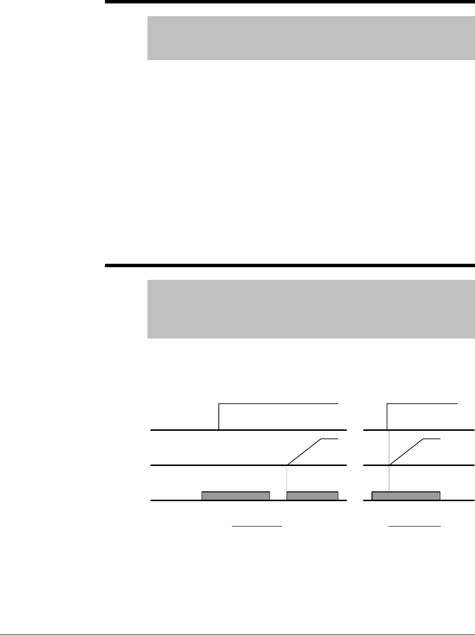
7-44 VS1MD AC Drive User Manual
H19 Phase Loss Protection
Range: 0 - 3n
Default: 0
Access Tunable
Setting H19 to a value other than 0 enables Phase Loss Protection.
Output Phase Loss: Inverter output is shut off in the event of more than one
phase loss among U, V and W.
Input Phase Loss: Inverter output is blocked at the event of more than one
phase loss among R, S and T. If there is no input phase loss, output is shut
off when it is time to replace the DC link capacitor.
Note: Set P32 – Motor Rated Current correctly. If the actual motor rated
current and the value of P32 are different, output phase loss protection
function may not activate correctly.
0 = Not Used
1 = Output phase loss protection
2 = Input phase loss protection
3 = Input/output phase loss protection
H20 Power On Start
Range: 0 - 1
Default: 0
Access Tunable
See also: P38
Setting H20 = 1 enables power on start. This parameter is activated when
P38 – Drive Mode is set to 1 or 2 (Run/Stop via Control Terminal). Motor
will accelerate after AC power is applied and a Forward Run (FX) or
Reverse Run (RX) terminal is ON.
This parameter is inactive if P38 – Drive Mode is set to Keypad or RS485.
ATTENTION:Particular attention must be directed to this function due to
potential hazard as motor starts to run suddenly upon applying AC input
power.
Run
command
Frequency
Input voltage
When H20 is 0 When H20 is 1

Parameter Descriptions 7-45
H21 Auto Restart
Range: 0 - 1
Default: 0
Access Tunable
See also: P38, H26, H27
Setting H21 = 1 enables auto restart. This parameter is activated when P38
– Drive Mode is set to 1 or 2 (Run/Stop via Control Terminal). Motor will
accelerate after a fault condition is reset. A Forward Run (FX) or Reverse
Run (RX) terminal must be ON to Auto Restart.
ATTENTION:Particular attention must be directed to this function due to
potential hazard as motor starts to run suddenly after the fault is cleared.
H22 Speed Search Select
Range: 0 - 15
Default: 0
Access Configurable
See also: t32, t33, H23-H27
This parameter is active to prevent any possible fault when the inverter
outputs its voltage to the running motor. See Chapter 8 – Customizing Your
Application for details on setting this parameter.
H23 Spped Search Current Level
Range: 80 - 200 [%]
Default: 100
Access Tunable
See also: P32, H22, H24-H27
This parameter limits the amount of current during speed search. The value
is a percentage of P32 – Motor Rated Current. See Chapter 8 –
Customizing Your Application for details on setting this parameter.
Run
command
Reset
Frequency
When H21 is 0 When H21 is 1

7-46 VS1MD AC Drive User Manual
H24 Speed Search P Gain
H25 Speed Search I Gain
Range: 0-9999
Default: 100
Access Tunable
Settings H24 and H25 are used to set the Proportional and Integral gain
used for Speed Search PI Controller. See Chapter 8 – Customizing Your
Application for details on setting this parameter.
H26 Auto Restart Attempts
Range: 0-10
Default: 0
Access Tunable
See Also: H21, H27
This parameter sets the number of restart tries after a fault occurs. Auto
restart becomes active after the time is reached in H27 – Auto Restart Time.
Auto Restart is deactivated if the number of faults exceeds the value in H26
– Auto Restart Attempts.
H26 is reset back to its entered value if STOP key or a reset via the control
terminal is activated. If no trip occurs for 30 seconds after the auto restart
operation, H26 is reset.
It is not possible to restart (auto restart becomes deactivated) if the drive
faults due to a Low Voltage (Lvt), Emergency Stop (EST), Inverter Overheat
(Oht) or a Hardware Trip (HWt) fault. This parameter sets the number of
restart tries after a fault occurs. Auto restart becomes active after the time
is reached in H27 – Auto Restart Time. Auto Restart is deactivated if the
number of faults exceeds the value in H26 – Auto Restart Attempts.
H27 Auto Restart Time
Range: 0-60 [sec]
Default: 1.0
Access Tunable
See Also: H21, H27
This parameter sets the amount of time between auto restart attempts.
After the Auto Restart Time, the motor starts acceleration automatically.

Parameter Descriptions 7-47
H32 Slip Frequency
Range: 0-10 [Hz]
Default: 1.67
Access Configurable
See Also: P33, H40
Enter the slip frequency in accordance with the following formula and motor
nameplate.
Where:
fs = Rated Slip Frequency
fr = Rated Frequency
rpm = Motor Nameplate rpm
P = Number of Motor Poles
Example: Rated Freq: 60 Hz; Rated RPM: 1740 rpm; Poles: 4
fs = 60 - ((1740 x 4) / 120) = 2 HZ
H34 No Load Motor Current
Range: 0.1-20 [A]
Default: Based on drive rating
Access Configurable
Enter the current value detected when the motor is rotating at rated speed
(remove any load connected to the motor shaft). For applications where it is
difficult to measure the no load current, enter a value of 50% of the rated
nameplate motor current in this parameter.
H36 Motor Efficiency
Range: 50-100 [%]
Default: 87
Access Configurable
Enter the motor efficiency from the motor nameplate.
f
s=fr -
(
)
rpm x P
120

7-48 VS1MD AC Drive User Manual
H37 Load Inertia Rate
Range: 0=Load inertia rate is less than 10 times that of motor
inertia
1=Load inertia rate equal to approximately 10 times the
motor inertia.
2=Load inertia rate is more than 10 times that of motor
inertia.
Default: 0
Access Configurable
See also: F8-F11, H40
Select range according to the connected inertia in relationship to the motor
inertia.
H39 Carrier Frequency Select
Range: 2-15 [kHz]
Default: 2
Access Tunable
This parameter affects the audible sound of the motor, noise emission form
the inverter, inverter temperature, and leakage current. If the set value is
higher, the inverter sound is more quiet, but the noise from the inverter and
leakage current will be increased.
H40 Control Mode Select
Range: 0=Volts/Frequency Control
1=Slip Compensation Control
2=PID Feedback Control
3=Sensorless Vector Control
Default: 0
Access Configurable
This parameter selects the control mode for the operation of the drive. See
the following description of control method and the corresponding
parameters for adjustment to each.

Parameter Descriptions 7-49
Volts per Hertz:
Slip
Compensation:
PID Feedback:
Sensorless
Vector:
Basic Operation of the Drive, set standard motor
parameters:
P30 – Motor Hp
P32 – Motor Rated Current
P33 – Motor PolesF30 – V/F Pattern
This function enables the motor to run in constant speed
by compensating inherent slip in an induction motor. Set
parameters:
P30 – Motor Hp
P32 – Motor Rated Current
P33 – Motor Poles
H32 – Rated Slip Freq
H34 – Motor No Load Current
H36 – Motor Efficiency
H37 – Load Inertia
H50 thru H56 (see chapter 8 for advanced PID features)
Open Loop Speed Regulated drive control. Set
parameters:
P30 – Motor Hp
P32 – Motor Rated Current
H32 – Rated Slip Freq
H34 – Motor No Load Current
H41 – Auto tuning
H42 – Stator resistance
H44 – Leakage inductance
F14 – Time for magnetizing
H41 Auto-Tuning
Range: 0 - 1
Default: 0
Access Configurable
See also: H40, H42, H44
If this parameter is set to a 1, it automatically measures the values to assign
for parameters H42 – Stator Resistance and H44 – Leakage Inductance.
H42 Stator Resistance (Rs)
Range: 0-28 [Ω]
Default: n/a
Access Configurable
See also: H40, H41, H44
This is the value of the motor stator resistance.

7-50 VS1MD AC Drive User Manual
H44 Leakage Inductance (Lσ)
Range: 0-300.0 [mH]
Default: Based on drive rating
Access Configurable
See also: H40, H41, H42
This is the leakage inductance of the stator and rotor of the motor.
H45 Sensorless P Gain
H46 Sensorless I Gain
Range: 0-32767
Default: H44=1000, H45=100
Access Configurable
See also: H40
Note: Set H40 = 3 (Sensorless Vector Control) to display these
parameters.
Proportional and Integral gain for Sensorless Vector Control.
H50 PID Feedback Selection
Range: 0=Terminal I Input (0-20 mA)
1=Terminal V1 Input (0-10V)
Default: Based on drive rating
Access Configurable
See Also: H40, H50-H56
Selects the source for the PID loop feedback.
H51 P Gain for PID
Range: 0 - 999.9%
Default: 300.0
Access Configurable
See Also: H40, H50-H56
These parameter sets the Proportional gain for the PID Controller.
H52 I Gain for PID
Range: 0.1-32.0[sec]
Default: 1.0
Access Tunable
See Also: H40, H50-H56
These parameter sets the Integral gain for the PID Controller.

Parameter Descriptions 7-51
H53 D Gain for PID
Range: 0-30.0[sec]
Default: 0.0
Access Tunable
See Also: H40, H50-H56
These parameter sets the Differential gain for the PID Controller.
H54 F Gain for PID
Range: 0-999.9[%]
Default: 0.0
Access Tunable
See Also: H40, H50-H56
This is the Feed forward gain for the PID controller.
H55 PID output frequency high limit
H56 PID output frequency low limit
Range: 0.1-400[Hz]
Default: 60.00
Access Tunable
See Also: H40, H50-H56
These parameters set the limits for the output frequency through the PID
control.
H60 Self Diagnostics Select
Range: 0 - 3
Default: 0
Access Configurable
See Also: t1-t8
0 = Self-diagnostic disabled
1 = IGBT fault/ground fault
2 = Output phase short & open/ground fault
3 = Ground Fault
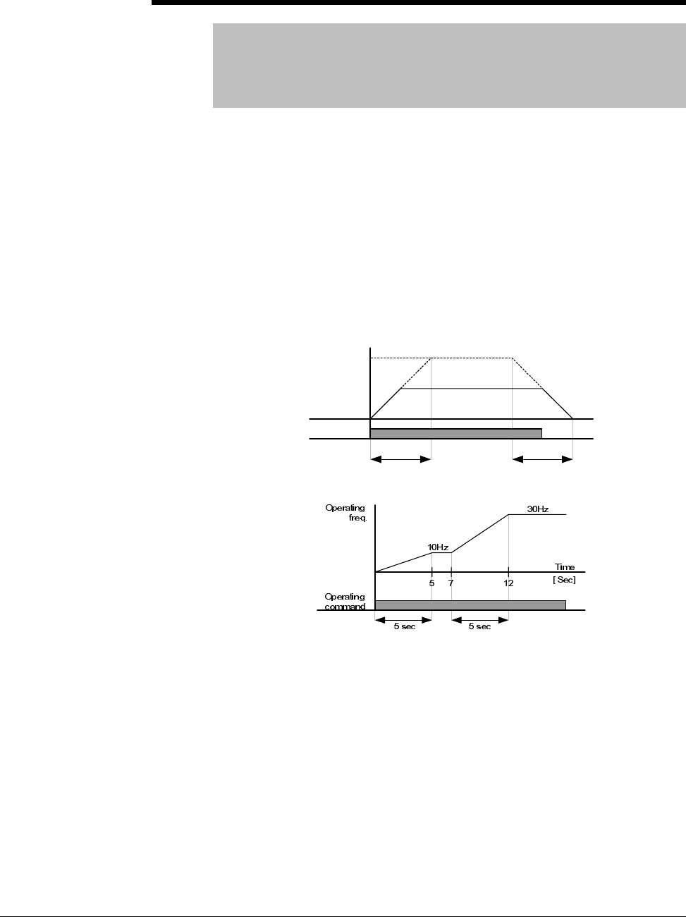
7-52 VS1MD AC Drive User Manual
H70 Frequency Reference for Accel/Decel
Range: 0 - 1
Default: 0
Access Configurable
See Also: P36, P41, P42, H71
0 = Based on P36 – Frequency High Limit
1 = Based on Delta Frequency
Set the desired Accel/Decel time sin P41 and P42. If H70 = 0, the
acceleration and deceleration time is the time that it takes to reach
maximum frequency from 0 hertz. If you set H70 to 1 = Delta Frequency,
Accel/Decel time is the time that it takes to reach target frequency from a
constant run frequency (current operating frequency). To scale the time
units for accel/decel set parameter H71.
H70 = 0 (Max Frequency)
H70 = 1 (Delta Frequency)
Run
command
Run Freq.
30Hz
Accel time Decel time
Max. freq.
60Hz

Parameter Descriptions 7-53
H71 Accel/Decel Time Scale
Range: 0 - 2
Default: 1
Access Tunable
See Also: P36, P41, P42, H70
This parameter is used to scale the time units for the accel/decel ramp. The
display for the VS1MD is available up to 5-digits. Therefore, if time unit is
set to 0.01 sec for example, maximum accel/decel time would be 600.00
seconds.
H72 Power-On Display
Range: 0 - 9
Default: 0
Access Configurable
See Also: d0-d9, H74
This parameter selects the parameter to display on the keypad when power
is applied.
H74 Gain for Motor RPM Display
Range: 1-100 [%]
Default: 100
Access Configurable
See Also: d1, H72
This parameter is used to change the motor rpm display to a scaled custom
factor. When H40 = 0 (V/F Control) or 1 (PID Control), the inverter output
frequency is displayed in RPM suing the formula below. Motor slip is not
considered.
0 = Setting Unit: 0.01 sec Range: 0.01 ~ 600.00
1 = Setting Unit: 0.1 sec 0.1 ~ 6000.0
2 = Setting Unit: 1 sec 1 ~ 60000
0 = Frequency Command 1 = Motor RPM
2 = Output Current 3 = Output Voltage
4 = Output Power 5 = Output Torque
6 = DC Link Voltage 7 = Digital Input Status
8 = Digital Output Status 9 = Software Version
100
7
4
32
120 H
P
f
RPM ×
×
=
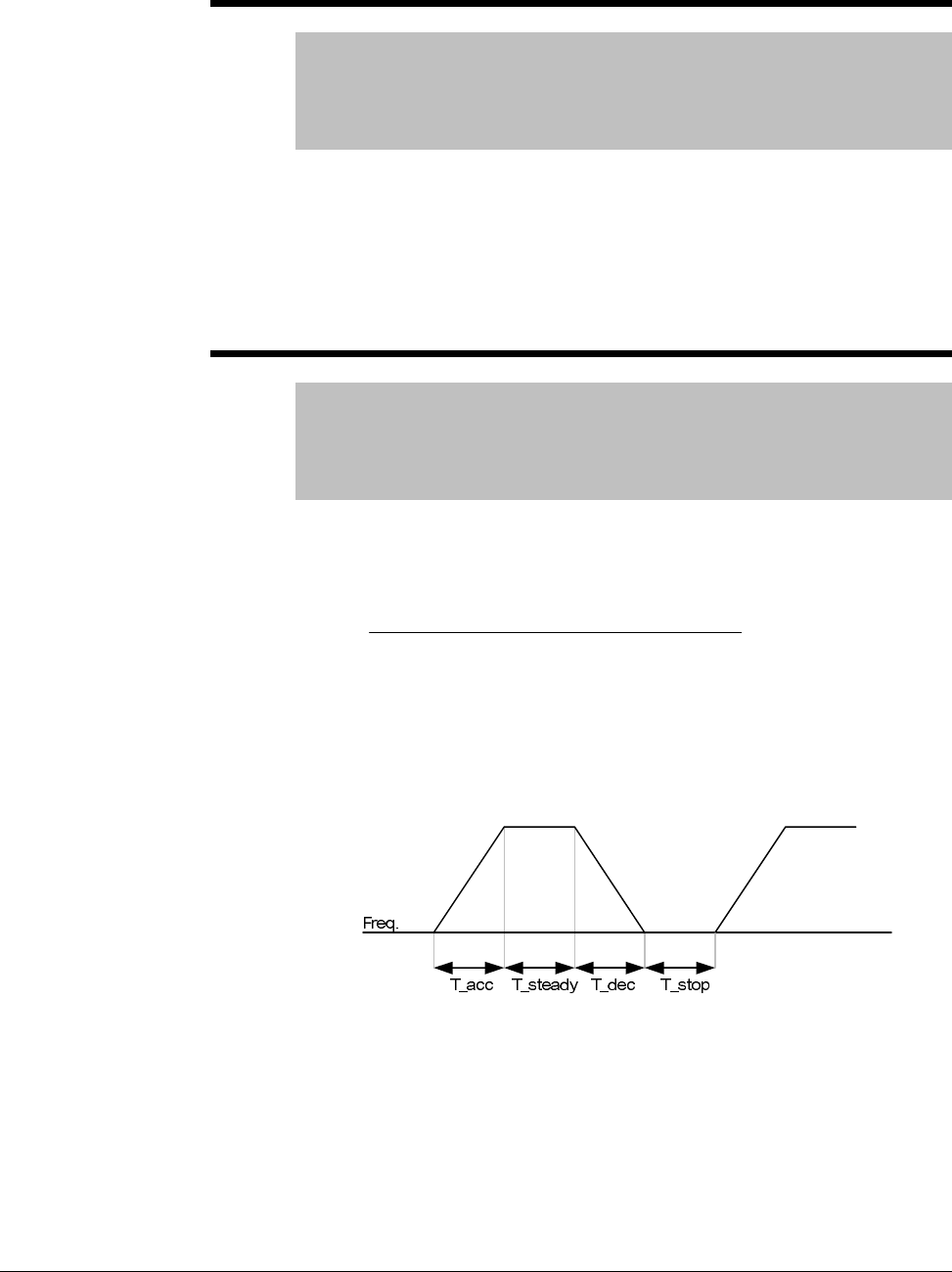
7-54 VS1MD AC Drive User Manual
H75 DB Resistor Select
Range: 0 - 1
Default: 1
Access Configurable
See Also: H76
0 = Unlimited
1 = Limited by setting in H76
ATTENTION:Take caution when DB resistor is used over its Watt rating.
Fire may result from resistor overheat. When resistor having heat detection
sensor is used, sensor output can be used as external trip signal in digital
input.
H76 DB Resistor Operating Rate
Range: 0-30[%]
Default: 10
Access Configurable
See Also: H75
Sets the percent of DB resistor operating rate to be activated during one
sequence of operation. Continuous usage rate is a maximum of 15
seconds.
Example 1)
T_acc: Acceleration time to reach a setting freq.
T_steady: Time for constant speed operation at setting freq.
T_dec: Time to decelerate to lower freq. than that in constant speed
or time to stop from freq. in constant speed.
T_stop: waiting time at a stop before operation is resumed.
[%
]
100
____
_
76 ×
+++
=stopTdecTsteadyTaccT
decT
H
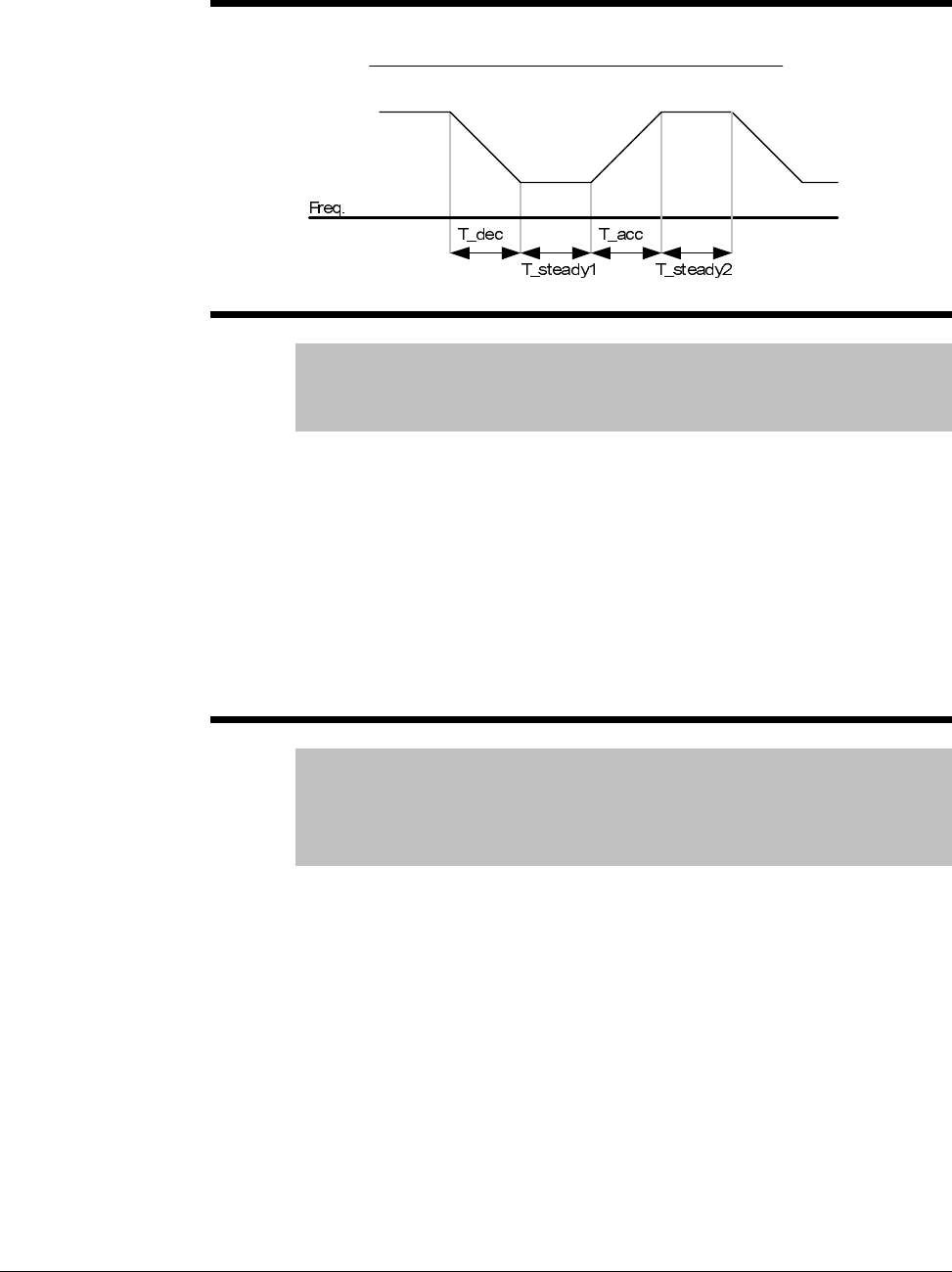
Parameter Descriptions 7-55
Example 2)
H77 Cooling Fan Control
Range: 0 - 1
Default: 0
Access Configurable
This parameter determines if the cooling fan for the drive will always
operate or only run when the temperature of the inverter exceeds the
protective temperature limit.
0 = Always ON, cooling fan operates when power is applied to drive. Fan
turns off when inverter voltage becomes low due to power off.
1 = Fan operates when temp above limit; fan begins to operate when power
is ON and a operating command is ON. Fan turns off when operating
command is turned off. Fan will continue to operate if the heat sink
temperature exceeds a certain limit regardless of operating command. Use
this setting for applications requiring frequent starts and stops.
H78 Operating method when cooling fan fails
Range: 0 - 1
Default: 0
Access Configurable
See Also: t32, t33
This parameter determines if what the drive will do if the cooling fan fails.
0 = Continuous operation when cooling fan malfunctions
Setting t32 or t33 = 18 (Cooling Fan Fault Alarm) will send an alarm signal
to the output.
ATTENTION:If operation is continued after a fan trip occurs, an overheat
trip may happen and protective functions may be activated. It may also
reduce the life of main board components due to a rise in inverter internal
temperatures.
[%
]
100
2__1__
_
76 ×
+++
=steadyTaccTsteadyTdecT
decT
H
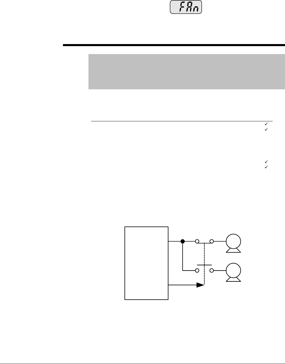
7-56 VS1MD AC Drive User Manual
1 = Operation stops when cooling fan malfunctions
When cooling fan fault occurs, message is displayed on the
LED and operation is stopped. If t32 and/or t33 is set to 17 (Fault Output),
fault message is displayed.
H81 -
H90 Second Motor Parameters
Range: See below
Default: See below
Access Configurable
See Also: t1-t8
These parameters activate when a selected terminal is ON and one of the
t1 thru t8 terminals is set for 12 (2nd Motor Select).
Use these settings when an inverter operates two motors connected to two
different types of loads. 2nd motor operation does not drive two motors at
the same time. When first selected motor operation is stopped, select a
terminal for the second motor and define H81 thru H90 to run the second
motor.
Sets the V/F pattern for the second motor.
Param. Description Range Factory Default Adj. run
H81 Accel Time 0 ~ 60000 Sec 1.0
H82 Decel Time 0 ~ 60000 Sec 5.0
H83 Base Freq 30 ~ 400 Hz 60.0 -
H84 V/F Pattern 0 ~ 2 0 -
H85 FX Torque Boost 0 ~ 15 % 5 -
H86 RX Torque Boost 0 ~ 15 % 5 -
H87 Stall Level 30 ~ 150 % 150 -
H88 1 Min Overload Level 50 ~ 200 % 150
H89 Continuous Overload Level 50 ~ 150 % 100
H90 Motor Rated Current 0.1 ~ 50 Amps 26.3 -
M 1
M 2
VS1MD
P8

Parameter Descriptions 7-57
H91 Parameter Read
H92 Parameter Write
Range: 0-1
Default: 0
Access Configurable
H91 Copies the parameters from the drive and saves them into a remote
keypad.
H92 Copies the saved file in a remote keypad and writes it to the drive.
H93 Parameter Initialize
Range: 0 - 5
Default: 0
Access Configurable
This parameter is used to initialize the drive settings back to their factory
default values.
0 = No Action
1 = All parameters set to factory defaults
To reset individual groups only and not all parameters select one of the
following:
Press the ENTER key after setting H93. H93 will be displayed again after
initialization.
H94 Password Register
Range: 0-FFFF
Default: 0
Access Tunable
See Also: H95
This parameter is used to assign a password for the drive.
H95 Parameter Lock
Range: 0 -FFFF
Default: 0
Access Tunable
See Also: H94
This parameter is able to lock or unlock parameters by typing the password
registered in H94.
2 = P Group Parameter Reset 3 = F Group Parameter Reset
4 = H Group Parameter Reset 5 = t Group Parameter Reset

7-58 VS1MD AC Drive User Manual

Customizing for Your Application 8-1
CHAPTER 8
Customizing for Your Application
8.1 Frequency Mode
8.1.1 Keypad Frequency Setting 1
Note: When remote keypad is connected, keypad keys on the body are deactivated.
Group Code Parameter Name Setting Range Initial Unit
Drive
group P37 [Frequency Command] - 0 to
400 0.00 Hz
P40 [Frequency Setting
Method] 1 1 to 7 1
Step 1. Set P40 [Frequency mode] to “1”.
Step 2. Set the desired frequency in P37 and press the Prog/Ent ( ) key to enter
the value into memory.
Step 3. The value can not be set above P36 [Frequency Hiigh Limit].
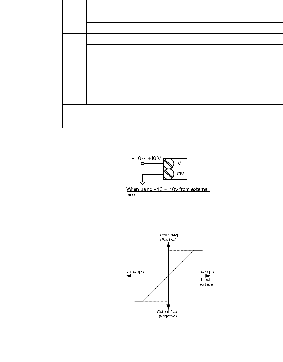
8-2 VS1-MD AC Drive User Manual
8.1.2 Frequency Setting via –10 to +10[V] Input
Apply –10V to +10V signal between V1 and CM terminal.
Output frequency corresponding to –10V to +10V input voltage to V1 terminal
Group Code Parameter Name Setting Range Initial Unit
Drive
group P37 [Frequency Command] - 0 to400 0.00 Hz
P40 [Frequency Mode] 2 1 to 7 1
t40 TO
t44 t36 [NV Input Minimum Voltage] - 0 to -10 0.0 V
t37 [Frequency Corresponding to
t36] - 0 to 400 0.00 Hz
t38 [NV Input Max Voltage] - 0 to 10 10.00 V
t39 [Frequency Corresponding to
t38] - 0 to 400 60.00 Hz
t40 to
t44 [V1 Input]
Step 1. Set P40 [Frequency Setting Method] to “2”.
Step 2. The set frequency can be monitored in D-0[Frequency Command].
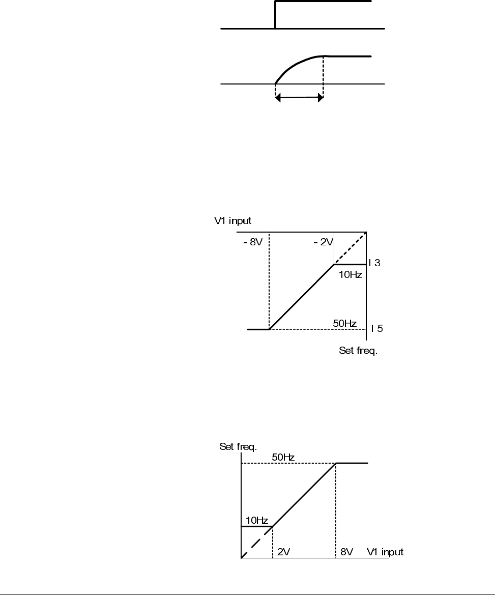
Customizing for Your Application 8-3
I1 (Filter time constant for NV input): Effective for eliminating noise in the frequency
setting circuit. Increase the filter time constant if steady operation cannot be
performed due to noise. A higher setting results in slower response (t gets longer).
t36 to t39: Setting input range and corresponding frequency to -10V to 0V V1 input
voltage
Ex) when minimum (-) input voltage is -2V with corresponding frequency 10Hz and
Max voltage is –8V with run freq. 50Hz.
t40 to t44: Setting input range and corresponding frequency to 0 to +10V V1 input
voltage
Ex) when minimum (+) input voltage is 2V with corresponding frequency 10Hz and
Max voltage is 8V with run freq.
t
V1 Input
Set Freq.
t38 t36
t44
t42
t41 t49
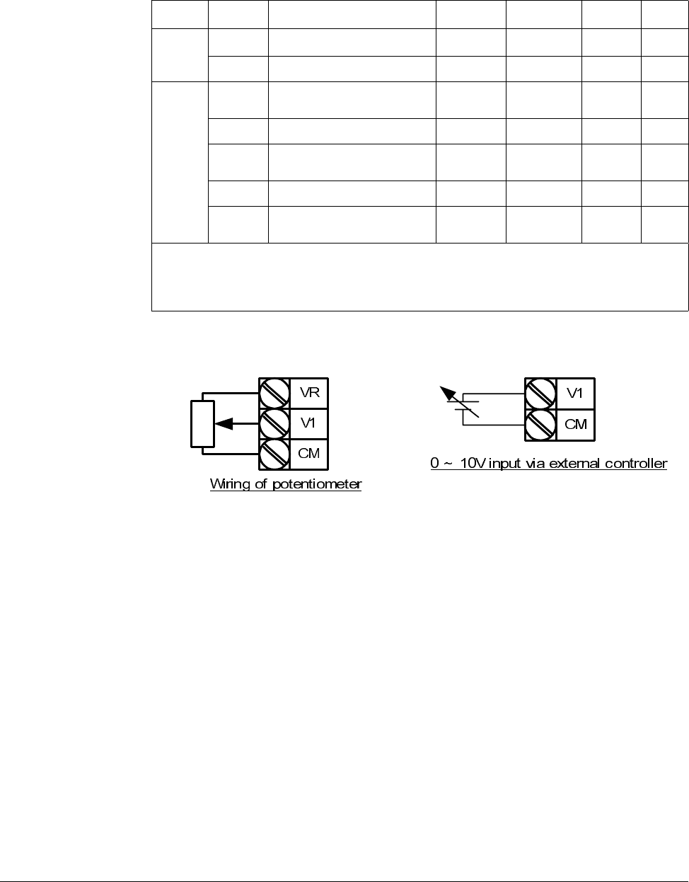
8-4 VS1-MD AC Drive User Manual
8.1.3 Frequency Setting via 0 to 10 [V] Input or Terminal Potentiometer
Wire the terminals as shown below.
Group Code Parameter Name Setting Range Initial Unit
Drive
group
P37 [Frequency Command] - 0 to 400 0.00 Hz
P40 [Frequency Setting Method] 3 1 to 7 1
I/O
group
t40 [Filter Time Constant for V1
Input] 10 0 to 9999 10
t41 [V1 Input Min Voltage] - 0 to 10 0 V
t42 [Frequency corresponding to I
7] - 0 to 400 0.00 Hz
t43 [V1 Input Max Voltage] - 0 to 10 10 V
t44 [Frequency Corresponding to
I 9] - 0 to 400 60.00 Hz
Step 1. Set P40 [Frequency Setting Method] to “3”
Step 2. 0-10V can be directly applied from an external controller or a
potentiometer connected on terminals VR, V1 and CM.

Customizing for Your Application 8-5
8.1.4 Frequency Setting via 0 to 20 [mA] Input
8.1.5 Frequency Setting via -10 to +10 V Voltage Input + 0 to 20 mA
Input
Override function allows more precise control and a faster response by combining
Main and Auxiliary speed input. Fast response can be achieved via Main speed and
precise control can be accomplished by Aux. speed if the accuracy of Main/Aux speed
is set differently.
Follow the settings shown in the table below when Main speed is given via 0 to 20mA
with Aux. speed via V1 terminal (–10 to 10V).
Group Code Parameter Name Setting Range Initial Unit
Drive
group
P37 [Frequency Command] - 0 to 400 0.00 Hz
P40 [Frequency Setting Method] 4 1 to 7 1
I/O
group
t45 [Filter Time Constant for I Input] 10 0 to 9999 10
t46 [I Input Minimum Current] - 0 to 20 4 mA
t47 [Frequency Corresponding to I12] - 0 to 400 0.00 Hz
t48 [I input Max Current] - 0 to 20 20 mA
t49 [Frequency Corresponding to I14] - 0 to 400 60.00 Hz
Step 1. Set P40 [Frequency Setting Method] to “4”.
Step 2. Frequency is set via 0 to 20mA input between I and CM terminal.
Group Code Parameter Name Setting Range Initial Unit
Drive
group
P37 [Frequency Command] - 0 to 400 0.00 Hz
P40 [Frequency Setting Method] 5 1 to 7 1
Step 1. Set P40 [Frequency Setting Method] to “5”.
Step 2. Override function available using Main/Auxiliary speed adjustment
Step 3. Related code: t36, t39, t40, t44, t45, t49
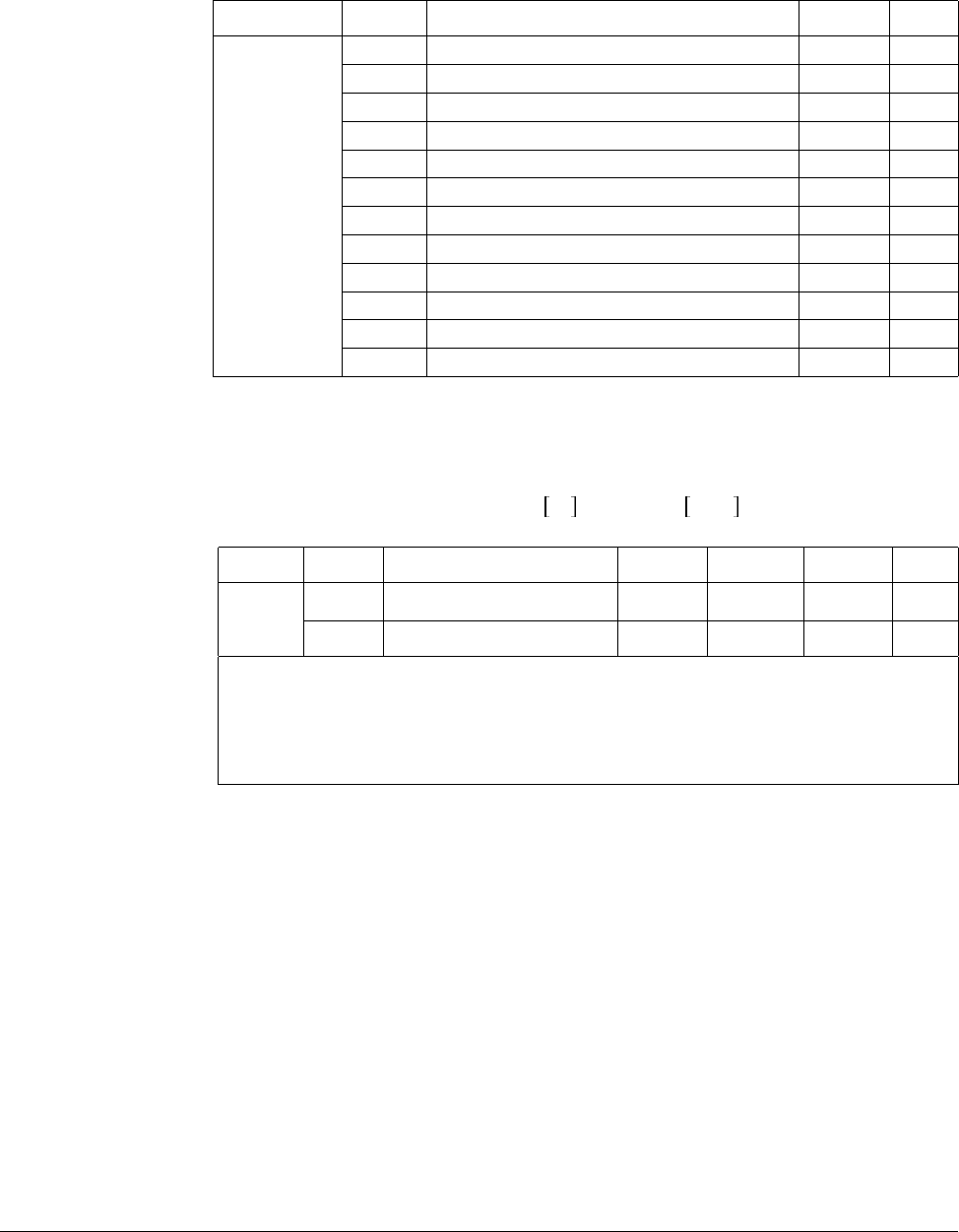
8-6 VS1-MD AC Drive User Manual
When override function is used, select the Main/Aux. speed according to loads used.
After the above parameters are set, if 5V is applied to V1 with 12mA given to terminal
I, output frequency would be 32.5Hz. If –5V is applied to V1 terminal with 12mA given
to terminal I, output frequency would be 27.5Hz.
8.1.6 Frequency Setting via 0 to 10 V + 0 to 20 mA Input
Group Code Parameter Name Setting Unit
I/O group
t36 [NV Input Min Voltage] 0 V
t37 [Frequency Corresponding to t36] 0.00 Hz
t38 [NV Input Max Voltage] 10.00 V
t39 [Frequency Corresponding to t38] 5.00 Hz
t41 [V1 Input Min Voltage] 0 V
t42 [Frequency Corresponding to t41] 0.00 Hz
t43 [V1 Input Max Voltage] 10 V
t44 [Frequency Corresponding to t43] 5.00 Hz
t46 [I Input Minimum Current] 4 mA
t47 [Frequency Corresponding to t46] 0.00 Hz
t48 [I Input Max Current] 20 mA
t49 [Frequency Corresponding to t48] 60.00 Hz
Group Code Parameter Name Setting Range Initial Unit
Drive
group
P37 [Frequency Command] - 0 to 400 0.00 Hz
P40 [Frequency Mode] 6 1 to 7 1
Step 1. Set P40 [Frequency Setting Method] to “6”.
Step 2. Related code: t40 to t44, t45 to t49
Step 3. Refer to Frequency setting via -10 to +10V voltage input + 0 to 20mA
input.
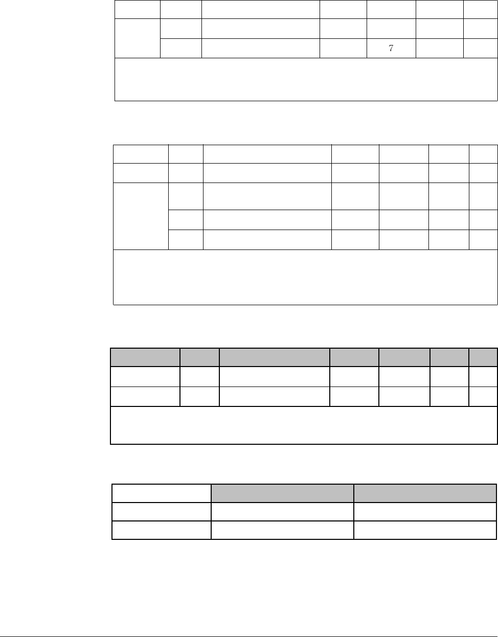
Customizing for Your Application 8-7
8.1.7 Frequency Setting via RS 485 Communication
8.1.8 Operating Command via RS485 Communication
8.1.9 Rotating Direction Selection via –10 to +10[V] Input of V1 Terminal
Motor runs in Forward direction when input voltage to V1-CM is between 0 and 10[V]
and FWD RUN command is active. When input voltage polarity is reversed to –10 to
0[V] during FWD RUN, motor decelerates to stop and runs in reverse direction.
Group Code Parameter Name Setting Range Initial Unit
Drive
group
P37 [Frequency Command] - 0 to400 0.00 Hz
P40 [Frequency Setting Method] 7 1 to 1
Set P40 [Frequency Setting Method] to “7”.
Related code: t59 - t61
Refer to Appendix D. RS485 communication.
Group Code Parameter Name Setting Range Initial Unit
Drive group P38 [Drive Mode] 3 0 to 3 1
I/O group
t59 [Communication Protocol
Selection] -0 to 10
t60 [Inverter Number] - 1 to 250 1
t61 [Baud Rate] - 0 to 4 3
Step 1. Set P38 [Drive Mode] to “3”.
Step 2. Set t59, t60 and t61 correctly.
Step 3. Drive operation is performed via RS485 communication.
Group Code Parameter Name Setting Range Initial Unit
Drive group P40 [Frequency Setting] 2 1 to 7 1
P38 [Drive Mode] - 0 to 3 1
Step 1. Set P40 to 2.
Step 2. Inverter is operating as the table below regardless of Drive mode setting.
FWD RUN Command REV RUN Command
0 to +10 [V] FWD RUN REV RUN
-10 to 0 [V] REV RUN FWD RUN
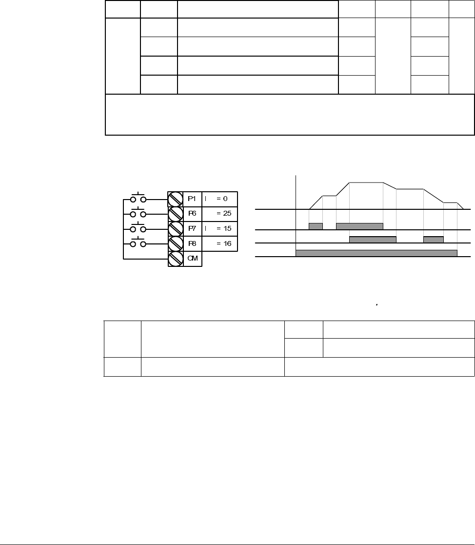
8-8 VS1-MD AC Drive User Manual
Motor runs in Reverse direction when input voltage to V1-CM is between 0 and 10[V]
and REV RUN command is active. When input voltage polarity is reversed to –10 to
0[V], motor decelerates to stop and runs in forward direction.
8.2 UP-Down
Up/down Save function: If F63, ‘Save up/down frequency’, is set to 1, the frequency
before the inverter was stopped or decelerated is saved in F64
The Up/down frequency can be initialized by setting the multi-function input terminal
as ‘Up/Down Save Frequency Initialization’.
Group Display Parameter Name Setting Range Default Unit
I/O
group
t1 [Multi-function Input Terminal P1 Selection] 0
0 to 25
0
to to
t7 [Multi-function Input Terminal P7 Selection] 15 6
t8 [Multi-function Input Terminal P8 Selection] 16 7
Select terminals for Up-Down operation from P1-P8.
If P7 and P8 are selected, set t7 and t8 to 15 [Frequency Up command] and 16 [Frequency Down
command], respectively.
If P6 is selected, set t6 to t8 [Up/Down Save Frequency Initialization].
F63 Save up/down frequency select 0 Remove ‘save up/down frequency’
1 Set ‘save up/down frequency’
F64 Save up/down frequency Up/down frequency saved
t1
t6
t7
t8
P7 (UP)
P8 (DOWN)
Frequency
Run
command(FX)
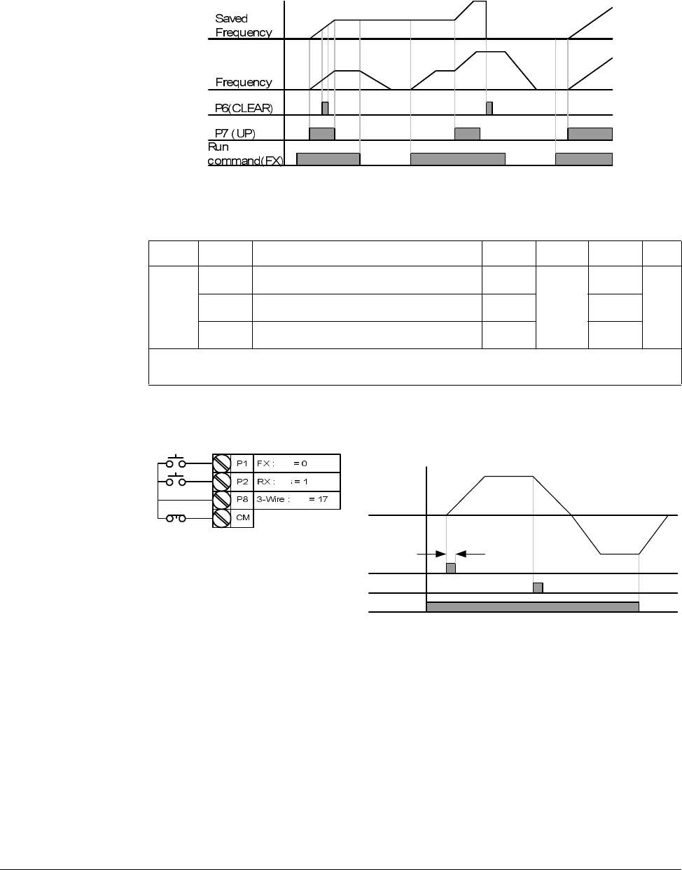
Customizing for Your Application 8-9
If
‘Up/Down Save Frequency Initialization’ signal is input while the multi-function input
‘Up’ or ‘Down’ function is applied, this signal is ignored.
8.3 3-Wire
Input signal is saved in 3-Wire operation. Therefore, inverter can be operated by
Push-button switch.
The bandwidth of pulse (t) should not be less than 50msec.
Group Display Parameter Name Setting Range Default Unit
I/O
group
t1 [Multi-function Input Terminal P1 Selection] 0
0 to 24
0
to to
t8 [Multi-function Input Terminal P8 Selection] 17 7
Select the terminal from P1-P8 for use as 3-Wire operation.
If P8 is selected, set I24 to “17” [3-Wire operation].
FX
RX
Frequency
P8 (3-Wire)
t
t1
t2
t8

8-10 VS1-MD AC Drive User Manual
8.4 PID Control
H50: Select the feedback type of PID controller.
H51: Set the percentage of output to error. If P Gain is set to 50%, 50% of the error
value will be output. Higher value can reach the target control value faster but it may
cause oscillation.
H52: Set the time to output the accumulated error value. Set the time required to
output 100% when the error value is 100%. If H52 [Integral time for PID controller (I
gain)] is set to 1 sec and the error becomes 100%, 100% will be output in 1 sec.
Adjusting the value may reduce the nominal error. If the value is reduced, response
will be faster but setting too low may lead to controller oscillation.
H53: Set the output value to the variation of the error. The error is detected by 0.01
sec in SV-iG5A. If differential time is set to 0.01 sec and the percentage variation of
error per 1 sec is 100%, 1% per 10msec is output.
H54: PID Feed Forward Gain. Set the gain to add the target value to the PID controller
output.
H55, H56: Limits the output of the PID controller.
I17 to I24: To go from PID to normal operation, set one of P1-P8 terminal to 21 and
turn ON.
d1: Calculates the feedback from H50 into Motor frequency and displays it.
Group Display Parameter Name Setting Range Default Unit
Function
group 2
H40 [Control Mode Selection] 2 0 to 3 0 -
H50 [PID Feedback Selection] - 0 to 1 0 -
H51 [P Gain for PID Controller] - 0 to 999.9 300.0 %
H52 [I Gain for PID Controller] - 0.1 to 32.0 1.0 sec
H53 [D Gain for PID Controller] - 0.0 to 30.0 0 sec
H54 [F Gain for PID Controller] 0 to 999.9 0 %
H55 [PID Output Frequency High Limit] - 0.1 to 400 60.0 Hz
H56 [PID Output Frequency Low Limit] - 0.1 to 400 0.50 Hz
I/O group t1 to t8 [Multi-function Input Terminal
P1-P8 Definition] 21 0 to 25 - -
Drive group d1 [Motor RPM]
Set H40 to “2” [PID Feedback control].
Output frequency of the inverter is controlled by PID control for use as constant control of flow, pressure or
temperature.
H50 [PID Feedback Selection] 0 Terminal I input (0 to 20[mA] )
1 Terminal V1 input (0 to 10[V])
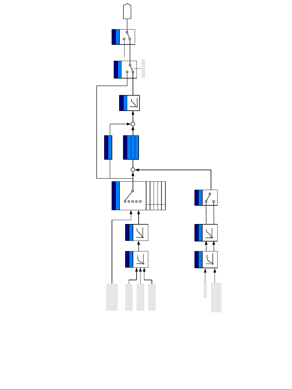
Customizing for Your Application 8-11
r G Y
}X X a T X W ¥ RX W }
}XYGaGWG¥GXW}
pGaGWG¥GYWh
Drive group
P40
Func. group 2
H51 : P gain
yG
wpkG
I/O group
t40 t45
hGG
I/O group
t36~ t49
hGG
X
Y
Z
[
r G XW
Func.
group 2
H40
jGG
Y
P1 ~ P8
Ac c e l/
Decel
W
X
Y
Z
[
I/ O g rou p
t40, t45
hGG hGG
V1_2
: 0 ~ 10V
I
Func.
group 2
H50
m G
W
X
R
I/O group
t41~ t49
T
H52 : I time
H53 : D time
Func. group 2
H54
mGmGn
R
R
I/O group
t1 ~ t8
wpTjG
i
Func.
group 2
H55
wpkGGUG
WSGXSGZ
V1
0~+10[V]
Keypad/
Remote
keypad
V1
-10 ~ +10
[V]
I
0~20[mA]
PID Block Diagram
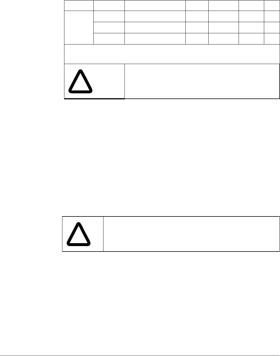
8-12 VS1-MD AC Drive User Manual
8.5 Auto-tuning
H41: When H41 is set to 1 and press the Enter (ò) key, Auto tuning is activated and
“TUn” will appear on the LED keypad. When finished, “H41” will be displayed.
H42, H44: The values of motor stator resistance and leakage inductance detected in
H41 are displayed, respectively. When Auto tuning is skipped or H93 – [Parameter
initialize] is done, the default value corresponding to motor type (H30) will be
displayed.
Press the STOP/RST key on the keypad or turn on the EST terminal to stop the Auto
Tuning.
If Auto tuning of H42 and H44 is interrupted, the default value will be set. If H42 and
H44 are finished and auto-tuning of leakage inductance is interrupted, the measured
value of H42 and H44 are used and the default of leakage inductance is set.
See page for motor parameter default values.
Group Display Parameter Name Setting Range Default Unit
H-
Function
group 2
H41 [Auto Tuning] 1 0 to 1 0 -
H42 [Stator Resistance (Rs)] - 0 to 28 - W
H44 [Leakage Inductance (Lσ)] - 0 to 300.00 - mH
Motor parameters will be automatically measured.
The measured motor parameters in H41 can be used in Auto Torque Boost and Sensorless Vector
Control.
!
ATTENTION:Auto tuning should only be executed after
motor has stopped. Motor shaft must not run by the load
during H41[Auto tuning].
!
ATTENTION:Be sure accurate values are entered for stator
resistance and leakage inductance. Otherwise, the performance
of Sensorless vector control and Auto torque boost could be
compromised.
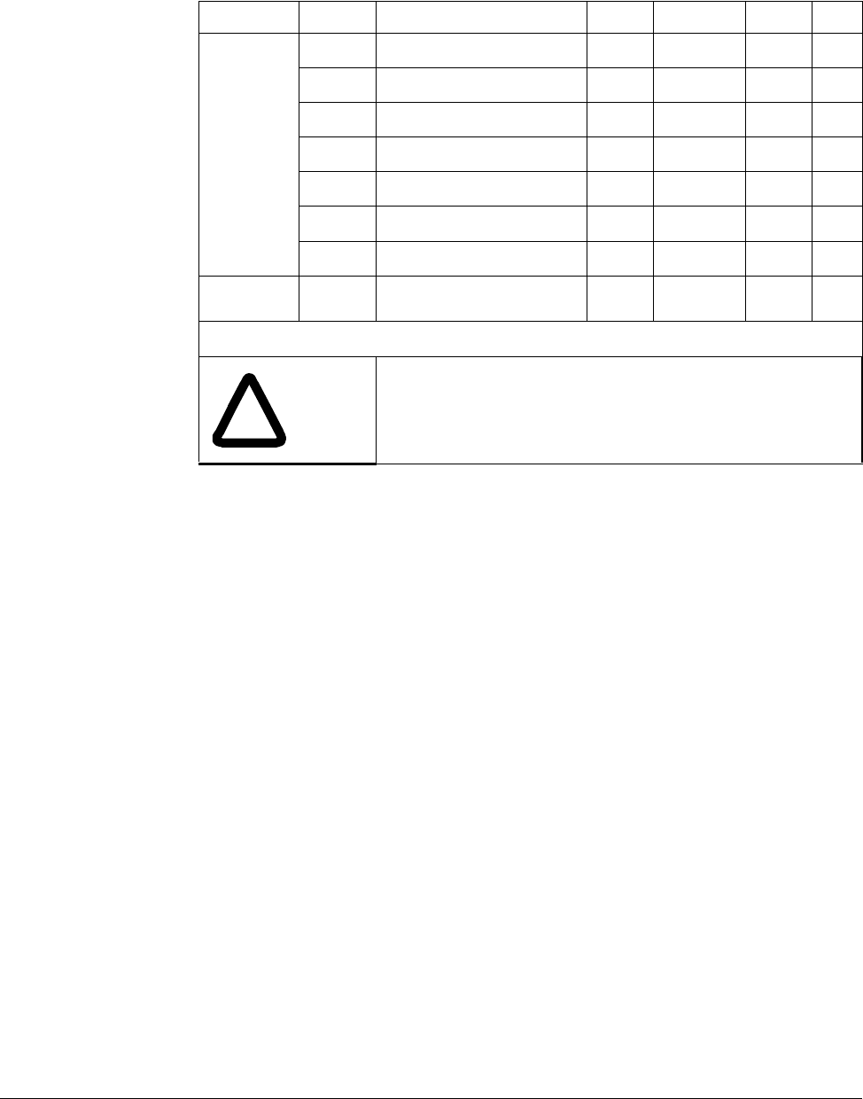
Customizing for Your Application 8-13
8.6 Sensorless Vector Control
Ensure that the following parameters are entered correctly for optimal performance in
Sensorless vector control.
P30: Select motor type connected to inverter output.
H32: Enter rated slip frequency based on motor nameplate RPM and rated frequency
(See 10-6).
P32: Enter motor nameplate rated current.
H34: After removing the load, set H40[Control mode Selection] to “0” [V/F control] and
run the motor at 60Hz. Enter the current displayed in Cur-[Output current] as motor no
load current. If it is difficult to remove the load from the motor shaft, enter a value
equal to 40 to 50% of H33[Motor rated current] or the factory default.
H42, H44: Enter the value of the parameter measured during H41[Auto tuning] or the
factory default.
F14: This parameter accelerates the motor after pre-exciting the motor for the set
time. The amount of the pre-exciting current is set in H34[Motor No Load Current].
Directly enter the motor nameplate value except motor rating when 0.2kW is used.
Group Display Parameter Name Setting Range Default Unit
H - Function
group 2
H40 [Control Mode Selection] 3 0 to 3 0 -
P30 [Motor Type Selection] - 0.2 to 7.5 - kW
H32 [Rated Slip Frequency] - 0 to 10 - Hz
P32 [Motor Rated Current] - 0.5 to 50 - A
H34 [Motor No Load Current] - 0.1 to 20 - A
H42 [Stator Resistance (Rs)] - 0 to 14 - W
H44 [Leakage Inductance (Lσ)] - 0 to 300.00 - mH
Function
group 1 F14 [Time for Energizing a Motor] - 0.0 to 60.0 0.1 sec
If H40[Control mode Selection] is set to “3”, Sensorless vector control will become active.
!
ATTENTION:Motor parameters should be measured for
optimal performance. It is highly recommended H41 [Auto
tuning] be done prior to operating via Sensorless vector
control.

8-14 VS1-MD AC Drive User Manual
Factory default by motor ratings
Input
voltage
Motor
rating
[kW]
Current
rating
[A]
No-load
current
[A]
Rated slip
freq
[Hz]
Stator
resistance
[Ω]
Leakage
inductance
[mH]
200
0.2 1.1 0.6 2.33 14.0 122.00
0.4 1.8 1.2 3.00 6.70 61.00
0.75 3.5 2.1 2.33 2.46 28.14
1.5 6.5 3.5 2.33 1.13 14.75
2.2 8.8 4.4 2.00 0.869 11.31
3.7 12.9 4.9 2.33 0.500 5.41
5.5 19.7 6.6 2.33 0.314 3.60
7.5 26.3 9.0 2.33 0.169 2.89
400
0.2 0.7 0.4 2.33 28.00 300.00
0.4 1.1 0.7 3.0 14.0 177.86
0.75 2.0 1.3 2.33 7.38 88.44
1.5 3.7 2.1 2.33 3.39 44.31
2.2 5.1 2.6 2.00 2.607 34.21
3.7 6.5 3.3 2.33 1.500 16.23
5.5 9.9 3.9 2.33 0.940 10.74
7.5 15.2 5.7 2.33 0.520 8.80
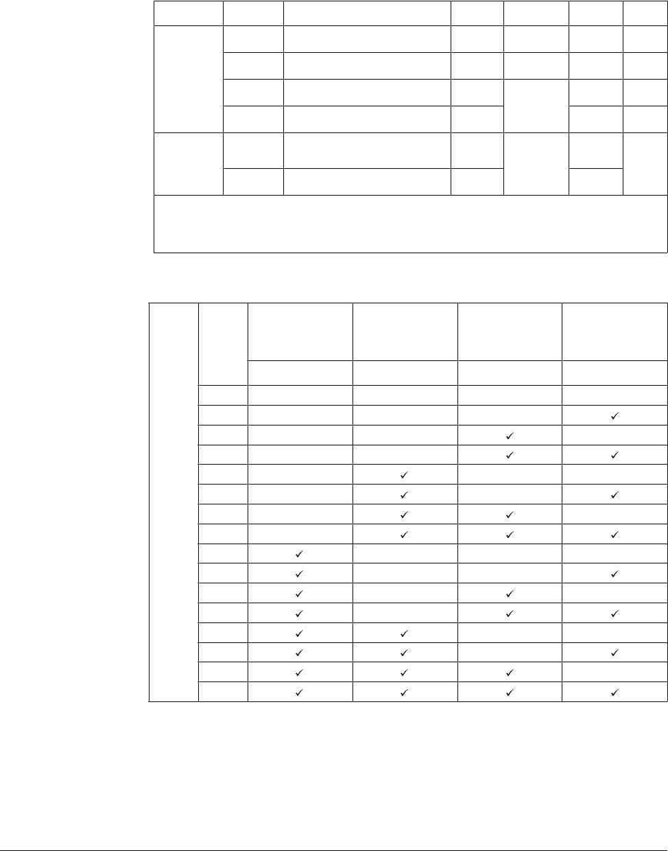
Customizing for Your Application 8-15
8.7 Speed Search
The following table shows 4 types of Speed search selections.
H23: Limits current during Speed search. Set as a percentage of H33.
H24, H25: Speed search is activated via PI control. Adjust P gain and I gain
corresponding to the load characteristics.
t32, t33: Signal of active Speed search is given to external sequence via Multi-function
output terminal (MO) and Multi-function relay output (3ABC).
Group Display Parameter Name Setting Range Default Unit
Function
group 2
H22 [Speed Search Selection] - 0 to 15 0
H23 [Current Level] - 80 to 200 100 %
H24 [Speed Search P Gain] -
0 to 9999
100
H25 [Speed Search I Gain] - 200
I/O group
t32 [Multi-function Output
Terminal Selection] 15
0 to 18
12
t33 [Multi-function Relay Selection] 15 17
This is used to prevent possible faults from occurring if the inverter outputs the voltage during operation
after the load is removed.
The inverter estimates the motor rpm based on output current. Therefore, detecting exact speed is
difficult.
H22
Speed Search
During
H20[Power ON
Start]
Speed Search
During Instant
Power Failure
Restart
Speed Search
During
H21[Restart After
Fault Reset]
Speed Search
During
Acceleration
Bit 3Bit 2Bit 1Bit 0
0- - - -
1- - -
2- - -
3- -
4- --
5- -
6- -
7-
8---
9--
10 - -
11 -
12 --
13 -
14 -
15
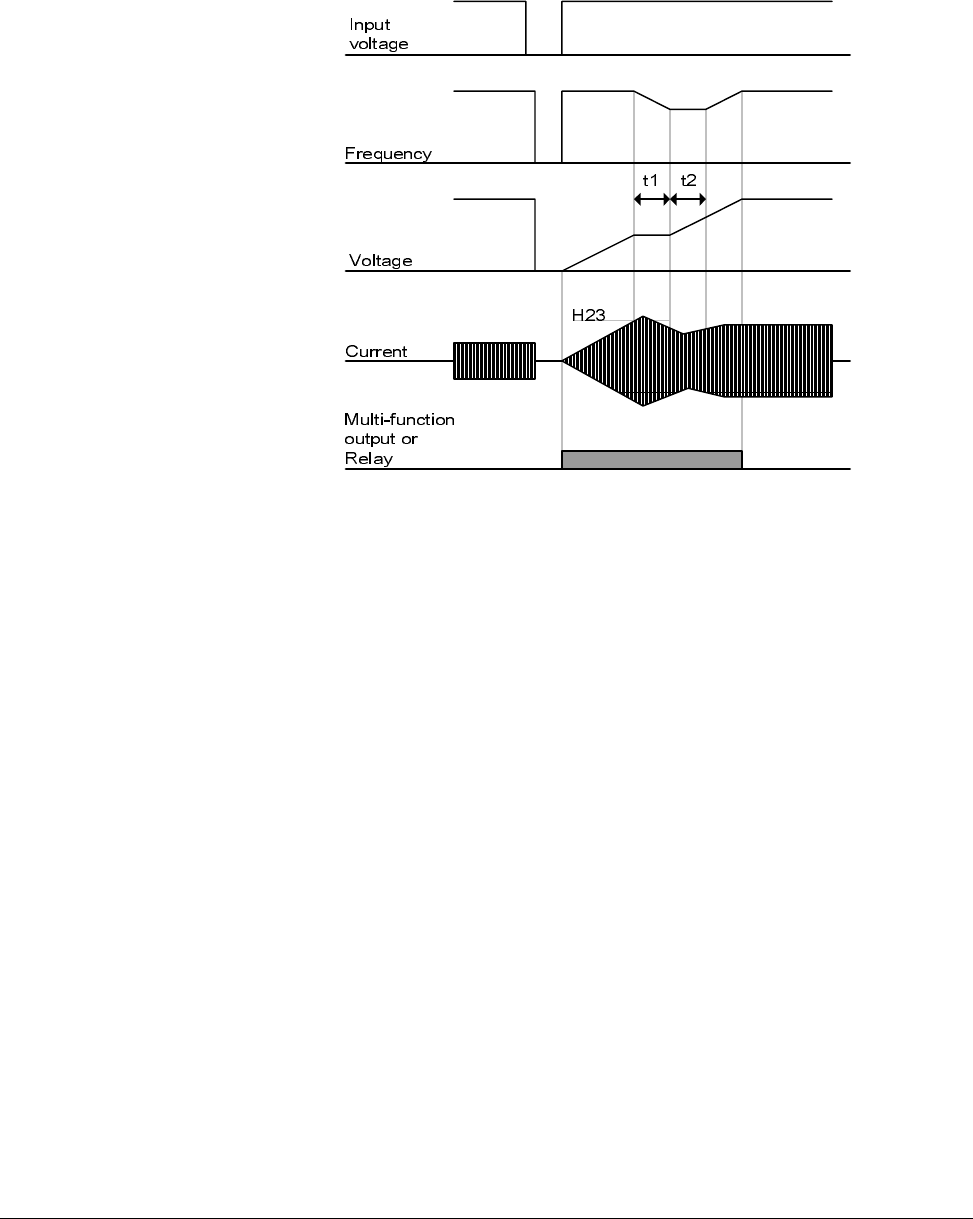
8-16 VS1-MD AC Drive User Manual
Example
Speed search during Instant Power Failure restart
Speed search operation is suitable for loads with high inertia. Stop the motor and
restart when friction in load is high.
VS1MD keeps normal operation when instant power failure occurs and power is
restored in 15msec for the use of its inverter rating.
Inverter DC link voltage can vary depending on output load quantity. Therefore, Low
Voltage trip may occur when instant power failure is maintained over 15msec or output
is higher than its rating.
Instant power failure specification is applied when input voltage to Inverter is 200 to
230V AC for 200V class, or 380 to 480V AC for 400V class.
•When the input power is cut off due to instant power failure, the
inverter outputs Low voltage trip (LV) to hold the output.
•When the power is restored, the inverter outputs the frequency
before the low voltage trip and the voltage is increased due to PI
control.
•t1: If current is increasing over the preset level in H23, the rise in
voltage will stop and the frequency is decreased.
•t2: If the opposite of t1 occurs, the increase in voltage starts again
and the decrease in frequency stops.
•When the frequency and voltage are restored back to the nominal
level, acceleration will continue at the frequency before trip.
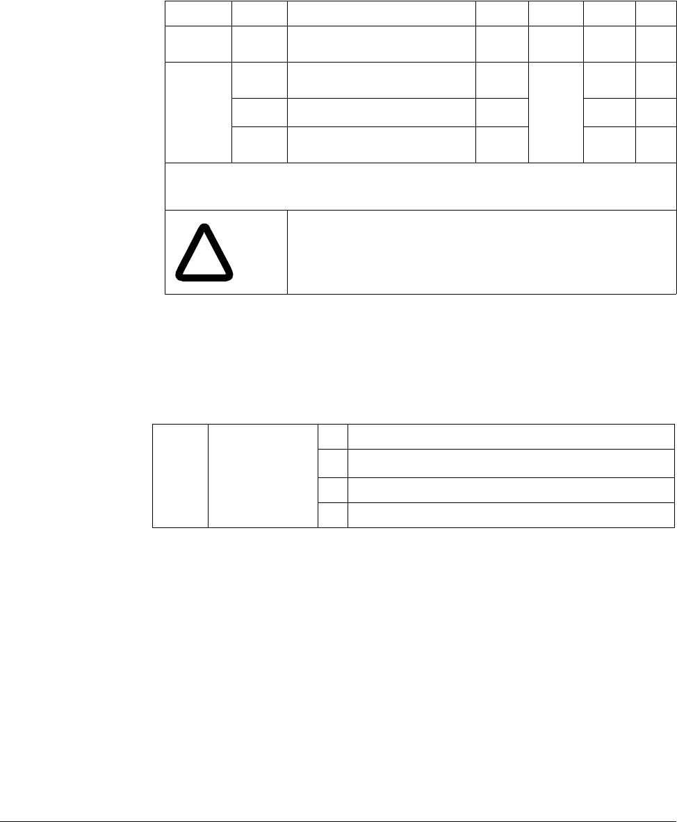
Customizing for Your Application 8-17
8.8 Self-Diagnostic Function
8.8.1 How to Use Self-Diagnostic Function
Perform Self-diagnostic function after input/output wiring of the inverter is finished.
This function allows the user to safely check for the IGBT fault, output phase open and
short, and Ground fault without disconnecting the inverter wiring.
There are 4 options:
Once H60 is set to a specific value from 1 to 3 and the terminal defined for this
function among P1 to P8 terminals is turned ON, the corresponding function is
conducted, displaying “dIAG”
To stop this function, press STOP/RESET key on the keypad, turn the defined terminal
OFF or turn the EST terminal ON.
Group Display Parameter Name Setting Range Default Unit
Function
group 2 H60 Self-Diagnostic Selection - 0 to 3 0 -
I/O group
t1 Multi-function Input Terminal P1
Selection -
0 to 25
0-
to to
t8 Multi-function Input Terminal P8
Selection 20 7 -
Select Self-Diagnostic function in H60, Function group 2.
Define one terminal among P1toP8 terminals for this function.
To define P8 for this function, set t8 to “20”.
!
ATTENTION:Do not touch the inverter with hands or other
objects while performing this function because current is
flowing to the inverter output.
H601
1Selecting the higher number performs all functions within lower numbers.
Self-Diagnostic
function
0 Self-Diagnostic disabled
1IGBT fault and Ground fault2
2Ground fault of U phase in 2.2KW to 4.0KW inverters and ground fault of
V phase in other rating inverters may not be detected when selecting “1”.
Select 3 to make sure to detect all phase of U, V, W
2 Output phase short & open circuit and Ground fault
3 Ground fault (IGBT fault, Output phase short and open circuit)
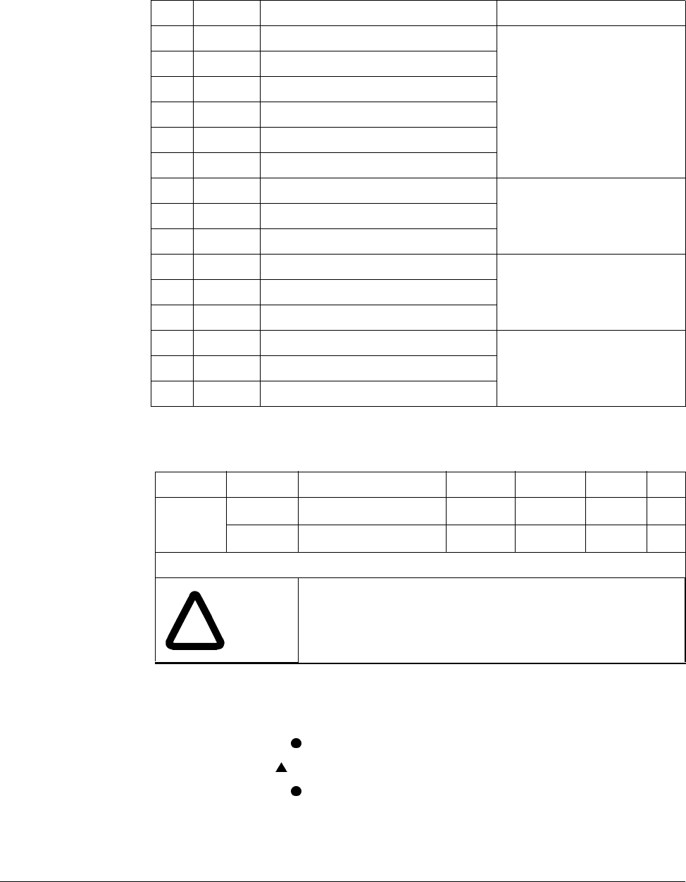
8-18 VS1-MD AC Drive User Manual
The following table shows the fault type while this function is active.
8.9 Parameter Read/Write
8.9.1 Parameter Read
Step 1. Move to H91 code.
Step 2. Press Enter ( ) key once. 0 will be displayed.
Step 3. Press Up ( ) key once. Rd will be displayed.
Step 4. Press Enter ( ) key twice. Rd will be displayed
Step 5. H91 is displayed when Parameter read is finished.
No. Display Fault type Diagnosis
1 UPHF Switch above IGBT’s U phase fault
Contact sales representatives.
2 UPLF Switch below IGBT’s U phase fault
3 vPHF Switch above IGBT’s V phase fault
4 vPLF Switch below IGBT’s V phase fault
5 WPHF Switch above IGBT’s W phase fault
6 WPLF Switch below IGBT’s U phase fault
7 UWSF Output short between U and W Check for a short in inverter output
terminal, motor connection
terminal or the proper motor
connection.
8 vUSF Output short between U and V
9 WvSF Output short between V and W
10 UPGF Ground fault at U phase
Check for ground fault occurring at
inverter output cable or motor or
motor insulation damage.
11 vPGF Ground fault at V phase
12 WPGF Ground fault at W phase
13 UPOF Output open at U phase
Check for proper connection of the
motor to the inverter output or
proper motor connection.
14 vPOF Output open at V phase
15 WPOF Output open at W phase
Group Display Parameter Name Setting Range Default Unit
Function
group 2
H91 [Parameter Read] 1 0 to 1 0
H92 [Parameter Write] 1 0 to 1 0
Used to read/write Inverter Parameters using remote keypad.
!
ATTENTION:Take caution when Parameter write (H92) is
executed. By doing this, parameters in inverter are cleared
and parameters in remote keypad are copied to inverter.
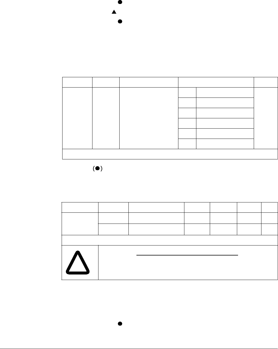
Customizing for Your Application 8-19
8.9.2 Parameter Write
Step 1. Move to H92 code. H92 will be displayed.
Step 2. Press Enter ( ) key once. 0 will be displayed.
Step 3. Press Up ( ) key once. Wr will be displayed.
Step 4. Press Enter ( ) key twice. Wr will be displayed.
Step 5. H91 is displayed when Parameter read is finished.
8.10 Parameter Initialization / Lock
8.10.1 Parameter Initialization
Press Enter key after setting in H93. H93 will be displayed again after initialization
is complete.
8.10.2 Password Registration
Factory default password is 0. Enter any new password except 0.
8.10.2.1 Registering the password for the first time.
Step 1. Move to H94 code. H94 will be displayed.
Step 2. Press Enter ( ) key twice. 0 will be displayed.
Step 3. Register password. (Ex: 123) 123 will be displayed.
Group Display Parameter Name Range Default
Function
group 2 H93 [Parameter Initialization]
0-
0
1 Initialize All Groups
2 Initialize Drive Group
3 Initialize F 1 Group
4 Initialize F 2 Group
5 Initialize I/O group
Select the group to be initialized and perform it in H93 code.
Group Display Parameter Name Setting Range Default Unit
Function
group 2
H94 [Password Registration] - 0 to FFFF 0
H95 [Parameter Lock] - 0 to FFFF 0
Register password for Parameter lock (H95). Password should be Hex decimal. (0 to 9, A, B, C, D, E, F)
!
ATTENTION:Do not forget the registered password. It is needed
to unlock parameters.
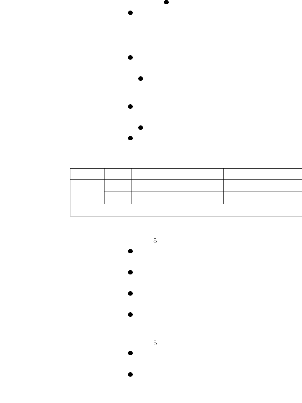
8-20 VS1-MD AC Drive User Manual
Step 4. 123 will blink when Enter ( ) key is pressed. 123 will be displayed.
Step 5. Press Enter ( ) key. H94 will be displayed after the new password has been
registered.
8.10.2.2 Changing password. (Current PW: 123 -> New PW: 456)
Step 1. Move to H94 code. H94 will be displayed.
Step 2. Press Enter ( ) key. 0 will be displayed.
Step 3. Enter any number (e.g.: 122). 122 will be displayed.
Step 4. Press the Enter ( ) key. 0 is displayed because wrong value was entered.
Password cannot be changed in this status. 0 will be displayed.
Step 5. Enter the right password. 123 will be displayed.
Step 6. Press Enter ( ) key. 123 will be displayed.
Step 7. Enter the new password. (e.g. 456). 456 will be displayed.
Step 8. Press the Enter ( ) key. Then “456” will blink. 456 will be displayed.
Step 9. Press Enter ( ) key. H94 will be displayed.
8.10.3 Parameter Lock
8.10.3.1 Locking the user-set parameters.
Step 1. Move to H95 code. H9 will be displayed.
Step 2. Press Enter ( ) key. UL will be displayed.
Step 3. Parameter value can be changed in UL (Unlock) status. UL will be displayed.
Step 4. Press Enter ( ) key. 0 will be displayed.
Step 5. Enter the password created in H94 (e.g.: 123). 123 will be displayed.
Step 6. Press Enter ( ) key. L will be displayed.
Step 7. Parameter value cannot be changed in L (Lock) status. L will be displayed.
Step 8. Press Enter ( ) key. H95 will be displayed.
8.10.3.2 Unlocking the user-set parameter.
Step 1. Move to H95 code. H9 will be displayed.
Step 2. Press Enter ( ) key. L will be displayed.
Step 3. Parameter value cannot be changed in L(Lock) status. L will be displayed.
Step 4. Press Enter ( ) key. 0 will be displayed.
Step 5. Enter the password created in H94 (e.g.: 123). 123 will be displayed.
Group Display Parameter Name Setting Range Default Unit
Function
group 2
H95 [Parameter Lock] - 0 to FFFF 0
H94 [Password Registration] - 0 to FFFF 0
This parameter is used to lock the user-set parameters using the password.
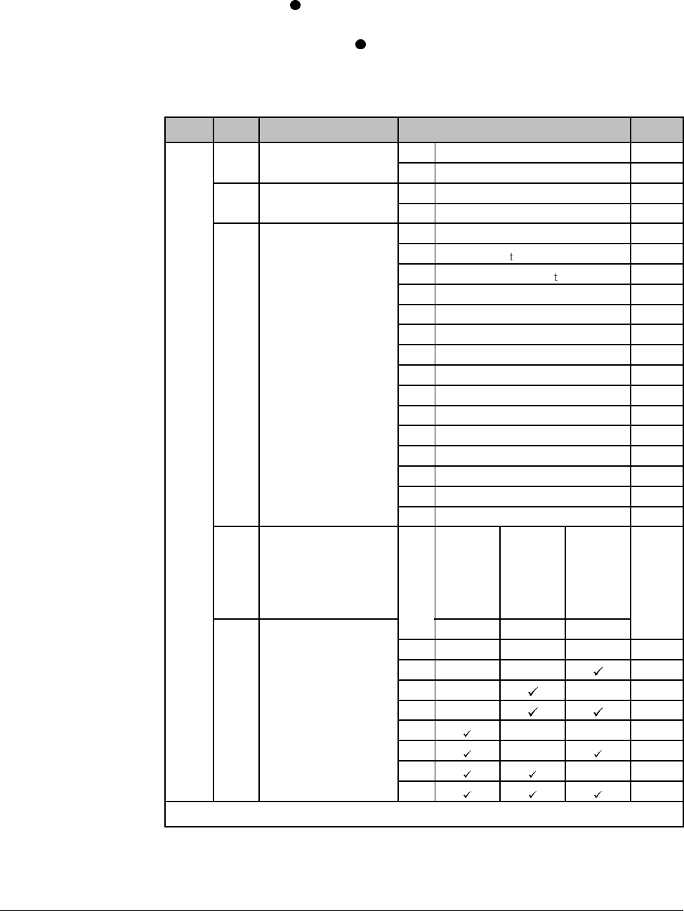
Customizing for Your Application 8-21
Step 6. Press Enter ( ) key. UL will be displayed.
Step 7. Parameter value can be changed in UL (Unlock) status. While UL is
displayed, press Enter ( ) key. H95 will be displayed.
8.11 Multi-function Output Terminal (MO) and Relay (3AC)
t34: When 17 [Fault display] is selected in t32 and t33, Multi-function output terminal
and relay will be activated with the value in t34.
Group Code Parameter Setting range Initial
I/O
group t32 [Multi-function output
terminal Selection] 0FDT-1 12
1FDT-2
t33 [Multi-function relay
Selection] 2FDT-3 17
3FDT-4
4FDT-5
5Overload [OL ]
6Inverter Overload [IOL ]
7 Motor stall [STALL]
8 Over voltage trip [OV]
9 Low voltage trip [LV]
10 Inverter overheat [OH]
11 Command loss
12 During run
13 During stop
14 During constant run
15 During speed searching
16 Wait time for run signal input
17 Fault output
18 Cooling fan trip alarm
t34 [Fault relay output] When
setting
H26
[Number
of auto
restart
tries]
When trip
other
than low
voltage
trip
occurs
When
low
voltage
trip
occurs
Bit 2 Bit 1 Bit 0
0---
2
1--
2- -
3-
4--
5-
6-
7
Select the desired item to be output via MO terminal and relay (30AC).
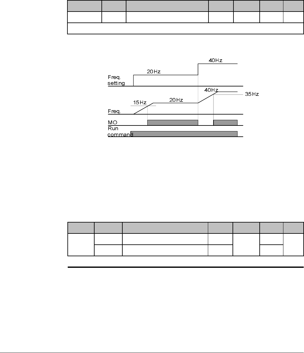
8-22 VS1-MD AC Drive User Manual
8.11.1 FDT-1
Check whether the output frequency matches the user-setting frequency.
Active condition: Absolute value (preset frequency - output frequency) <= Frequency
Detection Bandwidth/2
When setting t31 to 10.0
8.11.2 FDT-2
Activated when the preset frequency matches frequency detection level (t52) and
FDT-1 condition is met.
Active condition: (Preset frequency = FDT level) & FDT-1
Group Display Parameter Name Setting Range Default Unit
I/O group t31 [Detected Frequency Bandwidth] - 0 to 400 10.00 Hz
Cannot be set above Max frequency (P36).
Group Display Parameter Name Setting Range Default Unit
I/O
group
t30 [Detected Frequency level] - 0 to 400 30.00 Hz
t31 [Detected Frequency Bandwidth] - 10.00
Cannot be set above Max frequency (P36).
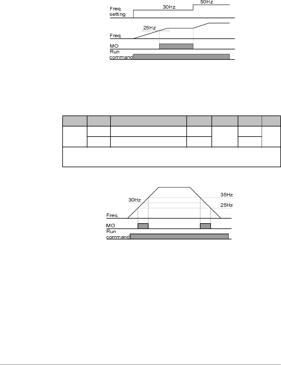
Customizing for Your Application 8-23
When setting t30 and t31 to 30.0 Hz and 10.0 Hz, respectively
8.11.3 FDT-3
Activated when run frequency meets the following condition.
Active condition: Absolute value (FDT level - run frequency) <= FDT Bandwidth/2
When setting t30 and t31 to 30.0Hz and 10.0 Hz, respectively
8.11.4 FDT-4
Activated when run frequency meets the following condition.
Active condition:
Accel time: Run Frequency >= FDT Level
Group Display Parameter Name Setting Range Default Unit
I/O
group
t30 [Detected Frequency level] - 0 to 400 30.00 Hz
t31 [Detected Frequency Bandwidth] - 10.00
Cannot be set above Max frequency (P36).
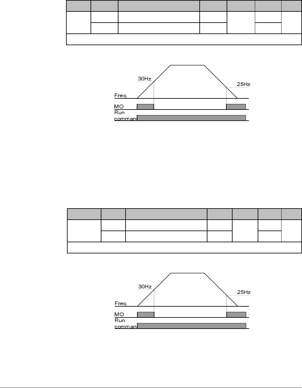
8-24 VS1-MD AC Drive User Manual
Decel time: Run Frequency > (FDT Level – FDT Bandwidth/2)
When setting t30 and t31 to 30.0Hz and 10.0 Hz, respectively
8.11.5 FDT-5
Activated as B contact contrast to FDT-4.
Active condition:
Accel time: Run Frequency >= FDT Level
Decel time: Run Frequency > (FDT Level – FDT Bandwidth/2)
When setting t30 and t31 to 30.0Hz and 10.0 Hz, respectively
8.11.6 Over Voltage Trip (Ovt)
Activated when over voltage trip occurs due to DC link voltage exceeded 460Vdc for
230V class and 820Vdc for 460V class.
Group Display Parameter Name Setting Range Default Unit
I/O
group
t30 [Detected Frequency level] - 0 to 400 30.00 Hz
t31 [Detected Frequency Bandwidth] - 10.00
Cannot be set above Max frequency (P36).
Group Display Parameter Name Setting Range Default Unit
I/O group t30 [Detected Frequency level] - 0 to 400 30.00 Hz
t31 [Detected Frequency Bandwidth] - 10.00
Cannot be set above Max frequency (P36).
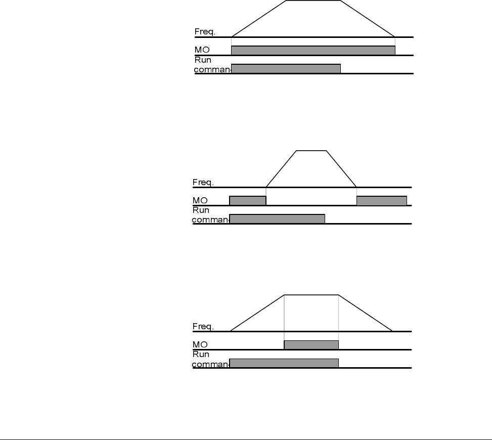
Customizing for Your Application 8-25
8.11.7 Low Voltage Trip (Lvt)
Activated when low voltage trip occurs due to DC link voltage under 180Vdc for 200V
class and 360Vdc for 400V class.
8.11.8 Inverter Heatsink Overheat (OHt)
Activated when the heatsink is overheated.
8.11.9 Command Loss
Activated when Analog (V1,I) and RS485 communication commands are lost.
8.11.10 During Operation
Activated when run command is input and inverter outputs its voltage.
8.11.11 During Stop
Activated during stop without active command.
8.11.12 During Constant Run
Activated during constant speed operation.

8-26 VS1-MD AC Drive User Manual
8.11.13 Wait Time for Run Signal Input
This function becomes active during normal operation and that the inverter waits for
active run command from external sequence.
8.11.14 Fault Output
The parameter set in t34 is activated.
For example, if setting t33, t34 to 17 and 2, respectively, Multi-function output relay will
become active when trip other than “Low voltage trip” occurred.
8.11.15 Cooling Fan Trip Alarm
Used to output alarm signal when H78 is set to ”0”(constant operation at cooling fan
trip).
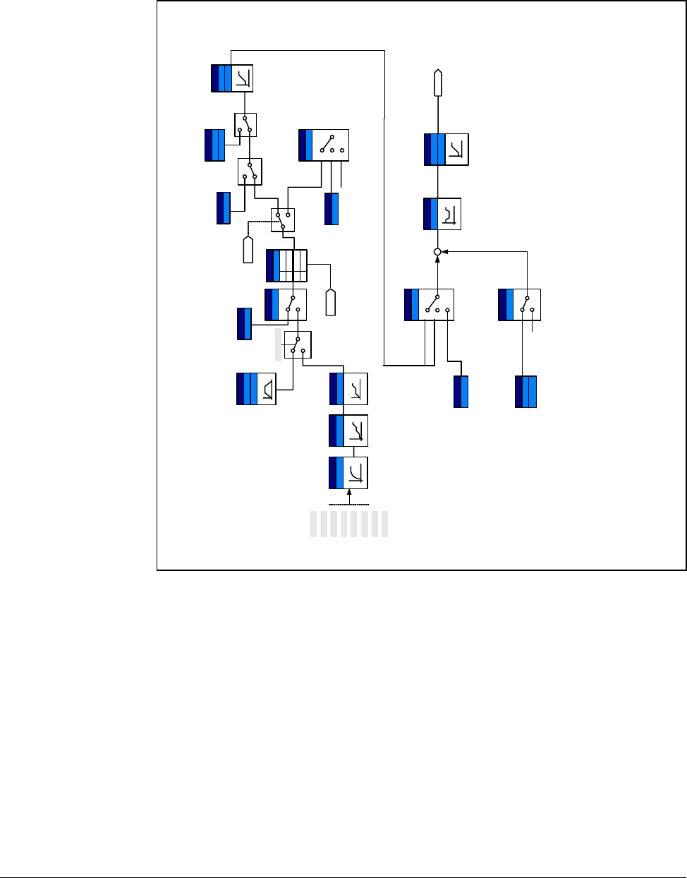
Customizing for Your Application 8-27
8.12 Accel/Decel setting and V/F Control
Reference freq. for
Accel/Decel
Accel/Decel
time
P1
P2
P3
P4
P5
Digital input filter Multi-Accel/Decel
time select
5,6,7
P1 ~ P8
Max freq.
0
1
Accel/Decel
pattern
S-curve1
Linear
0
Stop method select
0
1
2
DC brake
FreeRun Stop
DC brake freq.
voltage, time
DC brake start freq.
Func. group1
H7
Dwell operation
H8
I/O group
F25
Freq. high/low limit
F26
0
1~7
Run
command
DC brake voltage
&time
Dwell freq. & time
V/F pattern
0
1
2
Square
User V/F
Freq., Voltage
Torque boost
select
Torque
boost value
0
1
Autom atic
Manual
Linear
User V/F
Output voltage
adjustment
+
Base/start freq.
PWM
Operation
Stop
Frequency
setting
Func. group1
F8 ~ F11
Func. group1
F4
Func. group1
F2, F3
Func. group1
H70
Func. group1
F21
Drive group
ACC
DEC
1st-7th Accel/
Decel time
I/O group
t34 ~ I47
I/O group
t17 ~ I 2 4
I/O group
t27
Func. group1
F8 ~ F11
I/O group
F22
F23
I/O group
F39
Func. group 1
F30
Func. group 1
F27
Func. group 1
F31~F38
Func. group 1
F28
F29
P6
P7
P8
Optimal time
1
Shortes t time
0
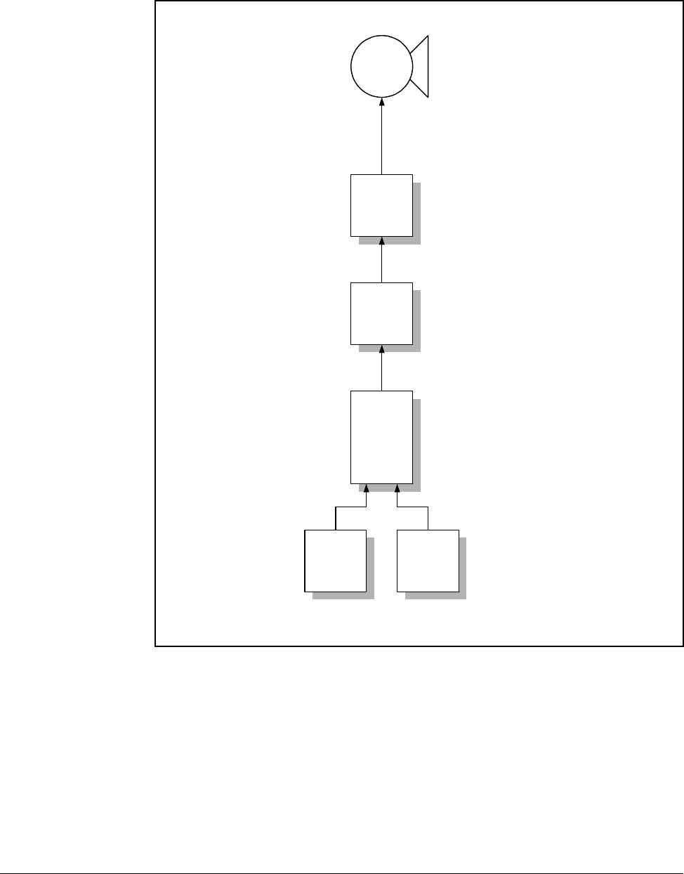
8-28 VS1-MD AC Drive User Manual
8.13 Control Block Diagram
mG
kG
hVk }Vm
w~t t

Customizing for Your Application 8-29
8.14 Frequency and Drive Mode Setting
Keypad setting 2
V1_1:-10 ~ 10V
V1_2 : 0 ~ 10V
I:0~20mA
V1_1 + I
V1_2 + I
Drive group
P40
Drive group
St1
St2
St3
I/O group
t10
t11
t12
t13
Zero
speed
I/O group
t1 ~ t8
Speed
1~7
Freq. setting
method
Multi-step freq.
setting
Multi-step operation
select
I/O group
t40, t45
Analog in put filter
I/O g rou p
t36-t49
Analog input scale
Analog input
override
I/O group
t9
Digital input filter
+1
2
3
4
5
6
7
Keypad setting 10
V1
0~+10[V]
P1
P2
P3
P4
P5
Keypad or
Remote
keypad
I/O g rou p
t1 ~ t8
FWD/REV Run command
select for Multi-function
terminals
I/O group
t1 ~ t8
3-Wire
operation
Function group 1
F1
FWD/REV rotation
disable
5,6,7
0,1
17
Drive
group
drv
Run/Stop command
select
0
1
2
Keypad
1,2
FWD run Disable
REV r un disable
1
2
no selection0
I/O g rou p
t1 ~ t8
Up-Down
operation
I/O group
t1 - t8
Jog operation
Function
group 1
F21
F23
Min/Max freq.
15, 16
Function
group 1
F20
Jog freq.
4
P1 ~ P8
Set freq.
Run/Stop
command
0
1
2
3
4
5
6
7
Communication
V1
-10 ~ +10 [V]
I
0~20[mA]
P6
P7
P8

8-30 VS1-MD AC Drive User Manual
Troubleshooting 9-1
CHAPTER 9
Troubleshooting
The VS1MD constantly monitors its status and provides the following ways to
determine the status of the drive and to troubleshoot problems that may occur:
•LEDS on the drive
•Fault Codes displayed on seven segment display
•Drive monitor and status parameters
•Entries in the fault queue
9.1 Verifying that DC Bus Capacitors are Discharged
Before Servicing the Drive
The drive’s DC bus capacitors retain hazardous voltages after input power has been
disconnected. Perform the following steps before touching any internal components:
Step 1. Turn off and lock out input power. Wait 10 minutes after drive’s 7-segment
display goes blank.
Step 2. Open the drive’s cover.
Step 3. Verify that there is no voltage at the drive’s input power terminals.
Step 4. Once the drive has been serviced, reattach the drive’s cover.
Step 5. Reapply input power to the drive.
!
ATTENTION: This drive contains high voltage capacitors that take
time to discharge after removal of mains supply. Before working on the
drive, ensure isolation of mains supply from line inputs. Wait ten (10)
minutes for capacitors to discharge to safe voltage levels. Failure to
observe this precaution could result in severe bodily injury or loss of life.
ATTENTION: Only qualified electical personnel familiar with the
construction and operation of this equipment and the hazards involved
should install, adjust, operate, or service this equipment. Read and
understand this manual and other applicable manuals in their entirety
before proceeding. Failure to observe this precaution could result in
severe bodily injury or loss of life.
!
ATTENTION: DC Bus capacitors retain hazardous voltages after input
power has been disconnected. After disconnectiong input power, wait ten
(10) minutes for the DC Bus capacitors to discharge and then check the
voltage with a voltmeter to ensure the DC bus capacitors are discharged
before touching any internal components. Failure to observe this
precaution could result in severe bodily injury or loss of life.

9-2 VS1-MD AC Drive User Manual
9.2 Determining Drive Status Using the STP/FLT LED
The STP/FLT LED can be used to determine at a quick glance the status of the drive.
If the drive is stopped, but not faulted, this LED will be illuminated solid. If the drive is
running, this LED will be off. If this LED is flashing, then this indicates that the drive is
faulted thus requiring attention. Please refer to figure 9.1.
9.3 Monitoring Drive Status Using the Display
Parameters
The Display Group has multiple parameters that can be utilized for monitoring the
status of the drive and are useful for diagnosing certain situations. Chapter 6
describes how to display these parameters.
If the drive is being operated from the terminal strip, it is useful to monitor the status of
the digital inputs to determine operational problems. The digital input status can be
monitored by displaying parameter d7. The below describes the details of
understanding the status of each of the digital inputs (labeled P1 ~ P8 on the control
board terminal strip). In this example, P1, P3, and P4 are “ON” and P2, P5, P6, P7,
and P8 are “OFF”.
(ON
)
(OFF
)
P8 P7 P6 P5 P4 P3 P2 P1

Troubleshooting 9-3
If the application is using digital outputs to reflect the internal status of the drive, these
can be monitored using parameter d8. The below describes the details of
understanding the status of each of the digital outputs (labeled MO for the open
collector output and 3A/3B/3C for the relay output on the control board terminal strip).
In this example, the multi-function output MO is “ON” and the multi-function relay is
“OFF” (note that the indication for the multi-function relay is an indication of whether or
not the relay coil is energized).
9.4 Reviewing Fault Status of the Drive
As noted in Chapter 6, the Display Group has an entry that designates if there is an
active fault and will display the fault code associated with that fault. The fault codes
are described later in this chapter. While displaying the fault code within the Display
Group, you can press the enter key to display the frequency the drive was running at
when the fault occurred. By pressing the up arrow one time, you can display the
current the drive detected when the fault occurred. By pressing the up arrow again,
you will display the drive status when the fault occurred.
Function Group 2 (H parameters) also contains the current fault along with a history of
the previous 4 faults. These faults are located at parameters H1, H2, H3, H4, and H5.
As with the fault memory in the Display Group, you can subsequently display the
frequency, current, and status for each of these faults using the same procedure
outlined in Chapter 6.
9.5 Fault Codes
Fault codes indicate conditions within the drive that require immediate attention. The
drive responds to a fault by initiating a coast-to-stop sequence and turning off the
power to the motor.
The integral keypad provides visual notification of a fault condition by displaying the
following:
•Fault code on the display. (See table 9.1 for the fault code descriptions.)
•Flashing STP/FLT LED
(ON
)
(OFF
)
MO3A/3B

9-4 VS1-MD AC Drive User Manual
9.5.1 Manually Clearing Faults
Step 1. Note the code of the fault condition on the display.
Step 2. Address the condition that caused the fault. Refer to table 9.1 for a
description of the fault and corrective actions. The cause must be corrected
before the fault can be cleared.
Step 3. After corrective action has been taken, clear the fault and reset the drive.
9.5.2 Automatically Clearing Faults (Auto Restart Feature)
The Auto Restart feature provides the ability for the drive to automatically perform a
fault reset followed by a start attempt without user or application intervention. This
allows remote operation. This feature can only be used for faults that are
auto-resettable.
When this type of fault occurs, and H26 (Auto Restart) is set to a value greater than 0,
a user-configurable timer, H27 (Retry Delay) begins. When the timer reaches zero, the
drive attempts to automatically reset the fault. If the condition that caused the fault is
no longer present, the fault will be reset and the drive will be restarted.
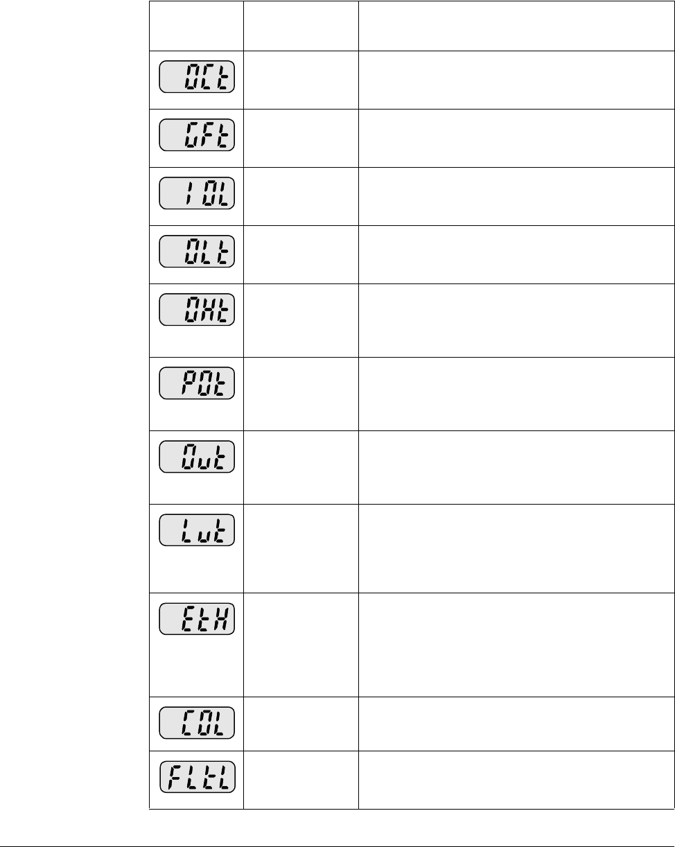
Troubleshooting 9-5
9.5.3 Fault Descriptions
Table 9.1 – Fault Descriptions
Fault Code/
Display Fault Descriptions
Overcurrent The drive diables when the output current is
detected at a level higher than the inverter rated
current.
Ground fault
current The drive disables when a ground fault occurs
and the ground fault current is greater than the
internal setting value of the inverter.
Inverter
Overload The drive disables its output when the output
current of the inverter is greater than the rated
level.
Overload trip The drive disables if the output current of the
inverter is at 150% of the inverter rated current
for more than the current limit time (1 min).
Inverter
overheat The drive disables if the heat sink overheats due
to a damaged cooling fan or a blockage in the
cooling fan by detecting the temperature of the
heat sink.
Output Phase
loss The drive disables its output when one or more
of the output (U, V, W) phases is open. The drive
detects the output current to check the output
phase loss.
Over voltage The drive disables its output if the DC bus
voltage increases above the bus overvoltage
threshold. This fault can also occur due to a
surge voltage generated at the input terminals.
Low voltage The drive disables its output if the DC bus
voltage is less than the undervoltage threshold
because insufficient torque or overheating of the
motor can occur when the input voltage of the
drive is too low.
Electronic
Thermal The internal electronic thermal of the drive
determines the motor heat. If the motor is
overloaded the inverter disables the output. The
drive cannot protect the motor when controlling a
motor having more than 4 poles or multiple
motors.
Input phase
loss Drive output is disabled when one of the input
phases (R, S, T) is open.
Self-
diagnostic
malfunction
Displayed when IGBT damage, output phase
short, output phase ground fault or output phase
open occurs.
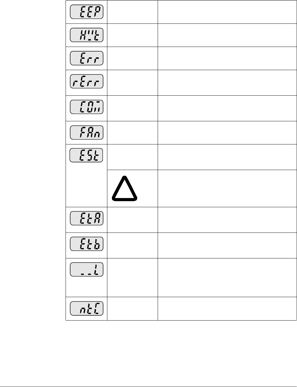
9-6 VS1-MD AC Drive User Manual
Parameter save
error Displayed when user-modified parameters fail to
be stored into memory.
Inverter
hardware fault Displayed when an error occurs in the control
circuitry of the drive.
Communication
Error Displayed when the drive cannot communicate
with the keypad.
Remote keypad
communication
error
Displayed when drive and remote keypad do not
communicate with each other. This fault does not
stop Inverter operation.
Keypad error Displayed after drive resets keypad upon a
keypad error and the error remains for a
predetermined time.
Cooling fan
fault Displayed when a fault condition occurs in the
drive cooling fan.
Instant Cut Off Used for the immediate stop of the drive. The
inverter instantly disables the output when the
EST terminal is actuated.
!
ATTENTION:The inverter resumes regular
operation when turning off the EST terminal
while either the FX or the RX terminal is ON.
External fault A
contact input When multi-function input terminal (t1-t8) is set
to 18 {External fault signal input: A (Normal Open
Contact)}, the inverter disables its output.
External fault B
contact input When multi-function input terminal (t1-t8) is set
to 19 {External fault signal input: B (Normally
Closed Contact)}, the drive disables its output.
Operating
method when
the frequency
command is
lost
When drive operation is set via an Analog input
(0-10V or 0-20mA input) or option (RS485) and
the signal is lost,the drive responds according to
the method set in t62 (Operating method when
the frequency reference is lost).
NTC open When NTC connection is lost, output is disabled.
Table 9.1 – Fault Descriptions
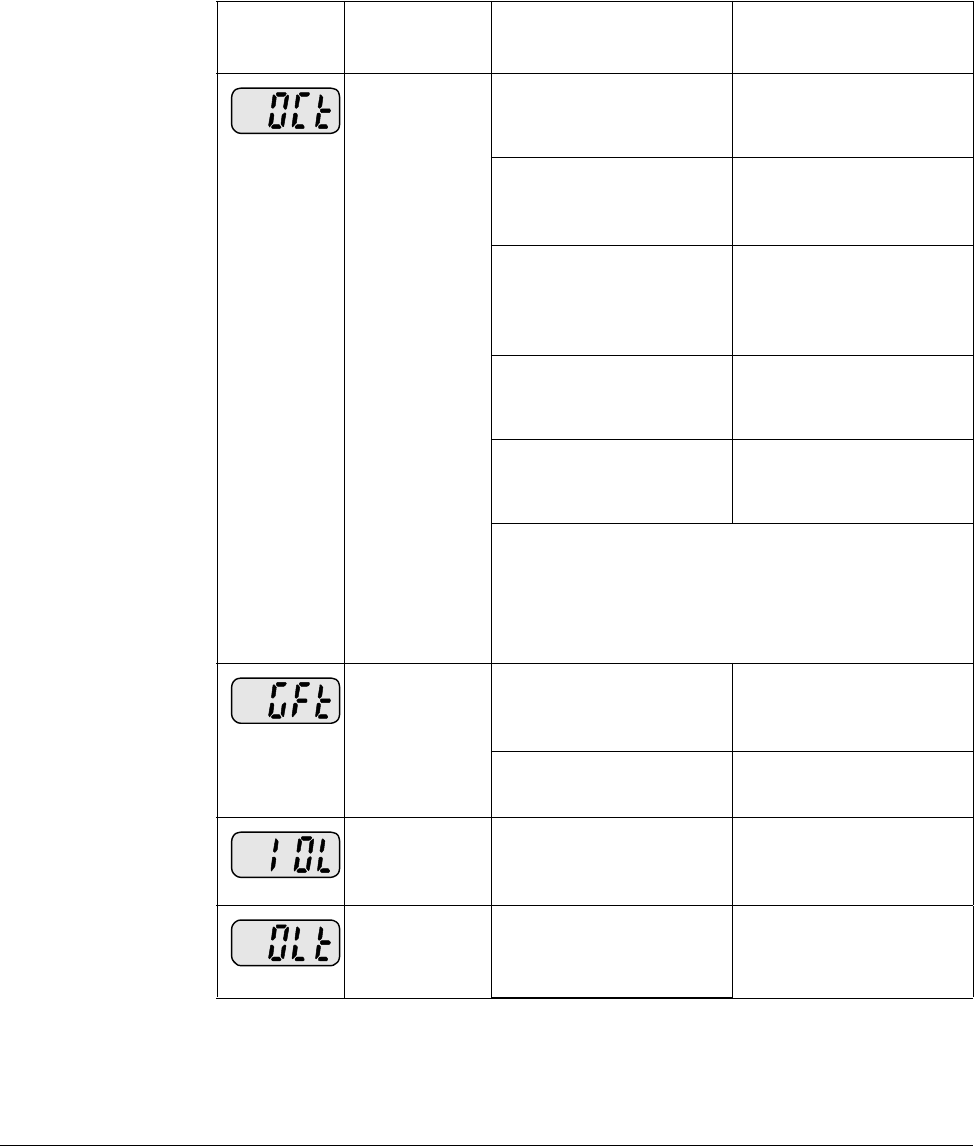
Troubleshooting 9-7
9.6 Fault Correction
Use table 9.2 to troubleshoot the drive. If you cannot resolve the problem using this
table, contact Baldor-Reliance.
Table 9.2 – Corrective Actions
Keypad
Display Fault Cause Remedy
Overcurrent •Accel/Decel time is
too short compared to
the inertia of the load.
•Increase the
Accel/Decel time.
•Load is greater than
the drive rating. •Replace the inverter
with appropriate
capacity
•Inverter enabled when
the motor is rotating. •Resume operation
after stopping the
motor or use H22
(Speed search).
•Output short circuit or
ground fault has
occurred.
•Check output wiring.
•Mechanical brake on
the motor is operating
incorrectly.
•Check the mechanical
brake
ATTENTION:When an overcurrent fault occurs,
the cause of the fault must be corrected before
operation is restarted. Failure to observe this
precaution could result in damage to, or
destruction of, the IGBT.
Ground fault
current •Ground fault has
occurred in the output
wiring of the drive.
•Check the wiring
between the drive and
the motor.
•The insulation of the
motor is damaged. •Replace the motor.
Inverter
Overload •Load is greater than
the drive rating. •Upgrade the capacity
of motor and drive or
reduce the load.
Overload trip •Torque boost scale is
set too large. •Reduce torque boost
scale.
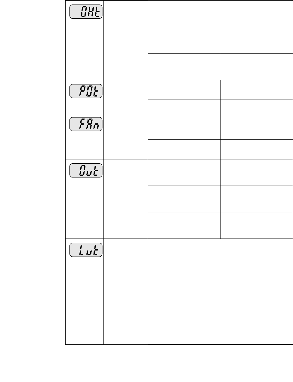
9-8 VS1-MD AC Drive User Manual
Inverter
overheat •Cooling system has
problems. •Check for foreign
substances clogged in
the heat sink.
•Cooling fan has failed. •Replace the old
cooling fan with a new
one.
•Ambient temperature
is too high. •Keep ambient
temperature under 50
degrees C.
Output Phase
loss •Faulty contact in
output contactor. •Replace or repair
output contactor.
•Faulty output wiring •Check output wiring.
Cooling Fan
Fault •An foreign substance
is clogged in a
ventilating slot.
•Check the ventilating
slot and remove the
clogged substances.
•Cooling fan has failed. •Replace the cooling
fan.
Over voltage •Decel time is too short
for the inertia of the
load.
•Increase the Decel
time.
•Regenerative load is
connected to the
drive.
•Use Dynamic Brake
Unit.
•Line voltage is too
high. •Check to see if line
voltage exceeds the
rating.
Low voltage •Line voltage is low. •Check to see if line
voltage is below the
rating.
•Load larger than line
capacity is connected
to line (ex: welding
machine, motor with
high starting current
connected to the
commercial line).
•Check the incoming
AC line. Adjust the
line capacity
corresponding to the
load.
•Faulty contactor on
the input of the
inverter.
•Change contactor.
Table 9.2 – Corrective Actions
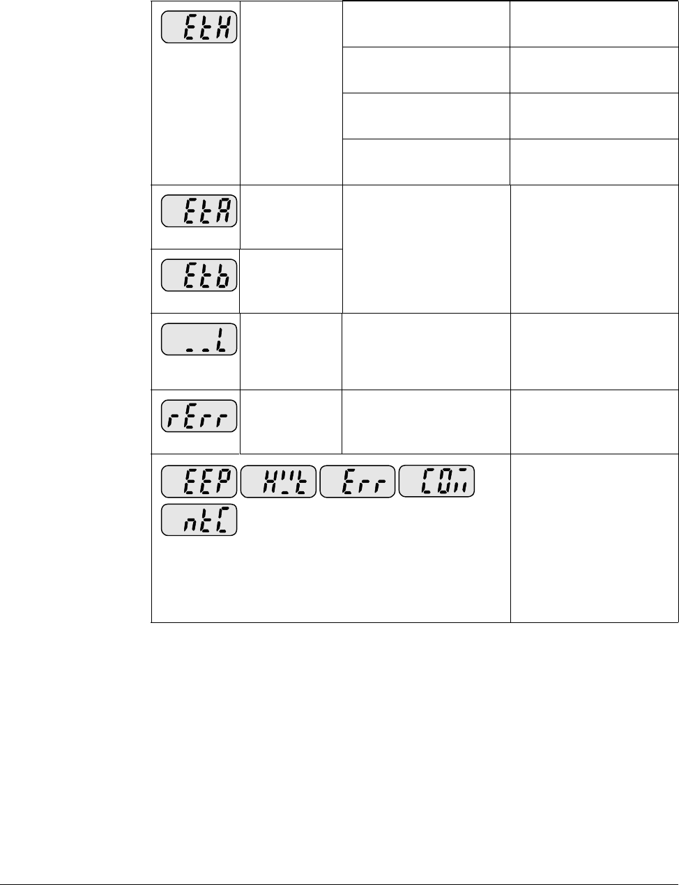
Troubleshooting 9-9
9.7 Overload Protection
IOLT : IOLT(inverter Overload Trip) protection is activated at 150% of the inverter
rated current for 1 minute and greater.
OLT : OLT is selected when F56 is set to 1 and activated at 200% of F57[Motor rated
current] for 60 sec in F58. This can be programmable.
Electronic
Thermal •Motor has
overheated. •Reduce load and/or
duty cycle.
•Load is greater than
inverter rating. •Change drive with
higher capacity.
•ETH level is set too
low. •Adjust ETH level to an
appropriate level.
•Drive capacity is
incorrectly selected. •Select correct drive
capacity.
External fault A
contact input •The terminal set to “18
(External fault-A)” or
“19 (External fault-B)”
in t1-t8 within terminal.
•Eliminate the cause of
fault in the circuit
connected to external
fault terminal.
External fault B
contact input
Operating
method when
the frequency
command is
lost
•No frequency
command is applied to
V1 and I.
•Check the wiring of V1
and I and frequency
reference level.
Remote
keypad
communication
error
•Communication error
between drive keypad
and remote keypad.
•Check for connection
of communication line
and connector.
EEP: Parameter save error
HWT: Hardware fault
Err: Communication error
COM: Keypad error
NTC: NTC error
•Call Baldor-Reliance
for assistance.
Table 9.2 – Corrective Actions

9-10 VS1-MD AC Drive User Manual

Technical Specifications A-1
APPENDIX A
Technical Specifications
Appendix A provides technical specifications for the VS1MD drive..
Environment
Altitude 1000 m, (3300 ft.), max without derating
Vibration 5.9m/sec2, (0.6G)
Ambient Operating
Temperature -10º to 50º C, (14 to 122º F)
Storage Temperature -20º to 65º C, (-4 to 149º F)
Relative Humidity 90%, non-condensing
Cooling Method Natural Convection / Forced Air Cooling,
(Fan)
Atmosphere Important: The drive must not be installed in
an area exposed to volatile or corrosive gas,
vapors or dust. If the drive will be stored for a
time before installation, it must be stored in an
area where it will not be exposed to a
corrosive atmosphere.
Control
Control Method V/Hz, Sensorless Vector
Speed Reference
Resolution Digital command: 0.01Hz
Analog signal command: 0.06 Hz, (Max freq.,
60 Hz)
Frequency Accuracy Digital command: 0.01% of Max output freq.
Analog signal command: 0.1% of Max output
freq.
V/Hz Curve Linear, Squared, User custom V/Hz.
Terminal Strip Input
P1 – P8 Multi-function programmable inputs, T/M 1-8
CM Common terminal

A-2 VS1MD User Manual
V1, Voltage Analog
Input -12 - +12 VDC max.
I, Analog Current
Input 0 – 20 mA, Internal resistor, 250 Ohm
Terminal Strip Outputs
VR, Reference
Power Supply 12 VDC Output, 10mA max. Potentiometer 1
– 5 Kohm
AM, Multi-function
Analog Output
Signal
11 VDC, 100 mA max.
MO, Multi-function
Terminal, Open
Collector
<26 VDC, 100 mA
MG, External Power Supply Ground Terminal
24, Power Supply 100 mA max output current
3A
3B
3C, common
Multi-function Relay Output Terminals: Max.
250 VAC, 1A
30 VDC, 1A
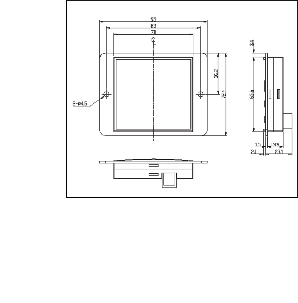
Options & Kits B-1
APPENDIX B
Options & Kits
B.1 Remote Option
B.1.1 Remote Keypad
(0.083)
(
0
(0.059)
(3.74)
(3.27)
(2.76)
(2.85)
(1.43)
(2.58) (0.134)
(0.083) (0.91)
(0.059) (0.55)
(0.177)
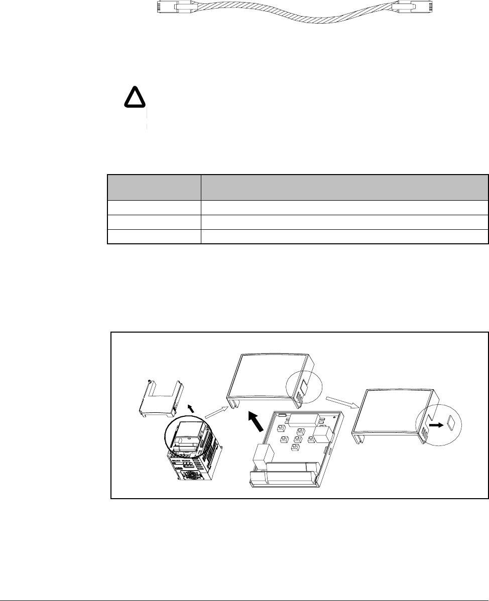
B-2 VS1MD User Manual
B.1.2 Remote Cable (2M,3M,5M)
B.1.3 Remote Keypad and Cable Model Numbers
B.1.4 Installation
Step 1. Remove incoming power from VS1MD and wait 10 minutes.
Step 2. Take off the top cover of the I/O board kit and remove the hole cover to
connect remote cable on the side.
!
!
CAUTION: Only Baldor cables dhould be used to connect the keypad
and control. These are special cables to protect the control and keypad.
Damage associated with other cable types are not coverd by the Baldor
warranty.
Model number Description
VS1MD-RKEY2 VS1MD to Remote Keypad 2 meter length (6.5 feet)
VS1MD-RKEY3 VS1MD to Remote Keypad 3 meter length (9.8 feet)
VS1MD-RKEY5 VS1MD to Remote Keypad 5 meter length (16.4 feet)
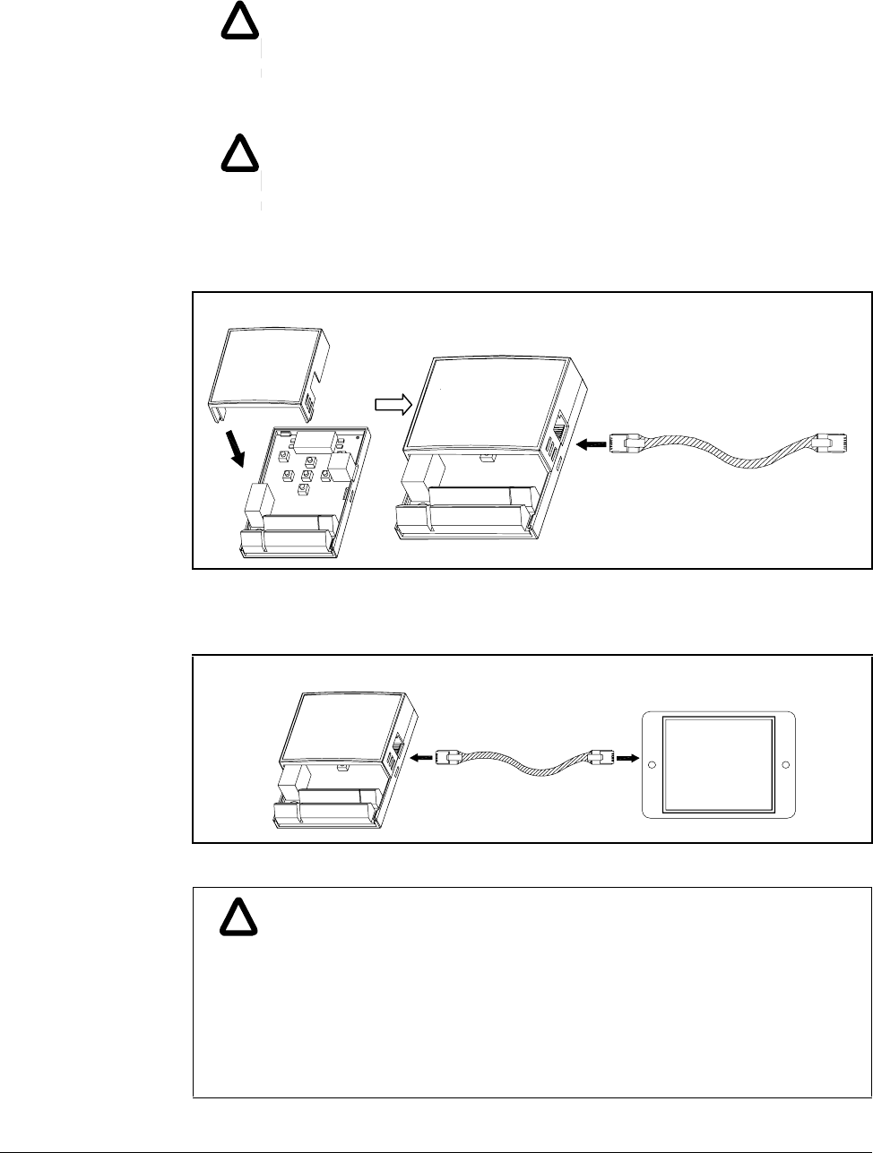
Options & Kits B-3
Step 3. Attach the top cover of the I/O board kit and connect the remote cable as
shown below.
Step 4. Connect the other side of the remote cable to the remote keypad as shown
below.
!
!
WARNING: Do not touch any circuit board, power device or electrical
connection before you first ensure that power has been disconnected and
there is no high voltage present from this equipment or other equipment to
which it is connected. Electrical shock can cause serious or fatal injury.
Only qualified personnel should attempt the start-up procedure or
troubleshoot this equipment.
!
!
WARNING: Do not remove cover for at least ten (10) minutes after AC
power is disconnected to allow capacitors to discharge. Dangerous
voltages are present inside the equipment. Electrical shock can cause
serious or fatal injury.
!
!
ATTENTION:Without Parameter Read (H91), Parameter Write (H92) is
not available since the Remote memory is empty when the Remote
keypad is first used.
ATTENTION:Use only the remote cable supplied in the kit. Other cables
may introduce noise and/or voltage drop and cause erratic or improper
drive operation.
ATTENTION:Check for disconnection of the communication cable
and/or poor cable connection if ì----ì is displayed on the 7-segment
display of the Remote keypad.
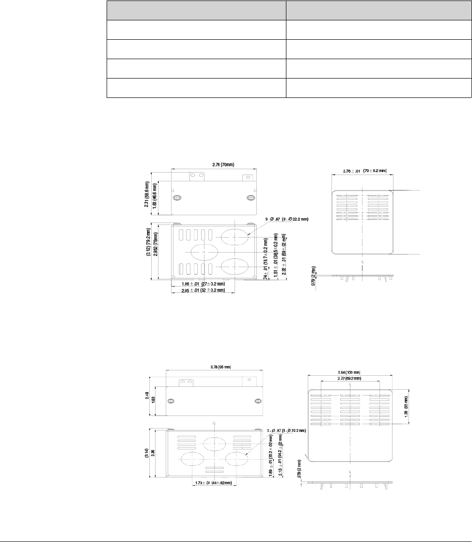
B-4 VS1MD User Manual
B.2 Conduit Kit
B.2.1 Conduit Kit Model Numbers
B.2.2 VS1MD-NM1A
B.2.3 VS2MD-NM1B
Conduit Kit Model
VS1MD-NM1A 0.5 and 1.0 HP (0.4 and 0.75 kW)
VS1MD-NM1B 2.0 HP (1.5 kW)
VS1MD-NM1C 3.0 and 5.0 HP (2.2 and 4.0 kW)
VS1MD-NM1D 7.5 and 10.0 HP (5.5 and 7.5 kW)
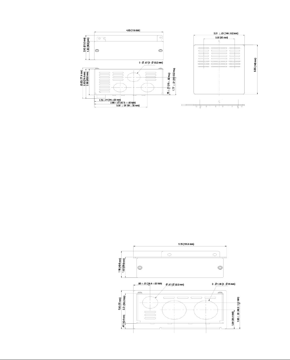
Options & Kits B-5
B.2.4 VS1MD-NM1C
B.2.5 VS1MD-NM1D
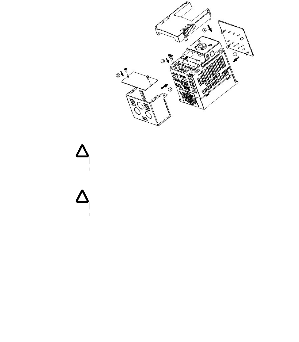
B-6 VS1MD User Manual
B.2.6 Installation
B.2.6.1 VS1MD-NM1A, VS1MD-NM1B, VS1MD-NM1C
Preparation:
Step 1. Remove input power from drive and wait 10 minutes before proceeding.
Step 2. Remove cover from drive exposing the terminal strips.
Step 3. Remove two screws from ground connection bar inside drive to the left of
the power terminals. Retain screws.
Step 4. Remove two screws and cover from front of conduit kit. Retain screws.
Installation (refer to legends in diagram):
Step 1. Snap top vent cover onto the top of the drive, ensuring that all four tabs
correctly engage their respective openings in the drive vent holes.
Step 2. Place the conduit kit, less the cover, such that the lower left tab with the
two holes is over the ground connection bar holes and the top right tab is
inserted in the provided slot, near the bottom right of the drive.
!
!
WARNING: Do not touch any circuit board, power device or electrical
connection before you first ensure that power has been disconnected and
there is no high voltage present from this equipment or other equipment to
which it is connected. Electrical shock can cause serious or fatal injury.
Only qualified personnel should attempt the start-up procedure or
troubleshoot this equipment.
!
!
WARNING: Do not remove cover for at least ten (10) minutes after AC
power is disconnected to allow capacitors to discharge. Dangerous
voltages are present inside the equipment. Electrical shock can cause
serious or fatal injury.
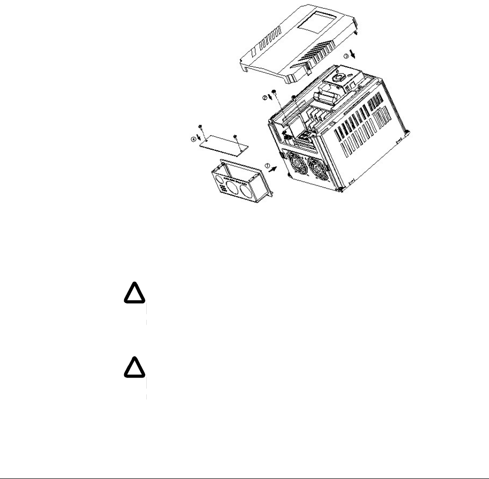
Options & Kits B-7
Step 3. Install the two screws removed from the ground connection bar during
preparation Step 3 such that they are inserted through the two holes in the
conduit kit prior to engaging the ground connection bar. Install the screw
provded with the conduit kit through the hole in the bottom right corner of the
drive into the top right tab of the conduit kit.
Step 4. After connecting conduits and making control and power connections,
replace the drive cover.
Step 5. Replace the conduit kit cover utilizing the two screws removed in preparation
Step 4.
B.2.6.2 VS1MD-NM1D
Preparation:
Step 1. Remove input power from drive and wait 10 minutes before proceeding.
Step 2. Remove cover from drive, exposing terminal strips.
Step 3. Remove two screws holding wire gland plate to drive. Retain screws.
Remove and discard wire gland plate.
!
!
WARNING: Do not touch any circuit board, power device or electrical
connection before you first ensure that power has been disconnected and
there is no high voltage present from this equipment or other equipment to
which it is connected. Electrical shock can cause serious or fatal injury.
Only qualified personnel should attempt the start-up procedure or
troubleshoot this equipment.
!
!
WARNING: Do not remove cover for at least ten (10) minutes after AC
power is disconnected to allow capacitors to discharge. Dangerous
voltages are present inside the equipment. Electrical shock can cause
serious or fatal injury.

B-8 VS1MD User Manual
Step 4. Remove two screws and cover from front of conduit kit. Retain screws.
Installation:
Step 1. Slide conduit kit into slots in bottom of drive from which wire gland plate was
removed.
Step 2. Install the two screws removed from the wire gland plate during preparation
Step 3 such that they are inserted through the two holes in the conduit kit
prior to engaging the tapped holes in the drive.
Step 3. After connecting conduits and making control and power connections,
replace the drive cover.
Step 4. Replace the conduit kit cover utilizing the two screws removed in preparation
Step 4.
B.2.7 Conduit Hole Size
NOTE: Choose the proper size of the UL recognized Locknut and Bushing
corresponding to size of the Conduit in use.
Conduit Kit
Conduit hole for control wiring
inches (mm) Size of the Conduit
Inches (Metric)
Conduit hole for power wiring
inches (mm)
VS1MD-NM1A 0.87 (22.2) 1/2 (16)
0.87 (22.2) 1/2 (16)
VS1MD-NM1B 0.87 (22.2) 1/2 (16)
0.87 (22.2) 1/2 (16)
VS1MD-NM1C 0.87 (22.2) 1/2 (16)
0.87 (22.2) 1/2 (16)
VS1MD-NM1D 0.87 (22.2) 1/2 (16)
1.38 (35.0) 1 (27)

Options & Kits B-9
B.3 Braking Resistor
Input
Voltage
Inverter
capacity HP
(kW)
100 % braking 150% braking
ΩΩ1
1The wattage is based upon a 5% duty cycle with maximum continuous
braking time of 15 sec.
ΩΩ1
230
0.5 (0.4) 400 50 300 100
1.0 (0.75) 200 100 150 150
2.0 (1.5) 100 200 60 300
3.0 (2.2) 60 300 50 400
5.0 (3.7) 40 500 33 600
7.5 (5.5) 30 700 20 800
10.0 (7.5) 20 1000 15 1200
460
0.5 (0.4) 1800 50 1200 100
1.0 (0.75) 900 100 600 150
2.0 (1.5) 450 200 300 300
3.0 (2.2) 300 300 200 400
5.0 (3.7) 200 500 130 600
7.5 (5.5) 120 700 85 1000
10.0 (7.5) 90 1000 60 1200

B-10 VS1MD User Manual

RS485 Protocol C-1
APPENDIX C
RS485 Protocol
C.1 Introduction
The drive can be controlled and monitored by the program of aPLC or other master
module.
Drives or other slave devices may be connected in a multi-drop fashion on the RS-485
network and may be monitored or controlled by a single PLC or PC. Parameters can
be set and changed through the PLC or PC.
C.1.1 Features
The VS1MD can easily be utilized for factory automation applications because
operation and monitoring are available by the user’s program.
•Parameter change and monitoring is available via computer. (Ex: Accel/Decel time,
Freq. Command etc.)
•RS484 Interface:
1. Allows the drive to communicate with any other computers or PLC’s.
2. Allows connection of up to 31 drives with multi-drop link network.
3. Inherent noise immune design.
Users can use readily available RS232-485 converters. The specifications of
converters depend on the manufacturers.
C.1.2 Before Installation
!
ATTENTION:Before installation and operation, this manual should be
read thoroughly. Failure to observe this precaution could result in
personal injury or damage to the equipment.

C-2 VS1MD User Manual
C.2 Specifications
C.2.1 Performance Specifications
C.2.2 Hardware Specifications
C.2.3 Communication Specifications
Item Specification
Communication method RS485
Transmission form Bus method, Multi drop Link System
Applicable inverter VS1MD series
Converter RS232 converter
Connectable drives Max 31
Transmission distance Max. 1,200m (Within 700m Recommend)
Item Specification
Installation Use S+, S- terminals on control terminal block
Power supply Use Insulated power from the inverter power supply
Item Specification
Communication speed 19,200/9,600/4,800/2,400/1,200 bps selectable
Control procedure Asynchronous communication system
Communication system Half duplex system
Character system ASCII (8 bit)
Stop bit length Modbus-RTU: 2 bit LS Bus: 1 bit
Sum check 2 byte
Parity check None

RS485 Protocol C-3
C.3 Installation
C.3.1 Connecting the Communication Line
Step 1. Connect the RS485 communication line to the inverter’s (S+), (S-) terminals
of the control terminals.
Step 2. Check the connection and turn ON the inverter.
Step 3. If the communication line is connected correctly, set the
communication-related parameters as follows:
•P38 [Drive mode]: 3(RS485)
•P40 [Freq. mode]: 7(RS485)
•t60 [Inv. Number]: 1 to 250 (If multiple inverters are connected, be sure to use
different numbers for each inverter)
•t61 [Baud-rate]: 3 (9,600 bps as Factory default)
•t62 [Lost Mode]: 0 - No action (Factory default)
•t63 [Time-Out]: 1.0 sec (Factory default)
•t59 [Comm. Prot]: 0 - Modbus-RTU
C.3.2 Computer and Inverter Connection
The maximum number of drives that can be connected is 31.
The maximum length of communication line is 1200m. To ensure stable
communication, keep the length to less than 700m.
C.4 Operation
C.4.1 Operating steps
Step 1. Check whether the computer and the inverter are connected correctly.
Step 2. Turn ON the inverter. But do not connect the load until stable communication
between the computer and the inverter is verified.
Step 3. Start the operating program for the inverter from the computer.
Step 4. Operate the inverter using the operating program for the inverter.
Step 5. Refer to Chapter 9: Troubleshooting if the communication is not operating.
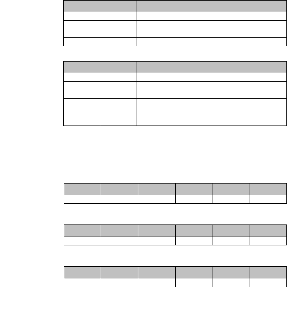
C-4 VS1MD User Manual
C.5 Communication Protocol (MODBUS-RTU)
Use Modbus-RTU protocol (Open protocol).
Computer or other hosts can be Master and inverters Slave. Inverter responds to
Read/Write command from Master.
C.6 Communication Protocol (LS Bus)
C.6.1 Basic Format
Command message (Request):
Normal response (Acknowledge Response):
Negative response (Negative Acknowledge Response):
Table C.1 – Supported function codes
Function code Description
0x03 Read Hold Register
0x04 Read Input Register
0x06 Preset Single Register
0x10 Preset Multiple Register
Table C.2 – Exception codes
Function code Description
0x01 ILLEGAL FUNCTION
0x02 ILLEGAL DATA ADDRESS
0x03 ILLEGAL DATA VALUE
0x06 SLAVE DEVICE BUSY
User
define 0x14 1.Write Disable (Address 0x0004 value is 0).
2.Read Only or Not Program during Running.
ENQ Drive No. CMD Data SUM EOT
1 byte 2 bytes 1 byte n bytes 2 bytes 1 byte
ACK Drive No. CMD Data SUM EOT
1 byte 2 bytes 1 byte n * 4 bytes 2 bytes 1 byte
NAK Drive No. CMD Error code SUM EOT
1 byte 2 bytes 1 byte 2 bytes 2 bytes 1 byte

RS485 Protocol C-5
Description:
Request starts with “ENQ” and ends with “EOT”.
Acknowledge Response starts with “ACK” and ends with “EOT”.
Negative Acknowledge Response starts with ”NAK” and ends with “EOT”.
“Drive Number” is the number of the drive and is indicated in 2 byte ASCII-HEX.
(ASCII-HEX: Hexadecimal consists of ‘0’ to ‘9’, ‘A’ to ‘F)
CMD: Capital letter
Data: ASCII-HEX
Example: when data value is 3000: 3000 (dec) ‘0’ ‘B’ ‘B’ ‘8’h 30h 42h 42h 38h
Error code: ASCII (20h to 7Fh)
Receive/Send buffer size: Receive= 39 byte, Send=44 byte
Monitor register buffer: 8 Word
SUM: to check the communication error
SUM= ASCII-HEX format of lower 8 bit of (Drive No. + CMD + DATA)
Example: Command Message (Request) to read one address from address “3000”
SUM = ‘0’ + ‘1’ + ’R’ + ‘3’ + ‘0’ + ‘0’ + ‘0’ + ‘1’
=30h + 31h + 52h + 33h + 30h + 30h + 30h + 31h
= 1A7h (Control values such as ENQ/ACK/NAK are excluded.)
Character ASCII-HEX Command
R 52h Read
W 57h Write
X 58h Request for monitoring
Y 59h Action for monitoring
ENQ Drive
No CMD Address Number of address to
read SUM EOT
05h “01” “R” “3000” “1” “A7” 04h
1 byte 2 bytes 1 byte 4 bytes 1 byte 2 1
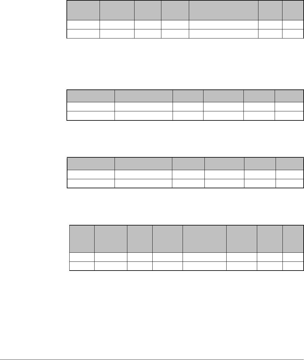
C-6 VS1MD User Manual
C.6.2 Detail Communication Protocol
C.6.2.1 Request for Read:
Request to read successive ‘N’ numbers of WORD from address “XXXX”.
Total bytes = 12
Note: Quotation marks (“ ”) indicate character.
C.6.2.2 Acknowledge Response:
Total bytes= 7 + n * 4 = Max 39
C.6.2.3 Negative Acknowledge Response:
Total bytes = 9
C.6.2.4 Request for Write:
Total bytes = 12 + n * 4 = Max 44
ENQ Drive No CMD Addres
sNumber of address to
read SUM EOT
05h “01” to “R” “XXXX “1” to “8” = n “XX” 04h
1 byte 2 bytes 1 byte 4 bytes 1 byte 2 1
ACK Drive No CMD Data SUM EOT
06h “01” to “1F” “R” “XXXX” “XX” 04h
1 byte 2 bytes 1 byte N * 4 bytes 2 byte 1 byte
NAK Drive No CMD Error code SUM EOT
15h “01” to “1F” “R” “**” “XX” 04h
1 byte 2 bytes 1 byte 2 bytes 2 bytes 1 byte
ENQ Drive No CMD Address Number of
address to
read
Data SUM EOT
05h “01” to “W” “XXXX” “1” to “8” = n “XXXX “XX” 04h
1 byte 2 bytes 1 byte 4 bytes 1 byte n*4 2 1
RS485 Protocol C-7
C.6.2.5 Acknowledge Response:
Total bytes = 7 + n * 4 = Max 39
Note: When Request for Write and Acknowledge Response is exchanged between
PC and Inverter for the first time, previous data is returned. From subsequent
transmissions, the current data will be returned.
C.6.2.6 Negative Response:
Total bytes = 9
C.6.2.7 Request for Monitor Register
This is useful when constant parameter monitoring and data updates are required.
Request for Register of ‘n’ numbers of Address (not consecutive)
Total bytes = 8 + n * 4 = Max 40
C.6.2.8 Acknowledge Response:
Total bytes = 7
C.6.2.9 Negative Acknowledge Response:
Total bytes = 9
ACK Drive No CMD Data SUM EOT
06h “01” to “1F” “W” “XXXX…” “XX” 04h
1:byte 2:bytes 1:byte n * 4 bytes 2 bytes 1
NAK Drive No CMD Error code SUM EOT
15h “01” to “1F” “W” “**” “XX” 04h
1 byte 2 bytes 1 byte 2 bytes 2 bytes 1
ENQ Drive No CMD Number of address to
read Addres
sSUM EOT
05h “01” to “X” “1” to “8”=n “XXXX “XX” 04h
1 byte 2 bytes 1 1 byte n * 4 2 byte 1
ACK Drive No CMD SUM EOT
06h “01” to “1F” “X” “XX” 04h
1 byte 2 bytes 1 byte 2 bytes 1 byte
NAK Drive No CMD Error code SUM EOT
15h “01” to “1F” “X” “**” “XX” 04h
1 byte 2 bytes 1 byte 2 bytes 2 bytes 1 byte

C-8 VS1MD User Manual
C.6.2.10 Action Request for Monitor Register:
Request to read address registered by monitor register.
Total bytes = 7
C.6.2.11Acknowledge Response:
Total bytes = 7 + n * 4 = Max 39
C.6.2.12Negative Response:
Total bytes = 9
C.6.2.13Error codes
ENQ Drive No CMD SUM EOT
05h “01” to “1F” “Y” “XX” 04h
1 byte 2 bytes 1 byte 2 bytes 1 byte
ACK Drive No CMD Data SUM EOT
06h “01” to “1F” “Y” “XXXX…” “XX” 04h
1 byte 2 bytes 1 byte n * 4 bytes 2 bytes 1 byte
NAK Drive No CMD Error code SUM EOT
15h “01” to “1F” “Y” “**” “XX” 04h
1 byte 2 bytes 1 byte 2 bytes 2 bytes 1 byte
Error code Description
“IF” When master is sending codes other than Function code (R, W, X,
“IA” When parameter address does not exist
“ID” When Data value exceeds its permissible range during ‘W’ (Write).
“WM” When the specific parameters cannot be written during ‘W’ (Write).
(For example, in the case of Read Only, Write disabled during Run)
“FE” When frame size of specific function is not correct and Checksum

RS485 Protocol C-9
C.7 Troubleshooting
Refer to Troubleshooting when RS 485 communication error occurs.
Check Points Corrective Measures
Is power provided to the converter? Provide electric power to the converter.
Are the connections between converter
and computer correct? Refer to the converter manual.
Is Master not polling? Verify the Master is polling the drive.
Is baud rate of computer and drive set
correctly? Set the correct value.
Is the data format of user program
correct? Set data formats equal between drive and
computer.
Is the connection between the converter
and the communication card correct? Check for the correct wiring.

C-10 VS1MD User Manual
C.8 Miscellaneous
ASCII Code List
Character Hex Character Hex Character Hex Character Hex Character Hex
A
B
C
D
E
F
G
H
I
J
K
L
M
N
O
P
Q
R
S
T
U
V
W
X
Y
Z
41
42
43
44
45
46
47
48
49
4A
4B
4C
4D
4E
4F
50
51
52
53
54
55
56
57
58
59
5A
a
b
c
d
e
f
g
h
i
J
k
l
m
n
o
p
q
r
s
t
u
v
w
x
y
z
61
62
63
64
65
66
67
68
69
6A
6B
6C
6D
6E
6F
70
71
72
73
74
75
76
77
78
79
7A
0
1
2
3
4
5
6
7
8
9
space
!
"
#
$
%
&
'
(
)
*
+
,
-
.
/
30
31
32
33
34
35
36
37
38
39
20
21
22
23
24
25
26
27
28
29
2A
2B
2C
2D
2E
2F
:
;
<
=
>
?
@
[
\
]
{
|
}
to
BEL
BS
CAN
CR
DC1
DC2
DC3
DC4
DEL
3A
3B
3C
3D
3E
3F
40
5B
5C
5D
5E
5F
60
7B
7C
7D
7E
07
08
18
0D
11
12
13
14
7F
DLE
EM
ACK
ENQ
EOT
ESC
ETB
ETX
FF
FS
GS
HT
LF
NAK
NUL
RS
S1
SO
SOH
STX
SUB
SYN
US
VT
10
19
06
05
04
1B
17
03
0C
1C
1D
09
0A
15
00
1E
0F
0E
01
02
1A
16
1F
0B

DIF
Documentation
Improvement Form
Use this form to give us your comments concerning this publication or to report an
error that you have found. For convenience, you may attach copies of the pages with
your comments. After you have completed this form, please return it to:
Baldor V*S Drives
Technical Documentation
6040 Ponders Court
Greenville, SC 29615
Fax: 864-284-5483
Thank you for your comments.
Publication Name: VS1MD User Manual
Publication Date: 2007
Comments:
Your Name: Date:
Company Name: Phone: ( )
Address:
Technical Writing Internal Use
Date: DIF Number:
Follow-Up Action:

VS1MD User Manual
Publication MN760-3 2007 Baldor Electric Company. All rights reserved
.
