Baldor Mn1854 LinStep+ 2 Axis User Manual To The Cf133e94 D741 4ff3 9897 8b39c295baae
User Manual: Baldor mn1854 to the manual
Open the PDF directly: View PDF ![]() .
.
Page Count: 105 [warning: Documents this large are best viewed by clicking the View PDF Link!]

LinStep+ Dual–Axis
Microstepping Indexer/Driver
Installation & Operating Manual
7/01 MN1854

Table of Contents
Table of Contents iMN1854
Section 1
General Information 1-1. . . . . . . . . . . . . . . . . . . . . . . . . . . . . . . . . . . . . . . . . . . . . . . . . . . . . . . . . . . . . .
CE Compliance 1-1. . . . . . . . . . . . . . . . . . . . . . . . . . . . . . . . . . . . . . . . . . . . . . . . . . . . . . . . . . . . . . .
Limited Warranty 1-1. . . . . . . . . . . . . . . . . . . . . . . . . . . . . . . . . . . . . . . . . . . . . . . . . . . . . . . . . . . . . .
Product Notice 1-2. . . . . . . . . . . . . . . . . . . . . . . . . . . . . . . . . . . . . . . . . . . . . . . . . . . . . . . . . . . . . . . .
Safety Notice 1-2. . . . . . . . . . . . . . . . . . . . . . . . . . . . . . . . . . . . . . . . . . . . . . . . . . . . . . . . . . . . . . . . .
Section 2
Product Overview 2-1. . . . . . . . . . . . . . . . . . . . . . . . . . . . . . . . . . . . . . . . . . . . . . . . . . . . . . . . . . . . . . . .
Section 3
Receiving and Installation 3-1. . . . . . . . . . . . . . . . . . . . . . . . . . . . . . . . . . . . . . . . . . . . . . . . . . . . . . . .
Receiving & Inspection 3-1. . . . . . . . . . . . . . . . . . . . . . . . . . . . . . . . . . . . . . . . . . . . . . . . . . . . . . . .
Location Considerations 3-1. . . . . . . . . . . . . . . . . . . . . . . . . . . . . . . . . . . . . . . . . . . . . . . . . . . . . . .
Power Dissipation 3-1. . . . . . . . . . . . . . . . . . . . . . . . . . . . . . . . . . . . . . . . . . . . . . . . . . . . . . . . . . . . .
Mechanical Installation 3-1. . . . . . . . . . . . . . . . . . . . . . . . . . . . . . . . . . . . . . . . . . . . . . . . . . . . . . . .
Electrical Installation 3-2. . . . . . . . . . . . . . . . . . . . . . . . . . . . . . . . . . . . . . . . . . . . . . . . . . . . . . . . . .
System Grounding 3-2. . . . . . . . . . . . . . . . . . . . . . . . . . . . . . . . . . . . . . . . . . . . . . . . . . . . . . . .
Power Disconnect 3-3. . . . . . . . . . . . . . . . . . . . . . . . . . . . . . . . . . . . . . . . . . . . . . . . . . . . . . . .
Protection Devices 3-3. . . . . . . . . . . . . . . . . . . . . . . . . . . . . . . . . . . . . . . . . . . . . . . . . . . . . . . .
Power Connections 3-4. . . . . . . . . . . . . . . . . . . . . . . . . . . . . . . . . . . . . . . . . . . . . . . . . . . . . . .
RS232/Keypad Installation 3-6. . . . . . . . . . . . . . . . . . . . . . . . . . . . . . . . . . . . . . . . . . . . . . . . .
RS–232 PC Connections 3-7. . . . . . . . . . . . . . . . . . . . . . . . . . . . . . . . . . . . . . . . . . . . . . . . . .
Programmable I/O Connections 3-9. . . . . . . . . . . . . . . . . . . . . . . . . . . . . . . . . . . . . . . . . . . . . . . . .
Optional Opto I/O Connections 3-9. . . . . . . . . . . . . . . . . . . . . . . . . . . . . . . . . . . . . . . . . . . . . . . . .
Encoder Connections 3-10. . . . . . . . . . . . . . . . . . . . . . . . . . . . . . . . . . . . . . . . . . . . . . . . . . . . . . . . . .
Motor Connections 3-11. . . . . . . . . . . . . . . . . . . . . . . . . . . . . . . . . . . . . . . . . . . . . . . . . . . . . . . . . . . .
Start-Up Procedure 3-12. . . . . . . . . . . . . . . . . . . . . . . . . . . . . . . . . . . . . . . . . . . . . . . . . . . . . . . . . . .
Power Off Checks 3-12. . . . . . . . . . . . . . . . . . . . . . . . . . . . . . . . . . . . . . . . . . . . . . . . . . . . . . . .
Switch and Potentiometer Settings 3-12. . . . . . . . . . . . . . . . . . . . . . . . . . . . . . . . . . . . . . . . . .
Power On Checks 3-13. . . . . . . . . . . . . . . . . . . . . . . . . . . . . . . . . . . . . . . . . . . . . . . . . . . . . . . .

ii Table of Contents MN1854
Section 4
Keypad Operation 4-1. . . . . . . . . . . . . . . . . . . . . . . . . . . . . . . . . . . . . . . . . . . . . . . . . . . . . . . . . . . . . . . .
Overview 4-1. . . . . . . . . . . . . . . . . . . . . . . . . . . . . . . . . . . . . . . . . . . . . . . . . . . . . . . . . . . . . . . . . . . .
Run Menu 4-3. . . . . . . . . . . . . . . . . . . . . . . . . . . . . . . . . . . . . . . . . . . . . . . . . . . . . . . . . . . . . . . . . . .
PROG 4-3. . . . . . . . . . . . . . . . . . . . . . . . . . . . . . . . . . . . . . . . . . . . . . . . . . . . . . . . . . . . . . . . . .
JOG 4-3. . . . . . . . . . . . . . . . . . . . . . . . . . . . . . . . . . . . . . . . . . . . . . . . . . . . . . . . . . . . . . . . . . . .
Test 4-4. . . . . . . . . . . . . . . . . . . . . . . . . . . . . . . . . . . . . . . . . . . . . . . . . . . . . . . . . . . . . . . . . . . . .
Edit Menu 4-5. . . . . . . . . . . . . . . . . . . . . . . . . . . . . . . . . . . . . . . . . . . . . . . . . . . . . . . . . . . . . . . . . . . .
PROG 4-5. . . . . . . . . . . . . . . . . . . . . . . . . . . . . . . . . . . . . . . . . . . . . . . . . . . . . . . . . . . . . . . . . .
Setup 4-9. . . . . . . . . . . . . . . . . . . . . . . . . . . . . . . . . . . . . . . . . . . . . . . . . . . . . . . . . . . . . . . . . . .
POS 4-10. . . . . . . . . . . . . . . . . . . . . . . . . . . . . . . . . . . . . . . . . . . . . . . . . . . . . . . . . . . . . . . . . . . .
List 4-10. . . . . . . . . . . . . . . . . . . . . . . . . . . . . . . . . . . . . . . . . . . . . . . . . . . . . . . . . . . . . . . . . . . . .
HELP Menu 4-11. . . . . . . . . . . . . . . . . . . . . . . . . . . . . . . . . . . . . . . . . . . . . . . . . . . . . . . . . . . . . . . . . .
COPY Menu 4-11. . . . . . . . . . . . . . . . . . . . . . . . . . . . . . . . . . . . . . . . . . . . . . . . . . . . . . . . . . . . . . . . .
PROG 4-11. . . . . . . . . . . . . . . . . . . . . . . . . . . . . . . . . . . . . . . . . . . . . . . . . . . . . . . . . . . . . . . . . .
TO PAD 4-11. . . . . . . . . . . . . . . . . . . . . . . . . . . . . . . . . . . . . . . . . . . . . . . . . . . . . . . . . . . . . . . . .
FROM 4-12. . . . . . . . . . . . . . . . . . . . . . . . . . . . . . . . . . . . . . . . . . . . . . . . . . . . . . . . . . . . . . . . . .
DEL Menu 4-12. . . . . . . . . . . . . . . . . . . . . . . . . . . . . . . . . . . . . . . . . . . . . . . . . . . . . . . . . . . . . . . . . . .
Section 5
Setup 5-1. . . . . . . . . . . . . . . . . . . . . . . . . . . . . . . . . . . . . . . . . . . . . . . . . . . . . . . . . . . . . . . . . . . . . . . . . . .
Overview 5-1. . . . . . . . . . . . . . . . . . . . . . . . . . . . . . . . . . . . . . . . . . . . . . . . . . . . . . . . . . . . . . . . . . . .
Configure Motor 5-2. . . . . . . . . . . . . . . . . . . . . . . . . . . . . . . . . . . . . . . . . . . . . . . . . . . . . . . . . . . . . .
Configure Encoder 5-3. . . . . . . . . . . . . . . . . . . . . . . . . . . . . . . . . . . . . . . . . . . . . . . . . . . . . . . . . . . .
Configure Your Application 5-5. . . . . . . . . . . . . . . . . . . . . . . . . . . . . . . . . . . . . . . . . . . . . . . . . . . . .
Configure the I/O 5-7. . . . . . . . . . . . . . . . . . . . . . . . . . . . . . . . . . . . . . . . . . . . . . . . . . . . . . . . . . . . .
Optional Opto I/O 5-11. . . . . . . . . . . . . . . . . . . . . . . . . . . . . . . . . . . . . . . . . . . . . . . . . . . . . . . . . . . . .
Configure the Output States 5-11. . . . . . . . . . . . . . . . . . . . . . . . . . . . . . . . . . . . . . . . . . . . . . . . . . . .
Configure End of Travel Switch Polarity 5-12. . . . . . . . . . . . . . . . . . . . . . . . . . . . . . . . . . . . . . . . . .
Configure JOG Parameters 5-12. . . . . . . . . . . . . . . . . . . . . . . . . . . . . . . . . . . . . . . . . . . . . . . . . . . .
Configure HOME Parameters 5-13. . . . . . . . . . . . . . . . . . . . . . . . . . . . . . . . . . . . . . . . . . . . . . . . . . .
Configure Power–up Program 5-15. . . . . . . . . . . . . . . . . . . . . . . . . . . . . . . . . . . . . . . . . . . . . . . . . .
Configure Serial Communications 5-16. . . . . . . . . . . . . . . . . . . . . . . . . . . . . . . . . . . . . . . . . . . . . . .
Configure Miscellaneous Setup Parameters 5-17. . . . . . . . . . . . . . . . . . . . . . . . . . . . . . . . . . . . . .
Section 6
Keypad Programming 6-1. . . . . . . . . . . . . . . . . . . . . . . . . . . . . . . . . . . . . . . . . . . . . . . . . . . . . . . . . . . .
Commands 6-1. . . . . . . . . . . . . . . . . . . . . . . . . . . . . . . . . . . . . . . . . . . . . . . . . . . . . . . . . . . . . . . . . .
Helpful Hints 6-24. . . . . . . . . . . . . . . . . . . . . . . . . . . . . . . . . . . . . . . . . . . . . . . . . . . . . . . . . . . . . . . . .
Variables 6-25. . . . . . . . . . . . . . . . . . . . . . . . . . . . . . . . . . . . . . . . . . . . . . . . . . . . . . . . . . . . . . . .
Arithmetic Operands and Equations 6-29. . . . . . . . . . . . . . . . . . . . . . . . . . . . . . . . . . . . . . . . .
Boolean Operators 6-29. . . . . . . . . . . . . . . . . . . . . . . . . . . . . . . . . . . . . . . . . . . . . . . . . . . . . . . .
Logical Operators 6-30. . . . . . . . . . . . . . . . . . . . . . . . . . . . . . . . . . . . . . . . . . . . . . . . . . . . . . . . .
Increment/Decrement Variables 6-30. . . . . . . . . . . . . . . . . . . . . . . . . . . . . . . . . . . . . . . . . . . .
Expressions 6-30. . . . . . . . . . . . . . . . . . . . . . . . . . . . . . . . . . . . . . . . . . . . . . . . . . . . . . . . . . . . .
Other Programming Samples 6-30. . . . . . . . . . . . . . . . . . . . . . . . . . . . . . . . . . . . . . . . . . . . . .

Table of Contents iiiMN1854
Section 7
Troubleshooting 7-1. . . . . . . . . . . . . . . . . . . . . . . . . . . . . . . . . . . . . . . . . . . . . . . . . . . . . . . . . . . . . . . . .
Serial Communications Problems 7-3. . . . . . . . . . . . . . . . . . . . . . . . . . . . . . . . . . . . . . . . . . . . . . .
Section 8
Specifications & Product Data 8-1. . . . . . . . . . . . . . . . . . . . . . . . . . . . . . . . . . . . . . . . . . . . . . . . . . . .
Identification 8-1. . . . . . . . . . . . . . . . . . . . . . . . . . . . . . . . . . . . . . . . . . . . . . . . . . . . . . . . . . . . . . . . .
General Specifications 8-2. . . . . . . . . . . . . . . . . . . . . . . . . . . . . . . . . . . . . . . . . . . . . . . . . . . . . . . . .
Dimensions 8-3. . . . . . . . . . . . . . . . . . . . . . . . . . . . . . . . . . . . . . . . . . . . . . . . . . . . . . . . . . . . . . . . . .
Section 9
CE Guidelines 9-1. . . . . . . . . . . . . . . . . . . . . . . . . . . . . . . . . . . . . . . . . . . . . . . . . . . . . . . . . . . . . . . . . . .
CE Declaration of Conformity 9-1. . . . . . . . . . . . . . . . . . . . . . . . . . . . . . . . . . . . . . . . . . . . . . . . . . .
EMC – Conformity and CE – Marking 9-1. . . . . . . . . . . . . . . . . . . . . . . . . . . . . . . . . . . . . . . . . . . .
EMC Installation Instructions 9-3. . . . . . . . . . . . . . . . . . . . . . . . . . . . . . . . . . . . . . . . . . . . . . . . . .
Appendix A A-1. . . . . . . . . . . . . . . . . . . . . . . . . . . . . . . . . . . . . . . . . . . . . . . . . . . . . . . . . . . . . . . . . . . . . .
Programming Template A-1. . . . . . . . . . . . . . . . . . . . . . . . . . . . . . . . . . . . . . . . . . . . . . . . . . . . . . . .
Remote Keypad Mounting Template A-4. . . . . . . . . . . . . . . . . . . . . . . . . . . . . . . . . . . . . . . . . . . . .

iv Table of Contents MN1854

Section 1
General Information
General Information 1-1MN1854
Copyright Baldor 2001. All rights reserved.
This manual is copyrighted and all rights are reserved. This document may not, in
whole or in part, be copied or reproduced in any form without the prior written
consent of Baldor.
Baldor makes no representations or warranties with respect to the contents hereof
and specifically disclaims any implied warranties of fitness for any particular
purpose. The information in this document is subject to change without notice.
Baldor assumes no responsibility for any errors that may appear in this document.
Microsoft and MS–DOS are registered trademarks, and Windows is a trademark of
Microsoft Corporation.
UL and cUL are registered trademarks of Underwriters Laboratories.
CE Compliance A custom unit may be required, contact Baldor. Compliance to Directive
89/336/EEC is the responsibility of the system integrator. A control, motor and all
system components must have proper shielding, grounding, and filtering as
described in MN1383. Please refer to MN1383 for installation techniques for CE
compliance. For additional information, refer to Sections 3 and 9 of this manual.
Limited Warranty
For a period of two (2) years from the date of original purchase, BALDOR will repair or
replace without charge controls and accessories which our examination proves to be
defective in material or workmanship. This warranty is valid if the unit has not been
tampered with by unauthorized persons, misused, abused, or improperly installed and
has been used in accordance with the instructions and/or ratings supplied. This warranty
is in lieu of any other warranty or guarantee expressed or implied. BALDOR shall not be
held responsible for any expense (including installation and removal), inconvenience, or
consequential damage, including injury to any person or property caused by items of our
manufacture or sale. (Some states do not allow exclusion or limitation of incidental or
consequential damages, so the above exclusion may not apply.) In any event, BALDOR’s
total liability, under all circumstances, shall not exceed the full purchase price of the
control. Claims for purchase price refunds, repairs, or replacements must be referred to
BALDOR with all pertinent data as to the defect, the date purchased, the task performed
by the control, and the problem encountered. No liability is assumed for expendable items
such as fuses.
Goods may be returned only with written notification including a BALDOR Return
Authorization Number and any return shipments must be prepaid.

1-2 General Information MN1854
Product Notice Intended use:
These drives are intended for use in stationary ground based applications in
industrial power installations according to the standards EN60204 and VDE0160.
They are designed for machine applications that require 2 phase stepper motors.
These drives are not intended for use in applications such as:
–Home appliances
–Mobile vehicles
–Ships
–Airplanes
Unless otherwise specified, this drive is intended for installation in a suitable
enclosure. The enclosure must protect the control from exposure to excessive or
corrosive moisture, dust and dirt or abnormal ambient temperatures. The exact
operating specifications are found in Section 8 of this manual.
The installation, connection and control of drives is a skilled operation,
disassembly or repair must not be attempted.
In the event that a control fails to operate correctly, contact the place of purchase
for return instructions.
Safety Notice:This equipment contains high voltages. Electrical shock can cause serious or fatal
injury. Only qualified personnel should attempt the start–up procedure or
troubleshoot this equipment.
This equipment may be connected to other machines that have rotating parts or
parts that are driven by this equipment. Improper use can cause serious or fatal
injury. Only qualified personnel should attempt the start–up procedure or
troubleshoot this equipment.
–System documentation must be available at all times.
–Keep non-qualified personnel at a safe distance from this equipment.
–Only qualified personnel familiar with the safe installation, operation and
maintenance of this device should attempt start-up or operating
procedures.
–Always remove power before making or removing any connections to
this control.
PRECAUTIONS: Classifications of cautionary statements.
WARNING: Indicates a potentially hazardous situation which, if not avoided,
could result in injury or death.
Caution: Indicates a potentially hazardous situation which, if not avoided,
could result in damage to property.
Continued on next page.

General Information 1-3MN1854
PRECAUTIONS:
WARNING: Do not touch any circuit board, power device or electrical
connection before you first ensure that power has been
disconnected and there is no high voltage present from this
equipment or other equipment to which it is connected.
Electrical shock can cause serious or fatal injury.
WARNING: Be sure that you are completely familiar with the safe operation
of this equipment. This equipment may be connected to other
machines that have rotating parts or parts that are controlled by
this equipment. Improper use can cause serious or fatal injury.
WARNING: Be sure all wiring complies with the National Electrical Code and
all regional and local codes or CE Compliance. Improper wiring
may cause a hazardous condition.
WARNING: Be sure the system is properly grounded before applying power.
Do not apply AC power before you ensure that grounds are
connected. Electrical shock can cause serious or fatal injury.
WARNING: Do not remove cover for at least five (5) minutes after AC power
is disconnected to allow capacitors to discharge. Electrical
shock can cause serious or fatal injury.
WARNING: Improper operation may cause violent motion of the motor and
driven equipment. Be certain that unexpected movement will not
cause injury to personnel or damage to equipment.
WARNING: Motor circuit may have high voltage present whenever AC power
is applied, even when motor is not moving. Electrical shock can
cause serious or fatal injury.
WARNING: If a motor is driven mechanically, it may generate hazardous
voltages that are conducted to its power input terminals. The
enclosure must be grounded to prevent a possible shock hazard.
WARNING: A DB Resistor may generate enough heat to ignite combustible
materials. To avoid fire hazard, keep all combustible materials
and flammable vapors away from brake resistors.
WARNING: The user must provide an external hard-wired emergency stop
circuit to disable the control in the event of an emergency.
Caution: To prevent equipment damage, be certain that the input power has
correctly sized protective devices installed as well as a power disconnect.
Caution: Avoid locating the control immediately above or beside heat generating
equipment, or directly below water or steam pipes.
Caution: Suitable for use on a circuit capable of delivering not more than the RMS
symmetrical short circuit amperes listed here at rated voltage.
Horsepower RMS Symmetrical Amperes
1–50 5,000
Continued on next page.

1-4 General Information MN1854
Caution: To prevent keypad damage, be sure keypad mounting screws do not
extend more than 0.2 (5) into keypad assembly.
Caution: Avoid locating the control in the vicinity of corrosive substances or
vapors, metal particles and dust.
Caution: Baldor recommends not using “Grounded Leg Delta” transformer power
leads that may create ground loops and degrade system performance.
Instead, we recommend using a four wire Wye.
Caution: Logic signals are interruptible signals; these signals are removed when
power is removed from the drive.
Caution: The safe integration of the driver into a machine system is the
responsibility of the machine designer. Be sure to comply with the local
safety requirements at the place where the machine is to be used. In
Europe this is the Machinery Directive, the ElectroMagnetic Compatibility
Directive and the Low Voltage Directive. In the United States this is the
National Electrical code and local codes.
Caution: Drivers must be installed inside an electrical cabinet that provides
environmental control and protection. Installation information for the drive
is provided in this manual. Motors and controlling devices that connect to
the driver should have specifications compatible to the drive.
Caution: Do not tin (solder) exposed wires. Solder contracts over time and may
cause loose connections.
Caution: Electrical components can be damaged by static electricity. Use ESD
(electro-static discharge) procedures when handling this control.
Caution: Do not connect or disconnect motor wires from the control while power is
on. If motor leads are disconnected while the control is powered up,
damage to the control may result.

Section 2
Product Overview
Product Overview 2-1MN1854
Overview The design of LinStep and LinStep+ microstepping motor drivers (also called a
driver or control) and the internal cooling tunnel are revolutionary. These drivers
consume less panel space than other controls and keep internal electronics cool
and clean for years of reliable performance and operation. LinStep+ single and
dual–axis drivers are used with Baldor motion controls and other popular stepper
controllers that provide step and direction (or CW/CCW step pulses) . They are
ideally suited to control Baldor single and dual–axis linear stepping motors. Figure
2-1 shows how the LinStep+ driver is placed in a linear stepper motor system.
The open loop linear stepper motor provides the most economical linear motor
positioning solution. There are two types of linear stepper motors: a single–axis
linear stepper motor and the compact dual–axis linear stepper motor. Linear
stepper motors include the motor, positioning system and bearings in two
components: a moving forcer and a stationary platen.
Figure 2-1 Motion Control with LinStep+
LinStep+
Dual Axis
Indexer/
Driver
Linear
Step Motor Axis 1
Dual Axis
Stepping Motor
Linear
Step Motor Axis 2
Linear stepper motors move in discrete incremental moves called steps. The size
of each step is determined by the spacing of the teeth in the platen and how the
coils are energized. Baldor 2–phase motors travel 0.010 inches (0.254mm) in a
single full step yielding 100 steps per inch. Baldor 4–phase motors travel 0.005
inches (0.127mm) in a step. When the coils are energized in a predetermined
pattern, the forcer will move down the platen. Reversing the pattern will reverse
the direction of travel. The microstep frequency determines the velocity of the
forcer. Linear stepper motors produce their maximum force at zero speed. As
speed increases the ability to switch winding current decreases due to motor
inductance. This results in lower forces at higher speeds.
Contact your local Baldor distributor or sales representative for assistance with
sizing and compatibility. Custom motors or motors not manufactured by Baldor
may be used. Please contact your local Baldor distributor or sales representative
for assistance.
Motors Baldor LinStep+ Drivers are compatible with many Linear Stepper motors from
Baldor and other manufacturers. Compatible Baldor motors include: (refer to
BR1800 for additional motor information).
SLMSS Series Single Axis
SLMDS Series Dual Axis

2-2 Product Overview MN1854

Section 3
Receiving and Installation
Receiving & Installation 3-1MN1854
Receiving & Inspection
Baldor Drivers are thoroughly tested at the factory and carefully packaged for
shipment. When you receive your driver, there are several things you should do
immediately.
1. Observe the condition of the shipping container and report any damage
immediately to the commercial carrier that delivered your driver.
2. Remove the driver from the shipping container and remove all packing
materials. The container and packing materials may be retained for
future shipment.
3. Verify that the part number you received is the same as the part number
listed on your purchase order.
4. Inspect for external physical damage that may have been sustained
during shipment and report any damage immediately to the commercial
carrier that delivered your driver.
5. If the driver is to be stored for several weeks before use, be sure that it is
stored in a location that conforms to published storage humidity and
temperature specifications stated in this manual.
Location Considerations The location of the driver is important. Installation should be in an area
that is protected from direct sunlight, corrosives, harmful gases or liquids, dust,
metallic particles, and vibration. Exposure to these can reduce the operating life
and degrade performance of the driver.
Several other factors should be carefully evaluated when selecting a location for
installation:
1. For effective cooling and maintenance, the driver should be mounted on
a smooth, non-flammable vertical surface.
2. At least 3 inches (75mm) top and bottom clearance must be provided for
air flow. Between drivers (each side), allow at least 0.1 inch (2.5mm).
3. Altitude derating. Up to 3300 feet (1000 meters) no derating required.
Derate the continuous and peak output current by 1.1% for each 330
(100) above 3300 feet. Maximum altitude is 8300 (2540m).
4. Temperature derating. From 0°C to 40°C ambient no derating
required. Above 40°C, derate the continuous and peak output current by
2.5% per °C above 40°C. Maximum ambient is 50°C.
Power Dissipation
Cooling requirements can be determined if you know the maximum (or
continuous) current output from the microstepping driver, ID. Calculate heat
dissipation, WDiss as follows:
WDiss = 5 + 3.4ID +0.15ID2
Mechanical Installation
Mount the driver to the mounting surface. The driver must be securely fastened to
the mounting surface by the driver mounting holes. The location of the mounting
holes is shown in Section 8 of this manual. Use #8 (M4) cap screws.
3-2 Receiving & Installation MN1854
Electrical InstallationAll interconnection wires between the driver, AC power source, motor, host
driver and any operator interface stations should be in metal conduits. Use listed
closed loop connectors that are of appropriate size for wire gauge being used.
Connectors are to be installed using crimp tool specified by the manufacturer of
the connector. Only class 1 wiring should be used.
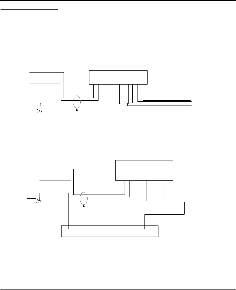
System Grounding Baldor drivers are designed to be powered from standard single phase lines
that are electrically symmetrical with respect to ground. System grounding is an
important step in the overall installation to prevent problems. The recommended
grounding method is shown in Figure 3-1 for UL compliant systems (Figure 3-2 for
CE compliant systems).
Figure 3-1 Recommended System Grounding for UL
L
AC Main
Supply
Safety
Ground
Driven Earth
Ground Rod
(Plant Ground)
L
N
Earth
N
Route all 3 wires L, N, and Earth
(Ground) together in conduit or
cable.
Note:
Wiring shown for clarity of grounding
method only. Not representative of
actual terminal block location.
Microstepper Driver
Ground per NEC and Local codes.
Note: Use shielded cable for driver signal wires. Route driver signal wires in
conduit. These wires must be kept separate from power and motor wires.
Linear
Motor
GND B+A–B–A+
Figure 3-2 Recommended System Grounding (1 phase) for CE
Note:
Wiring shown for clarity of
grounding method only. Not
representative of actual
terminal block location.
B+A–B–
Route all power
wires together in
conduit or cable.
Note: Use shielded cable for driver signal wires. Route driver signal wires in
conduit. These wires must be kept separate from power and motor wires.
Enclosure Backplane (see Section 8)
Motor
GND
All shields
LN
Linear
Motor
Microstepper Driver
AC Main
Supply
Safety
Ground
Driven Earth
Ground Rod
(Plant Ground)
N
Earth
A+
L
GND

Receiving & Installation 3-3MN1854
System Grounding Continued
Ungrounded Distribution System
With an ungrounded power distribution system it is possible to have a continuous
current path to ground through the MOV devices. To avoid equipment damage, an
isolation transformer with a grounded secondary is recommended.
Input Power Conditioning
Certain power line conditions must be avoided. An AC line reactor or an isolation
transformer may be required for some power conditions.
•If the feeder or branch circuit that provides power to the driver has
permanently connected power factor correction capacitors, an input AC
line reactor or an isolation transformer must be connected between the
power factor correction capacitors and the driver.
•If the feeder or branch circuit that provides power to the driver has power
factor correction capacitors that are switched on line and off line, the
capacitors must not be switched while the driver is connected to the AC
power line. If the capacitors are switched on line while the driver is still
connected to the AC power line, additional protection is required. TVSS
(Transient Voltage Surge Suppressor) of the proper rating must be
installed between the AC line reactor or an isolation transformer and the
AC input to the driver.
Power Disconnect A power disconnect should be installed between the input power service
and the driver for a fail–safe method to disconnect power. The driver will remain in
a powered-up condition until all input power is removed from the driver and the
internal bus voltage is depleted.
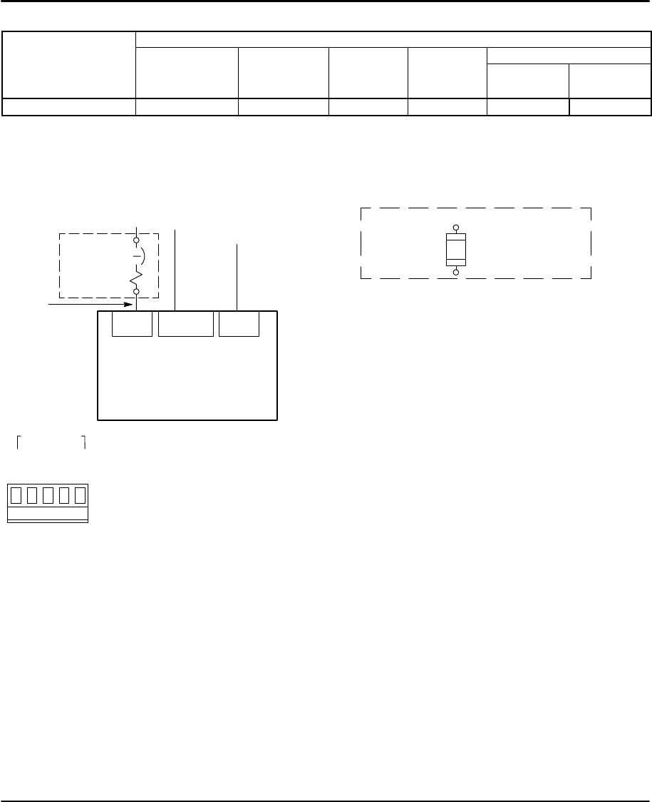
Protection Devices The driver must have a suitable input power protection device installed.
Input and output wire size is based on the use of copper conductor wire rated at
75 °C. Table 3-1 describes the wire size to be used for power connections and the
ratings of the protection devices. Use the recommended circuit breaker or fuse
types as follows:
Circuit Breaker: 1 phase, thermal magnetic.
Equal to GE type THQ or TEB for 115 VAC
Time Delay Fuses: Buss LPN on 115 VAC or equivalent.
Recommended fuse sizes are based on the following:
UL 508C suggests a fuse size of four times the continuous output
current of the driver.
Dual element, time delay fuses should be used to avoid nuisance trips
due to inrush current when power is first applied.
3-4 Receiving & Installation MN1854
Table 3-1 Wire Size and Protection Devices
Incoming Power
Continuous Input Input Fuse Wire Gauge
Catalog Number Nominal Input
Voltage
Continuous
Output
Amps (RMS)
Input
Breaker
(A) Time
Delay (A) AWG
(USA) mm2
(Europe)
LX2P1A06 115V (1f)6.0A 20 20 14 2.5
Note: All wire sizes are based on 75°C copper wire. Higher temperature smaller gauge wire may
be used per NEC and local codes. Recommended fuses/breakers are based on 25°C
ambient, maximum continuous driver output current and no harmonic current.
Power Connections Power connections are shown in Figure 3-3.
Figure 3-3 115VAC Single Phase AC Power Connections
Notes:
1. See “Protection Devices” described in this section.
2. Metal conduit or shielded cable should be used. Connect
conduits so the use of a Reactor or RC Device does not
interrupt EMI/RFI shielding.
3. Use same gauge wire for Earth ground as is used for L and N.
(VDE (Germany) requires 10mm2 minimum, 6AWG). For CE
Compliance, connect Earth to the backplane of the enclosure.
4. Reference EMC wiring in Section 8.
5. GND is located on the motor terminal strip.
L1
Alternate *
Fuse
Connection Note 1
L1 Neutral
Line Neutral
* Circuit
Breaker
Earth
Note 2
Note 1
Baldor
LinStep+
Note 3 & 4
* Components not provided with driver.
Earth
Note 5
RPack
Line
RPack
Neutral
Earth
Power 110VAC
Connector location is shown in Figure 3-4.
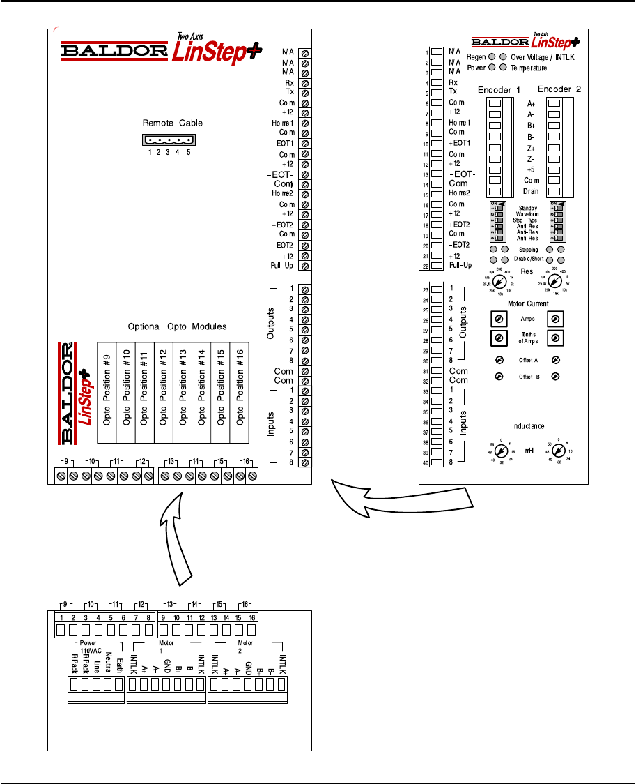
Receiving & Installation 3-5MN1854
Figure 3-4 Connection Locations (115VAC, 2 Axis)
Side Connections
Bottom Connections
3-6 Receiving & Installation MN1854
RS232/Keypad Installation Procedure: (optional keypad – LXKP)
Optional Remote Keypad Installation
The keypad may be remotely mounted and sealed to NEMA 4 specification by
using the gasket and 6 ft (1.8m) cable included. The keypad assembly is
complete with the screws and gasket required to mount it to an enclosure. The
gasket has adhesive on one side that must be placed toward the enclosure.
Tools Required:•Center punch.
•3/16" drill bit (for clearance mounting holes).
•1/2" (12.7) and 1-1/2" (38.1) standard knockout punch.
•(4) 6-32 nuts and washers (or M3.5 hardware).
•Remote keypad mounting template. A tear out copy is
provided at the end of this manual for your convenience.
Mounting Instructions: (see remote keypad mounting template)
1. Locate a flat mounting surface. Material should be sufficient thickness (14
gauge minimum).
2. Place the template on the mounting surface or mark the holes as shown.
3. Accurately center punch the 4 mounting holes (labeled E for SAE or M for
metric) and the three large Cut–Out holes.
4. Drill four 3/16" holes (at E or M).
5. Make the three large Cut–Out holes using the punch manufacturers instructions.
6. Debur knockout and mounting holes making sure the panel stays clean and flat.
7. Apply the adhesive backed gasket to the enclosure.
8. Assemble the keypad to the panel. Non–conductive screws and washers
should be used to electrically isolate the keypad from the enclosure.
Caution: To prevent keypad damage, be sure keypad mounting screws
do not extend more than 0.2 (5) into keypad assembly.
9. Connect the keypad cable to the “Remote Cable” connector, Figure 3-4.
Figure 3-5 Keypad (Nullmodem) Connections
Keypad
LinStep+
RS232 / Keypad
Connector
+5VDC
Rx
Tx
GND
Shld
Note: A 6ft (1.8m) cable is provided with the keypad. If a longer cable is
to be used, an external +5VDC @ 500mA power supply is required.
GND
N/C
Keypad
LinStep+
RS232 / Keypad
Connector
+5VDC
Rx
Tx
GND
Shld
+5VDC
Tx
Rx
Standard Connections External +5VDC
Connections
+5VDC
GND
GND
N/C
+5VDC
Tx
Rx
External
P.S.
Receiving & Installation 3-7MN1854
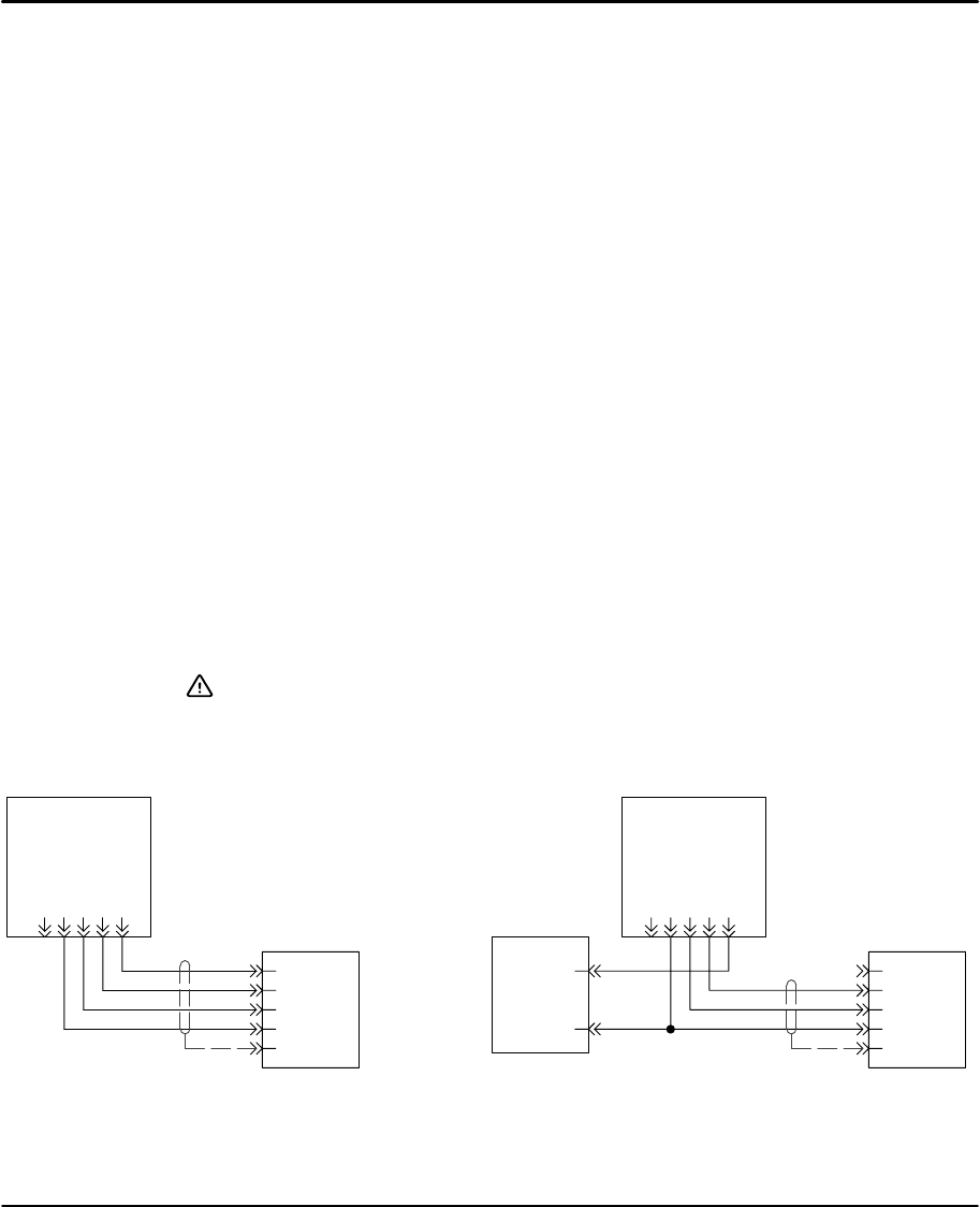
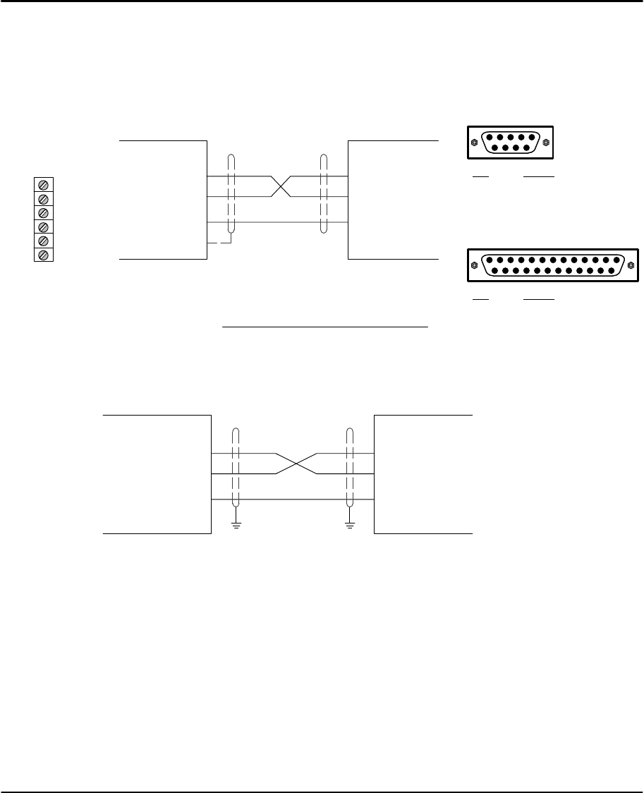
RS–232 PC Connections
A null modem connection must be made between the LinStep+ and the computer
COM port. This will ensure that the transmit and receive lines are properly
connected. Either a 9 pin or a 25 pin connector can be used at the computer,
Figure 3-6. Maximum recommended length for RS232 cable is 6 ft. (1.8 meter).
Figure 3-6 9 & 25 Pin RS-232 Cable Connections for UL Installations
25 Pin Connector
9 Pin Connector
Pin Signal
2 RXD
3 TXD
7 GND
Pin Signal
2 RXD
3 TXD
5 GND
LinStep+
(DCE)
Computer
COM
Port
(DTE)
RXD– 4
TXD – 5
Com – 6
RXD
TXD
GND
RS232 Connector
Chassis
If required, RTS, CTS, DSR and DTR may also
be connected for a full null modem connection.
Jumper 9 Pin 25 Pin
RTS to CTS
DSR to DTR 7 to 8
4 to 6 4 to 5
6 to 20
Tx
Com
N/A
Rx
N/A
N/A
Connector location is
shown in Figure 3-4.
Figure 3-7 9 & 25 Pin RS-232 Cable Connections for CE Installations
Control
(DCE)
Computer
COM
Port
(DTE)
RXD
TXD
GND
RXD
TXD
GND
PE PE
RS232 Connector
Note: For CE installations, connect the overall shield at each end of the cable to
PE. The voltage potential between the PE points at each end of the cable
must be Zero Volts.
3-8 Receiving & Installation MN1854
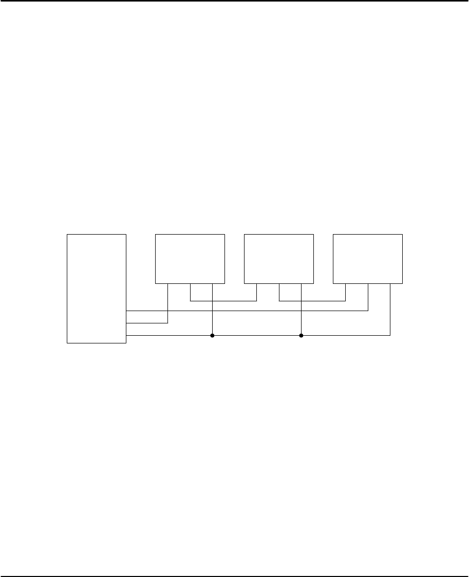
Daisy Chain Connections
LinStep+ can support daisy chaining. The unit address (range 1–99) can be set
with the keypad, through Application Developer, or with a terminal program using
the Unit Number (UN) command, or the entire chain may be addressed at once
using the Auto–Address (AA) command. Connect as shown in Figure 3-8.
Rules for Daisy Chain Operation
1. All LinStep’s in a daisy chain must have their device address assigned in
ascending order away from the host device. This allows the Load All (LA
– EX) commands to work properly. Addresses do not have to be
sequential, but must be in ascending order.
Example: 1, 2, 4, 6, 8 is valid addressing. 6, 3, 10, 8, 2 is not valid.
2. Do not duplicate unit addresses.
3. RS–232C “Echo” should be turned on for each unit in the daisy chain.
Disabling RS–232C Echo will prevent daisy chain operation.
4. All RS–232C connections must be correctly made.
5. “Device Addressing” RS–232C commands (for a specific LinStep+
device) must have the correct address specified in the command.
6. Status commands require the correct address.
Figure 3-8 Daisy Chain Connection
PC / Host
Device
RXD
TXD
GND
LinStep+
Unit 1
RXD TXD GND
LinStep+
Unit 2
RXD TXD GND
LinStep+
Unit 3
RXD TXD GND
Receiving & Installation 3-9MN1854
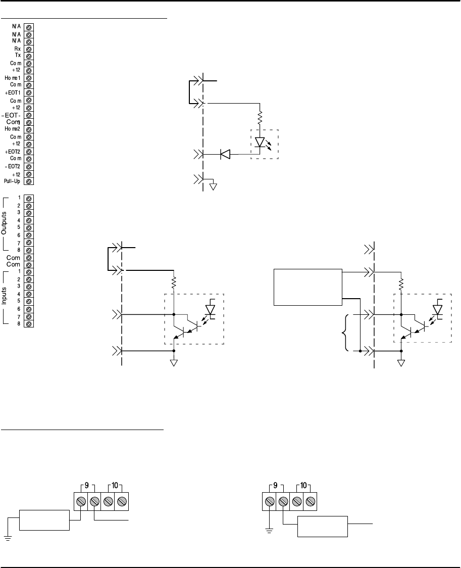
Programmable I/O Connections
These input connections are made at terminals 6–40 (Figure 3-4).
Note: Factory installed jumpers are at locations 9–10, 13–14, 18–19, 19–20 and
21–22.
Figure 3-9 Programmable Input Connections
EOT1 & 2, Home1 & 2
and Inputs 1–8 (33–40)
(Programmable) Opto Isolator
Common (Isolated)
1kÙ
Factory
Installed
Jumper
12V
P–Up
21
22
Maximum current = 35mA each input,
250mA maximum total from 12VDC
internal source.
Com 32
Figure 3-10 Programmable Output Connections
Outputs 1–8
(23–30)
(Programmable)
10kÙ
Opto
Isolator
12V
Factory installed jumper for 12VDC pull–up operation.
Maximum current sink capability is 100mA per output
and 350mA maximum from internal 12VDC supply.
P–Up
21
22
Maximum sink current = 100mA each
output, 250mA maximum total from
12VDC internal source.
Common
(Isolated)
Com 31
Factory
Installed
Jumper
Outputs 1–8
(Programmable) Com
10kÙ
Opto
Isolator
(Remove Jumper) 12V
P–Up
External
+24VDC
Supply
+24V
Com
Optional 24V Output Connections
Remove factory installed jumper from terminal P–Up.
Connect an external 24VDC supply to terminals P–Up
and Com. (Terminal P–Up must be positive).
Optional Opto I/O Connections
8 Optically isolated I/O connections are located at terminals 9–16 of Figure 3-4.
Connections to these terminals are shown in Figure 3-11 (if the optional Opto
Modules are used).
Figure 3-11 Opto Isolated I/O Connections
User Output
Circuit AC or +DC voltage source
Typical connection (each input)
User Load
Circuit AC or +DC
voltage source
Typical connection (each output)
3-10 Receiving & Installation MN1854
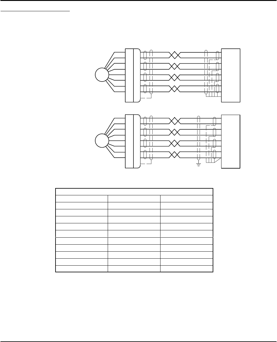
Encoder Connections (Refer to MN1800 for wire color and lead information.)
The location for each encoder connector (Side Panel) is shown in Figure 3-4.
Twisted pair shielded wire with an overall shield should be used. Figures 3-12 and
3-13 show the connections between the encoder and the encoder connector.
Figure 3-12 Differential Encoder Connections for UL Installations
A+
A–
B+
B–
+5V
Com
Encoder C+ (Index)
C– (Index)
Shell (Chassis)
A+
A–
B+
B–
+5V
Com
Z+
Z–
Drain
Figure 3-13 Differential Encoder Connections for CE Installations
Encoder
PE
Connection of shields to digital ground is optional.
A+
A–
B+
B–
+5V
Com
C+ (Index)
C– (Index)
Shell (Chassis)
A+
A–
B+
B–
+5V
Com
Z+
Z–
Drain
Table 3-2 Encoder Color Code
Encoder
Signal PVS100 Danaher (9–Pin D)
A+ White Green 6
A–Gray Yellow 1
B+ Orange Blue 8
B–Red Violet 3
Z+ (Index) N/A Red 9
Z– (Index) N/A Orange 5
+5VDC Black Brown 7
GND Brown Black 2
Inner shield Blue –4
Outer shield Violet –Shell
Receiving & Installation 3-11MN1854
Motor Connections The A+, A–, B+ and B– phase outputs of each axis provides power to the
motor windings. The location for each motor connector (Bottom Panel) is shown
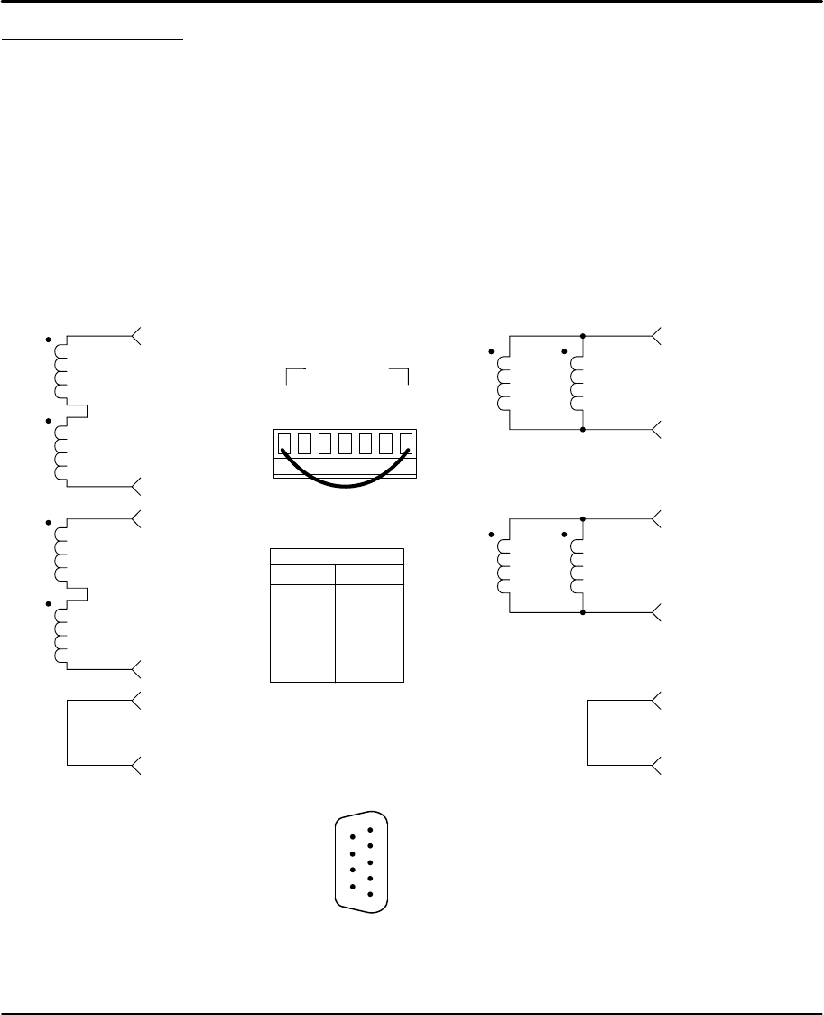
in Figure 3-4. The motor windings can be connected in series or parallel as shown
in Figure 3-14. For Baldor motors, refer to MN1800 for lead information.
Interlock (INTLK)
The two INTLK pins for each motor connector must be jumpered for the drive to
apply power to the motor. If an interlock wire breaks, or the connector is removed,
motor current is immediately stopped, the drive faults (latched) and flashes the
dual function LED labeled Over Volt./INTLK. Interlock wires longer than 5 inches
can create shutdowns due to noise.
Ground (GND)
GND is internally connected to the Earth pin on the Power connector. This provides
a convenient terminal for grounding the motor frame and a motor cable shield.
Figure 3-14 Stepper Motor Connections
B–
B+
A–
A+
INTLK
INTLK
Series Motor Connections
B–
Parallel Motor Connections
B+
A–
A+
INTLK
INTLK
Motor
Color Phase
White
Red
Green
Orange
Black
A+
A–
B+
B–
GND
(Refer to MN1800 for wire
color and lead information.)
Motor
Connector
INTLK
INTLK
A+
A-
GND
B+
B-
Motor X
INTLK jumper must be installed.
LD9068A00 Leadwire Connection (9 pin to flying leads)
1
2
3
4
5
6
7
8
9
Female (D Sub)
Color Pin# Description
Red 1 A+
Green 2 A–
Yellow 3 B+
Orange 4 B–
Black 5 Ground
Blue 6 A+
Green 7 A–
White 8 B+
Black 9 B–
When a D Sub connector is used, use the pin
numbers to connect the forcer.
When flying leads are used, use the color codes
to connect the forcer.
Use twisted pairs, shield open at backshell.
Section 1
General Information
3-12 Receiving & Installation MN1854
Start-Up Procedure
Power Off Checks
Before you apply power, it is very important to verify the following:
1. Verify the AC line voltage at the source matches the control rated
voltage.
2. Inspect all power connections for accuracy, workmanship and tightness.
3. Verify that all wiring conforms to applicable codes.
4. Verify that the control and motor are properly grounded to earth ground.
5. Check all signal wiring for accuracy.
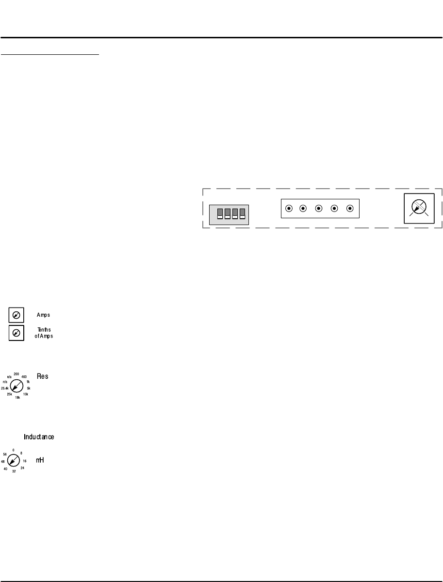
6. Set Keypad DIP switches as desired, Figure 3-15. (Power must be
cycled after a DIP switch position change).
Figure 3-15 Keypad Adjustments
1234
ON
5
N/C
4213
GND Rx Tx +5VDC
DIP Switch Keypad Operation
12
Off Off Full Keypad Operation
Off On No access to Run, ESC, Edit, Copy, Del
On Off No access to Run, Edit, Copy, Del
On On No access to Edit, Copy, Del Switches 3 and 4 are reserved.
Switch and Potentiometer Settings
The motor current, inductance, and resolution settings must be made before
power is applied. The other settings (waveform, standby current, anti–resonance,
and phase offset adjustments can be made while the drive is powered and the
motor is moving.
Motor Current (can be changed at any time)
Set these switches for the correct values for the motors connected to each
axis. The Motor Current range is 0.0–6.0 Amps (peak) per motor phase per axis.
Each axis has two, 10–position rotary switches (labeled Amps and Tenths of Amps
in Figure 3-4). These switches set the current for each motor. The top switch sets
the integer current value, and the bottom switch sets the tenths of amps value.
Motor Resolution (only read at power up, cycle power if changed)
Eight selectable motor resolutions (200, 400, 1,000, 5,000, 10,000, 18,000, 25,000
and 25,400 steps) are available. Rotary switches (“Res” shown in Figure 3-4) set
the resolution for each axis motor. Motor Resolution may be selected using these
switches or configured with the keypad (or by serial commands). This resolution
setting assumes you are using a step motor with 1.8 degree per full step.
Motor Inductance (can be changed at any time)
Motor Inductance is set by a 16–position rotary range switch (Side Panel of Figure
3-4). The inductance switch has settings from 0 to 60 mH, in multiples of 4 mH.
For the proper setting, round motor inductance to the nearest multiple of 4 mH.
If the exact inductance of the motor is not known, initially set the inductance to
8mH. The inductance switch is more of an adjustment than a setting. If the setting
is too low, the motor will stall. If the setting is too high an audible hum will be heard
from the motor, and increase motor heating. Between these two extremes is
generally 2 or 3 correct inductance settings.

Receiving & Installation 3-13MN1854
Standby Current (can be changed at any time)
Setting the Standby current DIP switch to ON reduces motor current by 30% when
the drive has not received a step pulse for 250 msec. Full current is restored when
the next step pulse is received. Each drive can also be set to standby with the EA2
software command.
A 30% reduction in motor current during Standby correlates with an approximate
30% reduction in motor holding torque. Do not use Standby mode in applications
where you need more than 70% of the motor’s torque to hold a load stationary.
Standby should not be used in applications where an encoder is used to perform
end–of–move position maintenance.
Waveform (can be changed at any time)
On Sinusoid, Off for 4% 3rd harmonic.
Step Type (can be changed at any time)
Not Used.
Anti–Res (can be changed at any time)
Not Used.
Power On Checks
When power is first applied, the “ON” LED will be green. With the keypad
connected, the LCD display will briefly display the initialization screens.
Note: The LCD display may require contrast adjustment for better viewing. If the
display cannot be seen, adjust the potentiometer in Figure 3-15 for best
viewing.
Action Display Comments
Apply Power. +0.0000
00000000 00000000
Power–up diagnostic display. No errors.
The motor should now be producing torque.
Action Display Comments
Select “RUN, JOG (F2)”.JOG AXIS +0.0000
<LO> HIGH
Select either Low or High to Jog the
motor position. Confirm proper motor
operation.

3-14 Receiving & Installation MN1854
Section 4
Keypad Operation
Keypad Operation 4-1MN1854
Overview (Firmware versions LinStep+ Dual B3.1; Keypad V2.90; FPGA#1 7.1 #2 7.1))
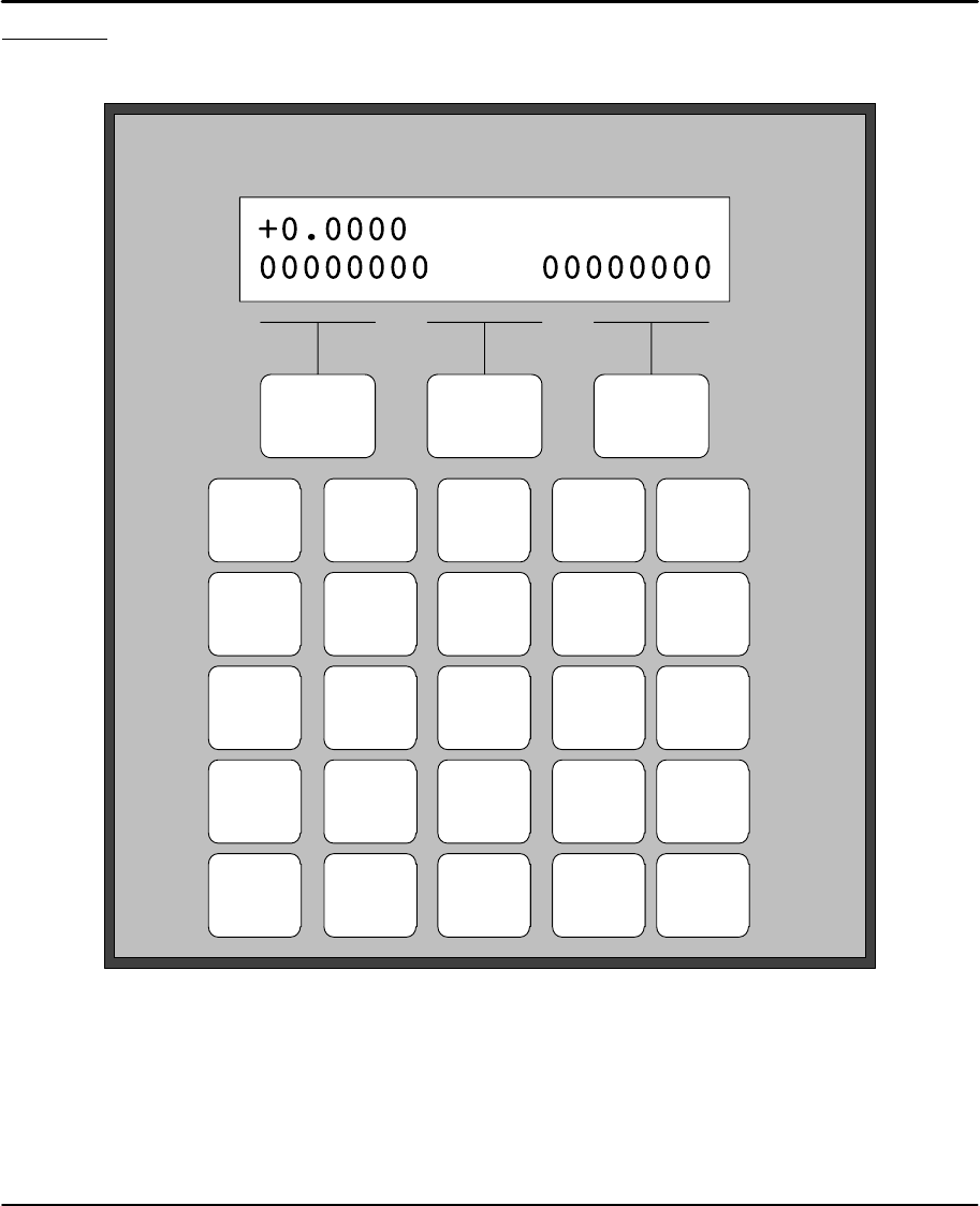
The Keypad layout with the LCD display is shown in Figure 4-1.
Figure 4-1 Keypad and LCD Display
F1 F2 F3
RUN EDIT HELP COPY DEL
1
ABC
2
DEF
3
GHI
4
JKL
5
MNO
6
PQR
7
STU
8
VWX
9
YZ
ESC 0
÷ * = ±ALPHA ENTER
,
.
←
↓
→
↑
VE
AC
DE
VE
AC
DE
GO
GH
GI
TD
OT
WT
LP
EB
IF
GT
GS
EN
MS
FK
IV
MC
ON
SP
CL
CT
ST
RG
( )
[ ]
F1, F2, F3
Selector keys. Used with numeric keys to select commands in the editor.
Programmable as operator menu selections. (See the FK command for
information on using the function keys within a program.)
Most operations are menu–driven. A menu consists of a title bar (top display line)
and as many as three options or sub–menus (bottom display line). Each option is
displayed above one of the function keys, F1, F2, or F3. Press a function key to
select the corresponding option. Table explains which menus are available.

4-2 Keypad Operation MN1854
Note: If a menu has more than three options, arrows on both sides of the display
indicate that more options are available. Press the appropriate arrow key to
display one option at a time. To exit a menu without making a selection, or
to back up one menu level, press ESC.
Table 4-1
Menu Key
RUN EDIT HELP COPY DEL
PROG (F1)
Run programs by
name or number.
PROG (F1)
Edit or write
programs.
In Main Menu:
Provides help on
the function of
RUN, EDIT, or
COPY.
PROGRAM (F1)
To copy programs
within a control
(source file>
destination file)
Deletes an entire
program or in
editor deletes
characters
Menu
JOG (F2)
Jog either axis at
low or high
speeds.
Press F1 or F2,
and
any arrow key
(←↑↓→).
SETUP (F2)
Configure system
components and
operating limits.
In Menus:
Provides help on
menus.
TO PAD (F2)
To upload data
from control’s
memory to the
keypad.
Menu
Options TEST (F3)
Run programs in
trace mode, do
amplifier
shutdown and
reset, and test
outputs or moves.
POS (F3)
Reset axis
position to zero?
YES NO
(F1) (F3)
In Sub–Menus:
Explains setup
choices.
FROM (F3)
To download data
from keypad
memory to a
control.
LIST (↓) (F1)
Directory of
stored programs,
memory usage
and available
space
In Editor:
Provides
command
descriptions.
RUN
Press RUN to start a program, Jog an axis, or access Test/Debug functions.
EDIT
Press Edit to change setup parameters and programs, list programs, & reset
position counter.
HELP
Provides help information for keys, menus, and command syntax.
COPY
Copies one program to another within the LinStep+.
DEL
Deletes characters in the editor, or deletes entire programs from memory.
0–9
Enters numbers. Used with ALPHA key to enter characters. Used with F1, F2, F3
keys to select commands in the program editor.
ESC
Press ESC to stop a program or to move back one menu level. In program editor,
it saves the program and exits the editor.

Keypad Operation 4-3MN1854
+
Selects the motion direction in program editor. May also be used in math
programs or equations.
u=O"
Cursor control keys that are used to scroll through menu choices in the editor.
Moves an axis in JOG mode.
Decimal Point
Used when entering fixed–point numbers.
Comma
Used in multi–axis programs to separate axis command parameters. Part of the
syntax in message and variable “prompt” commands.
Alpha
In the editor, allows entering alpha characters for the keypad.
ENTER
In the program editor, press ENTER to save parameters that have been typed.
Enters a space in the program editor mode.
Run Menu Pressing the RUN key displays a set of sub–menus.
PROG Access the sub–menus by pressing F1 (PROG), F2 (JOG), or F3 (TEST).
Action Display Comments
Press RUN key RUN
PROG JOG TEST
Select a sub–menu, press F1 (PROG),
F2 (JOG), or F3 (TEST).
Press F1 (PROG) to run (or
execute) an existing program
number.
OR
↑RUN PROGRAM↓
>5
Use the numeric keys to enter a
program number to run (example, 5 and
press ENTER).
Press F1 (PROG) select an
existing program to run. ↑RUN PROGRAM↓
>12 GRIND
Use the keys to scroll through the list
of programs. Press ENTER to select
the program.
JOG Pressing the RUN key displays a set of sub–menus. Press F2 (JOG).
Action Display Comments
Press RUN key RUN
PROG JOG TEST
Press F2 (JOG) to JOG the
motor.
OR
JOG AXIS 1 +0.0000
<LO> HIGH
Use the ←↑↓→ keys to JOG the motor.
Press F1 <LO> or F2 HIGH speed.
Use the 0–9 keys to enter the
desired JOG distance. JOG AXIS 1 +0.0000
Dist: .012
Press and release an arrow key to
make the motor move this distance.
The arrow pressed determines the
direction of the move. Press and
release an arrow key to move the motor
again. Press ESC to terminate JOG.
Note: Jog speed and acceleration are changed in the “EDIT, SETUP, JOG” menu.

4-4 Keypad Operation MN1854
Test The RUN > TEST > RS232 feature has now been implemented which allows for
testing and debugging of daisy chain terminal communications through the keypad
thus eliminating the need for a PC terminal connection.
Action Display Comments
Press RUN key RUN
PROG JOG TEST
Select a sub–menu, press F1 (Prog),
F2 (Jog), or F3 (Test).
Press TEST for sub menu
selections. ↑RUN TEST↓
TRACE OUTPUT MOVE
Select a sub–menu, press F1 (Trace),
F2 (Output), or F3 (Move).
Press ↑ or ↓key for more sub
menu selections. ↑RUN TEST↓
SHUTDN RS232 ENCODER
Select a sub–menu, press F1
(Shutdown), F2 (RS232), or F3
(Encoder).
STrace – Allows program execution in trace mode (debug or
troubleshoot).
SOutput – Test outputs 1–16 or 17–32.
SMove – Allows motion for axis 1 or 2 or both.
SShutdown – Allows Amp 1 or 2 to be Enabled, Disabled or Reset.
SRS232 – Allows transmit (”ABC123”) and receive testing. This allows
test and debug of daisy chain communications using the keypad instead
of a PC.
SEncoder – Allows encoder 1 or 2 testing (Disable, OneRMov or Find Z).

Keypad Operation 4-5MN1854
Edit Menu Pressing the EDIT key displays a set of sub–menus.
Action Display Comments
Press EDIT key –↑EDIT↓–
PROG SETUP POS
Select a sub–menu, press F1 (PROG),
F2 (SETUP), or F3 (POS).
Press ↑ or ↓key for more sub
menu selections. –↑EDIT↓–
LIST
Select a sub–menu, press F1 (LIST).
Edit, PROG Submenu Create A New Program
1. Press “EDIT, F1 (PROG)” and you will see a display with a blinking
cursor as shown in Figure 4-2.
Figure 4-2 New Program
–↑EDIT PROGRAM↓–
>_
2. Enter an unused identifying number for the program (between 1–400).
(If several programs are stored, you may need to scroll the list to
determine a number that has not been used. )
Note: You may assign a name, rather than a number, to your program if you wish.
See “Naming Your Programs” later in this section.
3. Press ENTER. You will see a blank screen with a blinking cursor in the
upper left corner. The program editor is now ready to accept a program.
4. Once inside the program editor, enter commands by pressing a function
key and then a numeric key. Examples of creating, saving, naming, and
editing programs follow.
Example of entering programming commands found on the #2 key, Figure 4-3.
STo enter the VE command (the upper command on the number 2 key),
press F1 (blue) then press the number 2 key.
STo enter the AC command (the middle command on the number 2 key),
press F2 (yellow) then press the number 2 key.
STo enter the DE command (the lower command on the number 2 key),
press F3 (green) then press the number 2 key.
Figure 4-3
2
DEF VE
AC
DE

4-6 Keypad Operation MN1854
Example of entering a program using the 0–9 keys. To create a program with the
commands “AC.3 VE2 DI1 GO”, do the following steps: (you must be in the
program editor, this example is writing to program #2).
1. Press EDIT→F1→2→ENTER to get to the first line of program 2.
2. Press F2, then press the #2 key. This will enter the AC command.
3. Press the decimal key.
4. Press the #3 key.
5. Press ENTER. This will insert a space after the 3 to separate the
commands.
6. Press F1, then press the #2 key. This will enter the VE command.
7. Press the #2 key.
8. Press ENTER. This will insert a space after the 2 to separate the
commands.
9. Press F2, then press the #1 key. This will enter the DI command.
10. Press the #1 key.
11. Press ENTER. This will insert a space after the 1 to separate the
commands.
12. Press F1.
13. Press the #3 key. This will enter the GO command.
14. Press ENTER.
15. The display should now show the program “AC.3 VE2 DI1 GO”.
Save the program
When you have completed the program, and the display shows the program
“AC.3 VE2 DI1 GO”, do the following:
1. Press ESC, the menu of Figure 4-4 is then displayed.
2. Press F1 (YES) or F3 (NO).
Figure 4-4
Save Program?
Yes No
Edit an existing program
1. Press “EDIT, F1 (PROG)” and you will see a display with a blinking
cursor as shown in Figure 4-5. Enter the name of the program you wish
to edit or scroll the list to locate the program.
Remember, ENTER inserts a space (delimiter). DEL deletes a character.
Use the cursor keys to scroll through the program one line at a time.
Figure 4-5
–↑EDIT PROGRAM↓–
>_

Keypad Operation 4-7MN1854
Naming a program
A program can be given a descriptive name in addition to the program number that
the LinStep+ assigns it. Program names must be put inside of square brackets,
[program name], at the start of a program. The name can be up to 14 characters,
but the first 10 must be unique. Like variables, the name can be any combination
of characters.
Programs or subroutines are often named to help “self document” a program. It is
usually easier to remember and understand a name than a number. You may call
or branch to a program by name.
Suppose your program has 20 different parts and each part has a different
program name. Simply name each program so an operator will easily recognize
them. When the keypad RUN key is pressed, instead of entering a number, simply
scroll through the list of program names until the desired program is displayed.
Then press ENTER to run the program.
Example of Naming a Program
Add a name [MINE] to the program.
To insert [MINE]:
1. Press F3.
2. Press 0 (zero) key. Insert brackets.
3. Press ALPHA. Move to next character.
4. Press #5 key. Insert M.
5. Press ALPHA. Move to next character.
6. Press #3 key three times. Insert I.
7. Press ALPHA. Move to next character.
8. Press # 5 key two times. Insert N.
9. Press ALPHA. Move to next character.
10. Press #2 key two times. Insert E.
11. Press the → key to move cursor to the right of the bracket. The program
name will be as shown in Figure 4-6.
Figure 4-6
[MINE] AC.3 VE2 DI1 GO
12. Press ESC. You will be prompted as shown in Figure 4-7.
Figure 4-7
Save Program_?
YES NO

4-8 Keypad Operation MN1854
Entering Characters with the Alpha Key (In edit mode)
The ALPHA key allows you to enter almost any character into a program from the
keypad. This is useful to name your programs or subroutines, call subroutines by
name, make variable names descriptive, use operator messages or prompts, send
messages over RS–232 port or use commands not on the keypad, such as EA
or “ ”.
The letters are found on the 0–9 keys. To insert A, B or C on the #1 key:
1. Press ALPHA.
2. Press the numeric key with the character you want. (In this example,
press the #1 key once to select A, press it twice to select B, and press it
three times if you want the C).
General Rules for Using The Alpha Key
S Any number, letter or character on the 0–9 keys can be placed in a program.
S Press a numeric key 4, 5 , and 6 times to access the lower case letters.
S Press ALPHA prior to each character you wish to enter.
S Press the
← or → key to move the cursor to the next space.
S Press ALPHA to move the cursor more than one space.
Use the =O keys for additional alpha characters.
The 19 special characters shown to the right are available by pressing ALPHA and
scrolling through the list using the arrow keys.
1. Press ALPHA.
2. Press ↑ or ↓ to scroll through the list of characters.
3. When the desired character is displayed, press ALPHA or ENTER to
enter the character. The character will be displayed and the cursor will
move one space to the right.
4. Press ESC to leave the editor. The list of characters is shown in Figure
4-8.
Figure 4-8 Alpha Characters
< > ? ! @ # % & _ :
; \ ′ ″ |↑ ↓ ← →

Keypad Operation 4-9MN1854
Edit, Setup Submenu Table 4-2 shows the structure within the “EDIT, SETUP” submenu.
Table 4-2 Edit, Setup Submenu
Submenu Setup Parameter Description of Setup Parameter
TYPE Motor parameters
MOTOR D–RES Drive resolution
MOTOR DIR Direction of travel
MODE Select open/closed loop mode
E–RES Encoder resolution
FOL–ERR Following error
ENC IN–RANGE Position maintenance window
PMGAIN Position maintenance gain
PMMAX Position maintenance maximum velocity
DIST Distance Units
PITCH Motor pitch 40mil or 20mil (40mil is factory setting)
VEL Speed units
MECH VMAX Critical speed limit
ACCEL Acceleration units
AMAX Maximum rate of acceleration
INPUTS Input functions
OUTPUTS Output functions
I/O OPTOS OPTO module configuration
I/O OUTSTS Configure output states during Powerup, Fault, and Stop/Kill command.
LIMITS Configure EOT polarity (N.O. or N.C.)
ACCEL Jog acceleration
JOG LO–VEL Low jog velocity
JOG
HI–VEL High jog velocity
ENABLE Enable/disable jog in RUN menu
MODE Homing method
EDGE Edge of home switch
HOME SWITCH Type of home switch
HOME OFFSET Position counter offset
DIR Final homing direction (positive or negative)
PWR–UP Program to run on power up, if any
PROG SCAN How to scan program select inputs
PROG DELAY Program Select de–bounce time
RS–232C ECHO Echo characters
RS–232C
UNIT# Serial address
DISP Display mode (not currently implemented)
MISC STOP–RATE Decel rate when stop input activated
MISC
TEST Enable Test Menu (not currently implemented)
PASWRD Password setup for operator/administrator access

4-10 Keypad Operation MN1854
Edit, POS Submenu Select “Edit, POS” to Reset the Current Position to Zero.
POS is a quick way to reset the motor’s present position to (absolute) zero – a
very useful setup and debugging tool.
Action Display Comments
Press “EDIT, POS” (F3) Reset Position?
YES NO
Press YES (F1) or NO (F3)
Edit, List Submenu Select “EDIT, ↓, LIST” to view memory usage.
LIST provides a way to view your program memory usage. Standard program
storage is 60K bytes, and the maximum size of a single program is 1,024 bytes.
LinStep+ will store up to 400 programs, with a maximum single program size of
1,024 bytes.
Action Display Comments
Press “EDIT, ↓, LIST” to
display the number of
programs stored.
DIRECTORY ↑MORE↓
PROGRAMS: 18
Press ↓to display the total
memory used for program
storage.
DIRECTORY ↑MORE↓
BYTES USED: 1186
Press ↓to display the total
free memory available. DIRECTORY ↑MORE↓
BYTES FREE: 4958
Press ↓continuously to scroll
through the list of programs,
displaying the number of bytes
used by each program.
DIRECTORY ↑MORE↓
5<untitled>: 56 bytes

Keypad Operation 4-11MN1854
HELP Menu Press HELP to display a help message related to the menu. Help messages are
often several lines, which you can scroll through using the ↓ and ↑ keys. When
you are finished reading a help message, press ESC to return to the menu.
Pressing HELP in the Main Menu
HELP explains the functions available when you press any of the non–numeric
keys.
Pressing HELP in Menus and Sub–Menus
HELP explains the selections available from your current menu location.
Pressing HELP In the Program Edit function
HELP provides a brief, alphabetical list of commands.
Note: A program must be selected to view the COMMAND SUMMARY.
COPY Menu Pressing the “COPY” key displays three submenu choices.
Action Display Comments
Press the “COPY” key – – – COPY – – –
PROG TO PAD FROM
Select a sub–menu, press F1 (PROG),
F2 (TO PAD), or F3 (FROM).
COPY, PROG Submenu Copy one program to another program.
Action Display Comments
Press F1 (PROG) to copy from
a program. ↑SOURCE PROGRAM↓
>5
Enter the source program number.
Or, if you wish, you can scroll
through your list of program names.
Press ENTER when finished.
Enter the new program
number. ↑TARGET PROGRAM↓
>6
If the target program exists, you
must first delete it (see DEL).
Press ENTER when finished.
Note: Remember to change the name of the copied programs to avoid subroutine
call conflicts.
COPY, TO PAD Submenu Copy a program to the keypad from LinStep+ or a PC.
Action Display Comments
Press F2 (TO PAD). Two
messages are displayed
sequentially.
Receiving From Drive Copies a program from LinStep+ to
the keypad. When the “Saving To
EEPROM” message disappears,
sequentially.
Saving To EEPROM
may take 40 seconds
EEPROM” message disappears,
the program has been stored in
keypad memory.

4-12 Keypad Operation MN1854
COPY, TO PAD Submenu Continued
To copy a program from a PC to the keypad, connect the keypad to the RS232
port of the PC (COM1 or COM2). Start the Application Developer software and
from the Communications menu, click on “Send All”. The keypad will display the
message “Receiving From PC” and a few more messages will quickly appear, then
disappear from the screen. When the keypad display is blank, the transfer is
complete.
COPY, FROM Submenu Copy a program from the keypad to the LinStep+ or to a PC.
Action Display Comments
Press F3 (FROM). Four
messages are displayed
sequentially.
Receiving From EEPROM Copies a program from the keypad to
LinStep+. When the “Saving To
Memory” message disappears, the
Sending To Drive
transfer is complete.
Waiting For Processing
Saving To Memory
To copy a program from the keypad to a PC, connect the keypad to the RS232
port of the PC (COM1 or COM2). Start the Application Developer software and
from the Communications menu, click on “Retrieve All” and choose “From
Keypad”. The keypad will display the message “Sending to PC” and a few more
messages will quickly appear, then disappear from the screen. When the keypad
display is blank, the transfer is complete.
DEL Menu The DEL (Delete) key allows you to delete any motion program.
Action Display Comments
Press the DEL key. ↑DELETE PROGRAM↓
>6
Enter the program number. Or, if
you wish, you can scroll the list of
program names.
Press ENTER when finished.
DELETE PROGRAM #6
YES NO
Press F1 to delete program or F3 to not
delete the program.
DEL is also used to delete text or numeric characters in the editor. Use the cursor
control keys to move over the character you wish to delete, then press DEL.
Section 5
Setup
Setup 5-1MN1854
Overview There are two ways to setup the parameters: use the keypad or use Intelliware
serial communications software. The procedures presented in this section allow
LinStep+ to be configured using the keypad (LXKP). If you are not familiar with
the operation of the keypad, please refer to Section 4 of this manual. To ensure
that LinStep+ is correctly configured, follow all the procedures so that important
parameters are not overlooked.
Intelliware software (serial communications) users can refer to this section for
definition of the configuration parameters. The Windows dialog boxes follow the
keypad menu structure very closely. Details of Intelliware software are provided in
MN1855.
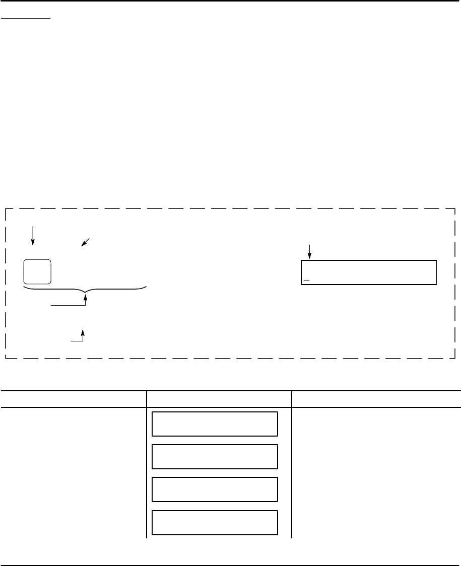
Procedure Format Definition
The 2–character ASCII command appears in brackets next to the keypad
command. This is the Intelliware software command. Configuring LinStep+ to a
specific application requires customizing a number of software parameters to
match the mechanics of the system. These parameters include motor, encoder,
distance, acceleration and velocity scaling, I/O, jog, home, and serial
communication.
Sample format of a procedure description:
Parameter being Configured
Definition [ ID ]
ASCII Command (Intelliware)
EDIT > SETUP > I/O > INPUTS
Keypad
Steps Value:
Range:
Factory Setting
and range of adjustment
IN1: unassigned:
BBBBKREJ
Keypad Display
Pressing the EDIT key displays a set of sub–menus.
Action Display Comments
Press EDIT key –↑EDIT↓–
PROG SETUP POS
Select a sub–menu, press F1 (PROG),
F2 (SETUP), or F3 (POS).
Press F2 (SETUP) key for more
sub menu selections. –↑SETUP↓–
PROG RS232 MISC
Select a sub–menu, press F1 (PROG),
F2 (RS232), or F3 (MISC).
Press ↓key for more sub menu
selections. –↑SETUP↓–
MOTOR ENC MECH
Select a sub–menu, press F1
(MOTOR), F2 (ENC), or F3 (MECH).
Press ↓key for more sub menu
selections. –↑SETUP↓–
I/O JOG HOME
Select a sub–menu, press F1 (I/O), F2
(JOG), or F3 (HOME).

5-2 Setup MN1854
Configure Motor Adjustments for resolution and movement direction can be made while the motor
is energized and moving or at rest.
Configuring Motor Type [ MT11 ]
EDIT > SETUP > MOTOR > TYPE > STEPER Axis One Motor Type
Steper
Note: Motor type is fixed, L–Step (Linear Steper) for both axes. Press ← or → to select next axis.
Configuring Motor Current [ MR10 ]
EDIT > SETUP > MOTOR > D–RES
Value: 25000
Range: 200, 400, 1000, 2000, 5000, 8000, 10000,
18000, 25000, 25400, 36000, 50000,
5120, 7120, 10240, 14240, 51200, 71168,
102400, 142400
– Axis One Drive Res –
25000
If you want moves in 0.1 degree increments, a D–RES of 18,000 will
allow 50 motor steps per degree and prevent any resolution–induced
rounding errors. Setting the drive resolution automatically adjusts the
pulse–width.
↑ or ↓to select value, press ENTER
Press ← or → to select next axis.
Configuring Motor Direction [ MDi ]
EDIT > SETUP > MOTOR > DIR
Value: Positive
Range: Positive or Negative
– Axis One Motor Dir –
POSITIVE
Provides a convenient way to change the motor direction for a positive distance
command. When POSITIVE is selected as the motor direction, the EOT+ limit
switch should be wired so that moves in the plus direction will activate the switch.
When NEGATIVE is selected, the EOT+ limit switch should be wired so that
moves in the negative direction will activate the switch.
↑ or ↓to select value, press ENTER
Press ← or → to select next axis.

Setup 5-3MN1854
Configure Encoder If you are not using an encoder, set encoder mode to OPEN LOOP and skip to MECH.
Configuring Encoder Mode [ EMi ]
EDIT > SETUP > ENC > MODE
Value: Open Loop
Range: Open Loop, Open–Stall,
Closed Loop, Closed Loop–PM
– Axis One ENC Mode –
–↑OPEN LOOP ↓–
↑ or ↓to select value, press ENTER
Press ← or → to select next axis.
Open Loop The OPEN LOOP position will be displayed on the keypad.
Open–stall The OPEN LOOP position will be displayed on the keypad, and the
encoder will be used for stall detection. (See Following Error)
Closed Loop The actual encoder position is displayed on the screen. All subsequent
moves are calculated from this actual position. All moves are based on
encoder pulses. Stall detection is enabled. Positioning resolution will
equal the resolution of your encoder.
Closed Loop–PM Same as closed loop except for the post move position maintenance of
the last commanded position. Provides a “pseudo–servo” operation for
a stepper system. Closed Loop–PM will not correct position while
navigating menus with the keypad.
Use PM GAIN, PM VMAX, and IN–RANGE WINDOW parameters to specify position
maintenance tuning parameters.
Application Notes:
Following–error is still active while in CLOSED LOOP–PM mode. A following–error will occur
when the number of correction steps exceeds the following error value. This allows the unit
to signal a fault when the displacement cannot be corrected, i.e. an obstruction. Ensure
proper operation in Open Loop mode before attempting Closed Loop–PM mode.
Configuring Encoder Resolution [ ERi ]
EDIT > SETUP > ENC > E–RES
Value: 5000 cnts/in
Range: 1–9,999,999
– Axis One ENCODER RES–
–↑5000 cnts/in ↓–
Select value, press ENTER
Press ← or → to select next axis.
This option sets the encoder resolution. The resolution is specified
in encoder pulses per in of travel, post–quadrature. To prevent
end–of–move dither, an encoder resolution of 8000 or less is recommended.

5-4 Setup MN1854
Configuring Following Error Limit [ FEi ]
EDIT > SETUP > ENC > FOL–ERR
Value: 750 Steps
Range: 0–99,999 motor steps (0 = Off)
– Axis One Fol Error –
–↑750 Steps ↓–
Select value, press ENTER
Press ← or → to select next axis.
If a Following Error occurs, the control will enter a fault state where:
SAny motion or program being executed is immediately terminated.
S The LCD Display will indicate “Following Error”, along with an
explanation.
S A fault output will be generated if defined as a “Stall” or Fault
output.
S The fault must be cleared before motion can occur. A Stop or Kill,
by programmable inputs or serial command, the ESC key or a
RESET will clear a Following Error fault
S Bit 9 of SS response is set to 1
S Bit 1 of SD response is set to 1
Configuring Position Maintenance In–Range Deadband [ IRi ]
EDIT > SETUP > ENC > IN–RNGE
Value: 25 Steps
Range: 0–32,767 steps
– IN–RANGE SETUP –
WINDOW
Select WINDOW (press F1)
In–Range Window specifies the position maintenance deadband or
region surrounding the set–point position. The “window” is specified in
post–quadrature (4 x # of lines) encoder steps. The window is the
region surrounding the commanded position in which the load reside
and not be considered “out of position.” The control will try to correct
the position if it is outside this window.
– IN–RANGE WINDOW –
←25 steps →
Enter encoder steps, Press ENTER
(must be a positive number)
Configuring Position Maintenance Gain [ PGi ]
EDIT > SETUP > ENC > PMGAIN
Value: 10
Range: 1–32,767
– Axis One PM GAIN –
←10 →
Select value, press ENTER
Press ← or → to select next axis.
PM Gain specifies a gain value used to determine correction velocity. The
correction velocity is calculated as “displacement* correction gain” in units
of steps/in. Therefore, the larger the displacement, the faster position
maintenance will attempt to correct position. For example, if the correction
gain is set to 3 and an active displacement of 3200 steps occurs, the
correction velocity will be (3 * 3200) = 9600 steps/sec.
Setup 5-5MN1854
Configuring Position Maintenance Max Velocity [ PVi ]
EDIT > SETUP > ENC > PMMAX
Value: 1.0 in/s
Range: 0.005–9,999,999.0
– Axis One PM MaxVel –
←1.0 in/s →
Limits the velocity of a position maintenance correction. Regardless
of the magnitude of displacement of correction gain, the correction
velocity will never exceed this maximum velocity setting.
Select value, press ENTER
Press ← or → to select next axis.
Configure Your Application (Mechanics)
The MECH SETUP menu allows you to preset distance, velocity, and acceleration
units convenient for your application. These units are used for all display and
position reporting modes. This menu also allows you to compensate for a known
amount of backlash in your mechanical system, and to set a maximum allowable
speed for each axis.
Action Display Comments
Press EDIT key –↑EDIT↓–
PROG SETUP POS
Select a sub–menu, press F1 (PROG),
F2 (SETUP), or F3 (POS).
Press F2 (SETUP) key for more
sub menu selections. Press ↓key
for more sub menu selections.
–↑SETUP↓–
PROG RS232 MISC
Select a sub–menu, press F1 (PROG),
F2 (RS232), or F3 (MISC).
Press F3 (MECH) key –↑SETUP↓–
MOTOR ENC MECH
Select a sub–menu, press F1
(MOTOR), F2 (ENC), or F3 (MECH).
Press ↓key for more sub menu
selections. ←↑ MECH SETUP ↓→
DIST Pitch Vel
Select a sub–menu, press F1
(Distance), F2 (Pitch), or
F3 (Velocity).
Press ↓key for more sub menu
selections. ←↑ MECH SETUP ↓→
VMAX ACCEL AMAX
Select a sub–menu, press F1 (VMAX),
or F2 (Accel), or F3 (AMAX).
Configuring the Distance Unit [ DUi ]
EDIT > SETUP > MECH > DIST
Value: inch
Range: inch or mm
– Axis One Dist Units –
←↑ inch ↓→
This sets the distance units and unit label. All distance values are
expressed in the units selected here.
↑ or ↓to select value, press ENTER
Press ← or → to select next axis.

5-6 Setup MN1854
Configuring Units of Velocity [ VUi ]
EDIT > SETUP > MECH > VEL
Value: in/s
Range: in/s or in/min
– Axis One Vel Units –
←↑ in/s ↓→
Sets the velocity units. All velocity values will be expressed in these units.
↑ or ↓to select value, press ENTER
Press ← or → to select next axis.
Configuring Maximum Velocity [ MVr ]
EDIT > SETUP > MECH > VMAX
Value: 500.0 in/s
Range: 0–9999999.0
– Axis One MAX Vel –
←↑ 500.0 in/s ↓→
Sets the top speed of your motor. (Limits the speed from LinStep+ to
prevent accidental damage to your mechanics.)
Select value, press ENTER
Press ← or → to select next axis.
Configuring Acceleration Units [ AUi ]
EDIT > SETUP > MECH > ACCEL
Value: in/s2
Range: seconds or in/s2
– Axis One Accel Units –
←↑ in/s2↓→
Sets the acceleration (and deceleration) units. All acceleration and
deceleration values will be expressed in these units. You can specify
acceleration as a rate, or in time–to–accelerate to full speed.
↑ or ↓to select value, press ENTER
Press ← or → to select next axis.

Setup 5-7MN1854
Configuring Acceleration Maximum [ AMr ]
EDIT > SETUP > MECH > AMAX
Value: 80.0 in/s2
Range: 0.002–9999999.0
– Axis One MAX Accel –
←↑ 80.0 in/s2↓→
Sets the maximum acceleration and deceleration limit for programmed
move profiles. Programmed accelerations and decelerations for moves
will be limited by this parameter (like VMAX for velocity).
Select value, press ENTER
Press ← or → to select next axis.
Configure the I/O
Each of the 8 opto inputs and 8 opto outputs are easily defined with the I/O
SETUP menus. When the I/O’s are defined, it is a good idea to write down the
configuration for later reference.
Configuring Input Definition [ IDaaaaaaaa ]
EDIT > SETUP > I/O > INPUTS
Value: IUUUUUUU
Range: N/A
IN1:Unassigned
IUUUUUUU ←↑↓→
Each input is easily configured using the keypad as described in
Table 5-1. The function of each input channel is indicated by a
letter at the bottom of the display.
Note: Use the ← and → keys to select an Input. Then use ↑↓ to
select the definition for each input (described in Table 5-1).
Select value, press ENTER
Table 5-1
Char Keypad Display Input Character Description
BBin Program Binary Program Select – allows remote program selection and execution from
a PLC, switches, or outputs from a PC. Up to 255 programs may be selected
using 8 binary inputs. The lowest numbered input becomes the least
significant selection bit (i.e., input #1 is less significant than input #2). The act
of configuring an input as a program select input also enables binary program
select mode.
CBCD Program BCD Program Select – allows remote program selection and execution using
a PLC, switches, or outputs from a computer. Up to 99 programs may be
selected using BCD inputs. The lowest numbered input becomes the least
significant selection bit (i.e., input #1 is less significant than input #2).
cClear Command Buffer Clear Command Buffer – Clears the terminal input buffer and buffered
command buffer.
DDisable Keypad Lock (Disable) Keypad – When activated, the keypad is disabled allowing NO
user access. The keypad resumes normal operation, subject to the DIP
switch pattern, when the input is released.

5-8 Setup MN1854
Table 5-1 Continued
Char Keypad Display Input Character Description
E
eExtend Jog 1
Extend Jog 2 Extend Jog – When activated, the motor will Jog in the Extend (+) direction.
When the input is released, motion stops at the Jog Accel rate. If an End of
Travel limit is hit while jogging, the motor will stop at the Stop Rate (see
Edit–Setup–Misc.). Before the motor can be removed from the limit, a Stop or
Kill input must be activated to clear the fault generated by the End of Limit
switch. Serial commands S or K will also clear the fault.
The velocity is determined by the Jog Speed Input and the Jog Low and High
setup parameters. When the input is off, the speed is low. If no input is
configured for Jog Speed, the motor will jog at the Jog Low setting.
G Registration Registration – Input #1 must be configured as a Registration input for axis #1
and Input #2 must be configured as a Registration input for axis #2 – no other
inputs will work. See the RG command for more details.
IInterrupt (Run98) Interrupt (Run 98) – When activated, motion on all axes stop at the stop–rate
(see Edit–Setup–Misc–Stop–Rate). The current program is stopped, and
processing continues with the first command in program 98. If no program is
running when the input is activated, program 98 will run. This input is ignored
while the keypad is in Edit mode. This is a positive edge triggered input,
rather than a level sensitive input. If multiple inputs are configured as
Interrupts, only the first edge of the first activated input will be seen. If
subsequent Interrupt inputs go active while the first Interrupt input is active,
no additional interrupts will be seen.
Advanced Interrupt handling can be achieved using the INT98CTRL and
ARM INT98 variables. The INT98CTRL variable determines whether
Interrupts can be disabled or not. The ARM INT98 variable allows you to arm
and disarm the Interrupt as desired.
After power–up, INT98CTRL is initialized to 0. In this mode, every interrupt
results in an immediate jump to program 98, even if you just entered program
98. The value of (ARM INT98) is ignored.
When INT98CTRL=1, Interrupts can be disabled with the ARM INT98
variable. INT98CTRL=1 also initializes ARM INT98 to 1. This means the
control is watching for interrupts. When INT98CTRL is set to 1 an interrupt
causes the program to jump to program 98 and sets ARM INT98=0, disabling
any further interrupts until you re–enable them by setting ARM INT98=1. This
allows you to control when you want to re–enable Interrupts in your interrupt
service routine (program 98).
To summarize, when (INT98CTRL)=1:
If (ARM INT98)=0, Interrupts are ignored. (ARM INT98) is internally set to 0
on the first edge if the previous (ARM INT98) value was 1.
Interrupt processing will be suspended until (ARM INT98) is
reset to 1. This allows for input debounce and controlling
the ability of program 98 to interrupt itself.
If (ARM INT98)=1, The system is awaiting the first INT98 input assert edge.
Once the interrupt is seen the control will go to program 98.
Subsequent interrupts are ignored until (ARM INT98) is set
to 1.
INT98CTRL and ARM INT98 are reset to factory values on power–up.
Note: There is a space in ARM INT98.
When activated, any executing program or functional operation is terminated
and program I98 (interrupt program) is immediately executed. If a move is
executing when the interrupt is activated, the move is terminated (decelerated
at a rate determined by the Stop Deceleration rate setup parameter). The unit
will go into Run mode once program I98 is completed.

Setup 5-9MN1854
Table 5-1 Continued
Char Keypad Display Input Character Description
J
jJog Speed 1
Jog Speed 2 Jog Speed – When a jog input is activated, the control checks the state of this
input to determine the jog speed. If the input is OFF, the system will jog at the
Jog Low speed. If the input is ON it will jog at the Jog High speed. If the input
is not configured the jog inputs will jog at the Jog Low speed.
This input works along with the Extend Jog and Retract Jog.
K Kill Kill Motion – Causes the control to abruptly stop commanding further motion
and terminates program execution. No deceleration ramp is used.
Caution: instantaneous deceleration could cause damage to mechanics. The
Stop input provides a more controlled halt.
M
mShutdown 1
Shutdown 2 Motor Shutdown – May be activated when the control is not running a
program and the motor is idle. Selecting shutdown (M, m) will disconnect
power to the motor, which removes current (torque) and allows the motor to
spin freely.
P Pause/Continue Pause/Continue – When this input is grounded, program execution is
stopped. Moves are not interrupted when the Pause input goes active.
Command execution will pause at the end of the move, and continue when
the input goes high. See the ST and RG commands for interrupting moves in
progress.
R
rRetract Jog 1
Retract Jog 2 Retract Jog – When activated, the motor will Jog in the Retract (–) direction.
When the input is released, motion stops at the Jog Accel rate. If an End of
Travel limit is hit while jogging, the motor will stop at the Stop Rate. (see
Edit–Setup–Misc.) Before the motor can be removed from the limit, a Stop or
Kill input must be activated to clear the fault generated by the End of Limit
switch. Serial commands S or K will also clear the fault.
The velocity is determined by the Jog Speed (J) input and the Jog Low and
Jog High setup parameters. When the input is off, the speed is low. If no input
is configured for Jog Speed, the motor will jog at the Jog Low setting.
S Stop Stop – When activated, any program execution or functional operation is
immediately stopped. This includes any motion, time delays, loops, and
faults. Moves will decelerate at the stop deceleration rate. New programs will
not execute until the stop input goes inactive.
See the SCAN setup parameter for more information on stopping program
execution. See the ST command for more information on stopping moves
without halting command execution.
U Unassigned Unassigned – An Unassigned input acts like a programmable input, and can
be used in IF and WT statements just like any of the dedicated function
inputs.
VData Valid Data Valid – When configured, it determines if the Binary/BCD program select
inputs are processed or ignored. If the input is active, program select inputs
are processed, otherwise they are ignored. This allows applications to be
wired in a pseudo–bus architecture fashion with each unit sharing the same
program select lines, and the data valid inputs determining which units should
listen. Configuring this output can greatly reduce panel wiring. In the example
shown in Figure 5-1, using the Data Valid input reduced the number of wires
by one–half.
WWarm Boot Warm Boot (System Reset) – Clears the RAM Buffer, and resets the LinStep+
to its power–up state. Programs and setup parameters are not erased. This is
typically used to restart the system when a fault condition occurs. The
power–up program, if defined, will start.
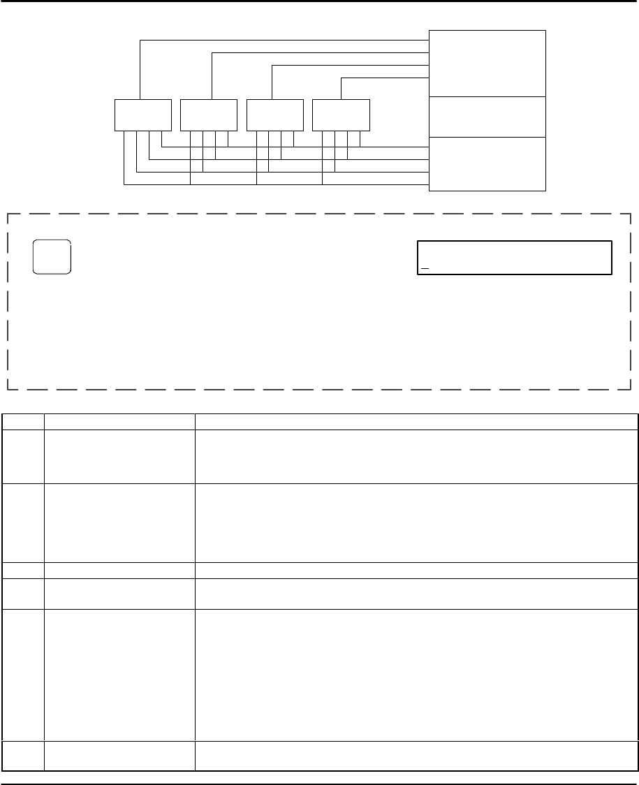
5-10 Setup MN1854
Figure 5-1
4
3
2
1
Data Valid
Unit
Selection
PLC
Program
Selection
LinStep
#1
LinStep
#2
LinStep
#3
LinStep
#4
Configuring Output Definition [ ODaaaaaaaa ]
EDIT > SETUP > I/O > OUTPUTS
Value: PPPPPPPP
Range:
OUT1: PROGRAMMABLE
PPPPPPPP ←↑↓→
Each input is easily configured using the keypad as described in Table 5-2. The function of
each input channel is indicated by a letter at the bottom of the display.
Note: Use the ← and → keys to select an Input. Then use ↑↓ to select the definition for each
input (described in Table 5-2).
Note: Lower case Input Characters (b, d, h, k and m) appear on the Keypad but are not used.
Select value, press ENTER
Table 5-2
Char Keypad Display Input Character Description
AAMP FAULT Amplifier Fault – Output goes low on any amplifier fault. An amplifier fault may
be due to temperature, motor short–circuits, excessive following error,
over–voltage and excessive regeneration conditions.
Note: This is not an all–inclusive fault output. Use F–Fault for this.
B
bBRAKE 1
BRAKE 2 It is often advisable that applications using a ball screw type actuator with a
vertical load use a brake to prevent the load from falling in the event of a fault.
The Brake output is normally disengaged, which is actually an ON condition.
When a fault occurs, power to the brake is removed and the brake is engaged.
This is a “fail–safe” type of brake, controlled by an OPTO module, and it requires
a customer supplied, 120VAC power supply, or 24 VDC with B Motors.
COVER CURRENT Not Used.
D
dDIRECTION 1
DIRECTION 2 The output remains set until motion is commanded in the reverse direction.
F FAULT The fault output acts as an all–inclusive fail–safe output. Under normal
operation the output is low (ON) and goes high (OFF) when any type of fault
occurs. A fault can occur from any amplifier fault condition (A) as well as for
the following general faults:
S BMA (Board Monitor Alarm) time–out
S Error finding Home – both limits were hit.
The exact cause of the fault can be determined a number of ways:
S Shown on keypad display
S RS–232C using the SS, SD, and SA status commands (see Appendix A)
S Other outputs can be configured to show more specific fault states
H
hAT HOME 1
AT HOME 2 The output goes high as long as the axis is at home.

Setup 5-11MN1854
Table 5-2 Continued
Char Keypad Display Input Character Description
LLIMIT ERROR The output goes low if a limit switch is hit during a normal move, or if both
limits are hit during a Go Home move.
M
mMOVE DONE 1
MOVE DONE 2 The output goes high as soon as an axis move is started and goes low when
a move is completed.
P PROGRAMMABLE Unassigned outputs are set to Programmable and can be used with OT
commands.
S STALL The output goes low if the control detects a motor stall.
Optional Opto I/O LinStep+ Dual Axis also supports up to eight Opto I/O modules (optional).
Configuring Input Definition [ OPaaaaaaaa ]
EDIT > SETUP > I/O > INPUTS
Value: IIIIIIII
Range: I=Input, O=Output
OPTO9: INPUT
IIIIIIII ←↑↓→
Each input is easily configured using the keypad. The function of
each channel is indicated by a letter at the bottom of the display.
Note: Use the ← and → keys to select an Input. Then use ↑↓ to
select the definition for each input (input or output).
Select value, press ENTER
Note: Use the ← and → keys to select
an Input. Then use ↑↓ to select
the definition for each input.
Configure the Output States
Configuring OPTO States at Power–up [ OEa,iiiiiiii ]
EDIT > SETUP > I/O > OUTSTS > PWR–UP
Value: OFF
Range: ON or OFF
On PwrUp Output #1
←↑ OFF ↓→
Each output is easily configured using the keypad. Select if the output should power–up in the ON or
OFF state.
Note: Use the ← and → keys to select an Output (1–8). Then use ↑↓ to select the definition.
Select value, press ENTER
Configuring OPTO States during a Fault [ OEa,iiiiiiii ]
EDIT > SETUP > I/O > OUTSTS > FAULT
Value: NO CHANGE
Range: ON, OFF or NO CHANGE
On Fault Output #1
←↑ No Change ↓→
Each output is easily configured using the keypad. Select if the output should be ON or OFF state or NO
CHANGE when a fault occurs.
Note: Use the ← and → keys to select an Output (1–8). Then use ↑↓ to select the definition.
Select value, press ENTER

5-12 Setup MN1854
Configuring OPTO States for Stop/Kill [ OEa,iiiiiiii ]
EDIT > SETUP > I/O > OUTSTS > ST/K
Value: NO CHANGE
Range: ON, OFF or NO CHANGE
On ST/K Output #1
←↑ No Change ↓→
Each output is easily configured using the keypad. Select if the output should be ON or OFF state or NO
CHANGE when a stop or kill command is received.
Note: Use the ← and → keys to select an Output (1–8). Then use ↑↓ to select the definition.
Select value, press ENTER
Configure End of Travel Switch Polarity
Configuring Motor Type [ ET ]
EDIT > SETUP > I/O > LIMITS
Value: NORM CLOSED
Range: NORM OPEN or NORM CLOSED
– Axis One EOT POL –
←↑ NORM CLOSED ↓→
Allows selection of Normally Open or Normally Closed polarity of the
End of Travel switch (EOT). Use ↑↓ to select the definition.
Select value, press ENTER
Press ← or → to select next axis.
Configure JOG Parameters
The keypad provides a convenient way to jog the motor. The parameters that
control your jog operation are configured using the JOG SETUP menu:
Action Display Comments
Press F2 (JOG) for more sub
menu selections. –↑SETUP↓–
I/O JOG HOME
Select a sub–menu, press F1 (I/O), F2
(JOG), or F3 (HOME).
Press ↓key for more sub menu
selections. –↑JOG SETUP↓–
ACCEL LO–VEL HI–VEL
Select a sub–menu, press F1 (ACCEL),
F2 (LO–VEL), or F3 (HI–VEL).
–↑JOG SETUP↓–
ENABLE
Select a sub–menu, press F1
(ENABLE)
Configuring JOG Acceleration [ JAr ]
EDIT > SETUP > JOG > ACCEL
Value: 50.0 {Accel Units}
Range: 0.0–9,999,999.0
– Axis One JOG Accel –
←50.0 in/s2→
Sets the acceleration and deceleration used during a jog move. Use
the numeric keys to enter a value (units were selected in the SETUP
> MECH > ACCEL menu).
Select value, press ENTER
Press ← or → to select next axis.

Setup 5-13MN1854
Configuring JOG Low Velocity [ JLr ]
EDIT > SETUP > JOG > LO–VEL
Value: 2.0 {Velocity Units}
Range: 0.0–9,999,999.0
– Axis One JOG Lo–Vel –
←2.0 in/s →
Sets the low speed JOG velocity. Use the numeric keys to enter a
value (units were selected in the SETUP > MECH > VEL menu).
Select value, press ENTER
Press ← or → to select next axis.
Configuring JOG Low Velocity [ JHr ]
EDIT > SETUP > JOG > HI–VEL
Value: 5.0 {Velocity Units}
Range: 0.0–9,999,999.0
– Axis One JOG Hi–Vel –
←5.0 in/s →
Sets the high speed JOG velocity. Use the numeric keys to enter a
value (units were selected in the SETUP > MECH > VEL menu).
Select value, press ENTER
Press ← or → to select next axis.
Configuring JOG Enable [ JEi ]
EDIT > SETUP > JOG > ENABLE
Value: Enabled
Range: Disabled or Enabled
– Axis One JOG Enable –
←Enabled →
Enables or disables JOG features. When disabled, an error
message is displayed when the jog buttons are pressed. JOG is
often disabled after installation to prevent access.
Select value, press ENTER
Press ← or → to select next axis.
Configure HOME Parameters
The homing function combines the flexibility of a customized homing routine with
the ease of use of calling a “canned program”. (Also see the GH command).
Action Display Comments
Press F3 (HOME) for more sub
menu selections. –↑SETUP↓–
I/O JOG HOME
Select a sub–menu, press F1 (I/O), F2
(JOG), or F3 (HOME).
Press ↓key for more sub menu
selections. –↑HOME SETUP↓–
MODE EDGE SWITCH
Select a sub–menu, press F1 (MODE),
F2 (EDGE), or F3 (SWITCH).
Press ↓key for more sub menu
selections. –↑HOME SETUP↓–
OFFSET DIR
Select a sub–menu, press F1
(OFFSET) or F2 (DIR).

5-14 Setup MN1854
Configuring Homing Mode [ HMi ]
EDIT > SETUP > HOME > MODE
Value: Switch Only
Range: Switch Only
–Axis One Home Mode–
←↑ Switch Only ↓→
Sets how a Go Home (GH) command will execute. The control will
only search for the appropriate edge of a switch.
Only one selection available.
Press ← or → to select next axis.
Configuring Home Edge [ HEi ]
EDIT > SETUP > HOME > EDGE
Value: NEGATIVE
Range: NEGATIVE, POSITIVE
– Axis One Home Edge –
←NEGATIVE →
Sets the home switch active on the negative edge or positive edge
of the encoder index channel. Use the ← and → keys to select.
Select value, press ENTER
Press ← or → to select next axis.
Configuring Home Switch [ HSi ]
EDIT > SETUP > HOME > SWITCH
Value: Norm Open
Range: Norm Open or Norm Closed
–Axis One Home Switch–
←Norm Open →
Selects the type of switch used for the home input. Use the ← and
→ keys to select.
Select value, press ENTER
Press ← or → to select next axis.
Configuring Home Offset [ HOr ]
EDIT > SETUP > HOME > OFFSET
Value: 0.0 {Distance Units}
Range: 0.0–999,999,999.0
–Axis One Home Offset–
←0.0 in →
Sets the offset from home position for the “real” home position. After
a successful homing move, the home position (the factory set home
position is +0.0000) is set to the offset value. Use the numeric keys
to enter a value.
This allows multiple systems to have identical programs and only
change the home offset value for each machine.
Select value, press ENTER
Press ← or → to select next axis.

Setup 5-15MN1854
Configuring Home Direction [ HFi ]
EDIT > SETUP > HOME > DIR
Value: POSITIVE
Range: NEGATIVE, POSITIVE
–Axis One Final Dir–
←Positive →
Sets the direction for the Go Home (GH) move. This is the direction used to
search for the encoder index mark (Z channel) after the appropriate home
switch edge is found.
Select value, press ENTER
Configure Power–up Program
The Program Setup menu allows selection of (1) a program to be immediately run
when LinStep+ is powered–up and (2) scanning conditions for the BCD or binary
program select inputs.
Action Display Comments
Press F1 (PROG) key for more
sub menu selections. –↑SETUP↓–
PROG RS232 MISC
Select a sub–menu, press F1 (PROG),
F2 (RS232), or F3 (MISC).
Configuring Power–up Program [ PUi ]
EDIT > SETUP > PROG > PWR–UP
Value: 0
Range: 0–400
– Power Up Program –
PROGRAM:0
Sets the program to run at power–up. The selected program is
executed (run) when power is applied or after a reset. If a value of 0
is entered in this menu, or if the specified program does not exist, no
program is run. Use numeric keys to enter program number.
Select value, press ENTER
Configuring Scan Conditions [ SNaaaaaaaa ]
EDIT > SETUP > PROG > SCAN
Value: YYYYYYY
Range: YYYYYYY, NNNNNNN
– Stop After Scan –
←↑ YYYYYYY ESC ↓→
Selects the events that cause the control to stop scanning program–select
configured inputs. The selected event is listed to the right of these 7
characters: ESCape, STOP, LIMIT+, LIMIT–, KILL, FAULT or INTerrupt.
If a stop–scan event is enabled, the system will stop scanning the inputs for
program numbers when that condition occurs. To resume scanning, a reset
(Warm Boot input or cycle power Off then On) must be given. This option
has no effect if the inputs are not configured as program select inputs (either
BCD or Binary).
Select value, press ENTER

5-16 Setup MN1854
Configuring Scan Delay [ DYi ]
EDIT > SETUP > PROG > DELAY
Value: 100
Range: 0–99,999
– Scan Debounce –
DELAY (ms):100
Sets the amount of time required for the program select inputs (BCD or Binary) to
remain stable before they are valid. The minimum time is 2 ms. If program select
inputs are not stable for a time equal to or greater than the specified delay, the
program will not be executed. Use the numeric keys to enter a value in ms.
Note: See Data Valid Input Configuration for an alternate approach.
Select value, press ENTER
Configure Serial Communications
To use the LinStep+ serial port, several things must be done first. Use the keypad
to set the auto–echo and the unit’s daisy chain address. The baud rate and other
parameters have fixed values and may not be changed.
S Baud rate: 9600
S Data bits: 8
S Stop bits: 1
S Parity: none
Action Display Comments
–RS232C SETUP–
ECHO UNIT#
Select a sub–menu, press F1 (ECHO),
F2 (UNIT#).
Configuring Echo Enable [ ECi ]
EDIT > SETUP > RS232 > ECHO
Value: Enabled
Range: Enabled, Disabled
– RS232C ECHO –
↑ENABLED ↓
Enable or disable the RS–232C ECHO feature. If ECHO is disabled,
characters received by the control’s serial port will not be
re–transmitted. ECHO must be enabled in daisy–chain applications.
Select value, press ENTER
Configuring Unit Number [ UNi ]
EDIT > SETUP > RS232 > UNIT#
Value: 1
Range: 1–99
↑ Unit Number ↓
NUMBER:1
Set the unit’s address. Each unit in an RS–232C serial daisy chain
of multiple units must have a unique Unit Number.
Select value, press ENTER
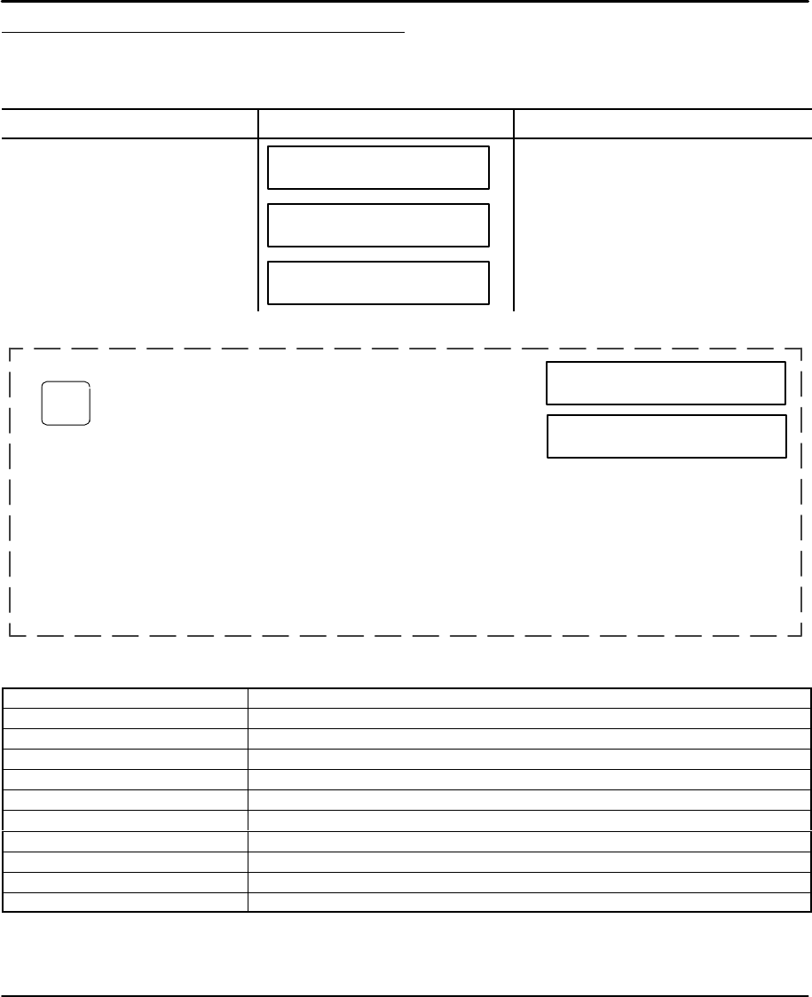
Setup 5-17MN1854
Configure Miscellaneous Setup Parameters
The miscellaneous set–up (MISC SETUP) parameters include the keypad display,
and setting the deceleration rate used with a stop input (or with the ESC key while
an axis is moving).
Action Display Comments
Press EDIT key –↑EDIT↓–
PROG SETUP POS
Select a sub–menu, press F1 (PROG),
F2 (SETUP), or F3 (POS).
Press F2 (SETUP) key for more
sub menu selections. –↑SETUP↓–
PROG RS232 MISC
Select a sub–menu, press F1 (PROG),
F2 (RS232), or F3 (MISC).
Press F1 (DISP) key for more sub
menu selections. ↑MISC SETUP↓
DISP Stop–Rate Test
Select a sub–menu, press F1 (DISP),
F2 (Stop–Rate), or F3 (Test).
Configuring Display Format [ DF ]
EDIT > SETUP > MISC > DISP
Value: 1=POS1, 2=POS2, 3=Inputs, 4=Outputs
Range: See Table 5-3.
←↑ QUAD#1 DISPLAY ↓→
↑POS1 ↓
The “Run Time” screen of the data display can be customized. The
run time screen has four 10 character segments called quadrants.
Each quadrant can display one of the data types defined in Table 5-3.
Select one quadrant, then assign a data type to that quadrant, press
ESC to save the data type. Repeat this process for each quadrant.
Note: To define the text for the “text” data type, scroll to the text data
type selection and press the “ALPHA” or a number key. A
cursor is then displayed, enter up to 10 characters then press
ENTER followed by the ESC key to save and exit.
Use the ←↑↓→keys to select a
Quadrant (1–4), press ENTER.
Use the ↑ and ↓ keys to select a
data type.
<QUAD#1> QUAD#2
QUAD#3 QUAD#4
Table 5-3
Data Type Description of Display Data Type
Blank No Display
POS1 (POS2) Axis Position (axis 1 or 2)
POS1+Unit (POS2+Unit) Axis Position with axis units (axis 1 or 2)
VEL1 (VEL2) Commanded Axis Velocity (axis 1 or 2)
Inputs Discrete input status (0=Off, 1=On)
Outputs Discrete output status (0=Off, 1=On)
OPTOS Opto I/O status (0=off, 1=on) as configured)
SA_Status1 (SA_Status2) SA (Tell Axis Status) serial command response (axis 1 or 2)
SS_Status SS (Tell System Status) serial command response
Text User defined text

5-18 Setup MN1854
Configuring Stop Decel Rate [ SRi ]
EDIT > SETUP > MISC > Stop–Rate
Value: 80 in/s2
Range: 0.0–99999.0
– Axis One Stop Decel –
←80 in/s2→
Set the deceleration rate used whenever a configurable stop input is
activated, or when the ESC key is pressed during a move. Normally
set to the fastest controllable deceleration rate possible with
mechanics in your application.
Enter a value, press ENTER
Configuring Passwords [ PWaaaa,aaaa ]
EDIT > SETUP > MISC > PASWRD
Value: None
Range: N/A
– Password Setup –
OPRATR ADMIN CLEAR
Passwords allow you to restrict access to the RUN, EDIT, COPY, DEL
and keypad DIP switches. Select Operator or Administrator (see
Table 5-4 for description).
Enter a password, use ←→ and DEL keys to edit the password.
General Password Rules:
S Passwords are 4 characters maximum. 0–9, upper and lower
case letters, in any combination.
S If no password is entered, there is no restriction.
S Entering the wrong password or pressing ESC at the password
prompt will return the keypad to the standard run–time display.
S Select EDIT > SETUP > MISC > PASWRD > CLEAR to delete all
passwords.
Note: Subsequent attempts to RUN or EDIT a program do not
require a password. You are prompted to: Use Last (F1) or
Reset (F3). Select Use Last to run or edit another program.
Select Reset to require the next user to enter a password.
Select a value, press ENTER
Table 5-4
Password Type Description Gives access to these menus
OPRATR Operator only RUN, EDIT, COPY, DEL
ADMIN Administrator only RUN, EDIT, COPY, DEL
CLEAR Clears Passwords

Section 6
Keypad Programming
Keypad Programming 6-1MN1854
Commands The programming commands that can be entered from the keypad are listed in
Table 6-1.
Table 6-1 Keypad Program Command List
AC Acceleration GH Start Home OT Outputs On/Off
CL Not Implemented FK Function Key MS Message to Display
CT Not Implemented GI Go Immediate ON On Condition
DA Distance Absolute GO Go (Start a Move) “__” “Message to Serial Port”
DC Distance to a Change GS Gosub RG Registration Move
DE Deceleration GT Go To Program SP Set Position
DI Distance Incremental IF If (conditional) ST Stop Move on Input
EB End of Block IV Input Variable TD Time Delay
EN End of Program LP Loop VE Velocity
MC Move Continuous WT Wait
Value: N/A
Units: seconds, in/sec2 or units/sec2 (set in EDIT > SETUP > MECH > ACCEL)
Range: Unit scaling dependent
Sets the acceleration and deceleration ramps on all velocity changes. The deceleration value (DE) is the
same as the acceleration value unless DE is specifically set after the AC command (the value of DE must
then be changed every time AC is changed). Change only AC if you want a symmetrical move profile.
Examples:
AC2 VE12 DA3 GO Sets acceleration and deceleration to 2.
DE.5 VE12 DA6 GO Accel stays at 2, decel changes to 0.5.
VE20 DA0 GO Acceleration and deceleration remain at 2 and 0.5.
AC4 DA2 GO Acceleration and deceleration become 4.
DE3 AC1 DI3 GO DE reset to 1 by AC1 before the move is made.
AC Acceleration syntax – ACr

6-2 Keypad Programming MN1854
Value:
Units:
Range:
CL Not Implemented syntax –
Value:
Units:
Range:
CT Not Implemented syntax –
Value: N/A
Units: set in EDIT > SETUP > MECH > DIST
Range: Unit scaling dependent
Sets the next move position, referenced from absolute zero. The absolute zero position is established after a
Go Home move (GH) and/or with the Set Position (SP) command. Absolute positioning is typically used to
move between a number of known locations, or if the physical work area is restricted.
Incremental (DI) and absolute moves may be mixed; the control keeps track of the absolute position.
Example:
AC2 DE.5 VE12 DA3 GO Moves to absolute position 3 units.
DA3 GO DA3 GO Moves once to absolute position 3 units.
DA Distance Absolute syntax – DA±r

Keypad Programming 6-3MN1854
Value: N/A
Units: set in EDIT > SETUP > MECH > DIST
Range: Unit scaling dependent
Defines complex, multiple velocity move profiles, or to change an Output at a specific point during the move.
It defines the distance at which a change will occur, “on the fly”, while the motor is still moving. At the
specified distance you can change the velocity, acceleration, deceleration or change the state of an
output(s). The DC command must follow the DA or DI command which specifies the total move distance.
The DC distance is interpreted as an absolute position when used with DA and an incremental position
when used with DI. When used with DI, the value of DC should be specified as a positive number. When
multiple DC’s are specified within an incremental move (DI), the incremental distance specified by the DC
command is taken from the last DC command, not from the beginning of the move. A maximum of 20 DC
commands within a move profile are supported.
Examples:
AC.05 DE.05 VE10 DA4 DC1 OT100 DC2 OT010 DC3 OT001 GO
While moving to an absolute position of 4 units turn on output 1 at 1 unit, output 2 at 2 units and output 3 at
3 units.
AC.05 DE.09 VE30 DA6 DC3 VE15 GO
Move to absolute position 6 units with a starting speed of 30. At 3 units, reduce speed to 15 (change–on–fly)
and complete move.
AC1 DE.5 VE20 DI–8 DC1 OT10 DC3 OT01 GO
Move an incremental distance of negative 8 units. After 1 unit turn on output 1 and after 3 MORE units of
motion, turn off output 1 and turn on output 2.
AC.05 DE.15 VE50 DI15 DC5 VE10 DC5 VE5 GO
At a starting speed of 50, begin moving an incremental distance of 15 units. After 5 units, ramp down to 10
speed. After 5 MORE distance units ramp down to 5 speed and continue until the final position is reached.
DC Distance to Change syntax – DC±r
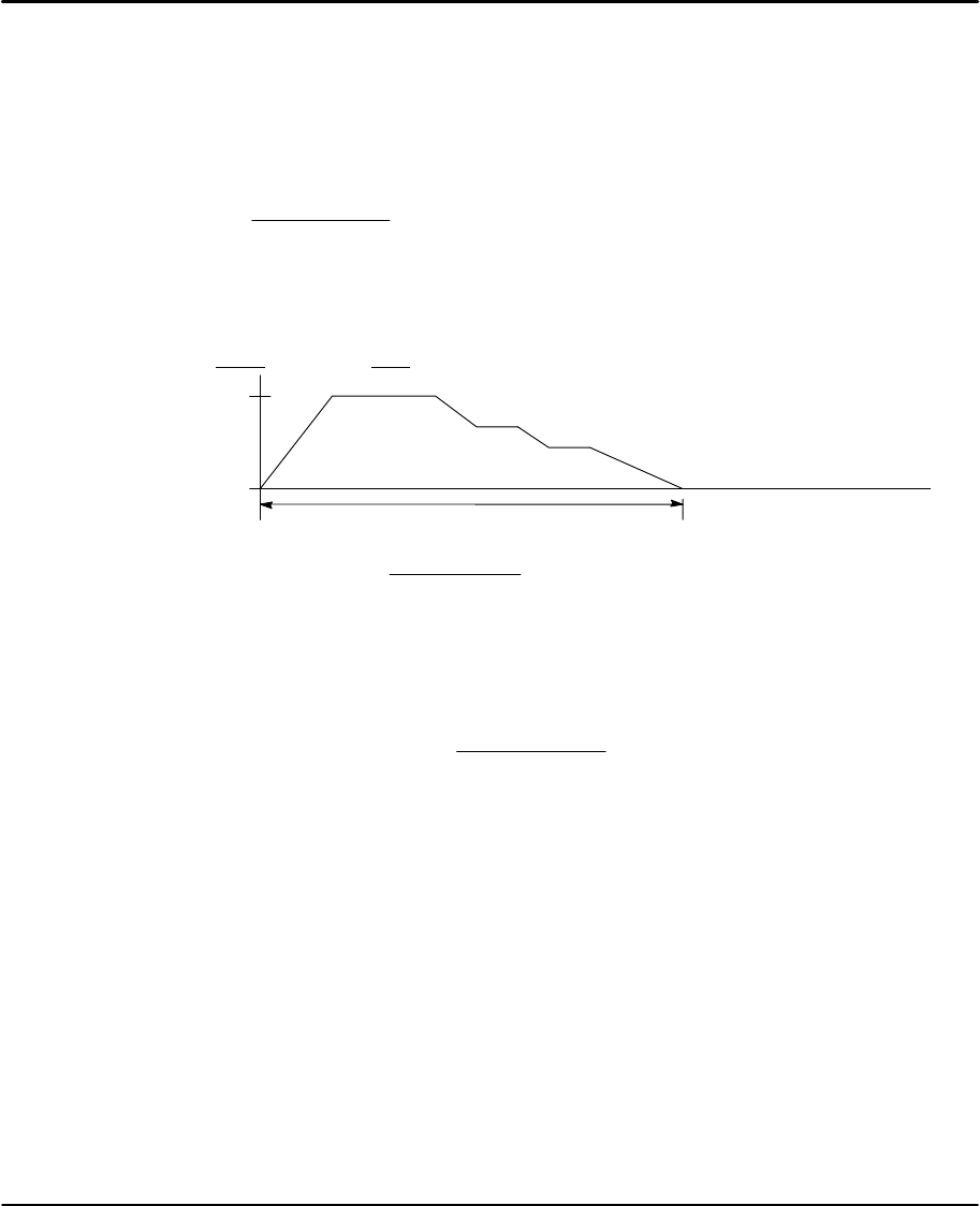
6-4 Keypad Programming MN1854
Example: (Distance to Change)
The DC command can only be used when the motor is moving at constant speed (no
acceleration of deceleration). Issuing a DC command before a previous DC command has
finished executing is invalid and can cause unpredictable results. (For example, “AC1 VE
DA20 DC1.75 VE7.5 GO” is incorrect use of the DC command). The initial acceleration
ramp requires 2.5 units to reach velocity S= 0.5Vt, the DC1.75 is an invalid trigger position
and is ignored. The following formula ensures the use of valid DC trigger positions:
DCn*DCn*1*(|Vn*1*Vn|)t
2w0
Where:
n is the commanded DC distance (n=19 in this example)
n–1 is the previous commanded DC distance (for example 10)
V is the velocity
t is the acceleration time
(The first commanded DC move in a profile, n–1 is the beginning
of the move).
Examples of DC move profiles:, AC = seconds, VE=ips.
AC1.6 DE0.8 VE5 DA20 DC10 AC2.5 VE3 DC? VE2.5 GO
510
?19
20 Units
To calculate DCn (or DC? in the example)
DCn+(|5*3|) (2.5)
2)10 +12.5
“?” must be ≥ 12.5 distance units. Also, the DC trigger position and the DC? VE2.5
segment must be verified or determined before the beginning of the move declaration. If “?”
is chosen to be 13.35 (a valid trigger position), use the beginning of the decel ramp as DCn
in the DC formula. A decel ramp from 2.5 to 0 requires 1 distance unit in 0.8 seconds (S=
0.5Vt).
19 *13.35 *(|0*2.5|) (0.8)
2+5.65
Since the result is positive, the DC13.35 VE2.5 is a valid segment.
AC.05 DE.05 VE10 DA4 DC1 OT100 DC2 OT010 DC3 OT001 GO
{While moving to an absolute position of 4 units, turn on output 1 at 1 unit, output 2
at 2 units and output 3 at 3 units}
AC.05 DE.09 VE30 DA6 DC3 VE15 GO
{Move to absolute position 6 units with a starting speed of 30. At 3 units, reduce
speed to 15 (change–on–fly) and complete move}
AC1 DE.5 VE20 DI–8 DC1 OT10 DC3 OT01 GO
{Move an incremental distance of negative 8 units. After 1 unit, turn on output 1,
and after 3 additional units of motion, turn off output 1 and turn on output 2}
AC.05 DE.15 VE50 DI15 DC5 VE10 DC5 VE5 GO
{At a starting speed of 50, begin moving an incremental distance of 15 units. After
5 units, ramp down to 10 speed. After an additional 5 distance units, ramp down to
5 speed and continue until the final position is reached}

Keypad Programming 6-5MN1854
Value: N/A
Units: seconds, in/sec2 or units/sec2 (set in EDIT > SETUP > MECH > ACCEL)
Range: Unit scaling dependent
Sets the deceleration ramp for all negative velocity changes. This value is the same as the acceleration
value unless a deceleration is specified. The value is used on subsequent moves unless it is re–specified by
an acceleration (AC) or deceleration (DE) command.
Examples:
AC2 VE12 DA3 GO Sets acceleration and deceleration to 2.
DE.5 VE12 DA6 GO Accel stays at 2 and decel changes to 0.5.
VE20 DA0 GO Acceleration and deceleration remain at 2 and 0.5.
AC4 DA2 GO Both acceleration and deceleration become 4.
DE3 AC1 DI3 GO AC1 sets both the accel and decel to 1.
DE Deceleration syntax – DE±r
Value: N/A
Units: set in EDIT > SETUP > MECH > DIST
Range: Unit scaling dependent
Specifies a move distance relative to the current position. Such moves are called incremental moves, as
opposed to the absolute move (DA). Use incremental moves when there is no concern for origin, such as
feed–to–length applications. DI is also often used inside a loop to shorten a program. Incremental and
absolute moves may be mixed; the control keeps track of the absolute position.
Example:
AC.1 VE60 DI2 GO DI1 GO DI–4 GO
Move 2 units in the + direction. Move 1 more unit in the positive direction. Move 4 units in the negative
direction. The final absolute position is –1.0000.
DI Distance Incremental syntax – DI±r

6-6 Keypad Programming MN1854
Value: N/A
Units: N/A
Range: N/A
The EB command designates the End of a Block of loop or IF commands. Every LP, LW, LU, and IF
statement must have an EB associated with it.
Examples:
LP2 DI3 GO EB Performs the move twice
IF1,1 DI5 GO DI10 GO EB GH3 If input 1 is On, make 2 moves before homing. If input 1 is Off,
jump to the GH command.
EB End of Block syntax – EB
Value: N/A
Units: N/A
Range: N/A
EN marks the end of a program or subroutine. It is optional at the end of a program. If EN marks the end of
a subroutine, command execution continues from the command following the gosub (GS) command that
called the subroutine. If the routine was not called from another program, the EN command simply stops
execution. The control continues to monitor the program select inputs (if defined). The EN command can be
used anywhere in a program to stop command execution.
Example:
IF2,1 EN EB DI2 GO If input #2 is on, stop the program, or return to the calling program. If not,
move 2 units.
EN End of Program syntax – EN

Keypad Programming 6-7MN1854
Value: N/A
Units: N/A
Range: i=1–28
The FK command allows you to define a function key within your program. The FK command pauses
processing until the buttons you have “armed” are pressed. The number of the button pressed is assigned to
the system variable, (FKEY). You can then manipulate or directly use this variable to branch to other
routines or make other decisions. FK allows the programmer to redefine the keypad’s function keys as
operator menu selection buttons. You can even write your program with menus that look and feel like our
setup menus. The returned values of the FKEY’s are:
Note: 24, the ESC key, cannot be assigned since it stops the program.
FK Function Key syntax – FKi,i,..,i
Example:
FK1,2,3,4
GS(FKEY)
Pauses command execution until F1, F2, F3, or RUN is pressed on the keypad. (FKEY) is assigned a value
of 1–4. Subroutine 1–4 is called with the GS(gosub) command.
Figure 6-1 shows how to use the keypad function keys as an operator interface. A 3–screen menu program
is provided
1. Write a menu message (MS) on the keypad display above the corresponding function keys.
2. Use the FK command to pause command processing until the operator selects a valid function key. Only
keys explicitly defined in the FK statement are considered valid.
3. Gosub to the appropriate program.
F1
=1F2
=2F3
=3
RUN
=4EDIT
=5HELP
=6COPY
=7DEL
=8
1=92=10 3=11
4=14 5=15 6=16
7=19 8=20 9=21
ESC
0=25
±ALPHA ENTER
,
.
u
↓
→
↑
=12 =13
=17 =18
=22 =23
=27 =28=26
=Not
Used

6-8 Keypad Programming MN1854
Figure 6-1 Example 3–Screen Menu Program
Program 20:
[SCREEN 1] Name the main program
MS1,“ “ Clears keypad screen
MS3,“Select a Part” Writes a Message
MS21,”Part A Part B Part C”Writes a message above function keys
FK1,2,3,17,18 Wait for selected key press
GT(FKEY) Jumps to prog# 1, #2, or #3 if F1,F2, or F3 is pressed Jumps to prog #17, or
#18 if the up or down arrow keys are pressed.
EN End of Routine
Program 18:
[SCREEN 2]
MS21,“Part D Part E Part F” Writes a message above F1, F2, F3.
FK1,2,3,17,18 Wait for selected key press
IF(FKEY)=17 GT[SCREEN 1] EB If Up arrow goto screen 1
IF(FKEY)=18 GT[SCREEN 3] EB If Down arrow goto screen 3 (FKEY)=(FKEY)+3 Add offset to FKEY variable to goto
correct part subroutine.
GT(FKEY) Jumps to part D, E, F in program#4, 5, or 6
EN End of Routine
Program 17:
[SCREEN 3]
MS21,“Part G Part H Part J” Writes a message above function keys.
FK1,2,3,17,18 Wait for selected key press
IF(FKEY)=17 GT[SCREEN 2] EB If Up arrow goto screen 2
IF(FKEY)=18 GT[SCREEN 1] EB If Down arrow goto screen 1
(FKEY)=(FKEY)+6 Add offset to FKEY variable to goto correct part subroutine
GT(FKEY) Jumps to part G, H, J in program #7,8 or 9
EN End of Routine
The programs to make Parts A, B, C, D, etc. are in program numbers 1–9. To continuously cycle through put a
GT[SCREEN 1] at the end of each part program.

Keypad Programming 6-9MN1854
Value: N/A
Units: set in EDIT > SETUP > MECH > ACCEL > VEL
Range: Unit scaling dependent
Initiates a homing routine (seeks the home switch) to establish a home reference position. When it reaches
home, the position counter is set to zero or to the Home Offset (HO) value selected in the EDIT > SETUP > HOME
menu. The motor will move at the GH velocity (n) and direction (±) specified until it either finds a home limit switch
or determines that it can not find one between the two end–of–travel limit switches. The Go Home move uses
the last acceleration and deceleration specified.
The exact homing routine used, and the ultimate end position of your system’s home reference, depends on the
values of your EDIT > SETUP > HOME parameters (edge, level, final approach direction, and offset) and if you
have specified open or closed loop moves in the EDIT > SETUP > ENCODER menu. The control will reverse
direction when the first End of Travel limit switch is encountered while searching for a Home switch. If the second
End of Travel switch is encountered, the unit will abort the Go Home move and generate a fault. Assuming the
presence of an operational home switch, the control will seek a home position according to the parameters you
specified (edge, level, final approach direction, and offset).
Closed loop systems will normally home with more accuracy than open loop systems because encoders have
a Z marker pulse. In a typical Go Home routine, the control will first sense the edge of the switch defined in the
Go Home SETUP menu. It will then decelerate the motor to a stop at the last defined deceleration rate. The final
homing motion is determined by the Go Home options selected in the SETUP menu. The final homing direction
dictates the direction from which the final approach to the switch is made. The edge selected will determine
which side of the home switch this final approach will be based from.
In a “closed loop” mode Go Home routine, the control will additionally slow to a creep speed and stop when it
sees the encoder’s “Z” Marker Pulse after seeing the reference edge of the switch. If a marker pulse is not seen
within one motor revolution after the reference edge of the switch is seen, the final homing routine will be aborted.
Note: Homing Mode directly affects or reconfigures the function of the GH command.
Examples:
AC.5 DE.5 GH–20 Go Home in the negative direction at a speed of 20
AC.5 DE.5 GH20 Axis one Go Home in the positive direction at a speed of 20.
GH Start Home syntax – GH±r
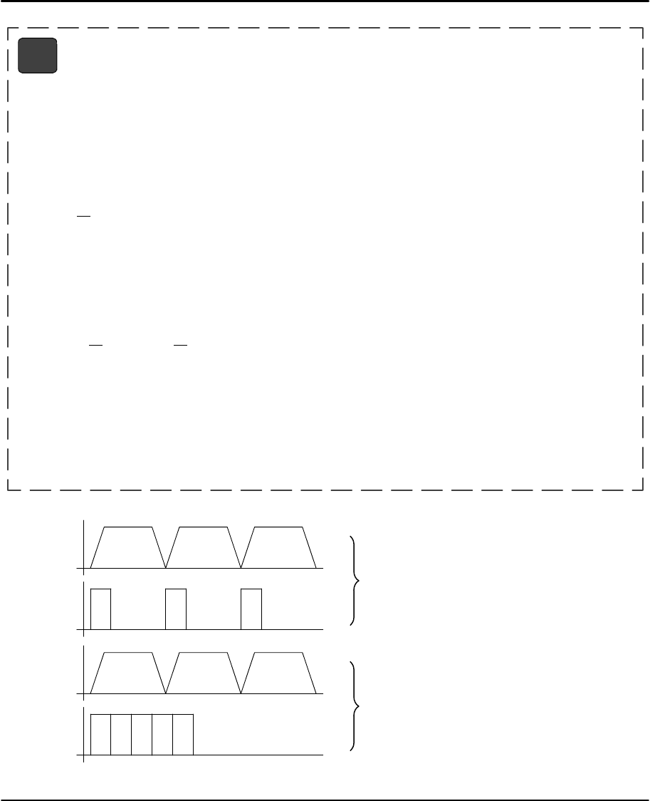
6-10 Keypad Programming MN1854
Value: N/A
Units: N/A
Range: N/A
The GI command begins a defined move profile in the same manner as the GO command. Unlike the GO
command, where program execution waits until all defined moves have terminated, GI allows program
execution to continue when the move has begun. This allows for other program defined processes to take
place while an axis is moving, such as independent multi–axis moves, OT commands, and conditional IF
blocks.
Examples:
VE1 DI20 GI MS1, “Axis #1 is moving” TD2
In this example, when the DI20 move begins, program execution immediately displays the “Axis #1 is
moving” message for 2 seconds. When the TD2 command has executed, the program will terminate;
however, axis #1 will continue to move until the DI20 distance is reached. A Stop, Kill, or press of the
ESC key will halt a GI based move either inside or outside program execution.
The GI command can cause program execution and moves to be asynchronous. To re–synchronize the
end of a GI move with program execution, use the Wait (WT) command, i.e. WT#1 will wait for only axis
#1. If a program error occurs during a GI move, the move will stop at the Stop Decel Rate.
VE1 DA100 GI OT1,1 DA0 GI IF1,1 MS1, “All moves done” EB
If a GI move is in progress and an additional move is commanded on the same axis, the additional move
will not begin until the GI move has completed.
In this program, one may expect to see the message “All moves done” immediately after the DA100
move begins. In reality, the program will wait at the DA0 GI until the DA100 move has completed before
continuing. More simply stated, a move cannot be commanded to begin on an axis that is already
moving.
Since GI allows program execution to continue, there can be programming issues when using GI. For
example, in the program fragment “LP VE2 DI10 GI OT1 TD1 OT0 EB” shown in Figure 6-2, after the
first pass through, the loop command (LP) will wait at the GI command since subsequent GI moves must
wait for the present move to finish.
GI Go Immediate syntax – GI or GIi
Figure 6-2
V
T
V
T
Axis 1
Output 1
1 Second 1 Second The program will operate as shown here.
V
T
V
T
Axis 1
Output 1
The program will not operate as shown here.

Keypad Programming 6-11MN1854
Value: N/A
Units: N/A
Range: i=1–16
GO executes a move profile defined by some combination of AC, VE, DE, DI, DA, DC, or MC commands.
Actual motion of a new profile will occur after a short calculation of the motion trajectory. GOn pre–calculates
the move and waits for Input number “n” to activate before executing. This variation is sometimes useful for
applications needing very short, repeatable move calculation delays. It is more often used simply to shorten
code, since it functions like the combination of Wait on Input and Go (WTn GO) yet it pre–calculates the
move. Like other commands using I/O, GOn does not restrict you from using an input even if it has been
configured for some predefined function.
Examples:
AC.05 DE.05 VE50 DI5 GO GO initiates calculation of a move profile using buffered parameters (.05 unit
Accel and Decel Ramp, speed 50, 5 unit incremental move) and executes it.
AC.05 DE.05 VE50 DI5 GO2 When input 2 is activated, immediate execution of the motion calculation
already in the buffer is performed.
GO Go (Start a Move) syntax – GO or GOi
Value: N/A
Units: N/A
Range: N/A
GP Go Point(Start a Move) syntax – GP or GPn
The GP command allows a LinStep+ two axis to execute a linear interpolated move. An example of the GP
move is shown. The path velocity, acceleration and deceleration are specified by the parameters
traditionally defined for one axis move. These parameters are defined once and each GP move there after
will use these values until new values are entered. The end point of the move is specified by a two axis DA
or DI command to the appropriate X and Y coordinates.
In the example, the path velocity is 2 user units/sec, path acceleration is .1 sec and the X,Y position is (4,2).
The GPn command specifies a discrete input must be active before executing the move. Although both
axes move during a GP move, all GP parameters refer to the path movement rather than the individual axis
movements.
Notes:
GP will work with any velocity or acceleration unit.
The largest GP move is restricted to X2+Y2 <= (231–1)2 in units of steps.
For example, the longest simultaneous X,Y point move is:
Steps: DA1518500249,1518500249
If resolution is 8000: DA189 812.5311,189 812.5311
If resolution is 25000: DA60 740.0099,60 740.0099
Commanding moves larger than X2+Y2 <= (231–1)2 will produce unpredictable results.
The DC command does not recognize an interpolated move as a ’single’ move and will treat the axes
independently. Therefore, using a DC during a GP move will cause unpredictable results unless the user
has calculated the necessary values to preserve the vector move.
(4,2)
X
Y
Example:
VE2 AC.1 DA4,2 GP

6-12 Keypad Programming MN1854
Value: N/A
Units: N/A
Range: i=1–400, [name] = any legal program name
Jumps to program number or name and returns to the calling program when command processing reaches
the EN command in the sub–routine. After the return, execution continues at the command immediately
following the GS statement. Subroutines may be nested 16 levels deep. A Goto (GT) clears the subroutine
stack, preventing future Gosubs from overflowing the stack or returning to the wrong location.
Example:
DI10 GS[Part A] GO Run program “Part A”, return and make a 10 unit incremental move.
GS Gosub syntax – GSi and GS[name]
Value: N/A
Units: N/A
Range: i=1–199 (1–400 with 30k memory option), [name] = any legal program name
GT branches to the program number or name specified. All subsequent commands in the calling program
are ignored. Nested loops and subroutine calls are cleared by a GT command.
Examples:
IF10 GT[PART A] EB IF input 1 is on and input 2 is off, jump to program “Part A”
IF01 GT20 GT30 EB EN IF input 1 is off and input 2 is on, run program 20. Program 30 is never run.
Use the GS command if you want to return to this program and goto
program 30.
GT Go to Program syntax – GTi or GT[name]

Keypad Programming 6-13MN1854
Value: N/A
Units: N/A
Range: i=starting input number 1–8
x=0; input high. X=1; input low (grounded). x=anything else; ignore input changes.
expression = any valid expression (see math and variables definitions)
Allows the conditional execution of a block of commands based on the evaluation of an expression or input
state. If the expression or input state is TRUE, the commands between the IF and the EB are executed. If
FALSE, execution continues with the command following the EB. An IF statement should not be confused
with a WT statement. An IF statement evaluates, true or false, based on the conditions at the instant the
command is processed. A WT statement pauses command processing until the condition is true.
Note: An End of Block (EB) command must be used with every IF command.
IF blocks can be nested up to 16 levels deep. To increase flexibility (primarily with programmable logic
controllers) the IF command allows you to use configured inputs with the command. To help prevent this
added flexibility from causing programming confusion, you can specify any character as an input (x). This
allows you to self document your IF statements. For example, assume you configure input #3 as a “JOG
SPEED” input. Programming like “IF01J10” can help remind you that you are already using input #3 as
“JOG SPEED”.
Examples:
IF14,1 GO EB If input 14 equals 1 Go
IF12,010 GO EB If inputs 12–14 equal 010 Go
IF110 GO OT3,1 EB If inputs 1–3 equal 110 Go and turn on Output #3
IF(TEMP) > 50 OT1 EB If temperature variable > 50 turn on Output 1
IF(PARTS)=25 GS20 EB If PARTS variable = 25 Gosub to Program 20
IF If syntax – IF (Mathematical expression)
IFxx (assumes first input is input 1)
IFi,xx ...

6-14 Keypad Programming MN1854
Value: N/A
Units: N/A
Range: i=1–40 display position characters
variable= any legal variable name
min=the minimum range value (optional); max=the maximum range value (optional)
Allows operator input of variable information under program control. It is usually used with the message
command (MS) to prompt for operator input of the variable specified in the IV statement. The cursor is
placed at character position “i”. The program waits until a number is entered before continuing execution.
You are not allowed to type past the end of either display line. Variables store 4 digits to the right of the
decimal place.
When minimum and/or maximum range values are specified, the IV command will not accept inputs outside
this range (one of the following messages is displayed on the keypad):
S Input below minimum, Press ESC to resume
S Input above maximum, Press ESC to resume
Variables can be used in a math equation, conditional expression or to set any command parameters
(Example: DA, DC, VE, AC, LP, IF, TD, etc.). A variable can be used anywhere in a program a real number
or integer is used. Use care when performing math on variables used in LP statements. LP will truncate the
non–integer portion of the variable. For example: (COUNT)=25*.2 LP(COUNT) will only loop 4 times
because (COUNT)=4.9999. A small offset can be added to variables used in LP statements to avoid this
problem. (COUNT)=(COUNT)+.1 will guarantee that (COUNT) will be greater than 5, so the program will
loop 5 times.
Examples:
MS1,“” Clears the Display
MS1,“How many?: ” Writes string beginning at character 1, top line
IV12,(PIECES),1,15 Waits at 12th character for the # of pieces in the range 1–15.
MS1,“” Clears the Display
MS1,“How long?: ” Writes string beginning at character 1, top line
IV12,(LENGTH) Waits at 12th character for the # of pieces.
LP(PIECES) Loops the number of pieces entered
DI(LENGTH) Defines the desired move length/distance.
GO Moves the length commanded
EB Ends the loop.
IV Input Variable syntax – IVi,(variable),min,max

Keypad Programming 6-15MN1854
Value: 0
Units: N/A
Range: N/A
Causes all commands between LP and EB to be repeated “i” times. If LP is entered without a number
following it or a 0, the loop will repeat continuously.
Note: An End of Block (EB) command must be used with every LP command.
Up to 16 nested loops (one inside the other) are allowed. Each LP command must have a corresponding EB
command to end the block (loop). A GT command within a loop will terminate the loop, clear the loop stack
and jump to a new program.
Example:
AC.09 DE.09 LP3 VE30 DI1 GO EB VE7 DI–3 GO EN
The motor will perform an incremental 1 unit move at speed 30 three times and then a 3 unit move at speed
7 in the other direction.
LP Loop syntax – LPi

6-16 Keypad Programming MN1854
Value: N/A
Units: N/A
Range: N/A
Sets move profiles to “continuous move”, using the AC, DE and VE parameters. Move Continuous is
enabled on an axis with the “+” sign. “MC+” enables the mode for axis one. DI, DA and DC commands reset
the mode to distance.
Each MC+ segment must contain a GO command. Accelerations, Velocities, and Decelerations may be
changed in any segment. If no change is specified, the last parameter value will be used. It is not valid to
issue positional commands (DI, DA, DC, GH, SP) to an axis while it is moving in continuous mode. Any
command is valid within an MC segment except Distance Commands (DA, DC, & DI).
The direction of the move is specified by the sign of the VE parameter. If the sign of the VE parameter
changes between two segments, the control will automatically stop the motor (at the programmed
deceleration rate) and change directions to the new speed. This makes changing directions based on
variable inputs very easy to program using a scaled variable as the VE parameter.
When a MC+ segment is started, it will continue to move at the speed specified by VE until another VE is
commanded, the ESC Key is pressed, or an End Of Travel, Kill Motion, Interrupt, or Stop Input is activated.
A commanded velocity of zero (VE0) stops a Mode Continuous move. Motion will also stop if the edit, help,
copy, or delete menus are opened.
After a continuous move segment has started, command processing will continue when constant velocity is
reached. Other commands are then processed sequentially. This allows you to do things like:
SHave asynchronous inputs change the speed of an axis
SMake motion profile changes based on time delays or input states
SManipulate I/O while moving as a function or time, distance, or input states
SChange speed based on analog inputs or variables
SHave an operator update the speed of an axis through the keypad
SServo to an analog input
SMake a one axis joystick using analog inputs
If a motor is making a move when it comes to the end of a program, the motor will continue moving, even
after the program ends. This allows you to:
SPut different MC moves in different programs and select different speeds by running different programs.
SChange speeds based on Binary or BCD program select lines
SCall MC+ moves as subroutines
SRun from “hosted” RS–232C mode, where the computer commands speed changes
SRun another program from the keypad that does not violate MC syntax. So you could run another
program from the keypad to change speeds, manipulate I/O, interface with an operator or calculate
arithmetic.
MC Move Continuous syntax – MC+

Keypad Programming 6-17MN1854
Move Continuous Continued
Examples:
1. Basic Move Continuous syntax. Demonstrates how to change speed and stop MC+ moves based on
time delays and input conditions.
MC+ Enable Move Continuous on axis 1
AC.1 DE.2 Set the acceleration and deceleration rates
VE50 Set top speed to 50
GO Start the Move Continuous move, command processing will continue when axis 1
reaches constant velocity
TD2 Delay for 2 seconds at speed
VE25 GO Decel to 25
WT111 Wait for inputs 1,2, and 3 to go active
VE0 GO Stop the move
2. Demonstrates how to prompt an operator for speed changes on a one axis LinStep+. The move is
started after the initial velocity prompt. The velocity only changes when the operator enters a new value
using the keypad. The move can be stopped by entering a velocity of zero, or when any of the stop
conditions defined above exist.
[One Axis MC]
MS1,“Enter the Velocity” Prompt the operator
IV23,(V) Put the operator input in variable (V)
MC+ AC1
VE(V) Use operator inputted variable (V) as new speed
GO Change velocity of axis 1 to the new speed
GT[One Axis MC] Repeat
3. Demonstrates the use of WT, OT and TD commands in continuous move.
MC+ AC3 VE3 GO Start first segment
WT8,1 AC.1 VE10 GO Wait for input 8 and change speed
TD5 AC.3 VE.2 GO Wait for 5 seconds and change speed
WT3,1 VE–10 GO Wait for input 3 and change speed and direction
OT11 Turn on outputs 1 and 2
TD10 VE0 GO Wait 10 seconds and stop the move

6-18 Keypad Programming MN1854
Value: N/A
Units: N/A
Range: n=1–40 characters
(20 on each line)
MS allows messages to be displayed on the keypad’s display. Messages are usually to prompt for operator
input, display function key prompts, or as a diagnostic tool.
MS,“” can be used to restore the initial axis position and I/O display during program execution. MSn,“” clears
the display from the n th character to the end of message. MSn,“user text” prints user text beginning at the n
th character. MSn,(variable) writes the value of the variable beginning at the n th character. These variations
to MS all disable the initial position and I/O display until program execution stops. MS,“” can be used to
restore the initial axis position and I/O display during program execution.
Examples:
MS1,“” Clears the Display.
MS3,“Part Count” Writes string beginning at character 3, top line.
MS27,(COUNT) Displays the value of the variable (COUNT), beginning at position number
27 (7th character, 2nd row).
This keypad programming template shows the relationship of the each character position to the location of
the function keys. This will help you align messages on the display. A larger version is located in the back
of this manual and can be photo copied for programming use.
MS Message to Display syntax – MS,“” returns to the initial runtime display
MSn,“”
MSn,“user text”
MSn,(variable)
M
1
S
2
2
3
7
4
,
5
(
6
C
7
O
8
U
9
N
10
T
11
)
12 13 14 15 16 17 18 19 20
21 22 23 24 25 26 27 28 29 30 31 32 33 34 35 36 37 38 39 40
Display
Lines
FK1 FK2 FK3

Keypad Programming 6-19MN1854
Value: N/A
Units: N/A
Range: N/A
Allows conditional program execution based on an event. When the programmable event occurs, the
current program and move are interrupted and program execution begins at the predefined interrupt
program. The interrupt program can be defined as a GT or a GS. Defining the interrupt as a GS allows
program execution to return to the exact point in the original program where the interrupt occurred. The ON
command currently supports End–of–Travel (EOT) as an event conditional.
After an ON event is defined, it is active in all user programs and need not be redefined except to change
the interrupt program type, number or name, or clear the event condition.
Example: Using ON to handle an EOT event.
[POWERUP]
ONL,GT[ON EOT] [Goto [ON EOT] {on an End–of–Travel input}
GT[HOME] {Home the machine}
[MAIN]
LP {Loop forever}
VE5 DA20 GO {Define move}
DA0 GO {Define move}
EB
[ON EOT]
IF(SA1)&256 {Check if EOT– switch was hit (bit #9 in SA)}
VEI DA0.5 GO {Move off EOT– switch}
GT[HOME] {Home the machine}
EB
VEI DA–0.5 GO {Move off EOT+ switch}
GT[HOME] {Home the machine}
[HOME]
GH3 {Home}
GT[MAIN] {Jump to main loop}
ON On Condition (On Event) syntax – ONn,GTx
ONn,GSx
ONn,0 Clear the event
n= On EOT Limit

6-20 Keypad Programming MN1854
Value: N/A
Units: N/A
Range: i=1 to 16
Sets both discrete and digital Opto output states. After an output is turned on (low), it remains on until
changed by another output command, a reset input (software warm–boot), or power is cycled. All outputs
are turned off (high) at power up or during a reset.
For flexibility, the OT command allows you to use configured outputs anytime. To help prevent programming
confusion, you can use any character in the “don’t change” section of your output statement. This allows you
to self–document your OT statements. For example, assume you configured output #3 as a “FAULT” output.
Programming like “OT01F10” can help remind you that you are already using output #3.
Example:
OT4,1 Turn on Output 4.
OT2,0D1 Turn Outputs 2 off, leave 3 as is, and turn 4 on.
OT110 Turn Outputs 1 and 2 on, and 3 off.
OT Output (turn outputs On/Off) syntax – OTi,xx ..
OTxx (assumes first input is input 1)
i= starting output number 1–16
x=0; input high. X=1; input low (grounded).
x=anything else; ignore input changes.
Value: N/A
Units: N/A
Range: N/A
The “” command transmits an ASCII string from the serial communications interface. A “” without any string
transmits a carriage return character (ASCII 13).
Example:
“Move Complete” Transmits string only out serial interface.
“” Transmits a carriage return only.
“” Quote syntax – Any ASCII Character
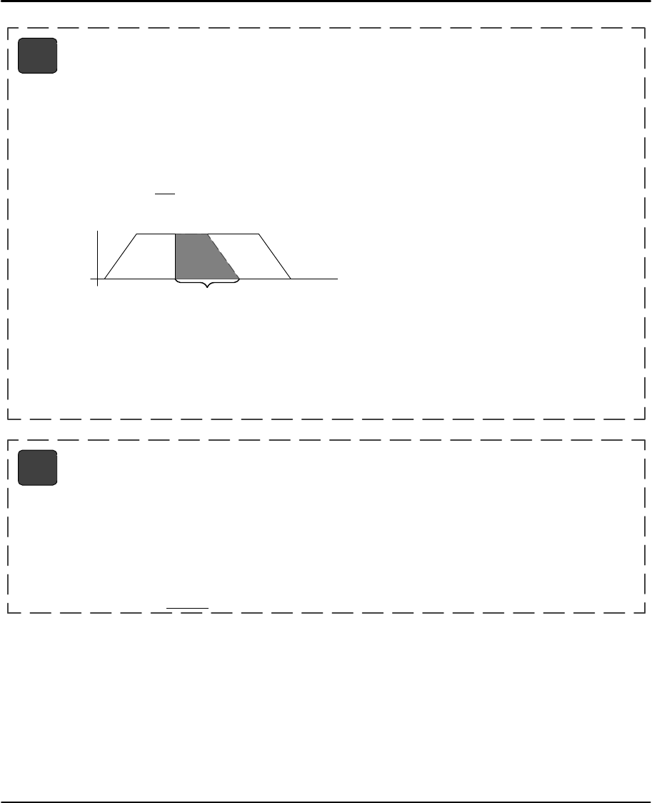
Keypad Programming 6-21MN1854
Value: N/A
Units: N/A
Range: N/A
The Registration command (RG) specifies a distance to be moved from the current position – as
commanded by a specific input trigger. For example, in the following program of 10 user–units on axis #1,
the input trigger is received at user–unit 4, to move 3 user–units from the point where the input trigger was
received.
VE2 AC.1 DA10 RG3 GO
Assume the input is an optical sensor that triggered on a registration mark at a position of 4 user–units. The
commanded move related to the registration move is as follows:
RG Registration syntax – RGr
V
T
Axis 1
4710
T=4 RG Input Trigger
T=7 RG End of Move
T=10 Ends at Commanded Position
RG
Index
Distanc
e
Accompanying the programmable Registration Command is the configurable Registration Input: G (also G in
Serial Setup Commands). To configure a Registration input from the keypad, choose EDIT > SETUP > I/O >
INPUTS. An input configured as a Registration Input is designated by a G on the keypad input status
display. The RG Command will only function if the corresponding input has been configured as a
Registration Input.
Note: Registration Input is only configurable on Input #1 for Axis #1.
Value: 0
Units: set in EDIT > SETUP > MECH > DIST
Range: varies with distance units
Sets the current absolute position to “n”. This command is typically used to adjust or shift a coordinate
system. It is often done after a series of incremental moves to reset the absolute coordinate frame.
Example:
MC+ GO WT1,1 VE0 GO SP10.5 After the move is complete, sets the current position of axis 1 to 10.5.
SP Set Position syntax – SP±r

6-22 Keypad Programming MN1854
Value: N/A
Units: N/A
Range: 0.0001 – 214748.3645
The SQ command calculates the square root of a number and returns the result in a user defined variable.
The n parameter in the syntax can be a number or a variable parameter, however, the second parameter
must be a previously defined variable for which the square root result is stored. If the second parameter is
not a defined variable, you will get a Bad Variable Name error. Following mathematical convention, SQ will
produce an Invalid Parameter error for negative “r” values. The return value is accurate to the 0.01 place.
Example: This program calculates the square root of 27.96 and stores the value in the user defined
variable (SQRESULT).
(SQRESULT)=0 SQ27.96,(SQRESULT) The returned value in (SQRESULT) is 5.28.
SQ Square Root syntax – SQr,(var)
Value: N/A
Units: N/A
Range: 0–8 inputs
ST stops move execution upon activating the input specified by n.
ST0 disables (turns off) the STn command.
ST#1 stops the move on axis #1. (Allows program command conditional program termination). ST#1,#2
stops moves on both axes. After ST is executed, the specified input is monitored during every “move
profile”. If the input is activated, the current “move in progress” is terminated, stopping all motion until the
input is deactivated or an ST0 is processed. LinStep+ will process and calculate commands, but will wait at
the next GO command until the ST input changes.
The motor is stopped at the deceleration rate specified in the Stop Decel Rate parameter. Once issued, Stop
on Input remains active until it is turned off by the ST0 command, a reset is issued, or power is cycled.
Example:
ST1 AC1 DE1 VE25 DA6 GO VE50 DA0 GO EN
Move to absolute position 6 units. If input 1 is activated while moving, Stop Motion. When the input is
deactivated, immediately execute the next move profile which is to move to the absolute zero position. If
input 1 is not activated while moving, the motor would complete its 6 unit move before executing the move
back to absolute zero.
ST Stop Move on Input syntax – STn (or ST#n)
STn,n (or ST#n,#n)
Value: N/A
Units: seconds
Range: r=0.01 – 99999.99
Delay r seconds before executing the next command.
Example:
VE50 DI4 GO OT11 TD.5 OT00
Move 4 units, turn outputs 1 and 2 on, delay .5 seconds, and turn outputs 1 and 2 off.
TD Time Delay syntax – TDr

Keypad Programming 6-23MN1854
Value:
Units: in/sec set in EDIT > SETUP > MECH > VEL
Range: varies with velocity units
Sets the maximum velocity during a move profile. If the acceleration rate is too slow or the move distance is
too short, the motor may make a triangular move (velocity vs. time) and the motor may never reach the
specified speed. When VE is specified, the value is used in all subsequent moves until re–defined.
Example:
AC.1 DE.2 VE50 DA4 GO Move to absolute position 4 units with a top speed of 50 in/sec.
VE Velocity syntax – VEr
Value: N/A
Units: N/A
Range: 1–16
Causes LinStep+ to wait for the specified condition to be true before continuing program execution. Either
digital or analog input conditions may be used. The WT command allows use of configured inputs in the
expression. To help prevent this from causing programming confusion, you can use any character as an
input (x). This allows you to self document WT statements. For example, assume input #3 is set to “JOG
SPEED”. Programming like “WT01J10” can help remind you that you are already using input # 3.
Example:
WT4,1 GO Wait for input 4 to equal 1 before moving.
WT2,010 GO Wait for inputs 2–4 to equal 010 before moving.
WT110 GO Wait for inputs 1–3 to equal 110 before moving.
WT#1 Causes program execution to halt (wait) until GI move is complete.
WT Wait syntax – WTi,xx...
WTxx... (assumes first input is input 1)
WTexpression
WT#1, (synchronized the program after a GI move)
i = starting input number, 1–16
x=0; input high. X=1; input low (grounded).
x=anything else; ignore input changes.
expression = any valid expression (see math and variables definitions)

6-24 Keypad Programming MN1854
Table 6-2 Summary of Expressions, Operators and Functions
[ ] Name Program
( ) Name Variable
&& Logical AND
|| Logical OR
!Logical NOT
!= Not Equal
+ Add
–Subtract
* Multiply
/ Divide
= Equal
>Greater Than
>= Greater Than or equal to
<Less Than
<= Less Than or equal to
&Bitwise Boolean AND
|Bitwise Boolean OR
++ Increment Variable
+= Increment by n
– –Decrement Variable
–=Decrement by n
<< Shift Left
>> Shift Right
Helpful Hints Programming your application
This section provides additional information that may be helpful to begin
programming the LinStep+. Also, several practical examples are given that can be
used or modified. More program examples are available on the Intelliware disk set.
Programming Overview
First, you must decide how the LinStep+ fits into the overall machine control
hierarchy. Generally there are three ways that the LinStep+ may be used:
1. Stand–alone mode – controls all the Inputs/Outputs and motion.
2. With a PLC – the PLC runs the machine and calls on the LinStep+ via
program select lines for motion.
3. In a “hosted” mode – the PC sends serial commands to the LinStep+ for
execution. The LinStep+ uses a sequential, interpretive command
processor. This means that commands in a program are executed one at
a time, and that one command must be completed before the next
command is processed.

Keypad Programming 6-25MN1854
[Move] VE4 DI10 OT01 GO OT10 Example of “Hosted” Mode
Program
In the program [Move], the maximum move velocity is set to 4, the command
incremental distance is set to 10, output 1 and output 2 are turned off and on
simultaneously, axis one then moves 10 units. After axis one stops moving, output
1 is turned on and output 2 is turned off. These changes of outputs 1 and 2 occur
at the same time.
The flow of the program is controlled with WT (wait for an event or condition to
occur), TD (wait for a pre–set amount of time to elapse), and IF (if a certain
condition is true at this instant, then execute a block of commands) statements.
External controllers such as PLC and computers can be coordinated by the digital
outputs and ASCII serial commands. The commands that can be entered from the
keypad and used in a program are listed in Table 6-1.
Variables Memory space allows for up to 100 variables. All variables are stored as fixed
point numbers. All variables are global. All standard variables are volatile, though
non–volatile variables are available as well. Variables can be used in many parts
of the program, such as:
SArithmetic
SConditional Expressions
SLoop Counts
SDistance and velocity commands
SSet values
SSet command values or parameters
SSet analog signals
SRead analog or temperature input
SDisplay information such as position or velocity
SAny place that a number can be used, a variable can be used
Variable Names
Descriptive variable names can be assigned, instead of V1, V2, etc. Variable
names can be up to 14 characters, but the first 10 characters must be unique. A
name can contain other printable ASCII characters, such as numbers,
underscores, exclamation points, even spaces. Upper and lower case characters
are supported within variable names, and these variable names are case
sensitive. ASCII control characters such as LF and CR are not supported. All
variables must be enclosed in parentheses, (variable name). Parentheses are not
legal variable characters.

6-26 Keypad Programming MN1854
Built–in Variables
Some variable names are pre–defined. They can be used in expressions, to set
voltages, to test conditions, or to display information to the keypad display or an
external serial device.
Variable Name Description of Built–in Variable Type
(AI1) to (AI6) Analog Inputs 1 through 6 Read Only
(AROWREL) Current status of any of the four arrow keys Read Only
(CPOS1) (CPOS2) Commanded position of axis 1 or 2 Read Only
(EPOS1) (EPOS2) Encoder position of axis 1 or 2 Read Only
(VEL1) (VEL2) Commanded velocity of axis 1 or 2 Read Only
(POS1) (POS2) Current Position of axis 1 or 2 Read Only
(#F1) thru (#F50) Non–volatile, limited use, user system variables Read/Limited Write
(FKEY) Value of Function Key pressed Read Only
(LASTKEY) Value of last Function key pressed Read Only
(TERM) Sends variable out RS–232 port Write Only
(1TW) Scans inputs 1–4 for BCD Digit Read Only
(2TW) Scans inputs 1–8 for BCD Digit Read Only
(TIME) Elapsed Time (ms) since power up or since reset Read Only
(CRCS) Value of the EEPROM setup checksum Read Only
(CRCP) Value of the EEPROM program checksum Read Only
(SA1) (SA2) Integer value of the status of axis 1 or 2 (SeeRS232 command SA) Read Only
(SD1) (SD2) Integer value of the drive status of axis 1 or 2 (See RS232 com-
mand SD) Read Only
(SS) Integer value of the system status (See RS232 command SS) Read Only
(INT98CTRL) Enables/disables (ARM INT98) trigger option Read and Write
(ARM INT98) Enables/disables INT98 input if (INT98CTRL) is enabled Read and Write
Examples of how to use Built–in Variables
(PIECES)=10 Assigns 10 to variable
(SPEED)=(AI12)*(VEL SCALE) Speed = analog input times a scalar
MS21,“Enter Length” IV32,(LENGTH) Prompts user and gets feed length
VE(SPEED) Sets velocity to value in variable
MS1,(POS2) Displays current position of axis 2 on keypad screen
(TERM)=(POS1) Sends the current position of axis 1 out the RS–232 port of the
Smart Drive
(TEMPERATURE)=(AI9) Reads in temperature from an analog input
(AO15)=4012 Sets the analog output to 4012
(#F1)=(PIECES) Stores the value of Pieces in FLASH memory variable #F1

Keypad Programming 6-27MN1854
Using Built–in Variable (AROWREL)
(AROWREL) is a built–in Boolean read only variable that determines the status of
any of the four arrow keys. When used with (FKEY), the program can detect if an
arrow key is being held down. (AROWREL) will only return the status of the four
arrow keys. If a different key is pressed, (AROWREL) will return the value 0.
(AROWREL) will return one of these values:
(AROWREL)=0 One of the arrow keys is being held down.
(AROWREL)=1 The arrow key has been released.
Example JOG application using (AROWREL) and (FKEY):
[MAIN] {Program #1}
FK12,13 {Wait for a Left or Right arrow key}
GT(FKEY) {Jump to arrow key program #12 or #13}
[LEFT ARROW] {Program #12}
MC+ {Enable MC mode}
AC.1 {Start MC move}
VE1 {Move in positive direction}
GO
LP
IF(AROWREL)=1 {Check status of arrow key}
VE0 {Stop MC move on key release}
GO
GT1 {Return to main program}
EB
EB
[RIGHT ARROW] {Program #13}
MC+ {Enable MC mode}
AC.1 {Start MC move}
VE–1 {Move in negative direction}
GO
LP
IF(AROWREL)=1 {Check status of arrow key}
VE0 {Stop MC move on key release}
GO
GT1 {Return to main program}
EB
EB

6-28 Keypad Programming MN1854
Non–Volatile Variables
(#F1) through (#F50) are fifty user variables stored in non–volatile flash memory
so they retain their values through power cycles, warm boots, and system resets.
Standard user variable are lost at power down or reset. When one of these
variables is changed (i.e. used on the left side of a equal (=) sign, the new value is
written to, and stored in the user non–volatile flash.
Note: Flash memory has a limited read/ write lifetime (100,000 writes before failure), variable values
that change frequently should not be stored as these variables. Examples include loop count
variables, and POS1 and POS 2 variables. LinStep+ will allow only 1,000 FLASH writes between
power cycles. This limit is set to prevent damage to non–volatile memory due to a simple
programming mistake or misunderstanding. When this write limit is exceeded, all programs will
stop running, an error message will be displayed, and the appropriate status bits will be set.
Example: At the start of each part run, a program called [Set–up] is used to
initialize a number of variable part parameters. During production the program
called [PARTS] is run. This program reads from the FLASH variables, but does not
generate any writes to the FLASH, so the lifetime of the FLASH is not
compromised.
[Set–up] {Program #1}
MS1,“Feed length?: ” Writes string beginning at character 1, top line
IV12,(LENGTH),1,15 Loads the part length to variable (LENGTH)
MS1,“Feed Speed?: ” Writes string beginning at character 1, top line
IV12,(SPEED),.05, 5 Loads the speed into volatile variable (SPEED)
(#F1)=(LENGTH) Loads the length into non–volatile variable (#F1)
(#F2)=(SPEED) Loads the speed into non–volatile variable (#F2)
EN
[PARTS] [PARTS] runs on power up, unless new parameters
are entered.
(LENGTH)=(#F1) Load part specific variable from non–volatile #F1.
(SPEED)=(#F2) Load part specific variable from non–volatile #F2.
LP(NUMBER) Loop (NUMBER) of times
DI(LENGTH) Move (LENGTH)
VE(SPEED) at (SPEED) velocity
GO
OT1 TD.1 OT0 Change output to indicate part done
EB End the loop Block

Keypad Programming 6-29MN1854
Arithmetic Operands and Equations
Addition (+), subtraction (–), multiplication (*), and division (/) are easily performed.
Expressions may only contain one operand. Complex equations require multiple
statements. Variables and fixed point numbers may be mixed in arithmetic
equations. All user arithmetic and variable storage uses 32 bit integer and
fractional representation. The + and – symbols have a dedicated button on the
keypad. Pressing the button will change between the two. The *, /, and = are
accessed with the Alpha+0+ ... keystrokes.
Example:
(X)=(Y)*10
(AO15=(VOLTAGE) + (ERROR)
Examples of incorrect use:
(X)=1+2–3 This statement is incorrect because it has more than
one operand.
(Length)=(Total)*0.3125 This statement is incorrect because it has more than
four decimal places.
Instead, you should use:
(X)=1
(X)=(X)+2 or (X)+=2
(X)=(X)–3 or (X)–=3
and
(Length)=(Total)*3.125 Multiply the significant figures
(Length)=(Length)*.01 Then move the decimal place
or
(Length)=(Total)/32 32 bit storage of fractional decimal number
Boolean Operators
Boolean operators & and | perform their respective bitwise Boolean functions on
immediate or variable parameters. As an example, isolate a specific bit from an
SD response to determine if axis #1 drive is enabled. This corresponds to a bit #5
(10000) Binary, (16) Integer in the SD response. The example program segment is
written as follows:
(DRIVE STAT)=(SD1)&16 IF(DRIVE STAT)=16 MS,1“Drive Enabled” EB
The 16 corresponds to an integer weight of bit #5 (10000).

6-30 Keypad Programming MN1854
Logical Operators
Conditional commands (IF,WT, LU, LW) support logical operations of AND (&&)
and OR (||). Two expressions may be logically AND’d or OR’d within one
conditional command. For example:
(A)=5 (B)=2.5 IF(A)>2&&(B)=2.5 MS1, “True Statement” EB
In this program, the message “True Statement” appears since BOTH conditional
statements are true.
Increment/Decrement Variables
Four syntaxes are supported by variables: ++ (Single Increment), += (Value
Increment), –– (Single Decrement), –= (Value Decrement). These operators will
initialize any uninitialized variable to zero before incrementing or decrementing it
for the first time.
(Variable Name)++ Increments a variable value by 1
(Variable Name)+=n Increments a variable value by n
(Variable Name)– – Decrements a variable value by 1
(Variable Name)–=n Decrements a variable value by n
Expressions
Five conditional expressions are supported: less than (<), equal to (=), greater
than (>), less than or equal to (<=), and greater than or equal to (>=). The IF and
WT commands can use these expressions to direct program flow or wait for an
analog input to meet a condition. The > and < symbols are entered into the keypad
editor with the ALPHA+↑+↑...↑
Examples:
IF (X)>10 GS20 EB If X is greater than 10 gosub to program #20.
WT(AI12)<(MAX TEMP) Wait for the temperature to go below the maximum
before continuing command processing.
Other Programming Samples
These sample programs provide an idea of how to solve simple programming
tasks. To aid your program documentation, comments are placed in {brackets}.
These comments are stripped from the program as it is downloaded for execution
to help conserve memory. Files should be saved before downloading save the
comments.
Example:
DI10,2 GO Moves to load position
DI15,15 GO Moves to unload position
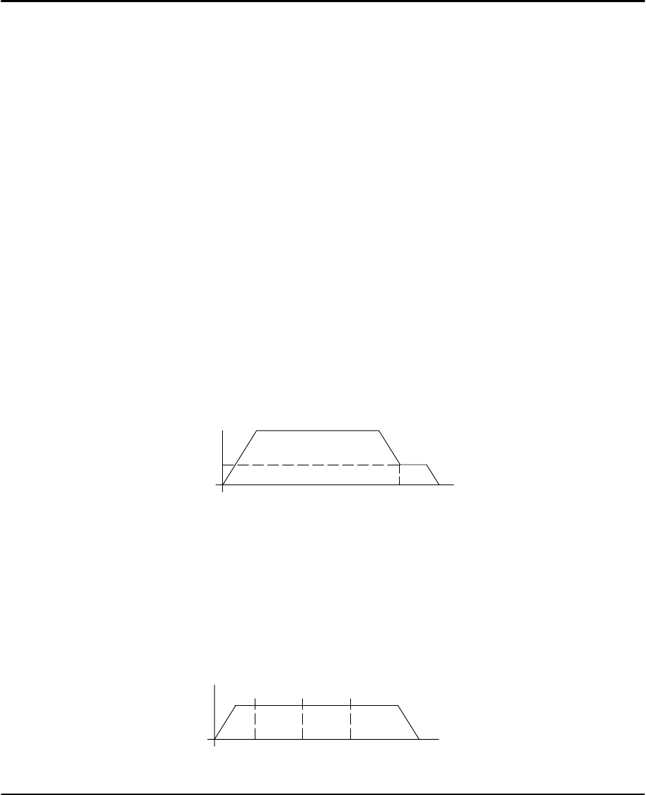
Keypad Programming 6-31MN1854
Create a Message and Read an Input Variable
[GET PARTS] Name the subroutine
MS1,“” Clears the Display
MS1,“How many?: ” Writes string beginning at character 1, top line
IV12,(PIECES) Waits at 12th character for the # of pieces.
MS1,“” Clears the Display
MS1,“How long?:: ” Writes string beginning at character 1, top line
IV12,(LENGTH) Waits at 12th character for the length.
LP(PIECES) Loops the number of pieces entered
DI(LENGTH) Moves the length entered.
GO EB
Create a Menu (menu display on keypad display for operator)
MS1,“” Clears keypad screen
MS21,“PART1 PART2 PART3”Writes a message above function keys.
FK1,2,3 Waits for a Function Key to be pressed
(FKEY)=(FKEY)+50 Add an offset to FKEY
GT(FKEY) Goto program #51, 52, or 53. (50 + 1, 2, or 3)
Fast In, Slow Feed Move (Using the Distance to Change (DC) command)
AC.05 Set acceleration
DE.09 Set deceleration
VE50 Set first velocity
DA6 Set total move distance
DC5.5 Set point where you want to change speed
VE5 Set second speed
GO Start the move profile
50
0
5.0
5.5 6.0
Setting an Output=On (on–the–fly)
AC.05 Set acceleration
VE10 Set velocity
DA4 Set total move distance
DC1 Set point to turn on...
OT1 Output 1
DC2 Set point to turn on...
OT2,1 Output 2
DC3 Set point to turn on...
OT3,1 Output 3
GO OT1,1
1
OT2,1
2
OT3,1
34

6-32 Keypad Programming MN1854
Read a 4 Digit BCD number, 2 Digits at a time
[GET 4 BCDS] Returns value of 4 digit BCD number
OT01 Connect ground of first two BCD digits
(4 DIGIT BCD)=(2TW)*100 Make value of first two digits the MSB
OT10 Connect ground of 2nd two BCD digits
(4 DIGIT BCD)=(4 DIGIT BCD)+(2TW) Add value of 2nd two to 1st two * 100
Reading an Analog Input Value
The value of the analog system variables (Al I –AI6) are scaled from 14,400 to 72,000 Hz.
This value is actually a scaled frequency read from the OPTO module representing the
analog signal. These input values are updated every 16 milliseconds. If your program
needs to display this value in units such as VOLTS, you will need to scale the value to
VOLTS in your program. The scaling factor depends upon the type of OPTO module used.
For example: a ”J ” thermocouple uses a different factor than a ”K” thermocouple. Due to
slight variances in the output frequency from module to module, it is recommended that the
OPTO be calibrated by querying the corresponding AIx value with no input signal connected
to the OPTO. This value should be used as the zero input reference frequency.
Example: Use a 0–10VDC analog input. 0V=14,400; 10V=72,000 or 5.760 Hz/volt.
(VOLT)=(AI2) Read the value of analog input #2 into variable volts
(VOLT)=(VOLT)–14400 Remove frequency offset
(VOLT)=(VOLT)*1.736 Scaling factor multiplied. by 10,000
(VOLT=(VOLT)*.0001 Scaling back to volts
The variable (VOLT) is now in units of volts. If you are waiting for a condition to occur or
doing a comparison, (see below) there is no need to go through the conversion process.
(TEMP)=(AI9) Read in temperature from analog input
WT(AI12)<45000 GO Wait for analog input 12 <45000 (<5.3 VDC using the
previous example) before moving
IF(AI12)<45000 GO EB Go if analog input 12 < 45000
Min
Value Max
Value
Input Signal
10
20
30
40
50
60
70
80 72
14.4
Output
Frequency
(kHz)

Section 7
Troubleshooting
Troubleshooting 7-1MN1854
Overview The system troubleshooting procedures involve observing the status of the LED’s.
The tables in this section provide information related to the indications provided by
these devices.Table 7-1 Operation Indicators
LED Color Status Comments
Power Green Indicates that AC power is applied and the
supplies are operating. LED’s will flash during power up tests but only
the Power LED should remain on.
Regen Yellow On during Regen activity. Should remain off. On when Regen circuit is
active to dump excess bus energy.
OverVoltage/
INTLK Red Regen circuit cannot handle excess energy or
Interlock circuit is open. This fault condition is reset by cycling power.
Temperature Red On when internal heatsink temperature exceeds
158°F (70°C). This fault condition is reset by cycling power.
Install a fan kit, reduce the load, reduce ambient
temperature, use the Standby current setting.
Table 7-2 Axis 1 and 2 Indicators
Stepping Green Indicates LinStep+ is sending CW (right LED) or
CCW (left LED) step pulses. Above several steps per second the LED
becomes continuously illuminated.
Disable/Short Yellow On when the Shutdown input is activated by an
external control. The Shutdown signal also
activates the Short output, but does not turn on
the Short LED.
Short LED indicates that a Short Circuit or
Undervoltage condition has occurred. A short
circuit problem can occur because of shorted
or miswired motor leads, or internal fault.
This fault condition is reset by cycling power.
To isolate the problem, disconnect and insulate
the motor leads from the drive connector, but
leave the Interlock jumper installed. Apply
power and step pulses. If the drive does not
invoke the short circuit fault, then it is likely that
the defect is in the motor, wires or the
connections at the drive.
Note: The fault LED and fault Output do NOT activate the same. The fault Output indicates that
one of several fault conditions has occurred. The fault LEDs provide a means of resolving
the source of the fault.
Additional Information (General)
Symptom Possible Cause Possible Remedies
The keypad is blank
with no backlight. The keypad is not receiving +5VDC. Verify all wiring is correct.
Verify that the +5VDC is between 4.8 and 5.2V.
Display is difficult to
read Contrast ratio is incorrectly set Adjust the contrast with the pot on the back of the keypad.
The ON LED is yellow. FLASH memory is corrupt. The operating system and user programs must be reloaded.
The ON LED is red. A Fault has occurred. The fault can be determined with the keypad or by using
serial status commands (SS, SA, SD).
Motor moves the wrong Wrong Gear Ratio. Check distance units
distance Motor stalled. Check motor current, inductance, anti–resonance settings
Check Speed Torque required for move, reduce
acceleration.
Motor stalls Acceleration and/or velocity too high. Reduce acceleration and/or velocity.
Motor configured incorrectly. Check motor current, inductance and anti–resonance
settings.
Motor direction is wrong The motor phases are miswired. Verify connections, or swap A+ with A–.
The system real direction is reversed. Change the control’s direction parameter.
The control does not re-
spond to keypad input. The keypad is disabled. Check the switch settings on the back of the keypad.
The motor “whines”The inductance or anti–resonance
setting is incorrect. Verify the Inductance setting. Operation is best with motors
4 mH or above. Otherwise, verify the anti–resonance setting.

7-2 Troubleshooting MN1854
Additional Information Continued
Symptom Possible Cause Possible Remedies
No RS232 commu-
nication but keypad
works.
If the keypad works, the RS232 port
is working. Something else is wrong
(wiring, configuration, address).
Refer to Section 5, “Configure Serial Communications”.
Verify PC COM port is set to 9600 baud, 8 data bits 1 stop bit,
no parity.
RS232 communica-
tion and keypad do The keypad is disabled. Verify that you do not have an RS485 version.
Enable the keypad by the switch on back of keypad.
tion and keypad do
not work. The serial port is not working. Contact Baldor.
“Hit A Limit” A limit switch has been activated. Either the motion commanded was not correct, or the EOT
switch is incorrectly positioned on your system.
“Amplifier Fault”Multiple drive faults have occurred. The fault can be determined with the keypad or by using serial
status commands (SS, SA, SD).
“Over Temperature
Fault”Internal Fan is not operating or
Heatsink Tunnel is clogged or
restricted.
Remove obstruction, or clean tunnel by removing unit, use
screwdriver to prevent the fan from turning, and blow shop
air through the tunnel. Return unit to installation.
Ambient air in cabinet is too hot. If multiple units are installed within the enclosure, ventilation
must be adequately to remove heat.
The fan does not operate. With power off, verify the internal fan connections. If properly
connected, the fan may have failed. Contact Baldor.
“Over Current Fault” Motor is miswired or damaged. The
LinStep+ has short circuit protection,
but you must correct the problem to
clear the fault.
With power off verify all connections.
Verify current setting is correct for the motor rating.
Verify the motor phases are not open or shorted (phase to
phase and phase to ground). The resistance in each phase
should be about the same and only a few ohms. If the
phases are open or have a large resistance, the motor is
probably damaged and should be replaced.
“Over Voltage Fault”Excessive bus voltage. Usually
caused by a regen condition that
overwhelms the internal power
dump circuit.
It can also be caused by high line
voltage, or voltage spikes.
Eliminate the regen event by reducing the load or make the
move less aggressively by reducing the commanded
acceleration or velocity.
Verify AC line voltage is within the limits.
“Interlock Fault”Motor connector does not have an
interlock jumper, or motor has been
disconnected.
Connect motor connector with Interlock.
“Following Error”Motor stalled. Confirm proper motor configuration (current, AR, mH).
Make a less aggressive move.
Wrong encoder resolution set. Verify the encoder settings are correct. Incorrect settings can
cause a following error.
“Encoder Wired
Backwards”Encoder position is changing opposite
the commanded move. Verify motor and encoder wiring. Reverse phases of either
motor or encoder. Contact Baldor for assistance.
“Encoder Fault”Attempted closed loop motion and
encoder position is unchanged. Verify encoder wiring.
“Error Finding Home” Both EOT switches were activated
without finding the home switch. Verify home switch connections and configuration (NORM
OPEN or NORM CLOSED).
“Invalid Program”Attempted to “call” an empty program
(i.e. GT, GS). Verify program number, or define program “called”.
“Program Too Large”Program length exceeds 1024 bytes. Divide program into smaller programs or reduce program size.
“Insufficient Memory”All stored user programs exceed 60K. Reduce program size, or delete programs.
“Invalid Program #”Program number exceeds 400 or
program name does not exist. Verify program name and number.

Troubleshooting 7-3MN1854
Additional Information Continued
Symptom Possible Cause Possible Remedies
“Unknown Command”A command not in the command set
has been issued. Check program for data entry errors.
“Command Is Too
Long”Command and parameter string
exceeds 80 characters. Reduce command string size.
“Too Many Parame-
ters”Parameter list exceeds amount
supported by command. Reduce parameter list size.
“Invalid Parameter”Parameter type is invalid. Verify parameter with command syntax.
“Bad Command
Syntax”Command and parameter list has
invalid syntax. Check program for data entry errors.
“Too Many Nested
LPs”Program exceeds 16 nested loops. Reduce nested loops.
“Too Many Nested
GSs”Program exceeds 16 nested gosubs. Reduce nested gosubs.
“Too Many Nested
EBs”Program exceeds 16 nested IF
blocks. Reduce number of nested IF blocks.
“Bad Variable Name”A variable used as a command
parameter is undefined (misspelled). Verify variable name, or define variable with an initial value.
“No Free Variables”Attempted to define more than 100
user variables. Reduce number of user variables.
Serial Communications Problems
1. Test your terminal or terminal emulation software. Disconnect the motor and transmit a character.
Receiving double characters (XX) when entering single characters (X), indicates your computer is
set to the half duplex mode. Change to the full duplex mode.
2. Host transmit (TX) must be connected to receive (RX) of the drive unit, and receive (RX) of the host
must be connected to transmit (TX) of the drive. If communication fails, try reversing these
connections at either the host or the LinStep.
3. Many serial ports require handshaking. Jumper RTS to CTS, and DSR to DTR at host connector
Jumpers 9 pin (25 pin) RTS to CTS 7 to 8 (4 to 5); DSR to DTR 4 to 6 (6 to 20).
4. Configure the host to the identical baud rate, number of data bits, number of stop bits, and parity.
5. Check all grounds. Use DC common or signal ground as your reference. Do not use earth ground
or shield.
6. Check your cable length. If any cable is over 50 ft. long, you should be using a line driver, optical
coupler, or shield. Shields must be connected to earth ground at one end only.

7-4 Troubleshooting MN1854

Section 8
Specifications & Product Data
Specifications & Product Data 8-1MN1854
Identification
1
Linear Stepper Driver
LX
LinStep+
Number Axes
1=1 Axis
2=2 Axis
P
Driver Type
D = LinStep
P = LinStep Plus
Input Voltage
1=115VAC
2=230VAC
2 A–06
Rated Output Current
06 = 6.9 Amperes

8-2 Specifications & Product Data MN1854
General Specifications
Description Unit LX2P1A06–2
Input Voltage Range Nominal
Minimum
Maximum
VAC 115
92
132
Input Frequency Hz 50/60 ±5%
Nominal Output Bus Nominal
(@ 115 / 230 input) Minimum
Maximum
VDC 170
88
220
Max. Output Current each axis ARMS 6
Resolution in (mm) 4 x 10⁻⁵ (1.016 x 10⁻³)
Efficiency % 85
Motor Inductance mH 2 – 60
Switching Frequency kHz 20
Encoder –Optically Isolated, differential line driver, 5VDC, 500 KHz Max (2
MHz post quadrature)
Inputs –8 – Programmable + 2 Limit and 1 Home inputs. (24VDC
maximum – optically isolated ≤ 3mA sink current at ≥ 0.7Volts)
Output Power –12VDC @ 12mA (Pull–ups)
5VDC @ 200mA (encoder)
Programmable Outputs –8 – Open collector (100mA maximum sink current,
350mA maximum total sink amps).
Programming –Keypad or Serial communications
Operating Temperature °F 〈°C) 32 to 100 (0 to 40); 122 (50) Maximum
Operating Altitude ft (m) 8300 (2540) Maximum
Storage Temperature °F 〈°C) –13 to 158 (–25 to 70)
Humidity (non–condensing) % 10–90
Shock 10G (according to DIN IEC 68–2–6/29)
Vibration 1G @ 10 – 150 Hz (according to DIN IEC 68–2–6/29)
Protection & Indicators Description
LED Indications Green – Normal operation; Red – Fault condition; Amber – FLASH
fault Protection
Short Circuit Disable on phase–to–phase, or phase–to–ground detected
Undervoltage Disable if supply drops below 90 VAC
Over Temperature Disable if heatsink > 70 °C
Interlock Disable if interlock connection broken
Regen/Overvoltage Disable if bus voltage exceeds 220 VAC on 115 VAC units, 440 VAC
on 230 VAC unit
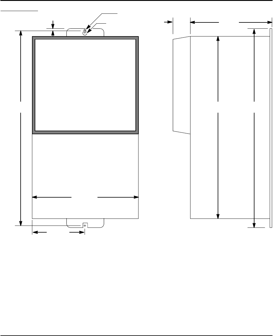
Specifications & Product Data 8-3MN1854
Dimensions
10.08
(256.0)
0.20 (5.1)
0.34 (8.7)
10.50
(266.7)
2.93
(74.4)
5.84
(148.3)
3.73
(94.7)
0.21 (5.3)
2 Axis
Driver
1.19
(30.2)
Use 8–32 or 10–32 Cap Screws (2 places)
9.06
(230.1)
(Optional Keypad)
For safe operation, allow a clearance distance between each control and on all sides of each control.
At least 3 inches (75mm) top and bottom clearance must be provided for air flow. Between drivers
(each side), allow at least 0.1 inch (2.5mm).

8-4 Specifications & Product Data MN1854

Section 9
CE Guidelines
CE Guidelines 9-1MN1854
CE Declaration of Conformity
Baldor indicates that the products are only components and not ready for
immediate or instant use within the meaning of “Safety law of appliance”, “EMC
Law” or “Machine directive”.
The final mode of operation is defined only after installation into the user’s
equipment. It is the responsibility of the user to verify compliance.
The product conforms with the following standards:
DIN VDE 0160 / 05.88 Electronic equipment for use in electrical power
installations
DIN VDE 0100 Erection of power installations with nominal
voltages up to 1000V
DIN IEC 326 Teil 1 / 10.90 Design and use of printed boards
DIN VDE 0110Teil 1-2 / 01.89 Dimensioning of clearance and creepage
DIN VDE 0110Teil 20 / 08.90 distances
EN 60529 / 10.91 Degrees of protection provided by enclosures
EMC – Conformity and CE – Marking
The information contained herein is for your guidance only and does not
guarantee that the installation will meet the requirements of the council directive
89/336/EEC.
The purpose of the EEC directives is to state a minimum technical requirement
common to all the member states within the European Union. In turn, these
minimum technical requirements are intended to enhance the levels of safety both
directly and indirectly.
Council directive 89/336/EEC relating to Electro Magnetic Compliance (EMC)
indicates that it is the responsibility of the system integrator to ensure that the
entire system complies with all relative directives at the time of installing into
service.
Motors and controls are used as components of a system, per the EMC directive.
Hence all components, installation of the components, interconnection between
components, and shielding and grounding of the system as a whole determines
EMC compliance.
The CE mark does not inform the purchaser which directive the product complies
with. It rests upon the manufacturer or his authorized representative to ensure the
item in question complies fully with all the relative directives in force at the time of
installing into service, in the same way as the system integrator previously
mentioned. Remember, it is the instructions of installation and use, coupled with
the product, that comply with the directive.
Wiring of Shielded (Screened) Cables
Conductive
Clamp
Remove the outer
insulation to expose the
overall screen.
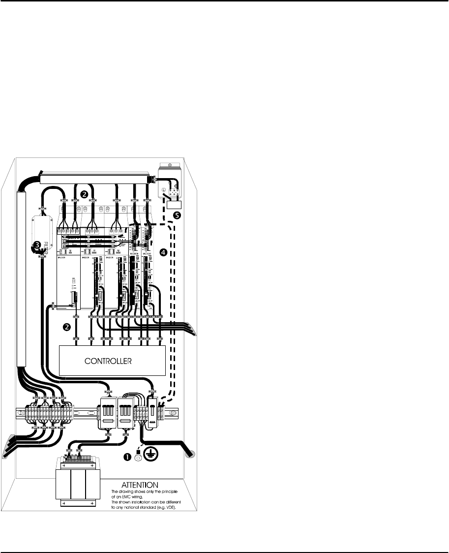
9-2 CE Guidelines MN1854
Using CE approved components will not guarantee a CE compliant system!
1. The components used in the drive, installation methods used, materials
selected for interconnection of components are important.
2. The installation methods, interconnection materials, shielding, filtering
and grounding of the system as a whole will determine CE compliance.
3. The responsibility of CE mark compliance rests entirely with the party
who offers the end system for sale (such as an OEM or system
integrator).
Baldor products which meet the EMC directive requirements are indicated with a
“CE” mark. A duly signed CE declaration of conformity is available from Baldor.
EMC Wiring Technique 1CABINET
The drawing shows an electroplated zinc coated enclosure,
which is connected to ground.
This enclosure has the following advantages:
– All parts mounted on the back plane are connected to
ground.
– All shield (screen) connections are connected to ground.
Within the cabinet there should be a spatial separation
between power wiring (motor and AC power cables) and
control wiring.
2SCREEN CONNECTIONS
All connections between components must use shielded
cables. The cable shields must be connected to the
enclosure. Use conductive clamps to ensure good ground
connection. With this technique, a good ground shield can
be achieved.
3EMC – FILTER
The EMI or main filter should be mounted next to the power
supply (here BPS). For the connection to and from the main
filter screened cables should be used. The cable screens
should be connected to screen clamps on both sides.
(Exception: Analog Command Signal).
4Grounding (Earth)
For safety reasons (VDE0160), all BALDOR components
must be connected to ground with a separate wire. The
diameter of the wire must be at minimum AWG#6 (10mm@).
Ground connections (dashed lines) must be made from the
central ground to the regen resistor enclosure and from the
central ground to the Shared Power Supply.
5Y–CAPACITOR
The connection of the regeneration resistor can cause RFI
(radio frequency interference) to be very high. To minimize
RFI, a Y–capacitor is used. The capacitor should only be
connected between the dynamic brake resistor housing
and terminal pin R1 (lead from Flex).
Recommend: 0,1µF / 250VAC Type: PME265
BALDOR–Ordering–No.: ASR27104
Y
Ca
pa
cit
or
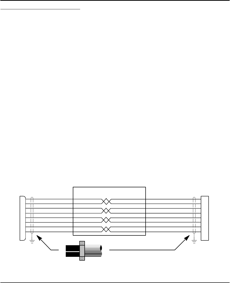
CE Guidelines 9-3MN1854
EMC Installation Instructions
To ensure electromagnetic compatibility (EMC), the following installation
instructions should be completed. These steps help to reduce interference.
Consider the following:
•Grounding of all system elements to a central ground point
•Shielding of all cables and signal wires
•Filtering of power lines
A proper enclosure should have the following characteristics:
A) All metal conducting parts of the enclosure must be electrically
connected to the back plane. These connections should be made with a
grounding strap from each element to a central grounding point .
B) Keep the power wiring (motor and power cable) and control wiring
separated. If these wires must cross, be sure they cross at 90 degrees to
minimize noise due to induction.
C) The shield connections of the signal and power cables should be
connected to the screen rails or clamps. The screen rails or clamps
should be conductive clamps fastened to the cabinet.
D) The cable to the regeneration resistor must be shielded. The shield must
be connected to ground at both ends.
E) The location of the AC mains filter has to be situated close to the drive
so the AC power wires are as short as possible.
F) Wires inside the enclosure should be placed as close as possible to
conducting metal, cabinet walls and plates. It is advised to terminate
unused wires to chassis ground.
G) To reduce ground current, use at least a 10mm2 (6 AWG) solid wire for
ground connections.
Grounding in general describes all metal parts which can be connected to a protective
conductor, e.g. housing of cabinet, motor housing, etc. to a central ground point. This
central ground point is then connected to the main plant (or building) ground.
Or run as twisted pair at minimum.
Cable Screens Grounding
Cable (Twisted Pair Conductors)
Conductive Clamp – Must contact bare cable shield
and be secured to metal backplane.
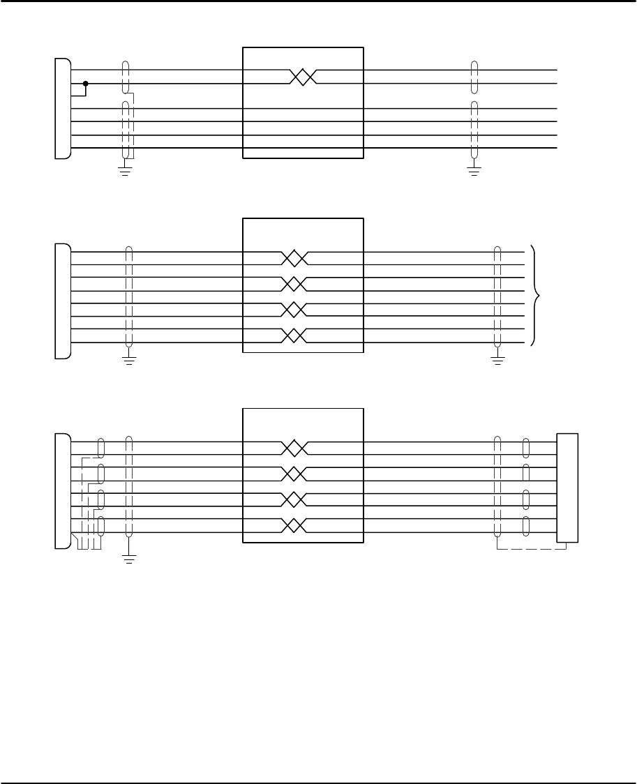
9-4 CE Guidelines MN1854
Input Signal Cable Grounding
Cable
1
2
3
7
9
10
11
Control
Simulated Encoder Output Cable Grounding
Cable
1
6
2
7
3
8
11
13
Control
To
Controller
Encoder Cable Grounding
Cable
1
6
2
7
3
8
11
13
Control Encoder Connector
Housing
Connection of shields to digital ground is optional.

Appendix A
Appendix A-1MN1854
Programming Template
1 234567891011 12 13 14 15 16 17 18 19 20
21 22 23 24 25 26 27 28 29 30 31 32 33 34 35 36 37 38 39 40
FK1 FK2 FK3
1 234567891011 12 13 14 15 16 17 18 19 20
21 22 23 24 25 26 27 28 29 30 31 32 33 34 35 36 37 38 39 40
FK1 FK2 FK3
1 234567891011 12 13 14 15 16 17 18 19 20
21 22 23 24 25 26 27 28 29 30 31 32 33 34 35 36 37 38 39 40
FK1 FK2 FK3
1 234567891011 12 13 14 15 16 17 18 19 20
21 22 23 24 25 26 27 28 29 30 31 32 33 34 35 36 37 38 39 40
FK1 FK2 FK3

A-2 Appendix MN1854
1 2 3 4 5 6 7 8 9 10 11 12 13 14 15 16 17 18 19 20
21 22 23 24 25 26 27 28 29 30 31 32 33 34 35 36 37 38 39 40
FK1 FK2 FK3
1 2 3 4 5 6 7 8 9 10 11 12 13 14 15 16 17 18 19 20
21 22 23 24 25 26 27 28 29 30 31 32 33 34 35 36 37 38 39 40
FK1 FK2 FK3
1 2 3 4 5 6 7 8 9 10 11 12 13 14 15 16 17 18 19 20
21 22 23 24 25 26 27 28 29 30 31 32 33 34 35 36 37 38 39 40
FK1 FK2 FK3
1 2 3 4 5 6 7 8 9 10 11 12 13 14 15 16 17 18 19 20
21 22 23 24 25 26 27 28 29 30 31 32 33 34 35 36 37 38 39 40
FK1 FK2 FK3

Appendix A-3MN1854
1 2 3 4 5 6 7 8 9 10 11 12 13 14 15 16 17 18 19 20
21 22 23 24 25 26 27 28 29 30 31 32 33 34 35 36 37 38 39 40
FK1 FK2 FK3
1 2 3 4 5 6 7 8 9 10 11 12 13 14 15 16 17 18 19 20
21 22 23 24 25 26 27 28 29 30 31 32 33 34 35 36 37 38 39 40
FK1 FK2 FK3
1 2 3 4 5 6 7 8 9 10 11 12 13 14 15 16 17 18 19 20
21 22 23 24 25 26 27 28 29 30 31 32 33 34 35 36 37 38 39 40
FK1 FK2 FK3
1 2 3 4 5 6 7 8 9 10 11 12 13 14 15 16 17 18 19 20
21 22 23 24 25 26 27 28 29 30 31 32 33 34 35 36 37 38 39 40
FK1 FK2 FK3
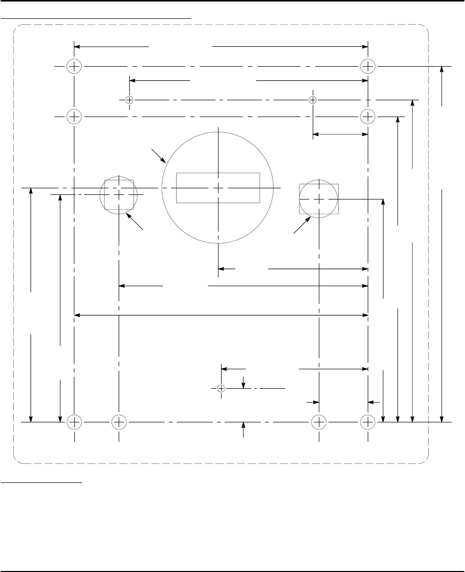
A-4 Appendix MN1854
Remote Keypad Mounting Template
0.23
(5.84)
2.0 (50.8)
0.66
(16.7)
3.09
(78.48)
3.184
(80.87)
3.25 (82.55)
0.75
(19.0)
4.0 (101.6)
2.04
(51.8)
3.39
(86.10)
3.034 (77.06)
4.154 (105.51)
4.380 (111.25)
4.838 (122.88)
EE
EE
MM
MM
B
BB
0.5 (12.7)
Cut–Out
1.5 (38.1)
Cut–Out
0.5 (12.7)
Cut–Out
Installation Notes.
1. For SAE mounting (6–32 hardware) mark and drill holes “E” with 3/16" drill bit.
2. For metric mounting (M3.5 hardware) mark and drill holes “M” with 3/16" drill bit.
3. For Ball–Head Removable mounting mark and drill holes “B” with 5/32" drill bit.
4. To prevent damage to keypad, mounting screws must not extend more than 0.2" into keypad.
5. To isolate the keypad from the enclosure, use non–conductive mounting hardware.

BALDOR ELECTRIC COMPANY
P.O. Box 2400
Ft. Smith, AR 72902–2400
(501) 646–4711
Fax (501) 648–5792
www.baldor.com
W Baldor Electric Company
MN1854 Printed in USA
7/01 C&J 1000
CH
TEL: +41 52 647 4700
FAX: +41 52 659 2394
D
TEL: +49 89 90 50 80
FAX: +49 89 90 50 8491
UK
TEL: +44 1454 850000
FAX: +44 1454 850001
I
TEL: +39 11 562 4440
FAX: +39 11 562 5660
AU
TEL: +61 29674 5455
FAX: +61 29674 2495
F
TEL: +33 145 10 7902
FAX: +33 145 09 0864
CC
TEL: +65 744 2572
FAX: +65 747 1708
MX
TEL: +52 47 61 2030
FAX: +52 47 61 2010

LinStep+ Dual–Axis Microstepping Indexer/Driver MN1854
