Users Manual

HF-CNTL-PBS- 0 2 I N S T A L L A T I O N G U I D E – R E V . 0 3 P A G E 1 O F 2 3
COBALT HF-CNTL-PBS-02
RFID CONTROLLER
High Frequency Passive Radio Frequency Identification Controller
IN ST A L L AT IO N GU I D E
How to Install and Setup
Cobalt HF-CNTL-PBS-02 RFID Controller
HF-CNTL-PBS-02 INSTALLATION GUIDE – REV. 03
Copyright © 2010 Datalogic Automation S.r.l., all rights reserved
HF-CNTL-PBS- 0 2 I N S T A L L A T I O N G U I D E – R E V . 0 3 P A G E 2 O F 2 3
REGULATORY COMPLIANCE
FCC COMPLIANCE
Modifications or changes to this equipment without the expressed written approval of
Datalogic could void the autority to use the equipment.
This device complies with PART 15 of the FCC Rules.
Operation is subject to the following two conditions: (1) This device may not cause
harmful interference, and (2) this device must accept any interference that may cause
undesired operation.
FCC ID : E36-0002
NOTE:
This equipment has been tested and found to comply with the limits for a Class B
digital device, pursuant to Part 15 of the FCC Rules. These limits are designed to
provide reasonable protection against harmful interference in a residential installation.
This equipment generates, uses and can radiate radio frequency energy and, if not
installed and used in accordance with the instructions, may cause harmful interference
to radio communications. However, there is no guarantee that interference will not
occur in a particular installation. If this equipment does cause harmful interference to
radio or television reception, which can be determined by turning the equipment off
and on, the user is encouraged to try to correct the interference by one or more of
the following measures:
-- Reorient or relocate the receiving antenna.
-- Increase the separation between the equipment and receiver.
-- Connect the equipment into an outlet on a circuit different from that to which the
receiver is connected.
-- Consult the dealer or an experienced radio/TV technician for help.

HF-CNTL-PBS- 0 2 I N S T A L L A T I O N G U I D E – R E V . 0 3 P A G E 3 O F 2 3
RADIO COMPLIANCE
ENGLISH
Contact the competent authority responsible for the management of radio frequency
devices of your country to verify any possible restrictions or licenses required. Refer to
the web site:
http://ec.europa.eu/enterprise/sectors/rtte/ for further information.
ITALIANO
Prendi contatto con l'autorità competente per la gestione degli apparati a radio
frequenza del tuo paese, per verificare eventuali restrizioni o licenze. Ulteriori
informazioni sono disponibili sul sito:
http://ec.europa.eu/enterprise/sectors/rtte/
FRANÇAIS
Contactez l'autorité compétente en la gestion des appareils à radio fréquence de votre
pays pour vérifier d'éventuelles restrictions ou licences. Pour tout renseignement vous
pouvez vous adresser au site web:
http://ec.europa.eu/enterprise/sectors/rtte/
DEUTSCH
Wenden Sie sich an die für Radiofrequenzgeräte zuständige Behörde Ihres Landes,
um zu prüfen ob es Einschränkungen gibt, oder eine Lizenz erforderlich ist. Weitere
Informationen finden Sie auf der Web Seite:
http://ec.europa.eu/enterprise/sectors/rtte/
ESPAÑOL
Contacta la autoridad competente para la gestión de los dispositivos de radio
frecuencia de tu país, para verificar cualesquiera restricciones o licencias posibles
requerida. Además se puede encontrar mas información en el sitio Web:
http://ec.europa.eu/enterprise/sectors/rtte/
POWER SUPPLY
This product is intended to be installed by Qualified Personnel only.
This device is intended to be supplied by a UL Listed or CSA Certified Power Unit with
«Class 2» or LPS power source

HF-CNTL-PBS- 0 2 I N S T A L L A T I O N G U I D E – R E V . 0 3 P A G E 4 O F 2 3
CHAPTER 1:
CONTROLLER INFORMATION
1 . 1 H F - C N T L - P B S - 0 2 OV E R V I E W
Welcome to the Cobalt HF-CNTL-PBS-02 RFID Controller – Installation Guide, this
document will assist you in the installation and setup of the Cobalt HF-CNTL-PBS-02
RFID Controller.
The Cobalt HF-CNTL-PBS-02 is a feature-rich, high frequency, Radio-Frequency
Identification device that provides read/write RFID data transmission and control
solutions to shop floor, item-level tracking and material handling applications.
The controller is designed to be compact, rugged and reliable, in order to meet and
exceed the requirements of the industrial automation industry.
1.1.1 Package Contents
Unpack the Cobalt Controller hardware and accessories. Retain the original shipping
carton and packing material in case any items need to be returned. Inspect each piece
carefully, if an item appears to be damaged, notify your EMS product distributor.
The Cobalt HF-CNTL-PBS-02 RFID Controller product package contains the following
components:
PART NUM BER QTY DESCRIPTION
HF-CNTL-PBS-02 1 Cobalt HF-Series RFID Controller (-PBS)
17-3126 1 HF-CNTL-PBS-02 Installation Guide
20-1950 2 Screw (Socket Head Cap, M5 x 20mm, Hex #4,
18-8 SS)
20-3915 2 Washer (Spring Lock, M5, 18-8 SS)
69-1289 1 Wrench Tool (Hex #4, 4mm, L-key)
00-3000 1 Cobalt HF-Series Configuration Tag
CBL-1487 1 Field Mountable Connector (Straight, 5-pos,
Female, M12 - for connecting power)
Table 1-1: HF-CNTL-PBS-02 - Package Contents
HF-CNTL-PBS- 0 2 I N S T A L L A T I O N G U I D E – R E V . 0 3 P A G E 5 O F 2 3
1.1.2 Power & Communications Interface
Connection Type: Profibus
Communication Interface: Profibus - DP
Data Interface Connector: 5-pin, male M12
Connector (for
Profibus data)
5-pin, female M12
Connector (for
Profibus data)
Power Interface Connector: 5-pin, Male, M12 (for power)
Additional Connector: 8-pin, Male M12 Connector for RS232
configuration support
Maximum Cable Length: 100m
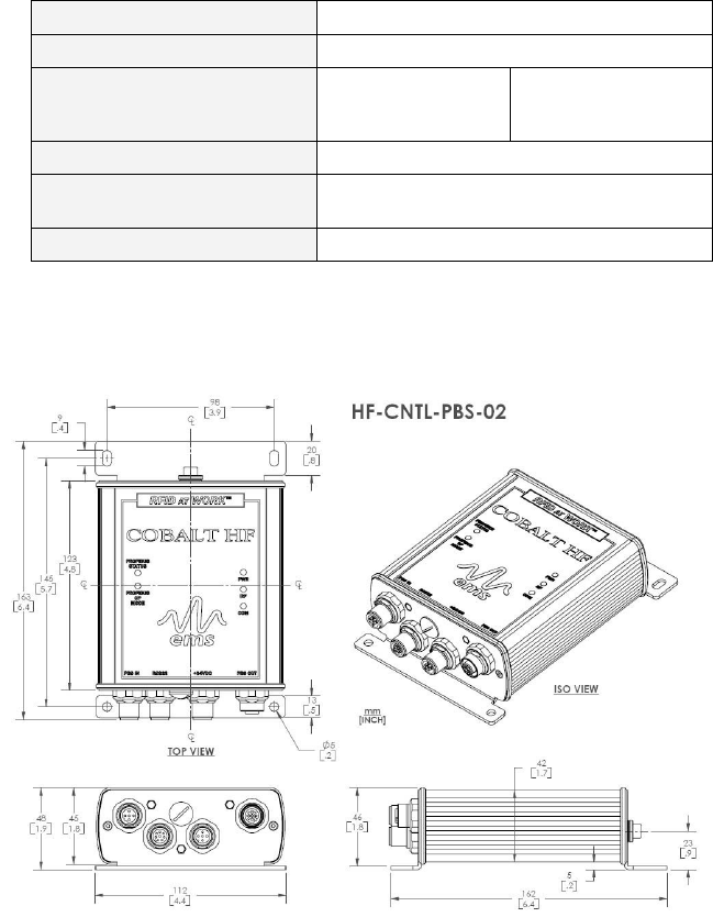
1.1.3 HF-CNTL-PBS-02 Controller Dimensions
Figure 1-1: HF-CNTL-PBS-02 Controller Dimensions
HF-CNTL-PBS- 0 2 I N S T A L L A T I O N G U I D E – R E V . 0 3 P A G E 6 O F 2 3
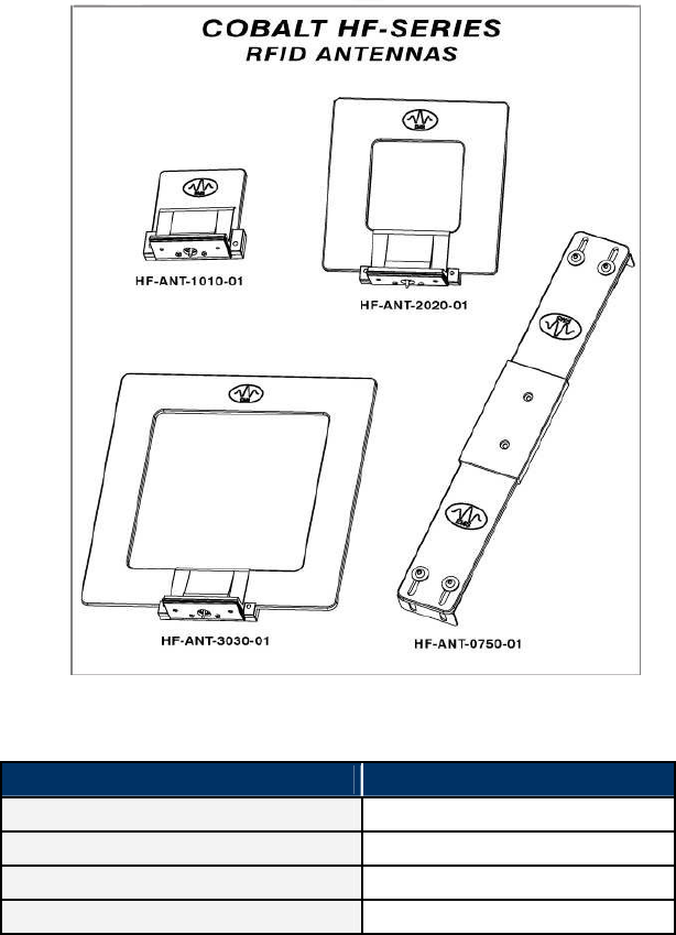
1 . 2 CO B A L T H F - S E R I E S R F I D AN T E N N A S
The Cobalt HF product family currently includes four different RFID
antenna models. Because Cobalt HF Antennas are designed with
different dimensions, they each generate unique RF field pattern and
read/write range.
Figure 1-2: Cobalt HF-Series RFID Antennas
COBALT HF RFID ANTENNAS – MODELS AND SIZES
ANTENNA MODEL ANTENNA SIZE
HF-ANT-1010-01 10cm x 10cm
HF-ANT-2020-01 20cm x 20cm
HF-ANT-3030-01 30cm x 30cm
HF-ANT-0750-01 7cm x 50cm
Table 1-2: Cobalt HF RFID Antennas – Models and Sizes
HF-CNTL-PBS- 0 2 I N S T A L L A T I O N G U I D E – R E V . 0 3 P A G E 7 O F 2 3
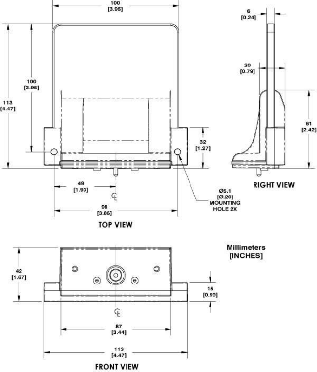
1.2.1 HF-ANT-1010-01 Antenna Dimensions
Figure 1-3: HF-ANT-1010-01 Antenna Dimensions
HF-CNTL-PBS- 0 2 I N S T A L L A T I O N G U I D E – R E V . 0 3 P A G E 8 O F 2 3
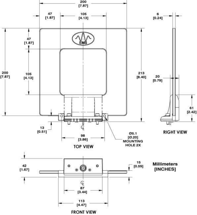
1.2.2 HF-ANT-2020-01 Antenna Dimensions
Figure 1-4: HF-ANT-2020-01 Antenna Dimensions
HF-CNTL-PBS- 0 2 I N S T A L L A T I O N G U I D E – R E V . 0 3 P A G E 9 O F 2 3
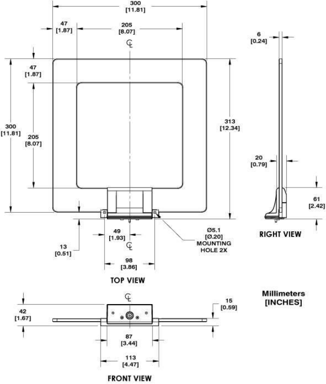
1.2.3 HF-ANT-3030-01 Antenna Dimensions
Figure 1-5: HF-ANT-3030-01 Antenna Dimensions
HF-CNTL-PBS- 0 2 I N S T A L L A T I O N G U I D E – R E V . 0 3 P A G E 1 0 O F 2 3
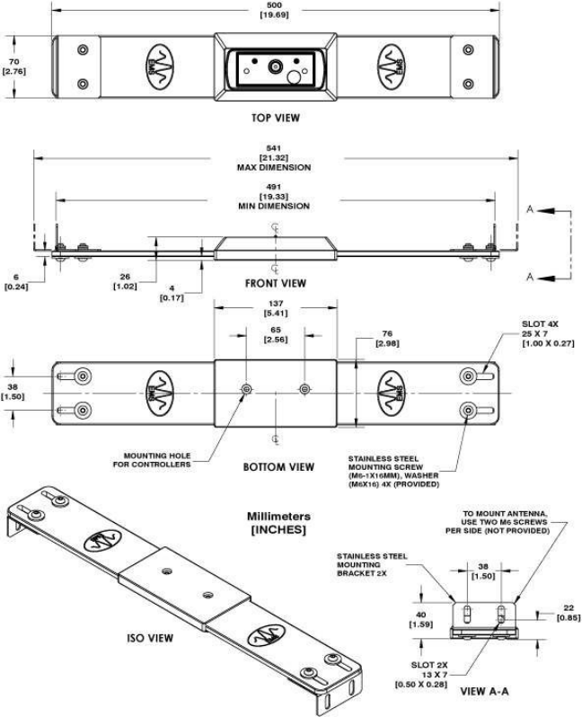
1.2.4 HF-ANT-0750-01 Antenna Dimensions
Figure 1-6: HF-ANT-0750-01 Antenna Dimensions

HF-CNTL-PBS- 0 2 I N S T A L L A T I O N G U I D E – R E V . 0 3 P A G E 1 1 O F 2 3
CHAPTER 2:
CONTROLLER INSTALLATION
2 . 1 PR E P A R I N G F O R IN S T A L L A T I O N
2.1.1 Power Requirements
The Cobalt Controller requires an electrical DC supply voltage. See Technical
Specifications for details. Use a dedicated and regulated power supply connected to a
suitable AC power source that is capable of delivering these requirements. Do not
apply power until the entire system is wired and checked.
2.1.2 Installation Guidelines
• RF performance and read/write range can be negatively impacted by the
proximity of metallic objects. Avoid mounting the antenna within 15cm (6
inches) of any metallic object or surface.
• Do not route cables near unshielded cables or near wiring carrying high
voltage or high current. Cross cables at perpendicular intersections and
avoid routing cables near motors and solenoids.
• Avoid mounting the controller near sources of EMI (electro-magnetic
interference) or near devices that generate high ESD (electro-static
discharge) levels.
• If electrical interference is encountered (as indicated by a reduction in
read/write performance), relocate the controller to an area free from
potential sources of interference.
• Conduct a test phase where you will construct a small scale, independent
network that includes only the essential devices required to test your RFID
application. To avoid possible interference with other devices, do not initially
connect your RFID testing environment to an existing local area network.
• Always use adequate ESD prevention measures to dissipate potentially high
voltages.
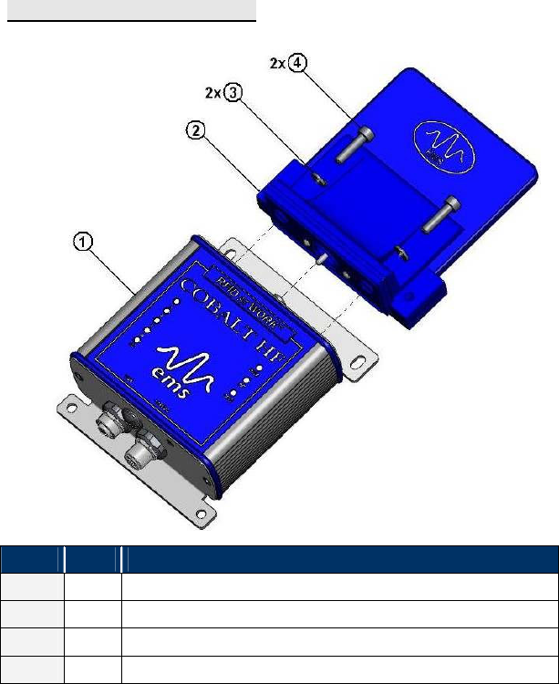
2 . 2 CO N N E C T I N G T H E AN T E N N A
Cobalt HF-Series RFID Antennas mount directly to the top of the Cobalt HF-Series
RFID Controller’s housing. The antenna is first attached to the RF port on the
controller and is then fastened to the controller’s housing using the two M5 screws and
matching spring lock washers included with each Cobalt HF-Series RFID Controller.
Use the provided 4mm hex key wrench to tighten both M5 screws.
TORQUE SPECIFICAT IO N
Screws should be tightened to the following torque setting:
HF-CNTL-PBS- 0 2 I N S T A L L A T I O N G U I D E – R E V . 0 3 P A G E 1 2 O F 2 3
1.7 Nm or 15 lbs / inch ± 10%
ITEM QTY DESCRIPTION
1 1 Cobalt Controller (HF-CNTL-PBS-02)
2 1 Cobalt Antenna (HF-ANT-1010-01)
3 2 Washer (Spring Lock, M5, 18-8 SS)
4 2 Screw (Socket Head Cap, M5 X 20mm, 18-8 SS)

HF-CNTL-PBS- 0 2 I N S T A L L A T I O N G U I D E – R E V . 0 3 P A G E 1 3 O F 2 3
2.2.1 Minimum Distance between Antennas
When installing multiple Cobalt HF-Series Controllers/Antennas, refer to the table
below to determine the recommended minimum distance to maintain between
adjacent Cobalt Antennas.
COB ALT
ANTENNA -1010 -2020 -3030 -0750
-1010 60cm 75cm 90cm 50cm
-2020 75cm 90cm 1.2m 65cm
-3030 90cm 1.2m 2m 90cm
-0750 50cm 65cm 90cm 50cm
Table 2-1: Minimum Distance between Antennas
For example, an HF-ANT-3030 RFID Antenna and an HF-ANT-1010 RFID Antenna
should be located no closer than 90 centimeters apart.

HF-CNTL-PBS- 0 2 I N S T A L L A T I O N G U I D E – R E V . 0 3 P A G E 1 4 O F 2 3
2 . 3 IN S T A L L I N G T H E H F - C N T L - P B S - 0 2
Note: review Section 2.1.2: “Installation Guidelines” prior to installing the
controller.
1. Attach the Cobalt HF Antenna to the Cobalt HF Controller as per the
instructions in Section 2.2: “Connecting the Antenna.”
2. Select a suitable location for the Cobalt HF Controller/Antenna. If
necessary, fabricate mounting brackets from durable plastic.
3. Fasten combined controller and antenna to your mounting fixture using two
M5 (#10) diameter screws (not included). Pass screws through antenna’s
mounting holes and secure them with appropriate washers and nuts.
Tighten screws to 1.7 Nm or 15 lbs per inch ± 10%.
4. Connect the three wires from your power supply to pins 1-3 on the 5-pin,
female, M12 connector (P/N: CBL-1487 included).
5. Attach the CBL-1487 connector to the 5-pin, male, M12 connector on the
Cobalt Controller.
6. Attach a Profibus-compatible data cable (P/N: CBL-1438-XX not included)
to the 5-pin, male M12 interface connector on the Cobalt. Connect the other
end of this cable to your Profibus network.
7. Turn your power supply ON. The green PWR (power) LED on the Cobalt will
illuminate. After the boot process is complete, The two “Profibus” LEDs on
the controller may appear green or off depending on the status of the
connection with your Profibus network.
OPTIONAL STEPS FOR ADDITIONAL CONFIGURATION
Steps 9 through 11 below are considered optional and only need to be
completed by users that wish to modify their Cobalt controller’s internal
configuration.
8. To modify the controller’s internal configuration, connect an 8-pin, RS232-
compatible, serial interface cable to the 8-pin, male M12 interface connector
on the Cobalt. Connect the other end of this cable to a COM port on your
host computer.
9. On the host computer, set COM port parameters to the following values:

HF-CNTL-PBS- 0 2 I N S T A L L A T I O N G U I D E – R E V . 0 3 P A G E 1 5 O F 2 3
COM PORT P ARAME TER DEF AULT V ALUE
Baud 9600
Data Bits 8
Stop Bits 1
Parity None
Handshaking None
Table 2-2: HF-CNTL-PBS-02 COM Port Default Settings
10. Download the Cobalt Dashboard Utility from www.ems-rfid.com and install
the software on your host computer. Use the Dashboard Utility to connect,
via RS232 serial connection, to the controller. You will then be able to use
the Cobalt HF Dashboard Utility to configure the Cobalt and send RFID
commands for testing purposes.
HF-CNTL-PBS- 0 2 I N S T A L L A T I O N G U I D E – R E V . 0 3 P A G E 1 6 O F 2 3
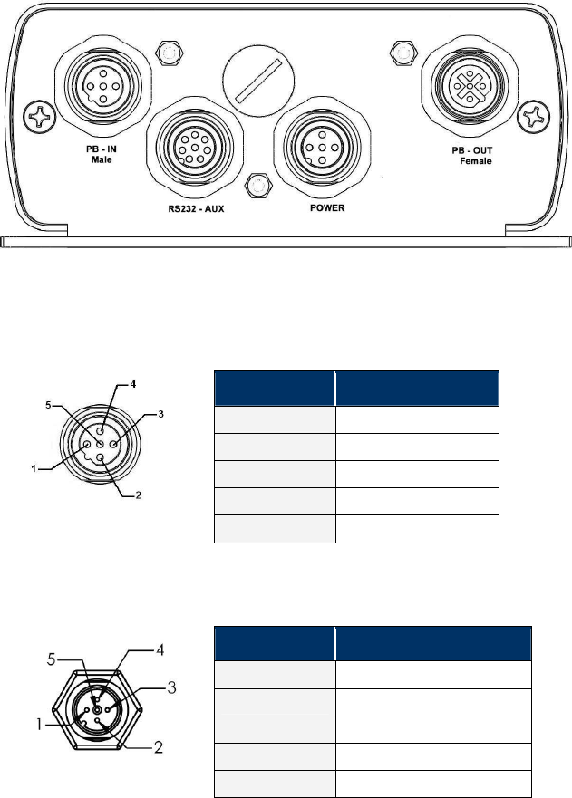
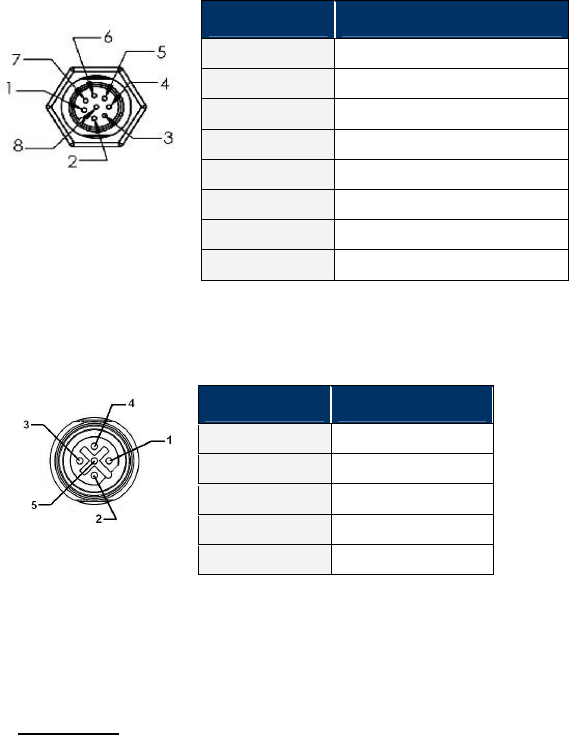
2 . 4 CA B L I N G IN F O R M A T I O N
Figure 2-1: 5-Pin, Male, M12 Connector (Profibus); 8-Pin, Male M12 Connector (for RS232
configuration); 5-Pin, Male, M12 Connector (Power) & 5-Pin, Female, M12 Connector
(Profibus)
5-PIN MALE M12 CONNECTOR – PROFIBUS
Table 2-4: 5-Pin, Male, M12 Connector (Profibus)
5-PIN MALE M12 CONNECTOR - POWER
Table 2-5: 5-Pin, Male, M12 Connector (Power)
PIN # DESCRIPTION
1 NOT CONNECTED
2 BUS – A
3 NOT CONNECTED
4 BUS – B
5 SHIELD
PIN # DESCRIPTION
1 NOT CONNECTED
2 +VDC POWER
3 0VDC (POWER GROUND)
4 NOT CONNECTED
5 NOT CONNECTED
HF-CNTL-PBS- 0 2 I N S T A L L A T I O N G U I D E – R E V . 0 3 P A G E 1 7 O F 2 3
8-PIN MALE M12 CONNECTOR – RS232 CONFIGURATION
Table 2-6: 8-Pin, Male M12 Connector (for RS232 configuration)
5-PIN FEMALE M12 CONNECTOR - PROFIBUS
Table 2-7: 5-Pin, Female, M12 Connector (Profibus)
HF-CNTL-PBS-02 CABLING PART NUMBERS
CBL-1438-XX: (Cable Profibus 12MM M/F)
(XX = Cable Length in Meters)
PIN # DESCRIPTION
1 NOT CONNECTED
2 NOT CONNECTED
3 NOT CONNECTED
4 NOT CONNECTED
5 NOT CONNECTED
6 RX (connects to PC TX)
7 TX (connects to PC RX)
8 SGND (SIGNAL GROUND)
PIN # DESCRIPTION
1 5 VDC
2 BUS – A
3 GROUND
4 BUS – B
5 SHIELD
HF-CNTL-PBS- 0 2 I N S T A L L A T I O N G U I D E – R E V . 0 3 P A G E 1 8 O F 2 3
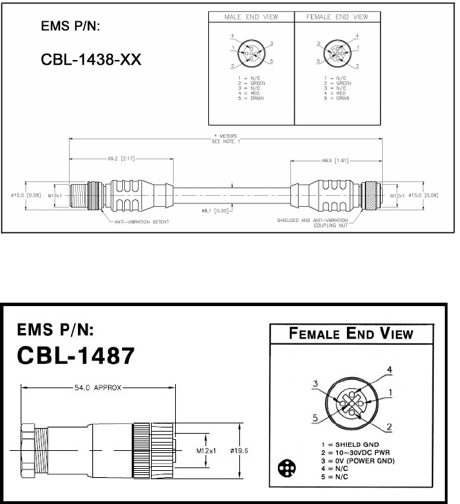
2.4.1 Profibus Interface Cable Schematic
Figure 2-2: CBL-1438-XX (Cable Profibus 12MM, 5-Pin, M/F)
Figure 2-3: CBL-1487 (5-Pin, Female, M12, Straight Field Mountable Connector)

HF-CNTL-PBS- 0 2 I N S T A L L A T I O N G U I D E – R E V . 0 3 P A G E 1 9 O F 2 3
ATTENTION:
For operating instructions for the HF-CNTL-PBS-02 RFID Controller, refer to the:
Cobalt HF-Series RFID Controllers – Operator’s Manual
available online at: www.ems-rfid.com.
Also available online at www.ems-rfid.com is Escort Memory Systems’ Cobalt
Dashboard™ software utility. The RFID Dashboard is a Windows-based application
that provides users with complete control over their EMS RFID hardware. Users can
monitor their entire RFID system - from the tag level, to the RFID Controller, to the
Host.

HF-CNTL-PBS- 0 2 I N S T A L L A T I O N G U I D E – R E V . 0 3 P A G E 2 0 O F 2 3
CHAPTER 3:
TECHNICAL SPECIFICATIONS
3 . 1 C O B AL T H F C O N T R O L L E R S
ELECTRICAL
DC input Voltage Range 12-30VDC
DC Input Current 500-300mA
RADIO
Frequency 13,56MHz
Air Interface ISO15693, ISO14443
Conducted Output Power 1W
COMMUNICATION
HF-CNTL-PBS-02 PROFIBUS-DP
Max cable length : 100m
MECHANICAL
Dimensions 163mm (6.4 inches) H x 112mm (4.4
inches) L x 46mm (1.8 inches) W
Weight 0.56 Kg (0.97 lb., 560 grams)
Enclosure Powder-coated Aluminum

HF-CNTL-PBS- 0 2 I N S T A L L A T I O N G U I D E – R E V . 0 3 P A G E 2 1 O F 2 3
ENVIRONMENTAL
Operating Temperature -20° to 50°C ( -4° to 122°F )
Storage Temperature -20° to +70°C ( -4° to 158°F )
Humidity 90% non-condensing
Protection Class IP65
3 . 2 H F A N T E N N A S
ELECTRICAL
All models
Frequency 13,56MHz
Input Impedence 50 ohm
Gain HF-ANT-1010-1 -36,6dBi
Gain HF-ANT-2020-1 -26,3dBi
Gain HF-ANT-3030-1 -22,9dBi
Gain HF-ANT-0750-1 -37,8dBi

HF-CNTL-PBS- 0 2 I N S T A L L A T I O N G U I D E – R E V . 0 3 P A G E 2 2 O F 2 3
MECHANICAL
HF-ANT-1010-1
Dimensions 100x100x42mm ( 3.95x3.95x1.67in)
Weight 280g ( 9.88oz )
HF-ANT-2020-1
Dimensions 200x200x42mm ( 7.87x7.87x1.67in)
Weight 500g ( 17.64 oz )
HF-ANT-3030-1
Dimensions 300x300x42mm ( 11.81x11.81x1.67 oz )
Weight 740g ( 26.10 oz )
HF-ANT-0750-1
Dimensions 70x500x42mm ( 2.76x19.69x1.59in )
Weight 635g ( 22.4 oz )
NOTE : This device and its antenna are intended for idoor use only
NOTE : Specifications are subject to change without notice
HF-CNTL-PBS- 0 2 I N S T A L L A T I O N G U I D E – R E V . 0 3 P A G E 2 3 O F 2 3
WARR ANTY
Datalogic Automation warrants that all products of its own manufacturing conform to
Datalogic Automation’s specifications and are free from defects in material and
workmanship when used under normal operating conditions and within the service
conditions for which they were furnished. The obligation of Datalogic Automation
hereunder shall expire one (1) year after delivery, unless otherwise specified, and is
limited to repairing, or at its option, replacing without charge, any such product, which
in Datalogic Automation’s sole opinion proves to be defective within the scope of this
Warranty. In the event Datalogic Automation is not able to repair or replace defective
products or components within a reasonable time after receipt thereof, Buyers shall be
credited for their value at the original purchase price. Datalogic Automation must be
notified in writing of the defect or nonconformity within the warranty period and the
affected product returned to Datalogic Automation factory or to an authorized service
center within thirty (30) days after discovery of such defect or nonconformity.
Shipment shall not be made without prior authorization by Datalogic Automation.
This is Datalogic Automation's sole warranty with respect to the products delivered
hereunder. No statement, representation, agreement or understanding oral or written,
made by an agent, distributor, representative, or employee of Datalogic Automation
which is not contained in this warranty, will be binding upon Datalogic Automation,
unless made in writing and executed by an authorized Datalogic Automation
employee.
Datalogic Automation makes no other warranty of any kind what so ever, expressed or
implied, and all implied warranties of merchantability and fitness for a particular use
which exceed the aforementioned obligation are here by disclaimed by Datalogic
Automation and excluded from this agreement. Under no circumstances shall
Datalogic Automation be liable to Buyer, in contract or in tort, for any special, indirect,
incidental, or consequential damages, expenses, losses or delay however caused.
Equipment or parts that have been subjected to abuse, misuse, accident, alteration,
neglect, unauthorized repair or installation are not covered by warranty. Datalogic
Automation shall make the final determination as to the existence and cause of any
alleged defect. No liability is assumed for expendable items such as lamps and fuses.
No warranty is made with respect to equipment or products produced to Buyer’s
specification except as specifically stated in writing by Datalogic Automation in the
contract for such custom equipment. This warranty is the only warranty made by
Datalogic Automation with respect to the goods delivered hereunder, and may be
modified or amended only by a written instrument signed by a duly authorized officer
of Datalogic Automation and accepted by the Buyer.