Balluff BISL40000 Non-Contact Read Head User Manual L 400 835996 0803 E p65
Balluff Inc Non-Contact Read Head L 400 835996 0803 E p65
Balluff >
Contents
- 1. User Manual (1 of 2).pdf
- 2. User Manual (2 of 2).pdf
User Manual (1 of 2).pdf
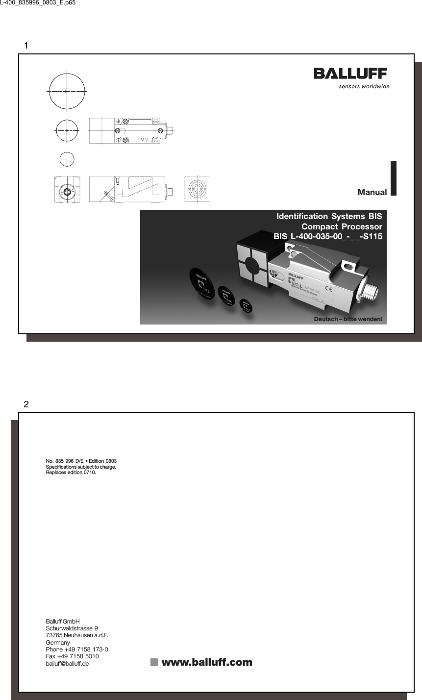
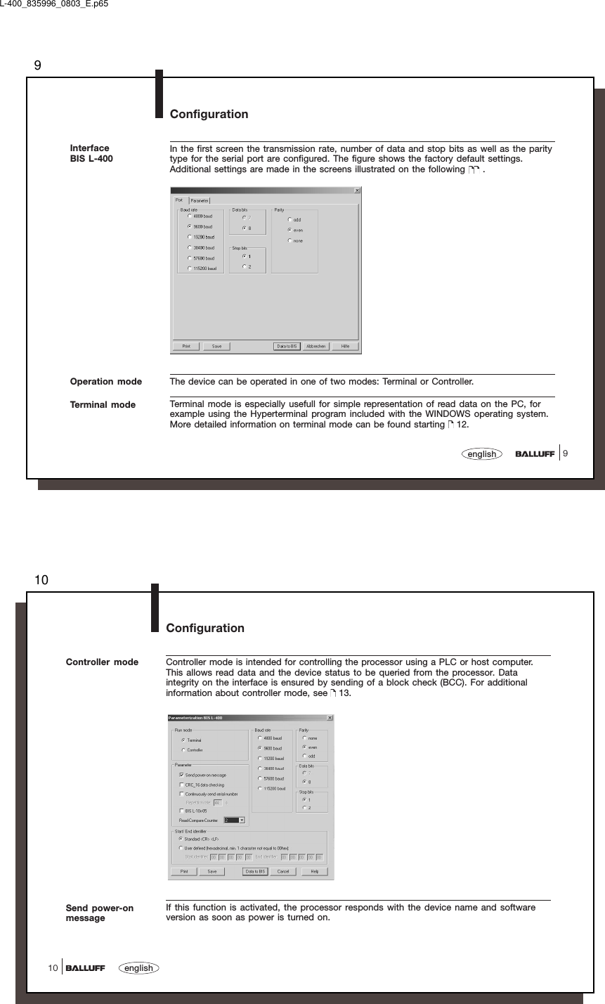
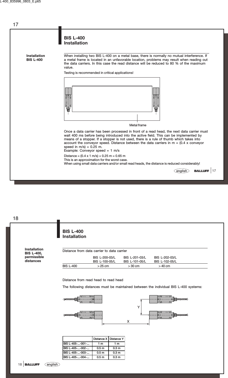
![1919englishBIS L-400-035-001-_ _-S115Installation307.3ø5.340ø1007.35.3 (3x)60461206.540Power T PClear zoneSet screwActive surfaceLData carriers of type BIS L-10_-05 may only be used with the CRC_16 setting or with a serialnumber duplicated by a BIS L-20_-03 data carrier.Characteristic databy data carrier Characteristic databy data carrier(installed in clearzone)at v = 0 (static condition)Readdistance (mm) Center axis offset at adistance of: (mm)0-25 0-35 0-45 0-15BIS L-200-03 /L-100-050 - 30 ± 15 ---BIS L-201-03 /L-101-050 - 40 - ± 20 - -BIS L-202-03 /L-102-050 - 55 - - ± 30 -BIS L-203-03 /L-103-050 - 20 - - - ± 10Speeds (at standard setting datacomparison counter = 2):at readdistance[mm]Speed [m/s]BIS L-200-03 15 0.4BIS L-201-03 20 0.45BIS L-202-03 27.5 0.6BIS L-203-03 10 0.28at readdistance[mm]Speed [m/s]BIS L-100-05 15 0.45BIS L-101-05 20 0.5BIS L-102-05 27.5 0.72BIS L-103-05 10 0.36Speeds (at "BIS L-10_-05" and "CRCdata check"):L-400_835996_0803_E.p6520english20BIS L-400-035-002-_ _-S115InstallationData carriers of type BIS L-10_-05 may only be used with the CRC_16 setting or with a serialnumber duplicated by a BIS L-20_-03 data carrier.Characteristic databy data carrier Characteristic databy data carrier(installed in clearzone)at v = 0 (static condition)Readdistance (mm) Center axis offset at adistance of: (mm)0-10 0-15 0-20 0-25BIS L-200-03 /L-100-050 - 23 ± 12 ± 12 ± 8 -BIS L-201-03 /L-101-050 - 27 ± 15 ± 15 ± 15 ± 6BIS L-203-03 /L-103-050 -16 ± 8 ± 4 - -Active surfaceClear zoneCable length50 cmSet screwCable length max. 20 mat readdistance[mm]Speed [m/s]BIS L-100-05 11.5 0.22BIS L-101-05 13.5 0.3BIS L-103-05 8 0.18at readdistance[mm]Speed [m/s]BIS L-200-03 11.5 0.18BIS L-201-03 13.5 0.22BIS L-203-03 8 0.15Speeds (at standard setting datacomparison counter = 2):Speeds (at "BIS L-10_-05" and "CRCdata check"):](https://usermanual.wiki/Balluff/BISL40000.User-Manual-1-of-2-pdf/User-Guide-2370920-Page-10.png)
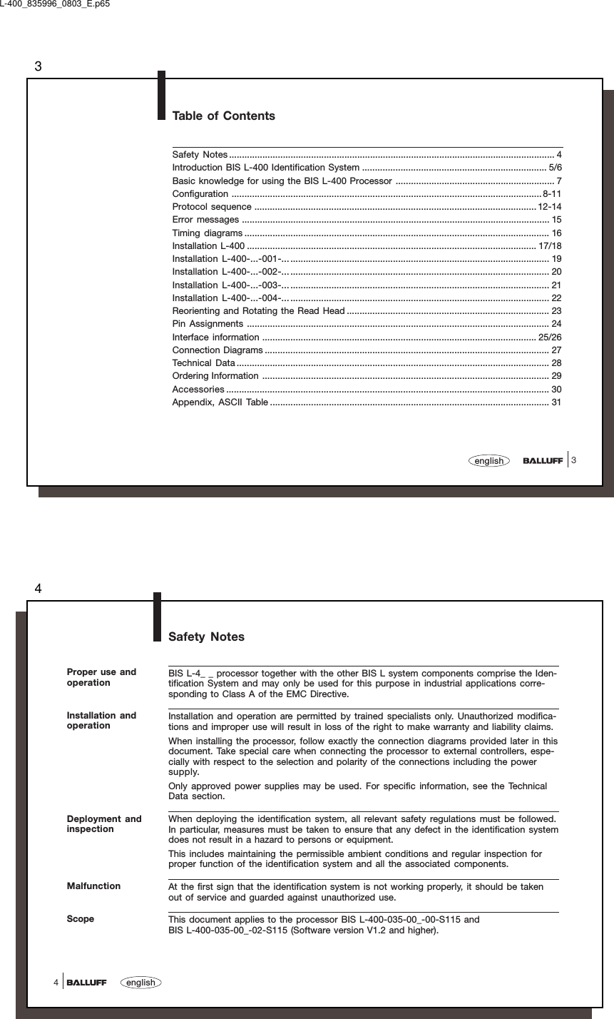
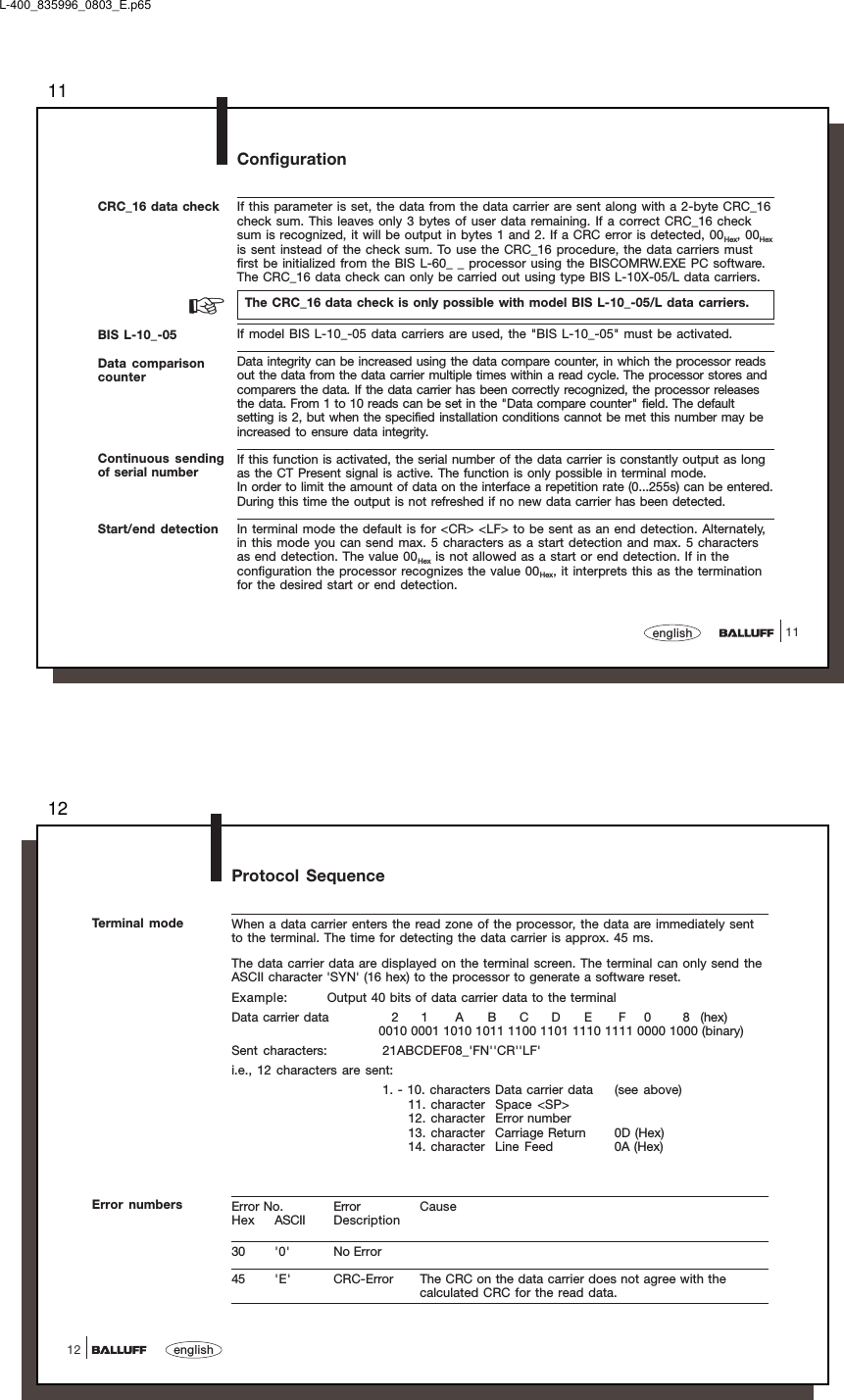
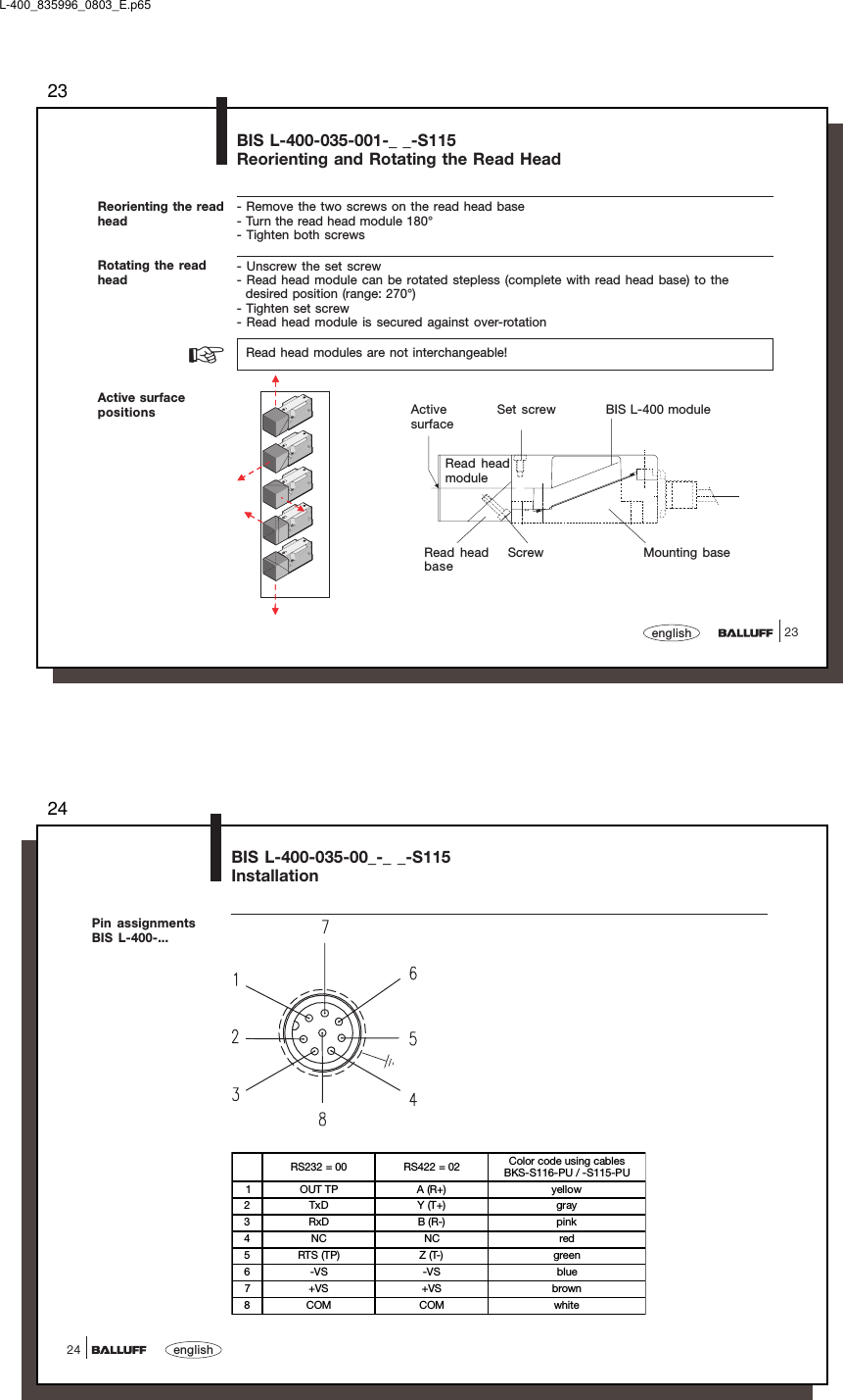
![2121englishData carriers of type BIS L-10_-05 may only be used with the CRC_16 setting or with a serialnumber duplicated by a BIS L-20_-03 data carrier.Characteristic databy data carrier Characteristic databy data carrier(installed in clearzone)at v = 0 (static condition)Readdistance (mm) Center axis offsetat a distance of:(mm)0-5 0-8 0-11BIS L-203-03 /L-103-050 -11 ± 6± 4± 2BIS L-400-035-003-_ _-S115InstallationActive surfaceClear zoneCable length50 cmSet screwCable length max. 20 mat readdistance[mm]Speed [m/s]BIS L-103-05 5.5 0.14at readdistance[mm]Speed [m/s]BIS L-203-03 5.5 0.11Speeds (at standard setting datacomparison counter = 2):Speeds (at "BIS L-10_-05" and "CRCdata check"):L-400_835996_0803_E.p6522english22Data carriers of type BIS L-10_-05 may only be used with the CRC_16 setting or with a serialnumber duplicated by a BIS L-20_-03 data carrier.Characteristic databy data carrier Characteristic databy data carrier(installed in clearzone)at v = 0 (static condition)Readdistance (mm) Center axis offset at adistance of: (mm)0-10 0-15 0-20 0-25BIS L-200-03 /L-100-050 - 23 ± 12 ± 12 ± 8 -BIS L-201-03 /L-101-050 - 27 ± 15 ± 15 ± 15 ± 6BIS L-203-03 /L-103-050 -16 ± 8 ± 4 - -BIS L-400-035-004-_ _-S115InstallationSet screwActive surfaceCable length 50 cmCable length max. 20 mClear zone 50Clear zone 50Clear zone 50at readdistance[mm]Speed [m/s]BIS L-100-05 11.5 0.22BIS L-101-05 13.5 0.3BIS L-103-05 8 0.18at readdistance[mm]Speed [m/s]BIS L-200-03 11.5 0.18BIS L-201-03 13.5 0.22BIS L-203-03 8 0.15Speeds (at standard setting datacomparison counter = 2):Speeds (at "BIS L-10_-05" and "CRCdata check"):](https://usermanual.wiki/Balluff/BISL40000.User-Manual-1-of-2-pdf/User-Guide-2370920-Page-11.png)
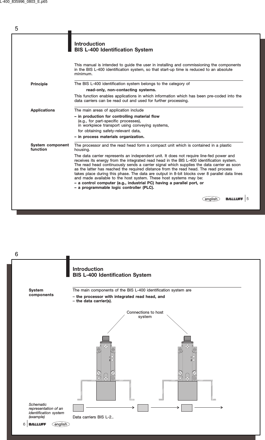
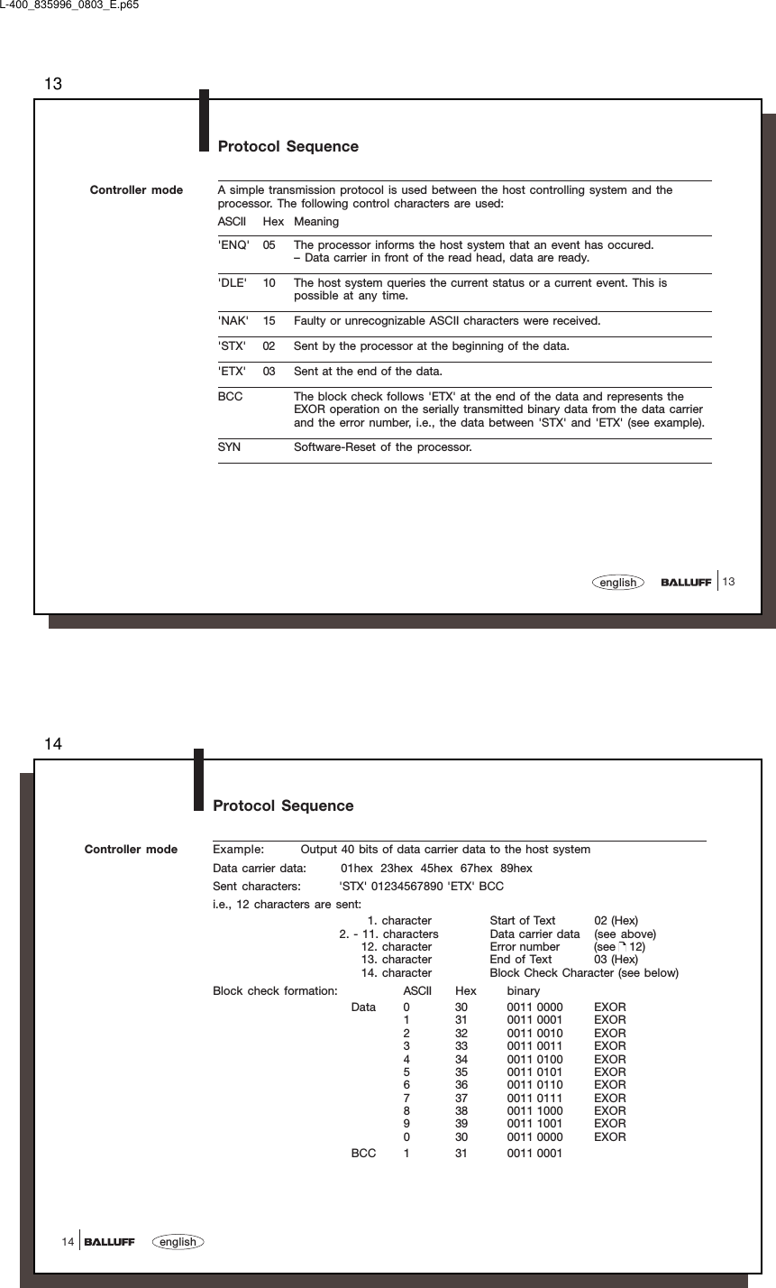
![3131englishAppendix, ASCII TableDeci-mal Hex ControlCode ASCII Deci-mal Hex ControlCode ASCII Deci-mal Hex ASCII Deci-mal Hex ASCII Deci-mal Hex ASCII Deci-mal Hex ASCII0 00 Ctrl @ NUL 22 16 Ctrl V SYN 44 2C , 65 41 A 86 56 V 107 6B k1 01 Ctrl A SOH 23 17 Ctrl W ETB 45 2D - 66 42 B 87 57 W 108 6C l2 02 Ctrl B STX 24 18 Ctrl X CAN 46 2E . 67 43 C 88 58 X 109 6D m3 03 Ctrl C ETX 25 19 Ctrl Y EM 47 2F / 68 44 D 89 59 Y 110 6E n4 04 Ctrl D EOT 26 1A Ctrl Z SUB 48 30 0 69 45 E 90 5A Z 111 6F o5 05 Ctrl E ENQ 27 1B Ctrl [ ESC 49 31 1 70 46 F 91 5B [ 112 70 p6 06 Ctrl F ACK 28 1C Ctrl \ FS 50 32 2 71 47 G 92 5C \ 113 71 q7 07 Ctrl G BEL 29 1D Ctrl ] GS 51 33 3 72 48 H 93 5D ] 114 72 r8 08 Ctrl H BS 30 1E Ctrl ^ RS 52 34 4 73 49 I 94 5E ^ 115 73 s9 09 Ctrl I HT 31 1F Ctrl _ US 53 35 5 74 4A J 95 5F _ 116 74 t10 0A Ctrl J LF 32 20 SP 54 36 6 75 4B K 96 60 ` 117 75 u11 0B Ctrl K VT 33 21 ! 55 37 7 76 4C L 97 61 a 118 76 v12 0C Ctrl L FF 34 22 " 56 38 8 77 4D M 98 62 b 119 77 w13 0D Ctrl M CR 35 23 # 57 39 9 78 4E N 99 63 c 120 78 x14 0E Ctrl N SO 36 24 $ 58 3A : 79 4F O 100 64 d 121 79 y15 0F Ctrl O SI 37 25 % 59 3B ; 80 50 P 101 65 e 122 7A z16 10 Ctrl P DLE 38 26 & 60 3C < 81 51 Q 102 66 f 123 7B {17 11 Ctrl Q DC1 39 27 ' 61 3D = 82 52 R 103 67 g 124 7C |18 12 Ctrl R DC2 40 28 ( 62 3E > 83 53 S 104 68 h 125 7D }19 13 Ctrl S DC3 41 29 ) 63 3F ? 84 54 T 105 69 i 126 7E ~20 14 Ctrl T DC4 42 2A * 64 40 @ 85 55 U 106 6A j 127 7F DEL21 15 Ctrl U NAK 43 2B +L-400_835996_0803_E.p65](https://usermanual.wiki/Balluff/BISL40000.User-Manual-1-of-2-pdf/User-Guide-2370920-Page-16.png)