Balluff COBALT-01 RFID Reader / Writer (HF-CNTL-422-01) User Manual Cobalt Operation Manual
BALLUFF inc RFID Reader / Writer (HF-CNTL-422-01) Cobalt Operation Manual
Balluff >
Contents
- 1. User Manual
- 2. Usr Manual
User Manual


For the Cobalt HF Series of RFID Controllers:
xHF-CNTL-232-01
xHF-CNTL-422-01
xHF-CNTL-485-01
xHF-CNTL-USB-01
xHF-CNTL-IND-01
ESCORT MEMORY SYSTEMS
COBALT HF
RFID CONTROLLERS
High Frequency Passive Radio Frequency Identification Controllers
OPERATOR’SMANUAL
How to Install, Configure and Operate
Escort Memory Systems’
Cobalt HF RFID Controllers
COBALT HF RFID CONTROLLERS OPERATOR’S MANUAL
P/N: 17-1320 REV 01 (03-06) PAGE 3 OF 116
scort Memory Systems reserves the right to make modifications and improvements
to its products and/or documentation without prior notification. Escort Memory
Systems shall not be liable for technical or editorial errors or omissions contained
herein, nor for incidental or consequential damages resulting from the use of this
material.
The text and graphic content contained herein may be used, printed and distributed only
when all of the following conditions are met:
x Permission is first obtained from Escort Memory Systems.
x The content is used for non-commercial purposes only.
x Copyright information is clearly displayed (Copyright © 2006, Escort Memory
Systems, All Rights Reserved).
x The content is not modified.
The following are trademarks and/or registered trademarks of Escort Memory Systems, a
Datalogic Group Company: Escort Memory Systems®, and the Escort Memory Systems
logo, Subnet16™, Cobalt HF™, RFID AT WORK™, C-Macro™, C-MacroBuilder™,
CBx™ and RFID Dashboard™.
Third party product names mentioned herein are used for identification purposes only and
may be trademarks and/or registered trademarks of their respective companies: Philips,
Rockwell Automation (ControlLogix, RSLogix 500) Texas Instruments, Infineon, Modicon,
Belden, Microsoft and the Open DeviceNet Vendor Association (ODVA).
Cobalt HF RFID Controllers - Operator’s Manual
P/N: 17-1320 REV 01 (03-06)
Copyright © 2006 Escort Memory Systems, all rights reserved, published in USA.
E

FCC & CE COMPLIANCE NOTICE
COBALT HF RFID CONTROLLERS OPERATOR’S MANUAL
P/N: 17-1320 REV 01 (03-06) PAGE 4 OF 116
FCC & CE COMPLIANCE NOTICE
FCC PART 15.105
This equipment has been tested and found to comply with the limits for a Class A digital
device, pursuant to part 15 of the FCC Rules. These limits are designed to provide
reasonable protection against harmful interference in a residential installation. This
equipment uses, generates, and can radiate radio frequency energy and, if not installed
and used in accordance with these instructions, may cause harmful interference to radio
communications. However, there is no guarantee that interference will not occur in a
particular installation. If this equipment does cause harmful interference to radio or
television reception, which can be determined by turning the equipment off and on, the
user is encouraged to try to correct the interference by one or more of the following
measures:
x Reorient or relocate the receiving antenna.
x Increase the separation between the equipment and receiver.
x Connect the equipment into an outlet on a circuit different from that to which the
receiver is connected.
x Consult the dealer or an experienced radio/TV technician for help.
FCC PART 15.21
Users are cautioned that changes or modifications to the unit not expressly approved by
Escort Memory Systems may void the user’s authority to operate the equipment.
This device complies with Part 15 of the FCC Rules. Operation is subject to the following
two conditions: (1) This device may not cause harmful interference, and (2) this device
must accept any interference that may cause undesired operation.
This product complies with CFR Title 21 Part 15.225.
CE
This product is compliant to CE requirements and has been tested and complies with EN-
300-330, EN-300-683, EN 60950, IEC 68-2-1, IEC 68-2-6, IEC 68-2-27 and IEC 68-2-28.
TELEC
This product has been certified under:
Regulations for Enforcement of the Radio Law Article 6, section 1, No. 1
Certification #: PENDING

TABLE OF CONTENTS
COBALT HF RFID CONTROLLERS OPERATOR’S MANUAL
P/N: 17-1320 REV 01 (03-06) PAGE 5 OF 116
TABLE OF CONTENTS
FCC & CE COMPLIANCE NOTICE................................................... 4
TABLE OF CONTENTS................................................................... 5
LIST OF TABLES........................................................................... 9
LIST OF FIGURES ....................................................................... 10
CHAPTER 1: GETTING STARTED ............................................... 11
1.1 INTRODUCTION............................................................... 11
1.1.1 Company Background ...............................................................11
1.1.2 About this Manual ....................................................................11
1.2 FEATURES OF THE COBALT CONTROLLER............................. 12
1.3 COBALT CONTROLLER MODELS.......................................... 13
1.3.1 Connections & Communication Interface Options .........................13
1.3.2 Cobalt Controllers - Interface Connectors ...................................14
1.4 CONTROLLER DIMENSIONS................................................ 15
1.4.1 Dimensions for HF-CNTL-232/422-01 Models ..............................15
1.4.2 Dimensions for HF-CNTL-485-01 Model ......................................16
1.4.3 Dimensions for HF-CNTL-USB/IND-01 Models .............................17
1.5 COBALT HF ANTENNAS .................................................... 18
1.5.1 Cobalt HF Antennas – Models and Sizes.....................................18
1.5.2 Antenna to Tag Ranges.............................................................19
1.5.3 Connecting the Antenna to the Controller....................................21
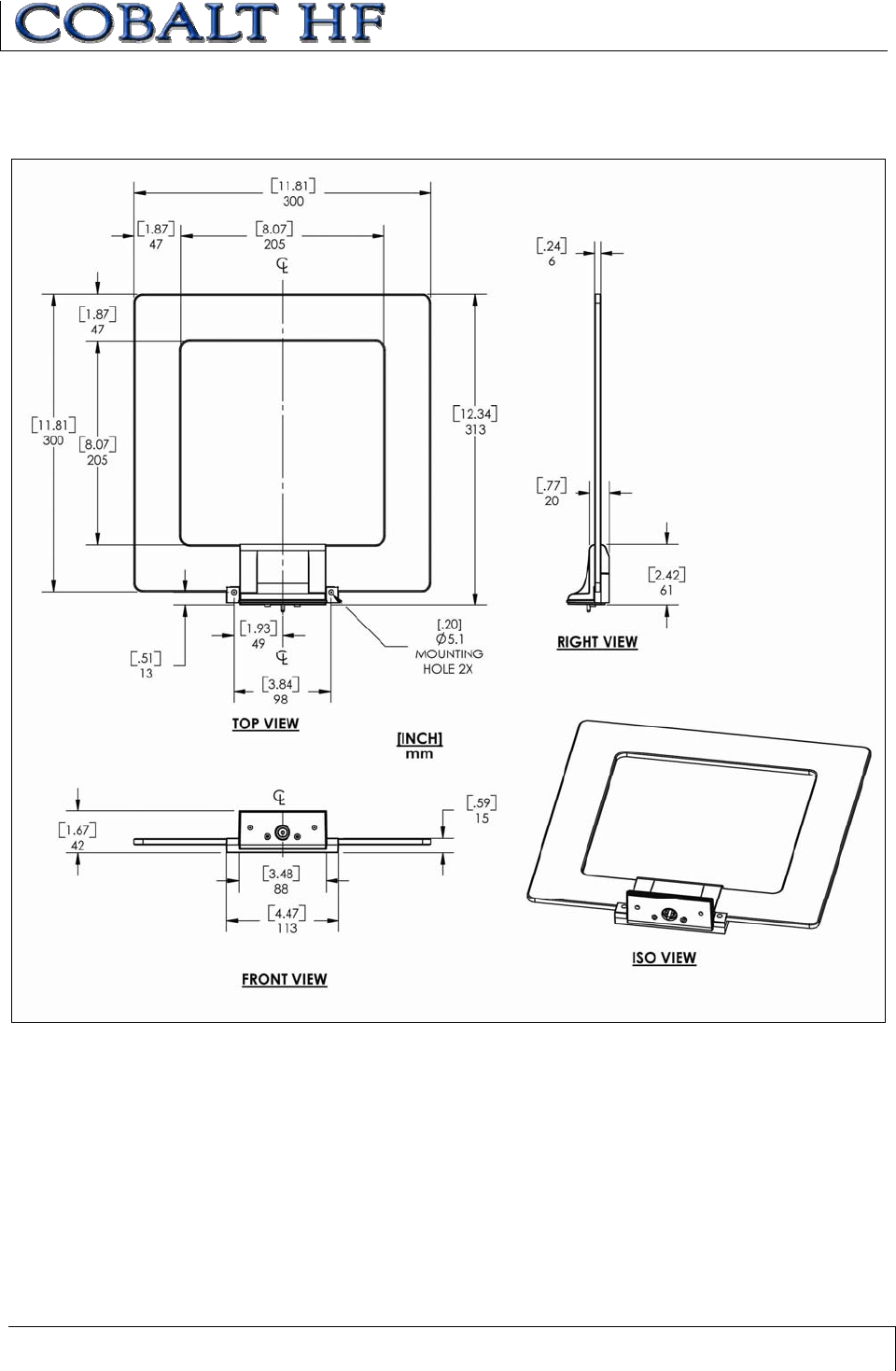
1.6 COBALT HF ANTENNA DIMENSIONS..................................... 22
1.6.1 HF-ANT-1010-01 Antenna Dimensions ........................................22
1.6.2 HF-ANT-2020-01 Antenna Dimensions ........................................23
1.6.3 HF-ANT-3030-01 Antenna Dimensions ........................................24
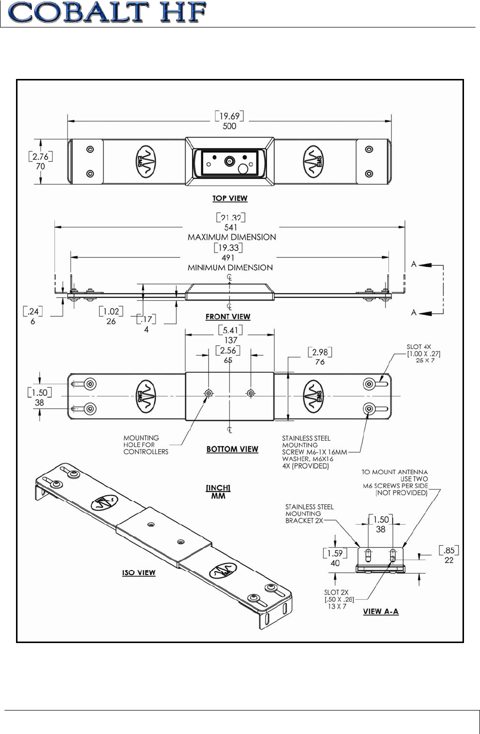
1.6.4 HF-ANT-0750-01 Antenna Dimensions ........................................25
1.7 RFID OVERVIEW ............................................................ 26
1.8 SUBNET16™ MULTIDROP PROTOCOL................................... 28
CHAPTER 2: COBALT INSTALLATION ........................................ 29
2.1 UNPACK &INSPECT THE CONTROLLER ................................ 29
2.1.1 Package Contents ....................................................................29
2.1.2 Providing the Power .................................................................30
2.2 INSTALLATION PRECAUTIONS ............................................ 31

TABLE OF CONTENTS
COBALT HF RFID CONTROLLERS OPERATOR’S MANUAL
P/N: 17-1320 REV 01 (03-06) PAGE 6 OF 116
2.2.1 Installation Guidelines ..............................................................31
2.2.2 Minimum Distance between Antennas .........................................31
2.3 INSTALLING THE HF-CNTL-232-01..................................... 32
2.3.1 HF-CNTL-232-01 Installation .....................................................32
2.3.2 HF-CNTL-232-01 Cabling Information .........................................32
2.4 INSTALLING THE HF-CNTL-422-01..................................... 35
2.4.1 HF-CNTL-422-01 Installation .....................................................35
2.4.2 HF-CNTL-422-01 Cabling Information .........................................35
2.5 INSTALLING THE HF-CNTL-485-01..................................... 38
2.5.1 HF-CNTL-485-01 Installation .....................................................38
2.5.2 HF-CNTL-485-01 Cabling Information .........................................39
2.6 INSTALLING THE HF-CNTL-USB-01.................................... 40
2.6.1 HF-CNTL-USB-01 Installation ....................................................40
2.6.2 HF-CNTL-USB-01 Cabling Information ........................................40
2.7 INSTALLING THE HF-CNTL-IND-01..................................... 42
2.7.1 HF-CNTL-IND-01 Installation .....................................................42
2.7.2 HF-CNTL-IND-01 Cabling Information.........................................43
CHAPTER 3: CONTROLLER CONFIGURATION ............................ 44
3.1 CONFIGURING THE COBALT VIA RFID DASHBOARD ................. 44
3.2 CONFIGURING THE COBALT VIA CONFIGURATION TAG ............. 45
3.2.1 Restoring Factory Default Settings.............................................46
3.2.2 Manually Assigning Node ID (-485 Only).....................................47
3.2.3 Automatic Node Assignment - Subnet16™ Gateway (-485 Only) ...48
3.2.4 Automatic Node Assignment - Subnet16™ Hub (-485 Only)..........48
CHAPTER 4: LED STATUS ......................................................... 49
4.1 LED DESCRIPTIONS ........................................................ 49
4.2 ERROR CONDITIONS ........................................................ 50
CHAPTER 5: RFID TAGS........................................................... 51
5.1 RFID STANDARDS .......................................................... 51
5.1.1 ISO 14443A/B ..........................................................................51
5.1.2 ISO 15693 ...............................................................................52
5.1.3 ISO 18000-3.1 .........................................................................52
5.2 RFID TAG COMPATIBILITY ................................................ 53
5.2.1 HMS Series RFID Tags .............................................................53
5.2.2 LRP Series RFID Tags ..............................................................54
5.3 RFID TAG PERFORMANCE ................................................ 55

TABLE OF CONTENTS
COBALT HF RFID CONTROLLERS OPERATOR’S MANUAL
P/N: 17-1320 REV 01 (03-06) PAGE 7 OF 116
5.4 RFID TAG EMBODIMENTS ................................................. 55
5.4.1 RFID Labels ............................................................................55
5.4.2 Printed Circuit Board RFID Tags ................................................56
5.4.3 Molded RFID Tags....................................................................56
5.5 TAG MEMORY ................................................................ 57
5.5.1 Mapping Tag Memory................................................................57
5.5.2 Tag Memory Optimization..........................................................58
CHAPTER 6: COMMAND PROTOCOLS ........................................ 60
6.1 COMMAND PROTOCOL OVERVIEW ....................................... 60
6.2 ABXFAST COMMAND PROTOCOL........................................ 60
6.2.1 ABx Fast - Command / Response Procedure ...............................60
6.2.2 ABx Fast - Command Packet Structure .......................................61
6.2.3 ABx Fast - Response Packet Structure .......................................62
6.2.4 ABx Fast - Command Packet Parameters ....................................63
6.3 CBXCOMMAND PROTOCOL ............................................... 66
6.3.1 CBx – Command Procedure .......................................................66
6.3.2 CBx – Response Procedure .......................................................66
6.3.3 CBx - Command Packet Structure ..............................................67
6.3.4 CBx - Response Packet Structure ..............................................68
6.3.5 CBx - Command Example ..........................................................69
6.3.6 CBx - Response Example ..........................................................69
CHAPTER 7: RFID COMMANDS .................................................. 70
7.1 RFID COMMANDS TABLE .................................................. 70
COMMAND 04: FILL TAG ....................................................................71
COMMAND 05: READ DATA ................................................................74
COMMAND 06: WRITE DATA ...............................................................77
COMMAND 07: READ TAG ID ..............................................................80
COMMAND 08: TAG SEARCH ..............................................................84
COMMAND 0D: START/STOP CONTINUOUS READ ...............................88
COMMAND 35: RESET CONTROLLER ..................................................95
COMMAND 38: GET CONTROLLER INFO..............................................97
CHAPTER 8: ERROR CODES.................................................... 101
8.1 ERROR CODE TABLE ...................................................... 101
8.2 ABXFAST:ERROR RESPONSE PACKET STRUCTURE ............. 103
8.3 CBXPROTOCOL:ERROR RESPONSE PACKET STRUCTURE ....... 104
APPENDIX A: COBALT HF SPECIFICATIONS............................. 106
APPENDIX B: MODELS & ACCESSORIES .................................. 107

TABLE OF CONTENTS
COBALT HF RFID CONTROLLERS OPERATOR’S MANUAL
P/N: 17-1320 REV 01 (03-06) PAGE 8 OF 116
COBALT HF RFID CONTROLLER MODELS .................................... 107
COBALT HF ANTENNA MODELS................................................. 107
SUBNET16 GATEWAYS ............................................................ 107
SUBNET16 HUBS ...................................................................107
POWER SUPPLIES ..................................................................108
COBALT HF SOFTWARE APPLICATIONS....................................... 108
COBALT CABLES &CONNECTORS.............................................. 109
RFID TAGS .......................................................................... 110
APPENDIX C: NETWORK DIAGRAMS ........................................ 111
APPENDIX D: ASCII CHART...................................................... 114
WARRANTY .............................................................................. 116

LIST OF TABLES
COBALT HF RFID CONTROLLERS OPERATOR’S MANUAL
P/N: 17-1320 REV 01 (03-06) PAGE 9 OF 116
LIST OF TABLES
Table 1-1: Connections & Communication Interface Options ______________________________________13
Table 1-2: Cobalt Controllers - Interface Connectors ____________________________________________14
Table 1-3: Cobalt HF Antennas – Models and Sizes______________________________________________18
Table 1-4: Antenna to Tag Ranges ___________________________________________________________19
Table 1-5: EMS Tag IC and Memory Capacity__________________________________________________20
Table 2-1: Cobalt Controller - Package Contents________________________________________________29
Table 2-2: Minimum Distance between Antennas ________________________________________________31
Table 2-3: HF-CNTL-232-01 Connector Pin Descriptions_________________________________________33
Table 2-4: HF-CNTL-232-01 Default COM Port Settings _________________________________________34
Table 2-5: HF-CNTL-422-01 Connector Pin Descriptions_________________________________________36
Table 2-6: HF-CNTL-422-01 COM Port Default Settings _________________________________________37
Table 2-7: HF-CNTL-485-01 Connector Pin Descriptions_________________________________________39
Table 2-8: HF-CNTL-USB-01 – 5-Pin Female RK Connector: Pin Descriptions _______________________41
Table 2-9: HF-CNTL-USB-01 – 5-Pin Male Connector: Pin Descriptions ____________________________41
Table 2-10: HF-CNTL-IND-01 - 4-Pin Connector: Pin Descriptions ________________________________43
Table 2-11: HF-CNTL-IND-01 - 5-Pin Connector: Pin Descriptions ________________________________43
Table 4-1: Node ID LED Indicator Definitions__________________________________________________49
Table 5-1: Tag Memory Map Example ________________________________________________________58
Table 6-1: ABx Fast - Command Packet Structure _______________________________________________61
Table 6-2: ABx Fast - Response Packet Structure________________________________________________62
Table 6-3: CBx - Command Packet Structure ___________________________________________________67
Table 6-4: CBx - Response Packet Structure ___________________________________________________68
Table 7-1: RFID Commands Table ___________________________________________________________70
Table 7-2: Continuous Read Mode - LED Behavior ______________________________________________89
Table 8-1: Error Code Table_______________________________________________________________102
Table 8-2: ABx Fast - Error Response Structure _______________________________________________103
Table 8-3: CBx Error Response Structure_____________________________________________________104

LIST OF FIGURES
COBALT HF RFID CONTROLLERS OPERATOR’S MANUAL
P/N: 17-1320 REV 01 (03-06) PAGE 10 OF 116
LIST OF FIGURES
Figure 1-1: HF-CNTL-232/422-01 Dimensions _________________________________________________15
Figure 1-2: HF-CNTL-485-01 Dimensions_____________________________________________________16
Figure 1-3: HF-CNTL-USB/IND-01Dimensions_________________________________________________17
Figure 1-4: Controllers with HF-ANT-1010-01, HF-ANT-2020-01 and HF-ANT-3030-01 Antennas _______18
Figure 1-5: HF-ANT-1010-01 Antenna Dimensions ______________________________________________22
Figure 1-6: HF-ANT-2020-01 Antenna Dimensions ______________________________________________23
Figure 1-7: HF-ANT-3030-01 Antenna Dimensions ______________________________________________24
Figure 1-8: HF-ANT-0750-01 Antenna Dimensions ______________________________________________25
Figure 1-9: Industrial Ethernet Subnet16™ Gateway and Hub _____________________________________28
Figure 2-1: HF-CNTL-232-01 – 8-Pin Male M12 Connector_______________________________________32
Figure 2-2: RS232 Interface Cable Schematic __________________________________________________33
Figure 2-3: HF-CNTL-422-01 - 8-Pin Male M12 Connector _______________________________________35
Figure 2-4: RS422 Interface Cable Schematic __________________________________________________36
Figure 2-5: HF-CNTL-485-01 – 5-Pin Male M12 Connector_______________________________________39
Figure 2-6: HF-CNTL-USB-01 - 5-Pin Female M12 Reverse Keyed & 5-Pin Male M12 Connectors________40
Figure 2-7: HF-CNTL-IND-01 - 4-Pin Female M12 D-Code & 5-Pin Male M12 Connectors _____________43
Figure 3-1: RFID Dashboard Utility _________________________________________________________44
Figure 3-2: Cobalt Controller Set to Node ID 01 ________________________________________________47
Figure 5-1: HMS125HT and HMS150HT RFID Tags ____________________________________________53
Figure 5-2: LRP125 and LRP250 RFID Tags___________________________________________________54

CHAPTER 1: GETTING STARTED
COBALT HF RFID CONTROLLERS OPERATOR’S MANUAL
P/N: 17-1320 REV 01 (03-06) PAGE 11 OF 116
CHAPTER 1:
GETTING STARTED
1.1 INTRODUCTION
Welcome to the Cobalt HF RFID Controllers - Operator’s Manual. This manual will
assist you in the installation, configuration and operation of the Cobalt HF RFID
Controllers.
The Cobalt HF family is a complete line of feature-rich, passive high frequency read/write
Radio-Frequency Identification devices that provide RFID data collection and control
solutions to shop floor, item-level tracking and material handling applications. They are
designed to be compact, rugged and reliable, in order to meet and exceed the
requirements of the industrial automation industry.
1.1.1 Company Background
Escort Memory Systems has long been an industry leader in providing Radio Frequency
Identification devices and has built a solid reputation by consistently delivering an
extended selection of quality, durable industrial grade RFID products.
1.1.2 About this Manual
This manual provides guidelines and instructions for installing and operating the Cobalt
HF RFID Controller. Included are descriptions of the RFID command set and examples
demonstrating how to issue commands to the Cobalt HF RFID Controller.
Numbers expressed in Hexadecimal notation, are prefaced with “0x”. For example, the
number ten in decimal is expressed as 0x0A in hexadecimal. See Appendix D for a chart
containing Hex values up to 0x7F, their corresponding ASCII characters and decimal
integer equivalents.

CHAPTER 1: GETTING STARTED
COBALT HF RFID CONTROLLERS OPERATOR’S MANUAL
P/N: 17-1320 REV 01 (03-06) PAGE 12 OF 116
1.2 FEATURES OF THE COBALT CONTROLLER
x High performance, industrial, multi-protocol RFID controller
x Supports communication interface protocols: Subnet16™, Commercial TCP/IP,
Ethernet/IP™ and Modbus® TCP
x Interface Options: RS232, RS422, RS485, USB and Ethernet
x Reads/Writes ISO 14443A, ISO 15693 and Philips® I•CODE® 1 tag ICs and
compliant RFID tags
x Compatible with HMS-Series and LRP-Series RFID tags from Escort Memory
Systems
x Supports Escort Memory Systems’ ABx Fast & CBx™ command protocols
x Internationally recognized ISM frequency of 13.56 MHz.
x Rugged IP66 rated housing
x 8 LED status indicators for power, COM Activity, RF Activity, Subnet16 Node ID,
system diagnostics and error codes
x Flash memory for software upgrades
x Auto configurable and software programmable
x Unique serial ID number on every controller
x FCC/CE/TELEC agency compliance certification
CHAPTER 1: GETTING STARTED
COBALT HF RFID CONTROLLERS OPERATOR’S MANUAL
P/N: 17-1320 REV 01 (03-06) PAGE 13 OF 116
1.3 COBALT CONTROLLER MODELS
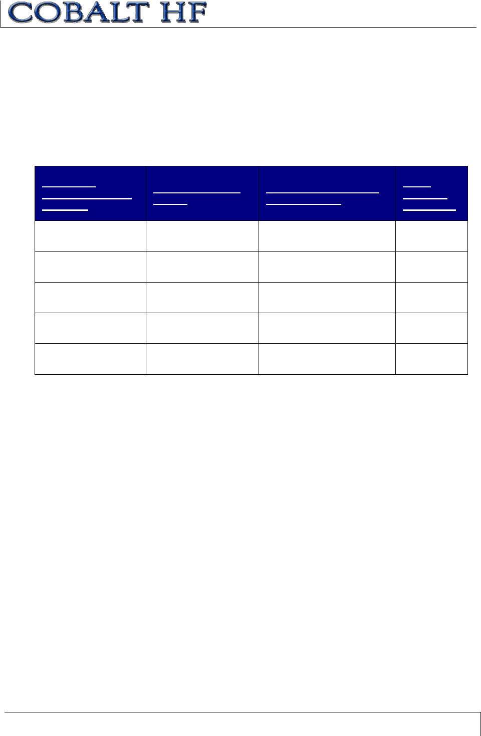
There are five models of the Cobalt HF RFID Controller. Each model is designed to
support a specific communication interface option. The table below lists the five controller
models, their respective connection types and communication interfaces.
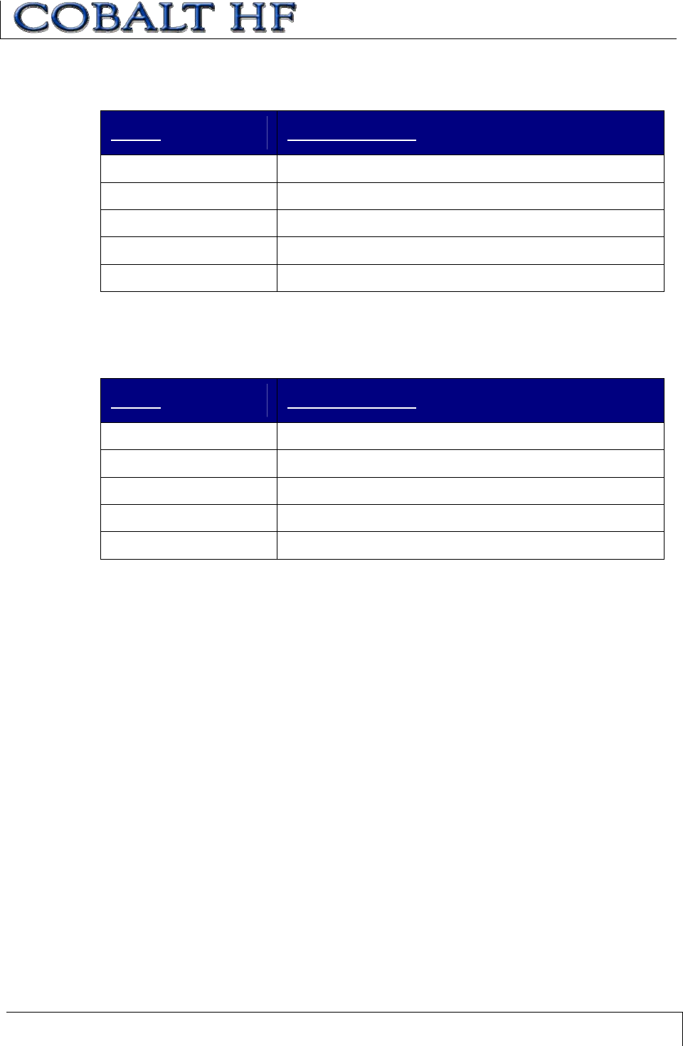
1.3.1 Connections & Communication Interface Options
COBALT
CONTROLLER
MODEL
CONNECTION
TYPE
COMMUNICATION
INTERFACE
MAX
CABLE
LENGTH
HF-CNTL-232-01 RS232 Point-to-Point,
Host/Controller 15m
HF-CNTL-422-01 RS422 Point-to-Point,
Host/Controller 300m
HF-CNTL-485-01 RS485 Multidrop (Subnet16) Bus
Architecture 300m
HF-CNTL-USB-01 USB Point-to-Point,
Host/Controller 3m
HF-CNTL-IND-01 Ethernet TCP/IP, Ethernet/IP,
Modbus TCP 100m
Table 1-1: Connections & Communication Interface Options
CHAPTER 1: GETTING STARTED
COBALT HF RFID CONTROLLERS OPERATOR’S MANUAL
P/N: 17-1320 REV 01 (03-06) PAGE 14 OF 116
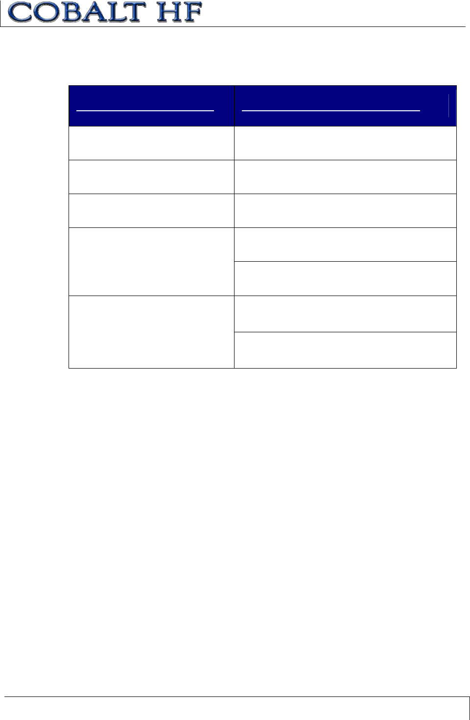
1.3.2 Cobalt Controllers - Interface Connectors
CONTROLLER MODEL INTERFACE CONNECTOR(S)
HF-CNTL-232-01 8-pin Male M12 connector for power and data
HF-CNTL-422-01 8-pin Male M12 connector for power and data
HF-CNTL-485-01 5-pin Male M12 connector for power and data
5-pin Male M12 connector for power
HF-CNTL-USB-01
(2 connectors) 5-pin Female M12 reverse keyed connector for
data
5-pin Male M12 connector for power
HF-CNTL-IND-01
(2 connectors) 4-pin Female M12 D-Code connector for data
Table 1-2: Cobalt Controllers - Interface Connectors
CHAPTER 1: GETTING STARTED
COBALT HF RFID CONTROLLERS OPERATOR’S MANUAL
P/N: 17-1320 REV 01 (03-06) PAGE 15 OF 116
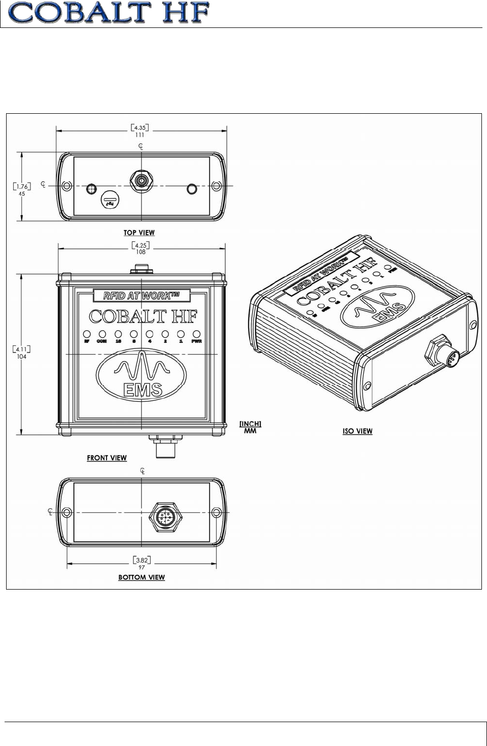
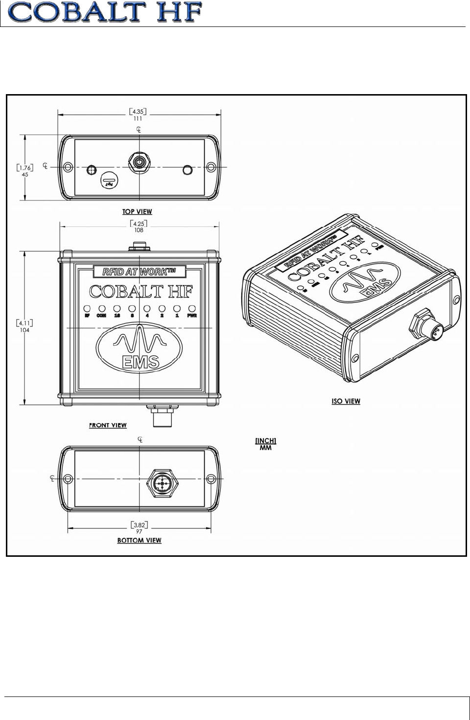
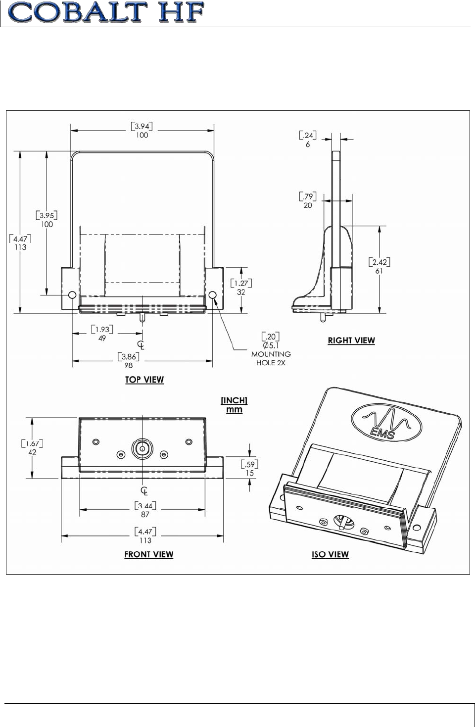
1.4 CONTROLLER DIMENSIONS
1.4.1 Dimensions for HF-CNTL-232/422-01 Models
Figure 1-1: HF-CNTL-232/422-01 Dimensions
CHAPTER 1: GETTING STARTED
COBALT HF RFID CONTROLLERS OPERATOR’S MANUAL
P/N: 17-1320 REV 01 (03-06) PAGE 16 OF 116
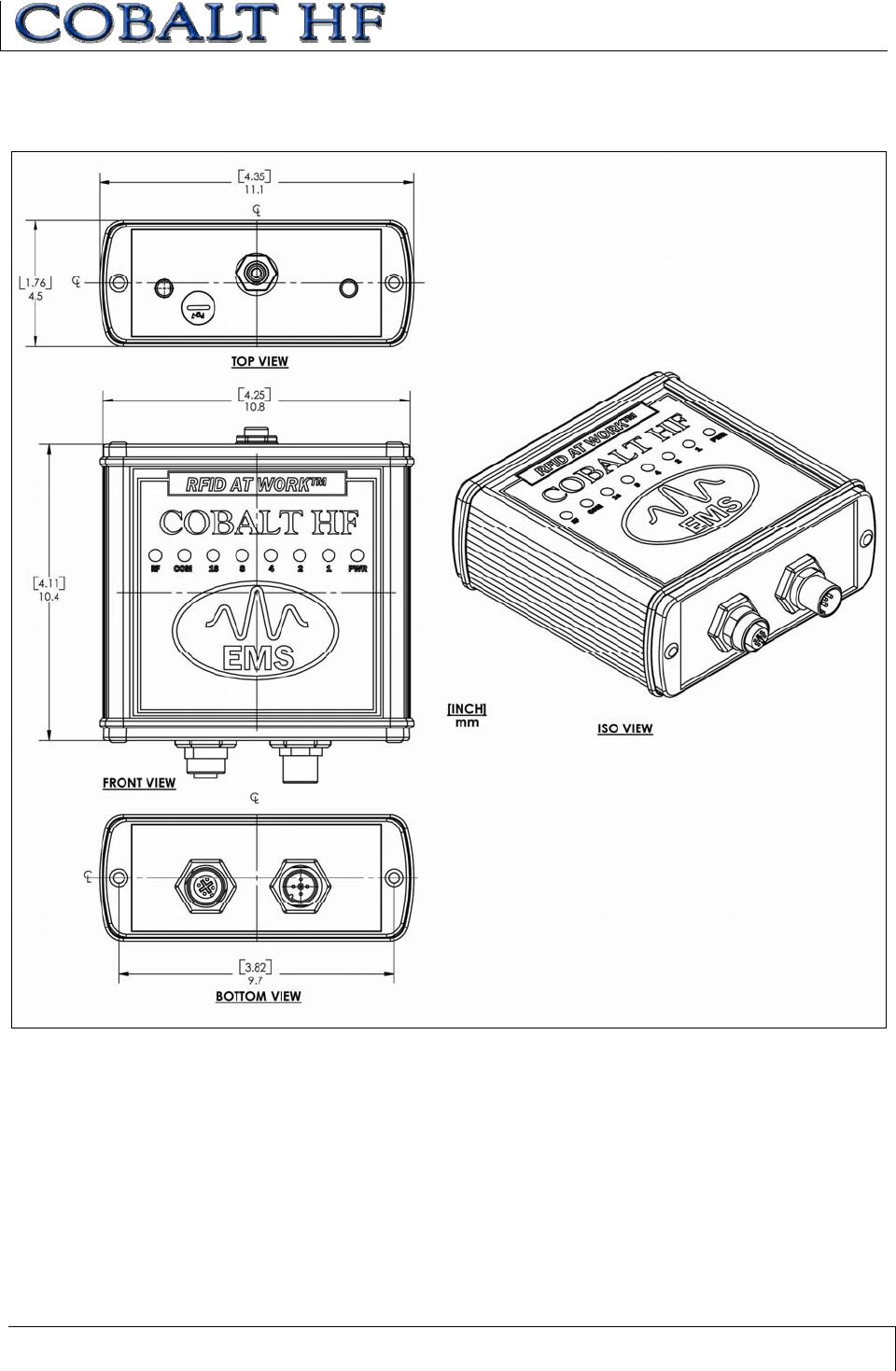
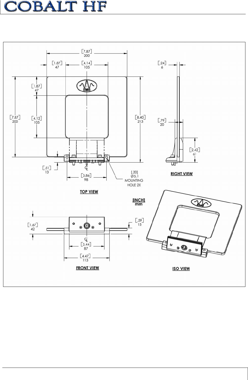
1.4.2 Dimensions for HF-CNTL-485-01 Model
Figure 1-2: HF-CNTL-485-01 Dimensions
CHAPTER 1: GETTING STARTED
COBALT HF RFID CONTROLLERS OPERATOR’S MANUAL
P/N: 17-1320 REV 01 (03-06) PAGE 17 OF 116
1.4.3 Dimensions for HF-CNTL-USB/IND-01 Models
Figure 1-3: HF-CNTL-USB/IND-01Dimensions
CHAPTER 1: GETTING STARTED
COBALT HF RFID CONTROLLERS OPERATOR’S MANUAL
P/N: 17-1320 REV 01 (03-06) PAGE 18 OF 116
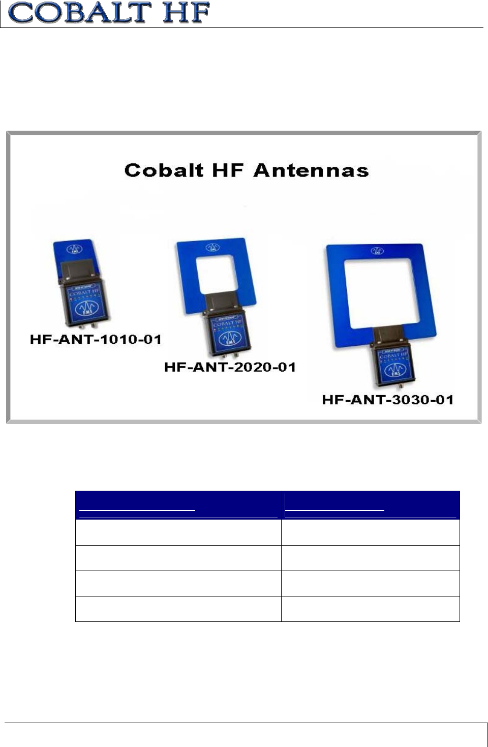
1.5 COBALT HF ANTENNAS
The Cobalt HF family currently includes four different RFID antennas (three of which are
pictured below). Because the Cobalt Antennas are designed with different dimensions,
they each generate a different size RF field and read/write range.
Figure 1-4: Controllers with HF-ANT-1010-01, HF-ANT-2020-01 and HF-ANT-3030-01 Antennas
1.5.1 Cobalt HF Antennas – Models and Sizes
ANTENNA MODEL ANTENNA SIZE
HF-ANT-1010-01 10cm x 10cm
HF-ANT-2020-01 20cm x 20cm
HF-ANT-3030-01 30cm x 30cm
HF-ANT-0750-01 7cm x 50cm
Table 1-3: Cobalt HF Antennas – Models and Sizes
CHAPTER 1: GETTING STARTED
COBALT HF RFID CONTROLLERS OPERATOR’S MANUAL
P/N: 17-1320 REV 01 (03-06) PAGE 19 OF 116
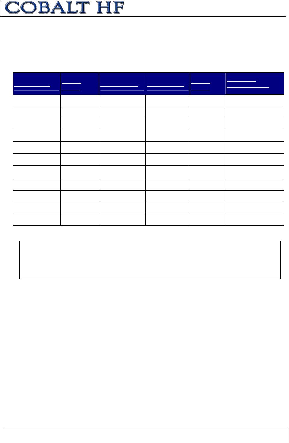
1.5.2 Antenna to Tag Ranges
COBALT ANTENNA TO TAG RANGE TABLE
Tag range values are listed in millimeters and inches (mm / in.).
EMS TAG ANT-
1010 ANT-2020 ANT-3030 ANT-
0750
TESTING
ENVIRONMENT
LRP125(HT) 152 / 6.0 203 / 8.0 228 / 9.0 Pending Free Air
LRP125(HT)S 152 / 6.0 216 / 8.5 228 / 9.0 Pending Free Air
LRP250(HT) 178 / 7.0 267 / 10.5 305 / 12.0 Pending Free Air
LRP250(HT)S 267 / 10.5 381 / 15.0 406 / 16.0 Pending Free Air
LRP-P3858 216 / 8.5 292 / 11.5 343 / 13.5 Pending Free Air
LRP-P3858S 216 / 8.5 292 / 11.5 343 / 13.5 Pending Free Air
HMS125(HT) 64 / 2.5 64 / 2.5 Not Advised Pending Free Air
HMS-P138 127 / 5.0 178 / 7.0 178 / 7.0 Pending Free Air
HMS150(HT) 127 / 5.0 183 / 7.2 165 / 6.5 Pending Free Air
LRP525HTS 254 / 10.0 381 / 15.0 432 / 17.0 Pending Attached to Metal
LRP525S 216 / 8.5 318 / 12.5 356 / 14.0 Pending Attached to Metal
Table 1-4: Antenna to Tag Ranges
ATTENTION
The tag range values listed above are provided for design purposes. Range can be adversely
affected by many environmental factors including metal, moisture and liquids. Testing should
be performed in the actual environment for more precise range results.
See table below for tag ICs and memory capacities.
CHAPTER 1: GETTING STARTED
COBALT HF RFID CONTROLLERS OPERATOR’S MANUAL
P/N: 17-1320 REV 01 (03-06) PAGE 20 OF 116
EMS TAG IC AND MEMORY CAPACITY
The following table lists the integrated circuit (IC) and memory size of each Escort
Memory Systems’ LRP and HMS-Series RFID tag included in the Antenna to Tag Range
table above.
EMS TAG TAG IC MEMORY SIZE
LRP125(HT) I•CODE 1 48-bytes + 8-byte ID
LRP125(HT)S I•CODE 2 (SLi) 112-bytes + 8-byte ID
LRP250(HT) I•CODE 1 48-bytes + 8-byte ID
LRP250(HT)S I•CODE 2 (SLi) 112-bytes + 8-byte ID
LRP525(HT)S I•CODE 2 (SLi) 112-bytes + 8-byte ID
LRP525S I•CODE 2 (SLi) 112-bytes + 8-byte ID
LRP-P3858 I•CODE 1 48-bytes + 8-byte ID
LRP-P3858S I•CODE 2 (SLi) 112-bytes + 8-byte ID
HMS125(HT) Mifare Classic 736-bytes + 4-byte ID
HMS-P138 Mifare Classic 736-bytes + 4-byte ID
HMS150(HT) Mifare Classic 736-bytes + 4-byte ID
Table 1-5: EMS Tag IC and Memory Capacity
CHAPTER 1: GETTING STARTED
COBALT HF RFID CONTROLLERS OPERATOR’S MANUAL
P/N: 17-1320 REV 01 (03-06) PAGE 21 OF 116
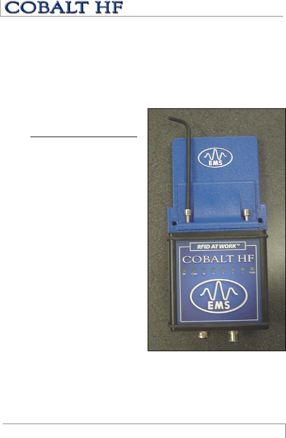
1.5.3 Connecting the Antenna to the Controller
Cobalt HF Antennas mount directly to the top of the Cobalt HF RFID Controller’s housing.
The antenna is first attached to the RF port on the controller and is then fastened to the
controller’s housing with the two M5 screws and matching lock washers included with
each Cobalt HF RFID Controller. Carefully use the provided 4mm hex key wrench to
tighten both M5 screws per the torque specification below:
ANTENNA MOUNTING TORQUE SPECIFICATION
Torque Specification for the two M5
screws that hold the antenna to the
controller:
1.7 Nm or 15 lbs per inch ± 10%
CHAPTER 1: GETTING STARTED
COBALT HF RFID CONTROLLERS OPERATOR’S MANUAL
P/N: 17-1320 REV 01 (03-06) PAGE 22 OF 116
1.6 COBALT HF ANTENNA DIMENSIONS
1.6.1 HF-ANT-1010-01 Antenna Dimensions
Figure 1-5: HF-ANT-1010-01 Antenna Dimensions
CHAPTER 1: GETTING STARTED
COBALT HF RFID CONTROLLERS OPERATOR’S MANUAL
P/N: 17-1320 REV 01 (03-06) PAGE 23 OF 116
1.6.2 HF-ANT-2020-01 Antenna Dimensions
Figure 1-6: HF-ANT-2020-01 Antenna Dimensions
CHAPTER 1: GETTING STARTED
COBALT HF RFID CONTROLLERS OPERATOR’S MANUAL
P/N: 17-1320 REV 01 (03-06) PAGE 24 OF 116
1.6.3 HF-ANT-3030-01 Antenna Dimensions
Figure 1-7: HF-ANT-3030-01 Antenna Dimensions
CHAPTER 1: GETTING STARTED
COBALT HF RFID CONTROLLERS OPERATOR’S MANUAL
P/N: 17-1320 REV 01 (03-06) PAGE 25 OF 116
1.6.4 HF-ANT-0750-01 Antenna Dimensions
Figure 1-8: HF-ANT-0750-01 Antenna Dimensions

CHAPTER 1: GETTING STARTED
COBALT HF RFID CONTROLLERS OPERATOR’S MANUAL
P/N: 17-1320 REV 01 (03-06) PAGE 26 OF 116
1.7 RFID OVERVIEW
The Cobalt HF-series products are designed for use with passive RFID tags. Passive
tags require no batteries and are energized by the magnetic field of the Cobalt HF
controller’s antenna. Through inductive coupling, power is induced from the controller’s
antenna into the antenna of the RFID tag. Similar to a transformer, the efficiency of the
energy transferred is a result of the size and number of turns on the transmit antenna
(primary winding) and size and number of turns on the tag’s antenna (secondary
winding). The resonant frequency of each antenna coil and its Q-factor (quality factor)
are primary design concerns for efficient antenna coil and tag coil designs.
Optimum tuned coils for both the antenna and tag will achieve the best energy transfer.
The Q-factor defines how wide of bandwidth the energy is spread over. The RF output
power is fixed within the legal limits, the higher the peak energy at the resonant
frequency the higher the Q value and the narrower the bandwidth. Inversely, the lower
the peak energy at the resonant frequency the lower the Q value and the wider the
bandwidth. Higher the Q values of the two antenna coils will produce the greatest range.
However the with too high a Q value the less tolerant the system will be of shifts of the
resonant frequency. The lower the Q value, the wider the bandwidth and the greater
tolerance the system will have to shifting of the resonant frequency.
Tuned antenna circuits are affected by virtually all materials, whether they are metal,
water, plastic, cement or even the human touch. Some materials will shift the resonant
frequency up, and other materials will shift the frequency down and some have more
affect than others. Metal and water will have the most serious affect on antenna tuning,
metal more so than water. The lower the frequency the less affect metal and water have
on the performance. The 13.56MHz HF frequency provides the best compromise
between range, speed, and immunity to environmental affects. The HF-series products
are designed with optimum antenna designs with Q values required for most applications.
The Cobalt HF-series operates at the ISM (Industrial, Scientific, Medical) internationally
accepted frequency of 13.56MHz. 13.56MHz is considered to be in the High Frequency
spectrum as opposed to 864MHz or 915MHz which fall under the Ultra-High Frequency
or UHF spectrum, or 2.4GHz in the microwave range spectrum. For reference,
13.56MHz falls between the AM and FM radio bands.
Understanding these principals is important when considering the mounting of the HF
Controller’s antenna and the RFID tag. Unless the tag or antenna is designed specifically
for mounting close to metal, non-metallic mounting brackets and non-metallic tag spacers
are required to achieve optimum read and write ranges.
Electrical noise generated by motors, conveyors and other automation equipment can
produce excessive electrical noise which can negatively affect the RF communications.
The Cobalt HF series products should only be used on well grounded systems.
Conveyors systems should be tied directly to earth ground by an electrician. All cables
used on and around the RFID system must be shielded cables. Cable shields should
typically be grounded at both ends, however, differences in ground potentials can
produce “ground loops” and in those cases the ground connection may need to be lifted
at one end of the cable.
The range performance specified in this and other Escort Memory Systems publications
refer to the free air measurement, meaning there is no metal in the field. Because the
proximity to metal and other environmental conditions affect read and write range, it is
impossible for Escort Memory Systems to state the absolute range that will be achieved

CHAPTER 1: GETTING STARTED
COBALT HF RFID CONTROLLERS OPERATOR’S MANUAL
P/N: 17-1320 REV 01 (03-06) PAGE 27 OF 116
in for all conditions. The system integrator must validate the performance as the
products are to be used and can not rely solely on the published range specifications.
The Cobalt HF RFID Controller is compatible with Escort Memory Systems LRP and
HMS series RFID tags. HMS series tags are referred to as proximity whereas the LRP
series are referred to as vicinity tags and have longer range. HMS tags utilize ISO
14443A integrated circuits while the LRP series utilize Philips ICODE1 and ISO15693
integrated circuits manufactured by Phillips, Fujitsu, and Infineon. The Cobalt HF-series
is also capable of reading other ISO15693 compliant tags.
For more information on RFID tags, see Chapter 5: RFID Tags.
CHAPTER 1: GETTING STARTED
COBALT HF RFID CONTROLLERS OPERATOR’S MANUAL
P/N: 17-1320 REV 01 (03-06) PAGE 28 OF 116
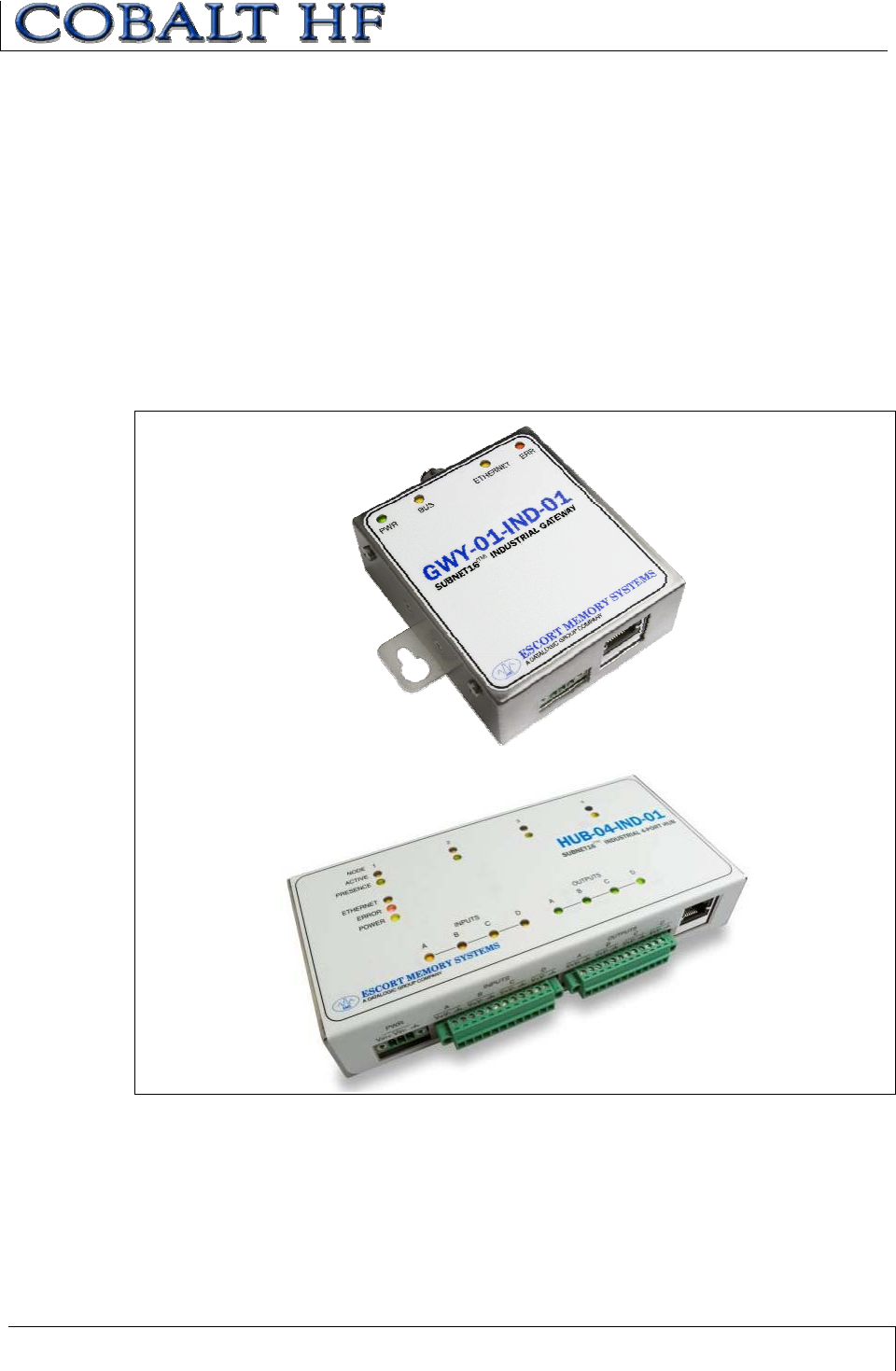
1.8 SUBNET16™ MULTIDROP PROTOCOL
The HF-CNTL-485-01 model includes support for Escort Memory Systems’ Subnet16™
Multidrop RFID networking protocol. Under the Subnet16 protocol, up to 16 HF-CNTL-
485-01 RFID Controllers can be connected via a trunk and tap network to an Industrial
Ethernet Subnet16™ Gateway (GWY-01-IND-01) or TCP/IP Subnet16™ Gateway
(GWY-01-TCP-01) interface module.
HF-CNTL-485-01 models can also be connected directly to an Industrial Ethernet
Subnet16™ Hub (HUB-04-IND-01) or TCP/IP Subnet16™ Hub (HUB-04-TCP-01)
interface module. The Subnet16™ Hubs have four independent controller ports, four
digital inputs and four digital outputs.
Figure 1-9: Industrial Ethernet Subnet16™ Gateway and Hub
CHAPTER 2: COBALT INSTALLATION
COBALT HF RFID CONTROLLERS OPERATOR’S MANUAL
P/N: 17-1320 REV 01 (03-06) PAGE 29 OF 116
CHAPTER 2:
COBALT INSTALLATION
2.1 UNPACK &INSPECT THE CONTROLLER
Unpack the Cobalt Controller hardware and accessories. Retain the original shipping
carton and packing material in case an item needs to be returned. Inspect each piece
carefully, if an item appears to be damaged, notify your Escort Memory Systems product
distributor.
2.1.1 Package Contents
The Cobalt HF RFID Controller product package contains the following components:
PART
NUMBER QUANTITY DESCRIPTION
HF-CNTL-XXX-01 1 Cobalt HF Series RFID Controller
17-312X1 HF-CNTL-XXX-01 - Installation Guide
20-1950 2Antenna Mounting Screws (M5 x 20mm,
Hex #4, Stainless Steel)
20-3915 2Spring Washers for Antenna Mounting
Screws (M5, Stainless Steel)
69-1289 1 Tool - Hex #4 (4mm L-Key)
00-3000 1 Cobalt HF Series - Configuration Tag
CBL-1487 1
Field Mountable 5-Pin Female M12
Connector for Power Connection (USB and
IND Models).
XXX = Model Designation (232, 422, 485, USB or IND)
Table 2-1: Cobalt Controller - Package Contents

CHAPTER 2: COBALT INSTALLATION
COBALT HF RFID CONTROLLERS OPERATOR’S MANUAL
P/N: 17-1320 REV 01 (03-06) PAGE 30 OF 116
2.1.2 Providing the Power
Cobalt Controllers require an electrical supply voltage of 10~30VDC and have a power
consumption of 12W (450mA @ 24VDC).
Employ a regulated power supply that is capable of delivering these requirements. Below
is a list of power supplies available from Escort Memory Systems.
COBALT HF RFID CONTROLLERS -POWER SUPPLY PART NUMBERS
x00-1166: (24VDC, 1.88A max, 45W)
x00-1167: (24VDC, 4.17A max, 100W)
x00-1168: (24VDC, 5.0A max, 120W)
CHAPTER 2: COBALT INSTALLATION
COBALT HF RFID CONTROLLERS OPERATOR’S MANUAL
P/N: 17-1320 REV 01 (03-06) PAGE 31 OF 116
2.2 INSTALLATION PRECAUTIONS
RF performance and read/write range can be negatively impacted by the proximity of
metallic objects. Avoid mounting the antenna within 15cm (6 inches) of any metallic
object or surface.
2.2.1 Installation Guidelines
x Do not route cables near unshielded cables or near wiring carrying high voltage
or high current. Cross cables at perpendicular intersections and avoid routing
cables near motors and solenoids.
x Avoid mounting the Cobalt Controller near sources of EMI (electro-magnetic
interference) or near devices that generate high ESD (electro-static discharge)
levels.
x In the event that electrical interference is encountered (as indicated by a
reduction in read/write performance) try relocating the controller to an area away
from the potential source of interference.
x Plan to perform a test phase where you will construct a small scale, independent
network that includes only the essential devices required to test your RFID
application. To avoid possible interference with other devices, avoid connecting
your RFID testing environment to an existing local area network.
x The Cobalt HF Controller is designed to withstand 8kV of direct electro-static
discharge (ESD) and 15kV of air gap discharge. However, it is not uncommon for
some conveyor applications to generate considerably higher ESD levels. Use
adequate ESD prevention measures to dissipate potentially high voltages.
2.2.2 Minimum Distance between Antennas
When using multiple Cobalt HF Controllers/Antennas, maintain the recommended
minimum distance between adjacent Cobalt Antennas (see table below).
COBALT
ANTENNA 1010 2020 3030 0750
1010 60cm 75cm 90cm 50cm
2020 75cm 90cm 1.2m 65cm
3030 90cm 1.2m 2m 90cm
0750 50cm 65cm 90cm 50cm
Table 2-2: Minimum Distance between Antennas
CHAPTER 2: COBALT INSTALLATION
COBALT HF RFID CONTROLLERS OPERATOR’S MANUAL
P/N: 17-1320 REV 01 (03-06) PAGE 32 OF 116
2.3 INSTALLING THE HF-CNTL-232-01
2.3.1 HF-CNTL-232-01 Installation
1. Attach the Cobalt HF Antenna to the Cobalt HF Controller (refer to Section 1.5.3).
2. Following the guidelines in Section 2.2.1, select a suitable location for the Cobalt
HF Controller/Antenna. If necessary, fabricate mounting brackets from durable
plastic.
3. Fasten the combined controller and antenna to the mounting fixture using two M5
(#10) diameter screws, each passing through the antenna’s mounting holes and
secured with locking washers and nuts. Tighten screws to 1.7 Nm or 15 lbs per
inch ± 10%.
4. Connect the 8-pin female M12 end of a serial communications cable to the 8-pin
male M12 connector on the Cobalt HF-CNTL-232-01.
5. Connect the opposite end of this cable to an available COM port on the host
computer (see Section 2.3.2, below, for cabling information).
6. Provide a power supply for the controller that is capable of delivering 10~30VDC,
12W.
7. Turn the power supply ON. The green power LED and the yellow Node ID 1 LED
will remain lit. The Node ID 1 LED indicates that the controller is in RS232 mode.
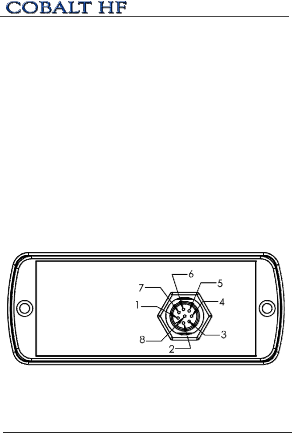
2.3.2 HF-CNTL-232-01 Cabling Information
Figure 2-1: HF-CNTL-232-01 – 8-Pin Male M12 Connector
CHAPTER 2: COBALT INSTALLATION
COBALT HF RFID CONTROLLERS OPERATOR’S MANUAL
P/N: 17-1320 REV 01 (03-06) PAGE 33 OF 116
HF-CNTL-232-01 CONNECTOR PIN DESCRIPTIONS
PIN # DESCRIPTION
110~30VDC PWR
20VDC (POWER GND)
3NOT CONNECTED
4NOT CONNECTED
5NOT CONNECTED
6RX
7TX
8SGND (SIGNAL GROUND)
Table 2-3: HF-CNTL-232-01 Connector Pin Descriptions
RS232 INTERFACE CABLE SCHEMATIC
Figure 2-2: RS232 Interface Cable Schematic
CHAPTER 2: COBALT INSTALLATION
COBALT HF RFID CONTROLLERS OPERATOR’S MANUAL
P/N: 17-1320 REV 01 (03-06) PAGE 34 OF 116
HF-CNTL-232-01 DEFAULT COM PORT SETTINGS
COM PORT PARAMETER DEFAULT SETTING
Baud 9600*
Data Bits 8
Stop Bits 1
Parity None
Handshaking None
Table 2-4: HF-CNTL-232-01 Default COM Port Settings
*The Cobalt HF-CNTL-232-01 supports baud rates of 9600, 19.2k, 38.4k, 57.6k and
115.2k.
HF-CNTL-232-01 CABLING PART NUMBERS
xCBL-1478: (RS232 Cable, Female, DB9, 2.5mm DC Jack).
xCBL-1488-XX: (8-pin, Female M12 w/ Bare Wires).
xCBL-1491: (8-pin, Female M12 Right Angle Field Mountable Connector).
xCBL-1492-XX: (8-pin, Female M12 Right Angle, Bare Wires).
xCBL-1493: (8-pin, Female M12 Straight Field Mountable Connector).
x Recommended Bulk RS232 cable - Belden P/N: 9941.
(XX = Cable Length in Meters)
CHAPTER 2: COBALT INSTALLATION
COBALT HF RFID CONTROLLERS OPERATOR’S MANUAL
P/N: 17-1320 REV 01 (03-06) PAGE 35 OF 116
2.4 INSTALLING THE HF-CNTL-422-01
2.4.1 HF-CNTL-422-01 Installation
1. Attach the Cobalt HF Antenna to the Cobalt HF Controller (refer to Section 1.5.3).
2. Following the guidelines in Section 2.2.1, select a suitable location for the Cobalt
HF Controller/Antenna. Fabricate mounting brackets from durable plastic, if
necessary.
3. Fasten the combined controller and antenna to the mounting fixture using two M5
(#10) diameter screws, each passing through the antenna’s mounting holes and
secured with locking washers and nuts. Tighten screws to 1.7 Nm or 15 lbs per
inch ± 10%.
4. Connect the 8-pin female M12 connector from a serial communications cable to
the 8-pin male M12 connector on the Cobalt HF RFID Controller (refer to Section
2.4.2 below for cabling information).
5. Attach the other end of the serial cable to the RS422 port on the host PC. Follow
wiring instructions included with the host RS422 interface.
6. Provide a regulated power supply of 10~30VDC, 12W for the controller.
7. Turn the power supply ON. The green power LED and the yellow Node ID 2 LED
will remain ON while power is applied to the unit. The Node ID 2 LED indicates
that the controller is in RS422 mode.
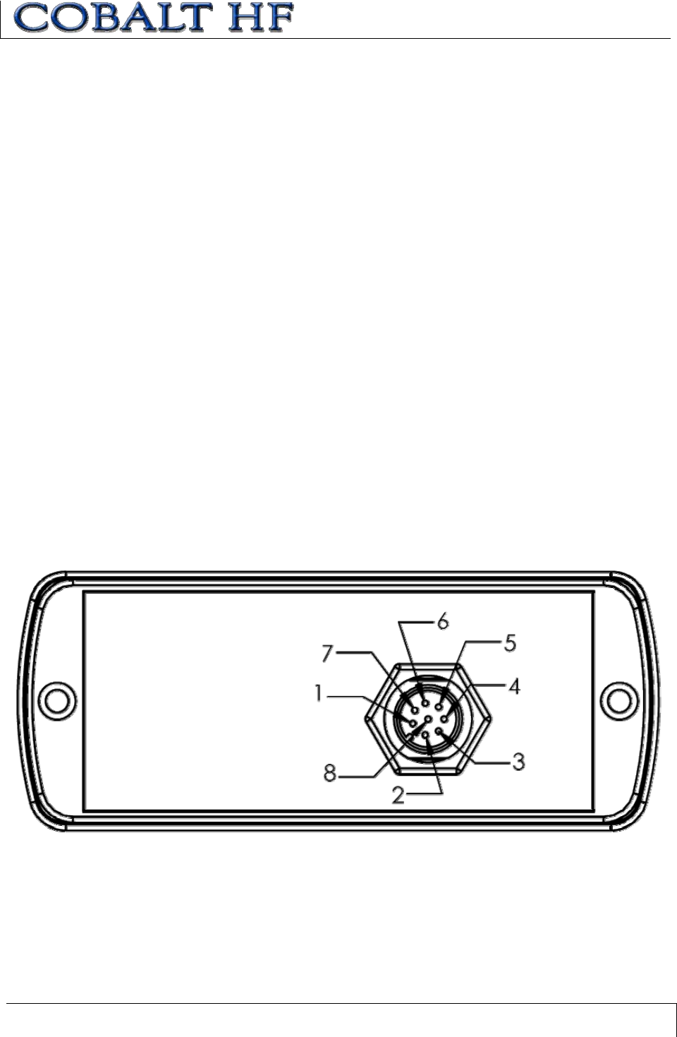
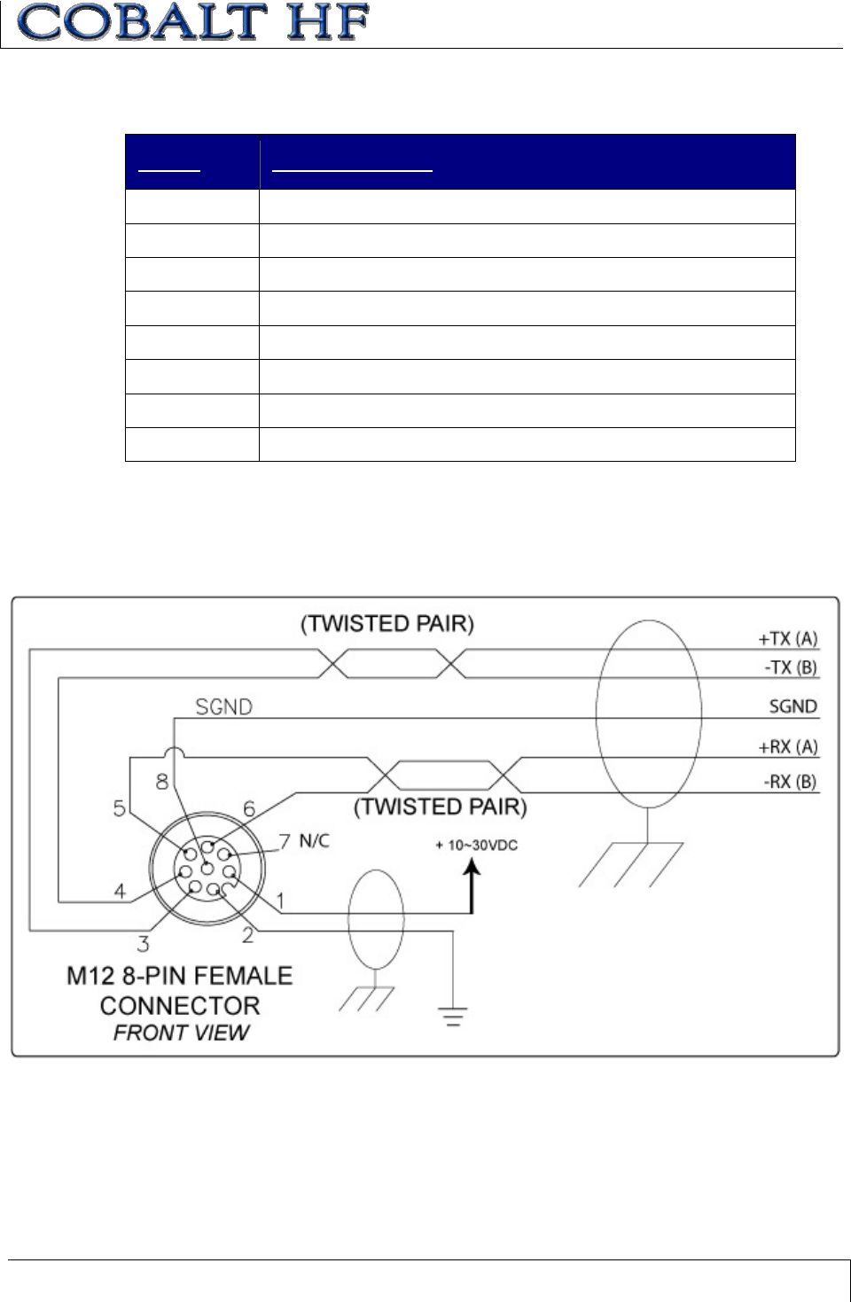
2.4.2 HF-CNTL-422-01 Cabling Information
Figure 2-3: HF-CNTL-422-01 - 8-Pin Male M12 Connector
CHAPTER 2: COBALT INSTALLATION
COBALT HF RFID CONTROLLERS OPERATOR’S MANUAL
P/N: 17-1320 REV 01 (03-06) PAGE 36 OF 116
HF-CNTL-422-01 CONNECTOR PIN DESCRIPTIONS
PIN # DESCRIPTION
110~30VDC PWR
20VDC (POWER GND)
3+TX (A)
4-TX (B)
5+RX (A)
6-RX (B)
7NOT CONNECTED
8SGND (SIGNAL GND)
Table 2-5: HF-CNTL-422-01 Connector Pin Descriptions
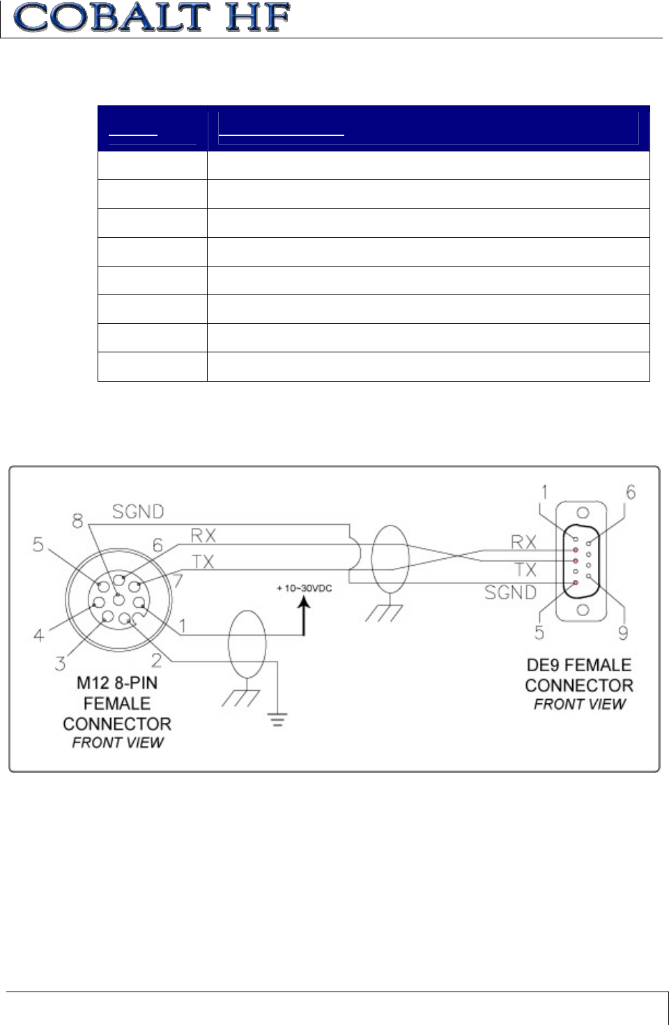
RS422 INTERFACE CABLE SCHEMATIC
Figure 2-4: RS422 Interface Cable Schematic

CHAPTER 2: COBALT INSTALLATION
COBALT HF RFID CONTROLLERS OPERATOR’S MANUAL
P/N: 17-1320 REV 01 (03-06) PAGE 37 OF 116
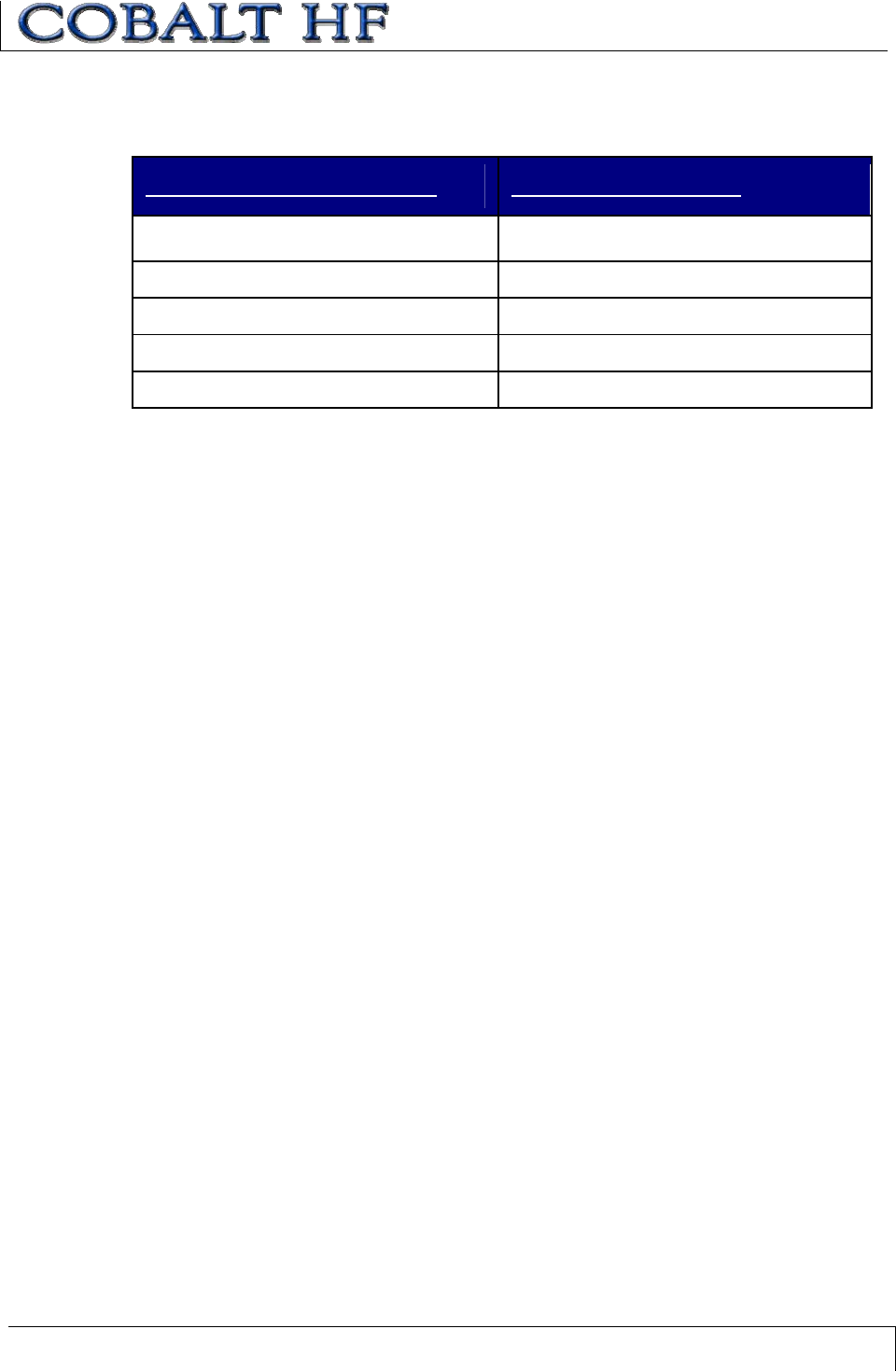
HF-CNTL-422-01 COM PORT DEFAULT SETTINGS
COM PORT PARAMETER DEFAULT SETTING
Baud 9600*
Data Bits 8
Stop Bits 1
Parity None
Handshaking None
Table 2-6: HF-CNTL-422-01 COM Port Default Settings
*The Cobalt HF-CNTL-422-01 supports baud rates of 9600, 19.2k, 38.4k, 57.6k and
115.2k.
HF-CNTL-422-01 CABLING PART NUMBERS
xCBL-1491: (8-pin, Female, M12 Right Angle Field Mountable Connector)
xCBL-1493: (8-pin, Female, M12 Straight Field Mountable Connector)

CHAPTER 2: COBALT INSTALLATION
COBALT HF RFID CONTROLLERS OPERATOR’S MANUAL
P/N: 17-1320 REV 01 (03-06) PAGE 38 OF 116
2.5 INSTALLING THE HF-CNTL-485-01
2.5.1 HF-CNTL-485-01 Installation
1. Attach the Cobalt HF Antenna to the Cobalt HF Controller (refer to Section 1.5.3).
2. Following the guidelines in Section 2.2.1, select a suitable location for the Cobalt
HF Controller/Antenna. Fabricate mounting brackets from a durable plastic if
necessary.
3. Fasten the combined controller and antenna to the mounting fixture using two M5
(#10) diameter screws, each passing through the antenna’s mounting holes and
secured with locking washers and nuts. Tighten screws to 1.7 Nm or 15 lbs per
inch ± 10%.
4. Follow the installation instructions from the Subnet16 Gateway or Subnet16 Hub
Operator’s Manual. Connect the 5-pin female end of a Subnet cable to the
controller’s 5-pin male M12 connector. Use only Escort Memory Systems
Subnet16 approved cables. (See Appendix B for a complete list of cabling
accessories).
5. Provide a regulated power supply of 10~30VDC, 12W for the controller.
6. Turn the power supply ON. The green power LED on the unit will illuminate when
power is applied to the unit. The yellow Node ID LEDs, when lit, display the
Subnet16 Node ID (in binary) that is currently assigned to the controller. Note:
the default Node ID is Node 00; in which case none of the yellow Node ID LEDs
will be lit.
Note: the Gateway and Hub Operator’s Manuals are available online at www.ems-
rfid.com.
CHAPTER 2: COBALT INSTALLATION
COBALT HF RFID CONTROLLERS OPERATOR’S MANUAL
P/N: 17-1320 REV 01 (03-06) PAGE 39 OF 116
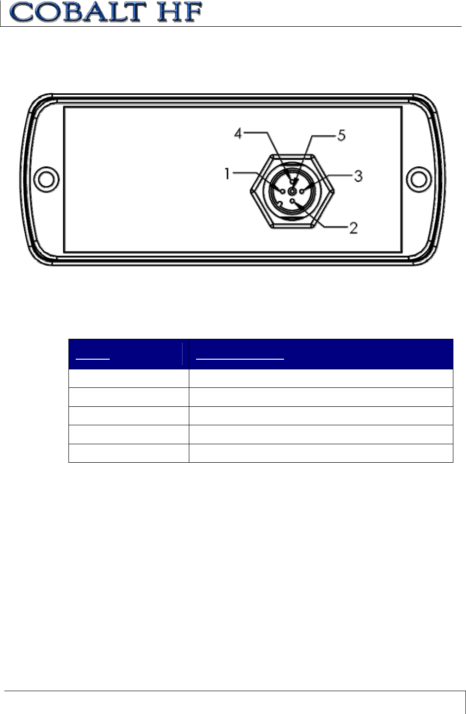
2.5.2 HF-CNTL-485-01 Cabling Information
Figure 2-5: HF-CNTL-485-01 – 5-Pin Male M12 Connector
HF-CNTL-485-01 CONNECTOR PIN DESCRIPTIONS
PIN # DESCRIPTION
1SIGNAL GND
210~30VDC PWR
30V (POWER GND)
4TX/RX+
5TX/RX-
Table 2-7: HF-CNTL-485-01 Connector Pin Descriptions
CHAPTER 2: COBALT INSTALLATION
COBALT HF RFID CONTROLLERS OPERATOR’S MANUAL
P/N: 17-1320 REV 01 (03-06) PAGE 40 OF 116
2.6 INSTALLING THE HF-CNTL-USB-01
2.6.1 HF-CNTL-USB-01 Installation
1. Attach the Cobalt HF Antenna to the Cobalt HF Controller (refer to Section 1.5.3).
2. Following the guidelines in Section 2.2.1, select a suitable location for the Cobalt
HF Controller/Antenna. Fabricate mounting brackets from a durable plastic if
necessary.
3. Fasten the combined controller and antenna to the mounting fixture using two M5
(#10) diameter screws, each passing through the antenna’s mounting holes and
secured with locking washers and nuts. Tighten screws to 1.7 Nm or 15 lbs per
inch ± 10%.
4. Download the Cobalt HF USB driver from the Escort Memory Systems Web site
(www.ems-rfid.com). Follow instructions provided with the download to install the
USB driver. Do not connect the USB cable at this time.
5. Provide a power supply: 10~30VDC, 12W.
6. Attach the 5-pin female M12 connector from a power supply cable to the 5-pin
male M12 connector on the Cobalt Controller.
7. Connect the 5-pin male M12 reverse keyed connector end of the Cobalt HF USB
Cable (CBL-1513) to the 5-pin female M12 connector on the Cobalt Controller.
Do not plug the USB cable into the PC yet.
8. Turn the power supply ON. The green power LED and the yellow LED 4 will
remain ON while power is applied to the unit. The LED 4 light indicates that the
controller is in USB mode.
9. After the USB drivers are installed and the Cobalt HF Controller completes its
boot cycle, plug the remaining end of the USB cable into a USB port on the host
PC.
2.6.2 HF-CNTL-USB-01 Cabling Information
Figure 2-6: HF-CNTL-USB-01 - 5-Pin Female M12 Reverse Keyed & 5-Pin Male M12 Connectors
CHAPTER 2: COBALT INSTALLATION
COBALT HF RFID CONTROLLERS OPERATOR’S MANUAL
P/N: 17-1320 REV 01 (03-06) PAGE 41 OF 116
HF-CNTL-USB-01 – 5-PIN FEMALE RK CONNECTOR:PIN DESCRIPTIONS
PIN # DESCRIPTION
1+5V
2D-
3D+
4GND
5SHIELD
Table 2-8: HF-CNTL-USB-01 – 5-Pin Female RK Connector: Pin Descriptions
HF-CNTL-USB-01 – 5-PIN MALE CONNECTOR:PIN DESCRIPTIONS
PIN # DESCRIPTION
1SHIELD GND
210~30VDC PWR
30V (POWER GND)
4NOT CONNECTED
5NOT CONNECTED
Table 2-9: HF-CNTL-USB-01 – 5-Pin Male Connector: Pin Descriptions
HF-CNTL-USB-01 CABLING PART NUMBERS
xCBL-1513: (Cable, 5-Pin Male M12, USB, 3M)
xCBL-1514: (USB Connector for HF-CNTL-USB-01)
CHAPTER 2: COBALT INSTALLATION
COBALT HF RFID CONTROLLERS OPERATOR’S MANUAL
P/N: 17-1320 REV 01 (03-06) PAGE 42 OF 116
2.7 INSTALLING THE HF-CNTL-IND-01
2.7.1 HF-CNTL-IND-01 Installation
1. Attach the Cobalt HF Antenna to the Cobalt HF Controller (refer to Section 1.5.3).
2. Following the guidelines in Section 2.2.1, select a suitable location for the Cobalt
HF Controller/Antenna. Fabricate mounting brackets from a durable plastic if
necessary.
3. Fasten the combined controller and antenna to the mounting fixture using two M5
(#10) diameter screws, each passing through the antenna’s mounting holes and
secured with lock washers and nuts. Tighten screws to 1.7 Nm or 15 lbs per inch
± 10%.
4. Attach the 5-pin female M12 connector end from a power supply cable to the 5-
pin male M12 connector on the Cobalt Controller. The other end of this cable
should connect to a regulated power supply capable of delivering 10~30VDC,
12W.
5. Attach the 4-pin male M12 D-Code connector from a CAT 5E (or better) industrial
Ethernet cable (CBL-1515-XX) to the 4-pin female D-Code connector on the
Cobalt Controller.
6. Connect the other end of the Subnet16 compatible communications cable to an
RJ45 interface adapter. Attach the other end from the RJ45 interface adapter to
an available Ethernet port on the host PC.
7. Turn the power supply ON. The green power LED on the unit will illuminate. The
yellow Node ID 8 LED will be lit when the controller is using its default IP
address. The yellow Node ID 16 LED will be lit when the controller is operating
with a user defined IP address.
HF-CNTL-IND-01 DEFAULT IP ADDRESS
192.168.253.110
CHAPTER 2: COBALT INSTALLATION
COBALT HF RFID CONTROLLERS OPERATOR’S MANUAL
P/N: 17-1320 REV 01 (03-06) PAGE 43 OF 116
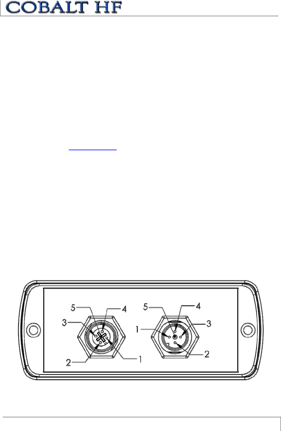
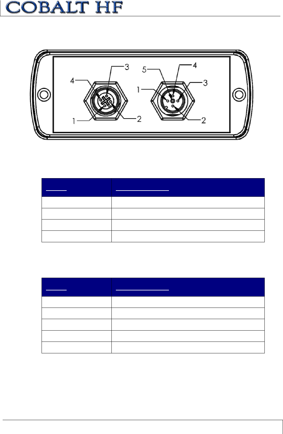
2.7.2 HF-CNTL-IND-01 Cabling Information
Figure 2-7: HF-CNTL-IND-01 - 4-Pin Female M12 D-Code & 5-Pin Male M12 Connectors
HF-CNTL-IND-01 – 4-PIN CONNECTOR:PIN DESCRIPTIONS
PIN # DESCRIPTION
1+ TX
2+ RX
3- TX
4- RX
Table 2-10: HF-CNTL-IND-01 - 4-Pin Connector: Pin Descriptions
HF-CNTL-IND-01 – 5-PIN CONNECTOR:PIN DESCRIPTIONS
PIN # DESCRIPTION
1SHIELD GND
210~30VDC PWR
30V (POWER GND)
4NOT CONNECTED
5NOT CONNECTED
Table 2-11: HF-CNTL-IND-01 - 5-Pin Connector: Pin Descriptions
HF-CNTL-IND-01 -C
ABLING PART NUMBERS
xCBL-1487: (Connector, Straight Female, M12, 5-Pin, Field Mountable)
xCBL-1515-05: (Cable, 5M, Ethernet/M12, 5-Pin, Male, D-Code)
CHAPTER 3:
CONTROLLER CONFIGURATION
COBALT HF RFID CONTROLLERS OPERATOR’S MANUAL
P/N: 17-1320 REV 01 (03-06) PAGE 44 OF 116
CHAPTER 3:
CONTROLLER CONFIGURATION
Stored in the Cobalt’s flash memory is a group of settings and parameters known as the
“Controller Configuration.” These parameters indicate, for example, the Command
Protocol in use, the Tag IC to recognize and the software version currently installed.
The Controller Configuration can be modified by using Escort Memory Systems’ RFID
Dashboard™ utility or through the use of an HF-Series Configuration Tag (included
with the Cobalt Controller).
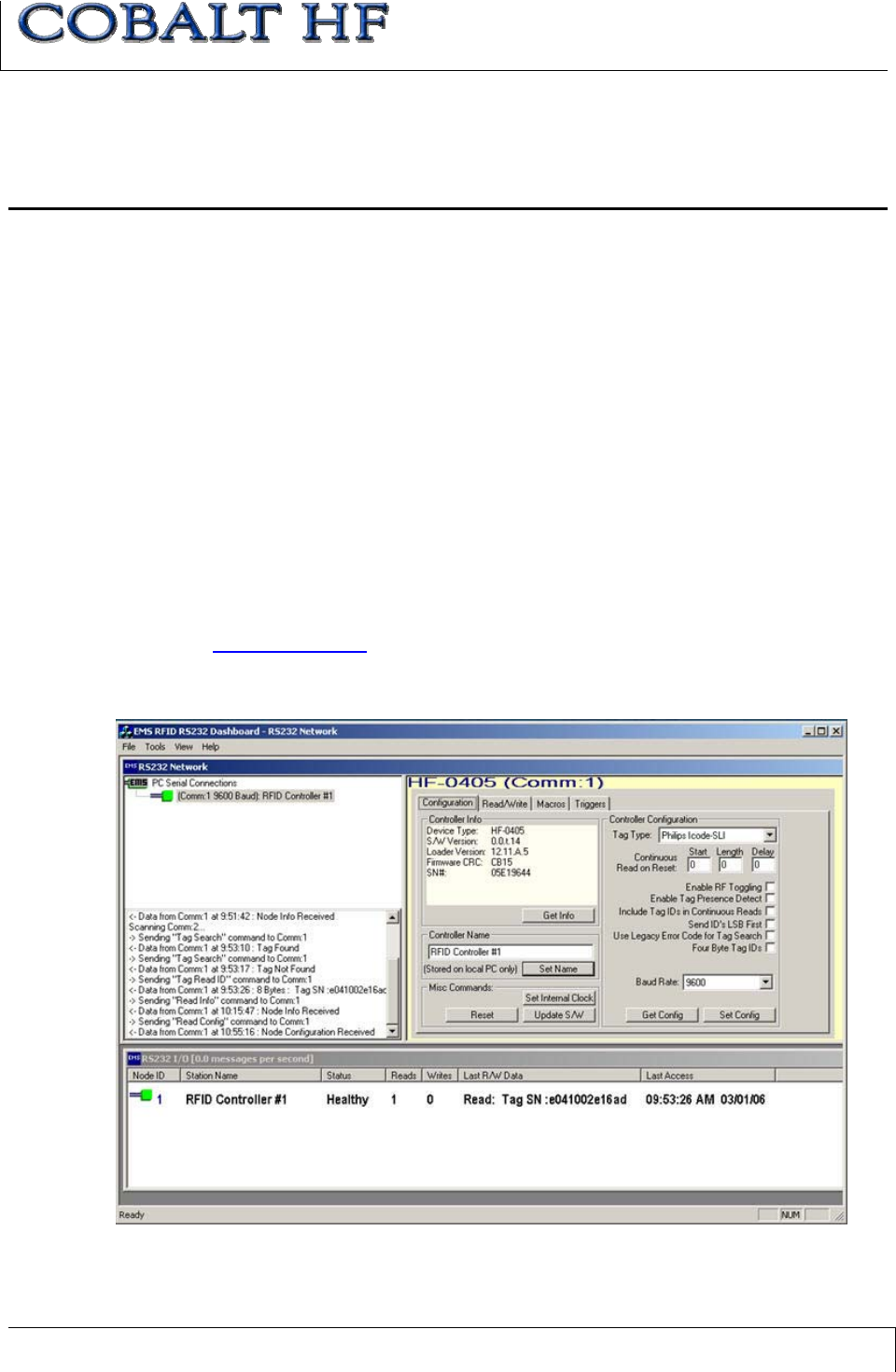
3.1 CONFIGURING THE COBALT VIA RFID
DASHBOARD
The RFID Dashboard utility is a software application that allows users to view, modify,
save and update the configuration settings of their Cobalt Controllers.
Note: there are two versions of the RFID Dashboard: one for serial connections
(-232, -422, -USB) and one for TCP/IP connections (-485, -IND).
x Download the appropriate version of the RFID Dashboard from
www.ems-rfid.com.
x Follow the instructions included with the software to install the RFID Dashboard
and set the Cobalt Controller’s configuration.
Figure 3-1: RFID Dashboard Utility
CHAPTER 3:
CONTROLLER CONFIGURATION
COBALT HF RFID CONTROLLERS OPERATOR’S MANUAL
P/N: 17-1320 REV 01 (03-06) PAGE 45 OF 116
3.2 CONFIGURING THE COBALT VIA
CONFIGURATION TAG
As noted, Cobalt Controllers are software configurable via the RFID Dashboard utility.
However, they can also be configured and initialized through the use the HF-Series
Configuration Tag supplied with each unit.
The Configuration Tag can be used to restore factory default values for all versions of the
Cobalt HF RFID Controller. For the Cobalt HF-CNTL-485-01 model, the Configuration
Tag can also be used manually to set the controller’s Node ID number.
CONFIGURATION TAG MEMORY MAP
The Configuration Tag is a 112-byte ISO 15693 compliant tag. Of the 112 bytes of
memory, the first 80 bytes (addresses 0x0000 – 0x0079) are allocated to storing factory
data. The first 16 bytes (addresses 0x0000 through 0x0015) are locked because they
contain specific data that the controller reads to identify the tag as a Configuration Tag.
The remaining 32 bytes (addresses 0x0080 – 0x0111) are not locked and can be written
to. All addresses on the Configuration Tag are readable.
NOTE: It is recommended to write your Cobalt product model and serial number on the
tag and store it in a safe place.
CONFIGURATION TAG INSTRUCTIONS
COBALT 232 or COBALT 422 Models:
x Cycle power or issue reset command (0x35) with this tag in
the RF field to reset factory defaults (9600, N, 8, 1, N).
COBALT 485 Models:
x Cycle power or issue reset command (0x35) with this tag in
the RF field to reset factory defaults & Node ID to 00.
x Move the tag out of the field and then back into the field to
increment the Node ID.
x A Gateway or Hub interface module will auto-assign the next
available Node ID to the controller when it is set to Node ID
0, connected to the Subnet16 network, and this tag is brought
into the field after power-up.
Configuration Tag – Front Configuration Tag – Back
P/N: 00-3000
CHAPTER 3:
CONTROLLER CONFIGURATION
COBALT HF RFID CONTROLLERS OPERATOR’S MANUAL
P/N: 17-1320 REV 01 (03-06) PAGE 46 OF 116
3.2.1 Restoring Factory Default Settings
Note: read all instructions carefully prior to performing any of the operations below.
To restore factory defaults:
1. Place the Configuration Tag in the antenna’s RF field.
2. Reset power to the Cobalt Controller or issue the reset command (Command
0x35).
3. Two seconds after power returns to the Cobalt HF, remove the Configuration Tag
from the antenna’s RF field.
Default settings will be restored and the controller’s configuration will be reset. After
successfully resetting the controller to factory defaults, the unit will be configured to the
following values:
xCommand Protocol: ABx Fast – without Checksum (-232, -422 and -USB models)
xTag Type Recognized: ISO 15693 (IǜCode SLi)
xSerial Communications: 9600, N, 8, 1, N (-232 and -422 models)
xSubnet Node ID: 00 (-485 model only)
xIP Address: 192.168.253.110 (-IND model only)
CHAPTER 3:
CONTROLLER CONFIGURATION
COBALT HF RFID CONTROLLERS OPERATOR’S MANUAL
P/N: 17-1320 REV 01 (03-06) PAGE 47 OF 116
3.2.2 Manually Assigning Node ID (-485 Only)
1. Place the Configuration Tag in the antenna’s RF field and cycle power to the HF-
CNTL-485-01controller or issue the reset command (Command 0x35). The
controller’s Node ID number will be reset to the default value of 00 (all yellow
Node ID LEDs should be off).
2. After power returns to the unit, remove the Configuration Tag from the RF field
and then immediately place it back into the RF field once again to increment the
Node ID number from 00 to 01. The Node ID 1 LED should now be lit.
Note that the Node ID number is incremented by one each time the Configuration
Tag is withdrawn from and re-introduced to the controller’s RF field. This procedure
can be used to cycle through all 16 available Node ID numbers. After reaching Node
ID 16, incrementing the Node ID value once more returns the controller to Node ID
00.
3. Repeat step 2 until the desired Node ID number is set.
4. Reset power to the unit with the Configuration Tag OUT of RF range. Allow the
unit to reset and resume operation under its new Node ID number.
For the -485 model, the lit Node ID LEDs display (in binary) the controller’s currently
assigned Node ID number. For example, if the Node ID 1, 2 and 4 LEDs are lit, the
controller has been assigned Node ID 07. See Chapter 4: LED Status for more
information regarding the Cobalt’s LEDs.
Figure 3-2: Cobalt Controller Set to Node ID 01

CHAPTER 3:
CONTROLLER CONFIGURATION
COBALT HF RFID CONTROLLERS OPERATOR’S MANUAL
P/N: 17-1320 REV 01 (03-06) PAGE 48 OF 116
3.2.3 Automatic Node Assignment - Subnet16™ Gateway
(-485 Only)
Through the use of the Configuration Tag, a Subnet16 Gateway can automatically
assign the Node ID number to a controller connected via Subnet16 network. Follow the
steps below to allow a Subnet16 Gateway to automatically assign the Node ID number to
a Cobalt HF-CNTL-485-01.
1. With the HF-CNTL-485-01 disconnected from the Subnet16 network, place the
Configuration Tag in the antenna’s RF field and cycle power to the HF-CNTL-
485-01controller.
2. After power returns to the unit remove the Configuration Tag from RF range.
Verify that all Node ID LEDs are off - indicating that the controller’s Node ID
number has been reset to 00.
3. Connect the controller to the Subnet16 network and cycle power to the Gateway
and Subnet16 network bus.
4. While the Gateway is restarting, place the Configuration Tag in the antenna’s RF
field. Allow several seconds for the Gateway to recognize the controller and
assign it an available Node ID number. Remove the Configuration Tag from RF
range.
3.2.4 Automatic Node Assignment - Subnet16™ Hub
(-485 Only)
Subnet16 Hubs, which have four independent controller ports, automatically assign each
attached RFID controller the corresponding Node ID number of the port to which it is
connected. For example, if a controller is attached to port 1 on the Hub, it will be
assigned Node ID 01. If a controller with a previously configured Node ID number of 03 is
connected to port 2, the Hub will override the controller’s current Node ID number and will
automatically change it from 03 to 02.
To have the Hub automatically assign the Node ID number to the RFID controller, follow
the steps below:
1. Connect the HF-CNTL-485-01 to the Subnet16 Hub
2. Place the Configuration Tag in the antenna’s RF field and cycle power to the HF-
CNTL-485-01controller.
3. After power returns to the unit, remove the Configuration Tag from RF range.
Verify that all Node ID LEDs are off - indicating that the controller’s Node ID
number has been reset to 00.
4. Cycle power to the Hub and Subnet16 network bus.
5. While the Hub is restarting, place the Configuration Tag in the antenna’s RF field.
Allow several seconds for the Hub to recognize the controller and assign it the
corresponding Node ID number of the controller port for which it is attached.
Remove the Configuration Tag from RF range.
For more information regarding the Subnet16 Gateway or Hub,please refer to the
Operator’s Manuals of each product - available online at www.ems-rfid.com.
CHAPTER 4: LED STATUS
COBALT HF RFID CONTROLLERS OPERATOR’S MANUAL
P/N: 17-1320 REV 01 (03-06) PAGE 49 OF 116
CHAPTER 4:
LED STATUS
Cobalt HF RFID Controllers have eight LEDs located on the front panel. These LEDs
display RF and communications activity, diagnostic information and power and Node ID
status.
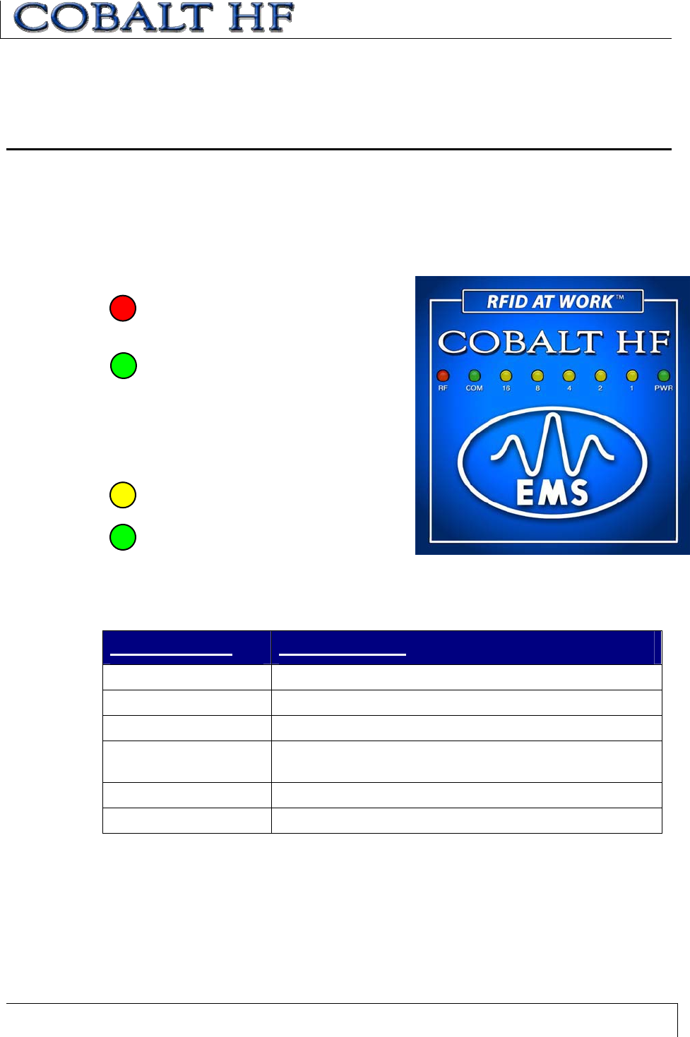
4.1 LED DESCRIPTIONS
RF LED, color is red. The RF LED will
light when RF power is being
transmitted.
COM LED, color is green. The COM
(communications) LED indicates that
data is being transmitted. Upon receiving
a command, the COM LED will begin flashing
ON and OFF. After the controller completes
the operation and generates a command
response, the COM LED flashing will halt.
NODE ID LEDs (x5), colors are yellow
(see table below).
PWR LED, color is green. The PWR
(power) LED will remain ON while power
is applied to the Cobalt HF Controller.
NODE ID LED INDICATOR DEFINITIONS
NODE ID LED DESCRIPTION
Node ID 1 RS232 enabled
Node ID 2 RS422 enabled
Node ID 4 USB enabled
Node ID 8 Default IP Address enabled:
196.169.253.110 (-IND model only)
Node ID 16 Custom IP Address enabled (-IND model only)
All 5 Node ID LEDs LEDs Display Node ID in binary format (-485 model only)
Table 4-1: Node ID LED Indicator Definitions

CHAPTER 4: LED STATUS
COBALT HF RFID CONTROLLERS OPERATOR’S MANUAL
P/N: 17-1320 REV 01 (03-06) PAGE 50 OF 116
4.2 ERROR CONDITIONS
When an error occurs, the red RF LED and one or more yellow LEDs will flash in unison.
The yellow LEDs represent the error code in binary notation. These LEDs will continue to
flash the error code until a valid command is received by the controller. If an
unrecoverable error occurs, the LEDs will continuously flash the error code until the
Cobalt Controller has been reset.
See Chapter 8 for a list of error codes and their descriptions.