BancTech orporated 53223-RTM RFID System User Manual 11 06 21 700
BancTech, Incorporated RFID System 11 06 21 700
Contents
- 1. users manual
- 2. attachement page to users manual
users manual

1
HF Reader System Series 6000
S6350 Multi-Protocol Reader Modules: RI-STU-TRDC-01 & 02
Reference Guide
11-06-21-700 September 2001
A TEXAS INSTRUMENTS TECHNOLOGY

September 2001 S6350 Reader Reference Guide
2
Second Edition - September 2001
This is the second edition of this manual. It describes the S6350 Reader (formerly
published as the Series 5000 RI-STU-TRDC-00 Reader Reference Guide).
It contains a description of the following reader modules:
Reader Module with Right-Angle Connector RI-STU-TRDC-01
Reader Module with Straight Connector RI-STU-TRDC-02
Texas Instruments (TI) reserves the right to make changes to its products or services or
to discontinue any product or service at any time without notice. TI provides customer
assistance in various technical areas, but does not have full access to data concerning
the use and applications of customer’s products
Therefore, TI assumes no liability and is not responsible for customer applications or
product or software design or performance relating to systems or applications
incorporating TI products. In addition, TI assumes no liability and is not responsible for
infringement of patents and/or any other intellectual or industrial property rights of third
parties, which may result from assistance provided by TI.
TI products are not designed, intended, authorized or warranted to be suitable for life
support applications or any other life critical applications which could involve potential
risk of death, personal injury or severe property or environmental damage.
The RFID Systems logo, TIRIS logo, the words RFID Systems, TIRIS and Tag-it are
trademarks or registered trademarks of Texas Instruments Incorporated (TI).
Copyright © 2001 Texas Instruments Incorporated (TI).
This document may be downloaded onto a computer, stored and duplicated as
necessary to support the use of the related TI products. Any other type of duplication,
circulation or storage on data carriers in any manner not authorized by TI represents a
violation of the applicable copyright laws and shall be prosecuted.
3
Read This First
About This Manual
This reference guide for the S6350 High-frequency (13.56Mhz) Reader is designed for use by TI
customers who are engineers experienced with RFID Systems and Radio Frequency
Identification Devices (RFID).
Device Name Firmware
Version Hardware Configuration
RI-STU-TRDC-01 1.4 (ISO 15693-3) Right-Angle Connector
RI-STU-TRDC-02 1.4 (ISO 15693-3) Straight Connector
Regulatory, safety and warranty notices that must be followed are provided in Chapter 4.
Conventions
The following pictograms and designations are used in the operating instructions:
WARNING:
A WARNING IS USED WHERE CARE MUST BE
TAKEN, OR A CERTAIN PROCEDURE MUST BE
FOLLOWED, IN ORDER TO PREVENT INJURY OR
HARM TO YOUR HEALTH.
CAUTION:
This indicates information on conditions, which must be
met, or a procedure, which must be followed, which if not
needed could cause permanent damage to the system.
Note:
Indicates conditions, which must be met, or procedures which must
be followed, to ensure proper functioning.
Information:
Indicates conditions or procedures that should be followed to ensure
proper functioning of the system.
Preface

September 2001 S6350 Reader Reference Guide
4
If You Need Assistance
Application Centers are located in Europe, North and South America, the Far East and
Australia to provide direct engineering support.
For more information, please contact your nearest TI-RFID Systems Sales and
Application Center. The contact addresses can be found on our home page:
http://www.ti-rfid.com.
Numerical Representations
Unless otherwise noted, numbers are represented as decimal.
Hexadecimal numbers are represented with the suffix hex, e.g. A5F1hex
Binary numbers are represented with the suffix 2, e.g. 10112
Byte representations: the least significant bit (lsb) is bit 0 and the most significant bit
(msb) is bit 7.

September 2001 S6350 Reader Reference Guide
5
Document Overview
Chapter 1: Introduction......................................................................................................6
1.1 Description..................................................................................................7
1.1.1 Programming Interface...........................................................................7
1.2 Summary of Chapters and Appendixes .........................................................7
Chapter 2: Harware Description.........................................................................................8
2.1 General Specification...................................................................................9
2.1.1 Functional Requirements........................................................................9
2.1.2 Power Supply........................................................................................9
2.1.3 Output Power........................................................................................9
2.1.4 Required Antenna Parameters..............................................................10
2.1.5 Input / output pins (CN1 pins 3 and 4)...................................................10
2.1.6 Baseband receiver...............................................................................11
2.1.7 Connector Details................................................................................11
2.1.8 16-pin Header Connector CN1..............................................................11
2.1.9 RI-STU-TRDC-01 (CN1) Pin Assignments.............................................12
2.1.10 RI-STU-TRDC-02 (CN1) Pin Assignments............................................13
2.2 Mechanical Specifications ..........................................................................14
2.2.1 RI-STU-TRDC-01 with 16-pin Right-Angle Connector.............................14
2.2.2 RI-STU-TRDC-02 with 16-pin Straight Header Connector.......................15
Chapter 3: Reader Protocol.............................................................................................16
3.1 Serial Protocol Definition............................................................................17
3.1.1 Request Packet Format (Host to Reader)..............................................17
3.1.2 Response Packet Format (Reader to Host)............................................18
3.1.3 Command Flags Request.....................................................................18
3.1.4 Command Flags Response..................................................................19
3.1.5 BCC....................................................................................................19
3.1.6 Example Request Packet .....................................................................19
3.2 Command Definitions.................................................................................20
3.2.1 Tag-it™ HF Command Definitions.........................................................20
3.2.2 Miscellaneous Commands....................................................................23
3.2.3 ISO/IEC FCD 15693 Part 3 Transmission Protocol.................................26
3.2.3.1 ISO/IEC 15693-3 Command Codes....................................................26
3.2.3.2 Request/Response Packet Format for ISO/IEC 15693-3......................26
3.2.3.3 Mandatory Commands ......................................................................30
3.2.3.4 Optional Commands..........................................................................32
Chapter 4: Regulatory and Warranty Notices..................................................................42
4.1 FCC Conformity.........................................................................................43
4.2 ETSI Conformity........................................................................................43
4.3 CE Conformity...........................................................................................43
4.4 Warranty and Liability ................................................................................43
Appendix B: Downloading Data to FLASH Memory .........................................................44
Appendix B: Error Codes.................................................................................................45

September 2001 S6350 Reader Reference Guide
6
Introduction
Topic Page
1.1 Description..................................................................................................7
1.1.1 Programming Interface...........................................................................7
1.2 Summary of Chapters and Appendixes .........................................................7
Chapter 1
September 2001 S6350 Reader Reference Guide
7
1.1 Description
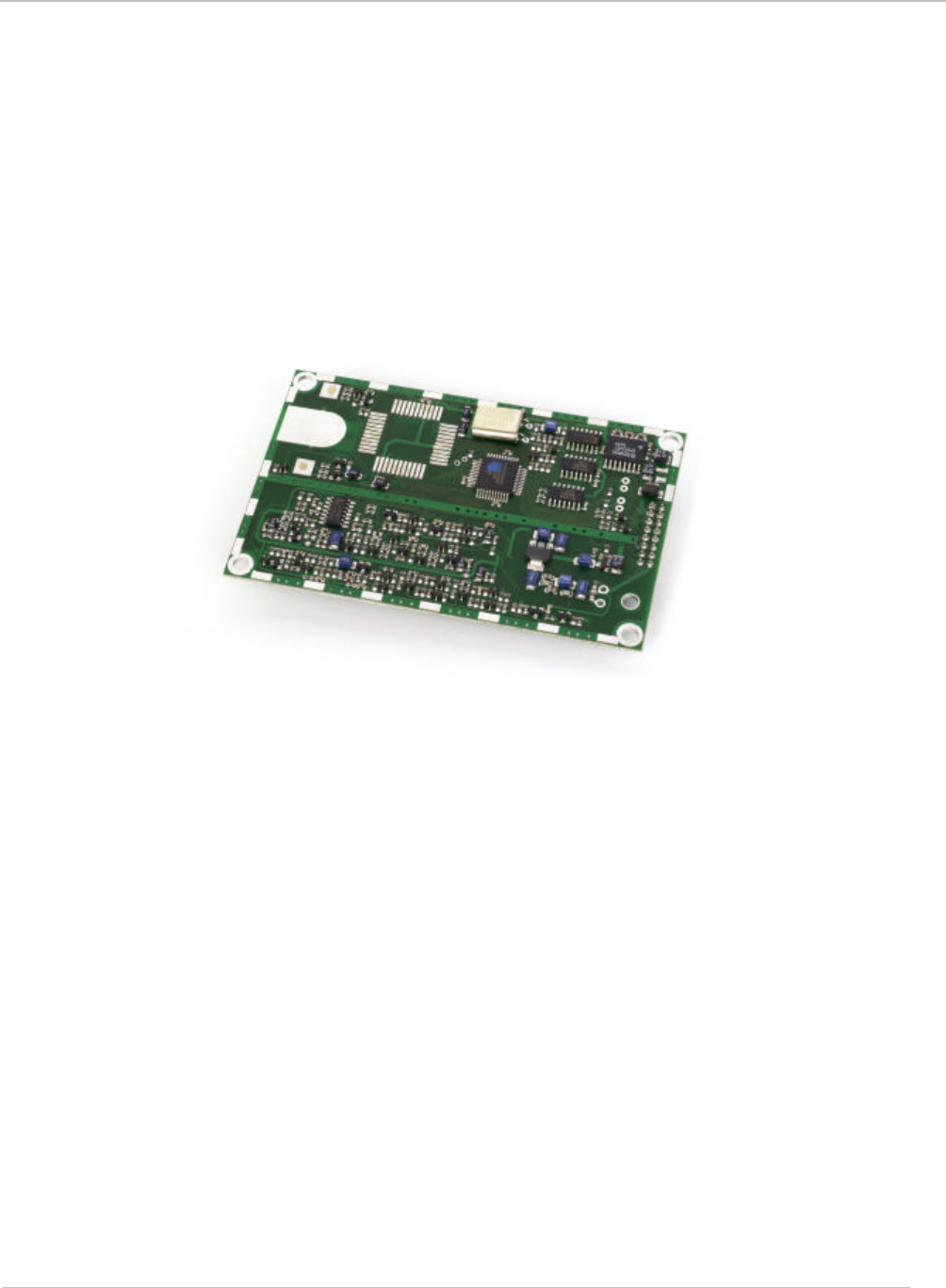
This document describes the features and operational characteristics of the RI-STU-TRDC-01 & -02
S6350 High Frequency Multi-Protocol Readers. The RI-STU-TRDC-02 reader is shown in Figure 1.
The S6350 Reader operates at a frequency of 13.56MHz and is compatible with both standard and
ISO/IEC 15693 Tag-it inlays and tags. This reference guide provides the details that are necessary to
properly interface and use the reader as a part of an integrated system.
In compliance with the ISO/IEC 15693 standard, a global open standard for optimal use under
different regulatory and noise environments around the world, the S6350 Reader allows for the
interoperability of inlays and tags from multiple manufacturers.
Figure 1: S6350 High Frequency Reader
1.1.1 Programming Interface
The S6350 Reader is designed to operate as a part of a host-based reader system, which essentially
relegates the reader to be a slave to the host. Host-to-Tag-it reader serial communications are
accomplished within data packets whereby communications from the host to the reader are known as
requests, and replies from the reader to the host are known as responses. This communication
occurs at RS-232 levels using 57,000 baud, 8 data bits, 1 start bit, 1 stop bit and no parity. By
definition, the host is always the primary station and initiates all communication sequences. These
sequences consist of request/response pairs where the host waits for a response prior to continuing.
1.2 Summary of Chapters and Appendixes
Chapter 1: Introduction
Chapter 2: Hardware Description
Chapter 3: Reader Protocol
Chapter 4: Regulatory & Warranty Notices
Appendix A: Downloading Data
Appendix B: Error Codes

8
Hardware Description
Topic Page
2.1 General Specification...................................................................................9
2.1.1 Functional Requirements........................................................................9
2.1.2 Power Supply........................................................................................9
2.1.3 Output Power........................................................................................9
2.1.4 Required Antenna Parameters..............................................................10
2.1.5 Input / output pins (CN1 pins 3 and 4)...................................................10
2.1.6 Baseband receiver...............................................................................11
2.1.7 Connector Details................................................................................11
2.1.8 16-pin Header Connector CN1..............................................................11
2.1.9 RI-STU-TRDC-01 (CN1) Pin Assignments.............................................12
2.1.10 RI-STU-TRDC-02 (CN1) Pin Assignments............................................13
2.2 Mechanical Specifications ..........................................................................14
2.2.1 RI-STU-TRDC-01 with 16-pin Right-Angle Connector.............................14
2.2.2 RI-STU-TRDC-02 with 16-pin Straight Header Connector.......................15
Chapter 2
September 2001 S6350 Reader Reference Guide
9
2.1 General Specification
This chapter describes the electrical and mechanical specifications of the S6350 RI-STU-TRDC-02
reader. Operating at a frequency of 13.56 MHz, this low profile, low power device is designed to be
easily integrated into many systems as an embedded device. All reader I/O is accomplished through
the use of a 16-pin header connector (labeled as CN1), to include all communication, which is
asynchronous RS232 as controlled by a host system.
2.1.1 Functional Requirements
The following parameters define the functional requirements and operational environment of the
S6350 reader.
Parameter Specifications
Operating temperature -20oC to +70o C
Storage temperature
(500 hours) -40oC to +85oC
Thermal shock -40oC to +85oC, using MIL-STD-810E, Method 503.3,
for 100 cycles duration, 30 minutes per temperature.
Mechanical shock 5 Gs at 10 ms, half sinusoidal waves, 6 axes (MIL STD-
801E, Method 516.3)
Vibration 15 Hz to 500 Hz, 1 g peak, 30 minutes sweep,
logarithmic (MIL-STD-810E, Method 514.4)
Humidity 500 hours at 80% humidity, non-condensing at 70oC
Operating frequencies 13.56 MHz up-link and down-link
Transponder types 13.56 MHz TI Tag-it™ tag (Standard & ISO tag)
Standard compliance FCC Part 15, Subpart C, “Intentional Radiator”
2.1.2 Power Supply
Input Voltage 5 ± .5 VDC
Average quiescent current 90mA
Average current during read 200mA (for TAG-IT tags)
(Dependent on read rate)
Maximum current during read 250mA
2.1.3 Output Power
Output Power 120mW into 50 Ohms (Typical)
CAUTION:
The S 6350 reader is an intentional radiator, and when
integrated, the integrator is subject to meeting FCC Part
15, Subpart C, and similar tenets under European
Standard EN 300330.
September 2001 S6350 Reader Reference Guide
10
2.1.4 Required Antenna Parameters
Impedance 50Ω ± 5Ω at 13.56 MHz
Loaded Q 10 < Q < 30
Note:
As no standard antenna is provided by Texas Instruments for the
S6350 reader, the noted required antenna parameters must be
closely followed by the integrator for the reader to operate properly.
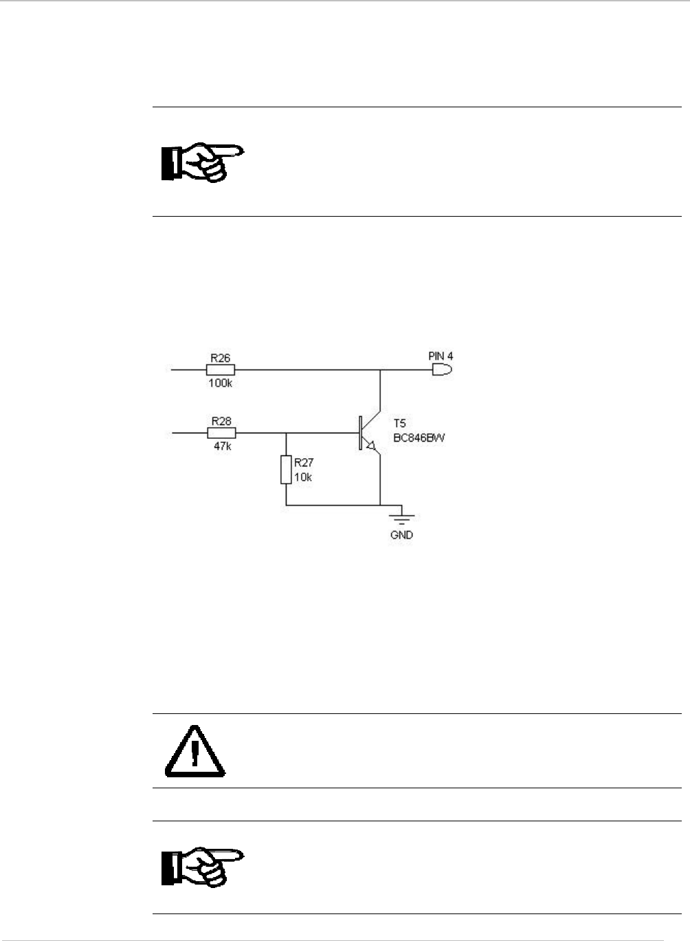
2.1.5 Input / output pins (CN1 pins 3 and 4)
Pins 3 and 4 on CN1 may be configured by software commands to read a logic level input or to
switch an external load to ground (no pull-up is provided).
Figure 2: Example Circuit Diagram of an IO pin
When used as a switch to ground the following ratings should not be exceeded:
Maximum voltage 20V
Maximum current 50mA
CAUTION:
Exceeding this Voltage and Current limit could cause
permanent damage to the reader.
Note:
That if an output has been set by a software command the state will
always read back as a logic 0.
September 2001 S6350 Reader Reference Guide
11
2.1.6 Baseband receiver
Minimum data pulse width 5uS
Maximum data pulse width 500uS
Typical settling time 50uS from the first transition
Note:
The receiver extracts the mean level of the incoming data stream as
a reference. This takes approximately 50uS; therefore the data
output of the receiver is not valid until after this time.
2.1.7 Connector Details
All reader input and output is provided through a 16-pin header connector that is mounted on the
backside of the reader for the RI-STU-TRDC-02 and on the component side for the RI-STU-
TRDC-01. The details and orientation of each connector pin are provided in the following tables.
2.1.8 16-pin Header Connector CN1
Pin Function
1 0 Volts
2+5 Volts
3Open collector output / data input 2
4Open collector output / data input 1
5RS232 TxD (output from reader)
6RS232 RxD (input to reader)
7No connection (antenna guard)
8Antenna screen
9Antenna signal
10 No connection (antenna guard)
11 RS232 ground
12 No connection (reserved for future expansion)
13 No connection (reserved for future expansion)
14 No connection (reserved for future expansion)
15 No connection (reserved for future expansion)
16 No connection (reserved for future expansion)
CAUTION:
Only pins 8 and 9 of connector CN1 should be used for
the antenna connection.
September 2001 S6350 Reader Reference Guide
12
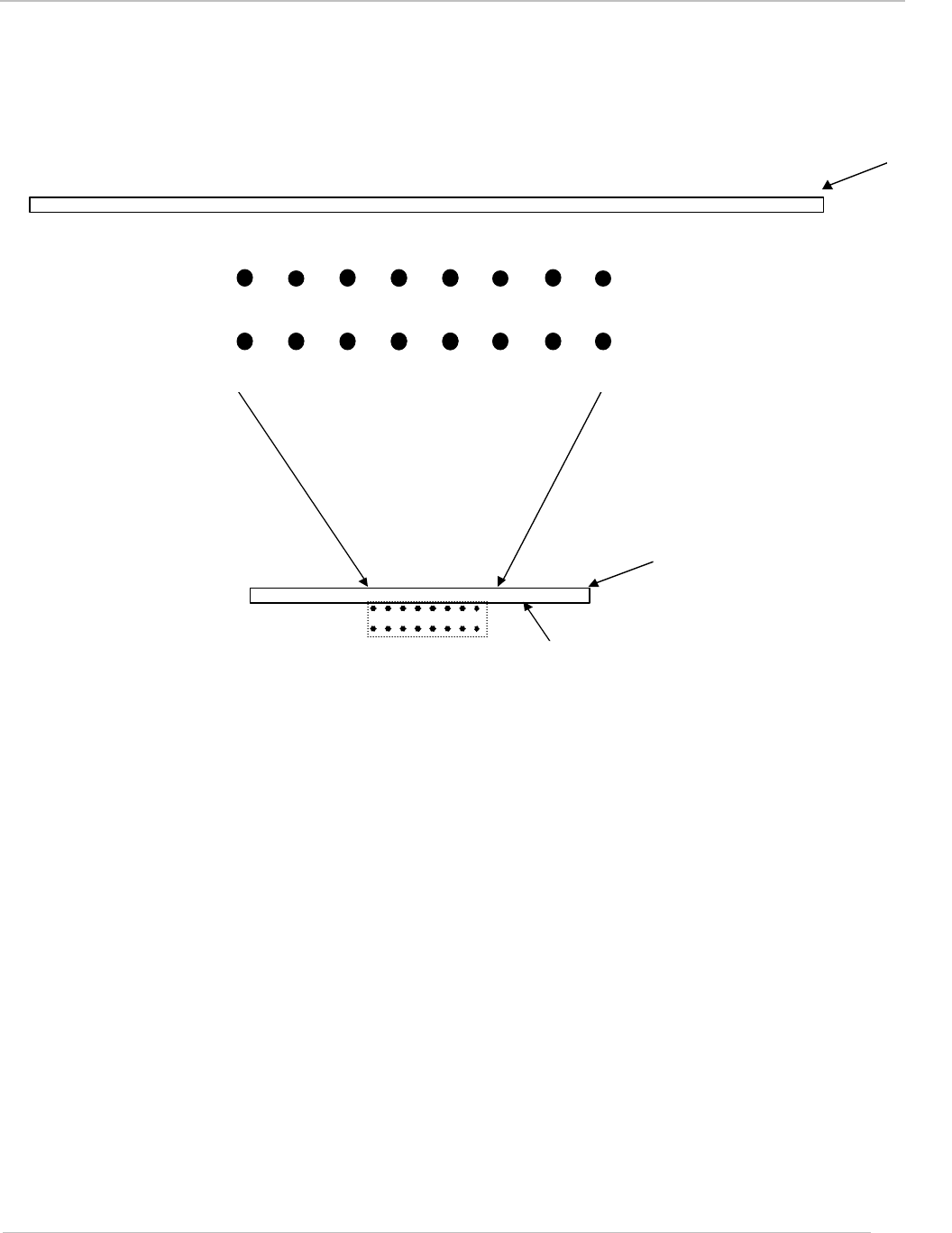
2.1.9 RI-STU-TRDC-01 (CN1) Pin Assignments
1234567 8
16 15 14 13 12 11 10 9
Figure 3: 16-pin Right-Angle Header
Connector (CN1)
1Component Side
PCB
PCB
September 2001 S6350 Reader Reference Guide
13
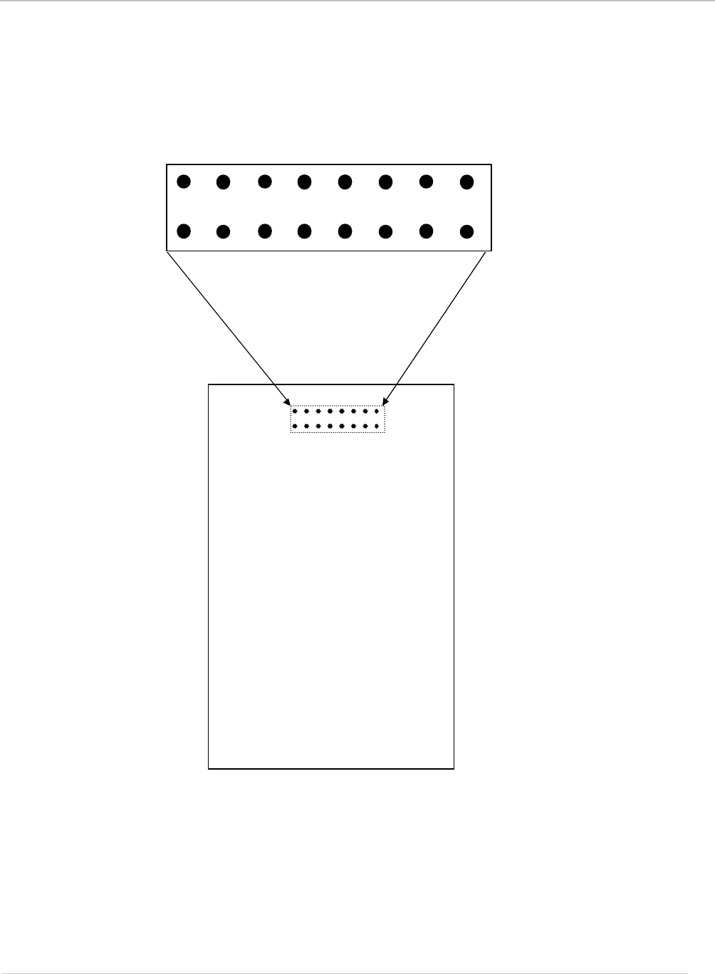
2.1.10 RI-STU-TRDC-02 (CN1) Pin Assignments
`
1234567 8
16 15 14 13 12 11 10 9
Figure 4: 16-pin Header Connector
(CN1) viewed from component side.
COMPONENT SIDE
1
September 2001 S6350 Reader Reference Guide
14
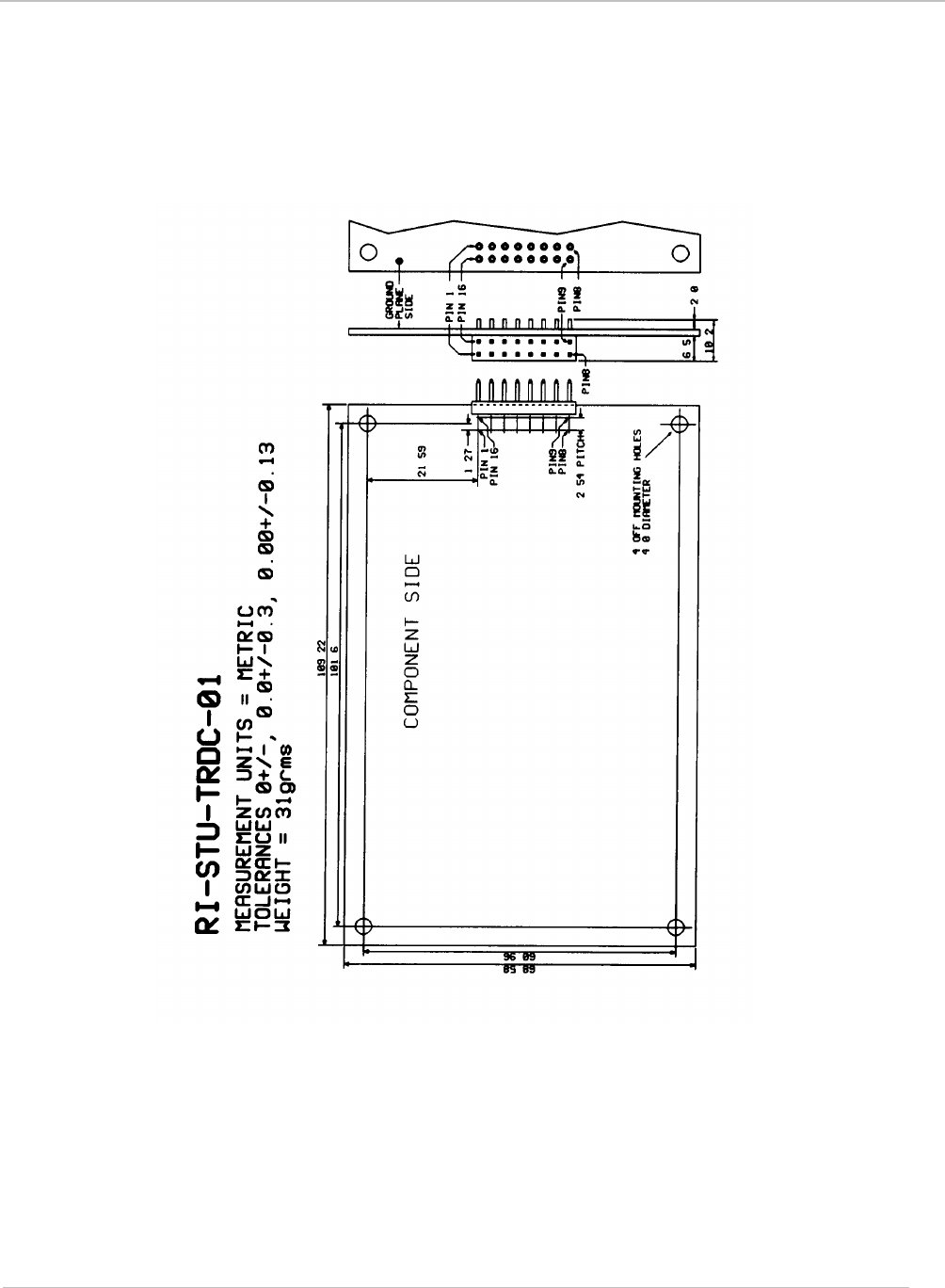
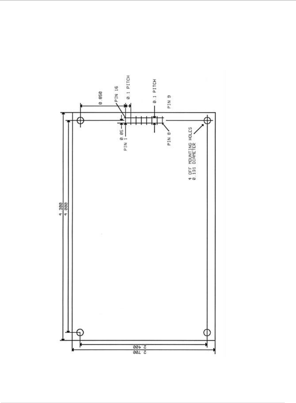
2.2 Mechanical Specifications
2.2.1 RI-STU-TRDC-01 with 16-pin Right-Angle Connector
Figure 5: Note: All dimensions are in metric
September 2001 S6350 Reader Reference Guide
15
2.2.2 RI-STU-TRDC-02 with 16-pin Straight Header Connector
Figure 6: Note: All dimensions are in inches
COMPONENT SIDE

16
Reader Protocol
Topic Page
3.1 Serial Protocol Definition............................................................................17
3.1.1 Request Packet Format (Host to Reader)..............................................17
3.1.2 Response Packet Format (Reader to Host)............................................18
3.1.3 Command Flags Request.....................................................................18
3.1.4 Command Flags Response..................................................................19
3.1.5 BCC....................................................................................................19
3.1.6 Example Request Packet .....................................................................19
3.2 Command Definitions.................................................................................20
3.2.1 Tag-it™ HF Command Definitions.........................................................20
3.2.2 Miscellaneous Commands....................................................................23
3.2.3 ISO/IEC FCD 15693 Part 3 Transmission Protocol.................................26
3.2.3.1 ISO/IEC 15693-3 Command Codes....................................................26
3.2.3.2 Request/Response Packet Format for ISO/IEC 15693-3......................26
3.2.3.3 Mandatory Commands ......................................................................30
3.2.3.4 Optional Commands..........................................................................32
Chapter 3

September 2001 S6350 Reader Reference Guide
17
3.1 Serial Protocol Definition
The S6350 reader accepts and sends data at RS232 levels, 57600 baud, 8 data bits, 1 start bit,
1 stop bit and no parity. The data packet from the host to the reader is known as the request
and the reply from the reader to the host as the response. The host is always the primary station
and initiates all communication sequences. These consist of request/response pairs where the
host waits for a response before continuing. The S6350 reader does not use the node address.
3.1.1 Request Packet Format (Host to Reader)
Field Name SOF
Field Size 1 byte
Field Value 01hex
Purpose Start of Frame
Field Name Length
Field Size 2 byte LSB first
Field Value Packet dependent
Purpose Describes the length of the whole packet including SOF
Field Name Node Address
Field Size 2 byte LSB first
Field Value 0000hex
Purpose Must be 0000hex for upward compatibility
Field Name Command flags
Field Size 1 byte
Field Value Varies by command
Purpose Specifies the action to be taken by the reader
Field Name Command
Field Size 1 byte
Field Value Varies by command
Purpose Specifies the action to be taken by the reader
Field Name Data
Field Size 0 to xx bytes
Field Value Command dependent
Purpose Contains the parameters and data for the command
Field Name BCC
Field Size 2 bytes
Field Value 16 bit LRC of the preceding packet including the SOF
Purpose Allows the reader to validate the correct reception of the request
packet

September 2001 S6350 Reader Reference Guide
18
3.1.2 Response Packet Format (Reader to Host)
Field Name SOF
Field Size 1 byte
Field Value 01hex
Purpose Start of Frame
Field Name Length
Field Size 2 byte LSB first
Field Value Packet dependent
Purpose Describes the length of the whole packet including SOF
Field Name Node Address
Field Size 2 byte LSB first
Field Value 0000hex
Purpose always 0000hex
Field Name Command flags
Field Size 1 byte
Field Value Varies by command
Purpose Specifies the action just taken by the reader
Field Name Command
Field Size 1 byte
Field Value Varies by command
Purpose Specifies the action just taken by the reader
Field Name Data
Field Size 0 to 23 bytes
Field Value Command dependent
Purpose Contains the parameters and data for the command just processed
Field Name BCC
Field Size 2 bytes
Field Value 16 bit LRC of the preceding packet including the SOF
Purpose Allows the host to validate the correct reception of the response
packet
3.1.3 Command Flags Request
The command flags in the request packet control the actions of the reader. The meanings of the
bits are defined below.
Bits 0-3 Reserved for future use and should be set to ‘0’ for upward
compatibility.
Bit 4 Is the address flag and if set, the command is only performed on
transponders whose address matches the data section of the packet.
Bits 5-7 Reserved for future use and should be set to ‘0’ for upward
compatibility.

September 2001 S6350 Reader Reference Guide
19
3.1.4 Command Flags Response
The command flags in the response packet report the actions of the reader. The meanings of
the bits are defined below.
Bits 0-3 Reserved for future use.
Bit 4 Error flag. If this flag is set the command was unsuccessful and the
data section of the response packet contains the error code. (See
section Appendix B for a list of error codes.)
Bits 5-7 Reserved for future use.
3.1.5 BCC
A Block Check Character (BCC) is used for error detection and is attached to the end of the
packet. The 16 bit BCC is calculated on all the bytes of the packet including the SOF. The BCC
consists of two parts: the LSbyte is a Longitudinal Redundancy Check (LRC) and the MSbyte is
the ones compliment of the LRC. The LRC is calculated by performing a cumulative Exclusive-
OR operation on all the bytes of the packet.
3.1.6 Example Request Packet
01 hex SOF
0A hex LSbyte of length
00 hex MSbyte of length
00 hex LSbyte of node address
00 hex MSbyte of node address
00 hex Command flags (Not addressed)
02 hex Command (Tag-itTM Read block)
01 hex Data (Block number 1)
08 hex LSbyte of Checksum
F7 hex MSbyte of Checksum

September 2001 S6350 Reader Reference Guide
20
3.2 Command Definitions
3.2.1 Tag-it™ HF Command Definitions
Command Function (Tag-it HF) Command Code
Read Single Non-addressed & Addressed Block 02hex
Write Single Non-addressed & Addressed Block 03hex
Lock Single Non-addressed & Addressed Block 04hex
Read Transponder Details 05hex
Special Read Block Command 0Fhex
Read Block Command (02hex)
Reads a single block of data from a Tag-itTM transponder. If the address flag is set, the
address forms the first part of the data section (LSbyte first), followed by a single byte
containing the block number to be read. If the address flag is clear the data section
only contains the block number.
Example
Read block 3 of a Tag-itTM transponder whose address is 0134A4D5hex
Request packet
01 0E 00 00 00 10 02 D5 A4 34 01 03 5A A5hex
The response packet is similar to the request packet, with the data section containing
the data received from the transponder (LSbyte first) followed by a single byte
indicating the lock status and then another single byte containing the block address.
The two LSB’s of the lock status byte reflect the two lock bits in the transponder.
Example
Response packet
01 0F 00 00 00 00 02 33 22 11 00 00 03 0F F0 hex
00112233hex read from unlocked block 3 of a Tag-itTM transponder.
Write Block Command (03hex)
Writes a single block of data to a Tag-itTM transponder. If the address flag is set, the
address forms the first part of the data section, followed by a single byte containing the
block number to be written. The data to be written follows the block number. If the
address flag is clear the data section only contains the block byte and the data to be
written.
Example
Write Block 4 of a Tag-itTM transponder whose address is 000134A4hex with data
01234567hex
Request packet
01 12 00 00 00 10 03 A4 34 01 00 04 67 45 23 01 95 6Ahex
The response packet is similar to the request packet; with the data section containing
00hex for a successful write operation.

September 2001 S6350 Reader Reference Guide
21
Example
Response packet
01 0A 00 00 00 00 03 00 08 F7hex
Successful write.
Lock Block Command (04hex)
Locks a single block of data in a Tag-itTM transponder. If the address flag is set, the
address forms the first part of the data section, followed by a single byte containing the
number of the block to lock.
Example
Lock Block 4 of a Tag-itTM transponder whose address is 000134A4hex
Request packet
01 0E 00 00 00 10 04 A4 34 01 00 04 8E 71hex
The response packet is similar to the request packet, with the data section containing
00hex for a successful lock operation.
Example
Response packet
01 0A 00 00 00 00 04 00 0F F0hex
Successful lock.
Read Transponder Details Command (05hex)
Reads the details of a Tag-itTM transponder. If the address flag is set, the address
forms the data section.
Example
Read the details of a Tag-itTM transponder non-address
Request packet
01 09 00 00 00 00 05 0D F2hex
The response packet is similar to the request packet, with the data section containing
the transponder address (4 bytes), manufacturers code (1 byte), transponder version
number (2 bytes), the number of blocks (1 byte) and the number of bytes per block
(1byte).
Example
Response packet
01 12 00 00 00 00 05 A4 34 01 00 01 05 00 08 04 8F 70hex
Transponder ID 000134A4hex
Manufacturers Number 01hex
Version Number 0005hex
Number of blocks 08hex
Number of bytes per block 04hex
Special Read Block Command (0Fhex)
Reads blocks of data from a Tag-itTM transponder. The address flag should not be
used. The data section contains a single byte detailing the blocks to be read. Each bit
of this byte represents a block of data (bit 0 = block 0 etc) if a bit is set then that block
is read. If the data byte is zero then only the SID is returned. The SID is always
retrieved first and then used to read the selected blocks in addressed mode.

September 2001 S6350 Reader Reference Guide
22
Example
Read blocks 0, 3 & 4 of a Tag-itTM transponder (data byte = 00011001bin = 19hex)
Request packet
01 0A 00 00 00 00 0F 19 1D E2hex
The data section of the response packet contains:
The SID address (LSbyte first),
Block 0 data (if selected) followed by a single byte indicating the lock status and then
another single byte containing the block address,
Block 1 data (if selected) followed by a single byte indicating the lock status and then
another single byte containing the block address,
Block 7 data (if selected) followed by a single byte indicating the lock status and then
another single byte containing the block address,
(The two LSB’s of the lock status bytes reflect the blocks two lock bits in the
transponder.)
Example
Response packet
01 1F 00 00 00 00 0F 23 4F 10 00 EF CD AB 89 00 00 33 22 11 00 00 03
67 45 23 01 00 04 6A 95 hex
00104F23hex SID
89ABCDEFhex read from unlocked block 0 of a Tag-itTM transponder.
00112233hex read from unlocked block 3 of a Tag-itTM transponder.
01234567hex read from unlocked block 4 of a Tag-itTM transponder.

September 2001 S6350 Reader Reference Guide
23
3.2.2 Miscellaneous Commands
Command Function Command Code
Initiate FLASH Loader Command D0hex
Send Data to FLASH Command D8hex
Reader Version Command F0hex
Read Inputs Command F1hex
Write Reader Outputs Command F2hex
RF Carrier on/off Command F4hex
Initiate FLASH Loader Command (D0 hex)
This command is used to initialize and transfer control to the FLASH loader software.
Example
Request packet
01 09 00 00 00 00 D0 D8 27hex
The response packet is similar to the request packet with the data section containing
‘00’ if successful.
Example
Response packet
01 0A 00 00 00 00 D0 00 DB 24hex
FLASH loader initialised and control transferred.
Send Data to FLASH Command (D8hex)
This command is used to load data into the FLASH memory.
Example
Request packet
01 8D 00 00 00 00 D8 <132 bytes of data> <2 byte checksum> hex
The Data section must always contain 132 bytes
The response packet data section contains ‘00’ if successful.
Example
Response packet
01 0A 00 00 00 00 D8 00 D3 2Chex
The section of FLASH memory was programmed correctly.
Reader Version Command (F0hex)
Requests the version number of the reader. The flags are ignored for this command.
Example
Get the version number of the reader.
Request packet
01 09 00 00 00 00 F0 F8 07hex
The response packet is similar to the request packet with the data section containing
the 2 byte version number LSB first followed by a single byte representing the reader
type.

September 2001 S6350 Reader Reference Guide
24
Reader Type
Example
Response packet
01 0C 00 00 00 00 F0 40 01 07 BB 44hex
The version number is 1.4
The reader type response can be defined as follows:
Type 07 = Indicates that the reader has been successfully loaded with the noted
application firmware version number (in this example, version 1.4).
Type 00 = Indicates that the reader has not been loaded with application firmware, but
does have the boot-loader firmware in place with which to download the appropriate
application firmware. (Please refer to Appendix A: Downloading Data to FLASH
Memory)
Reader inputs Command (F1hex)
Reads the state of the reader inputs. The flags are ignored for this command.
Example
Get the status of the reader inputs.
Request packet
01 09 00 00 00 00 F1 F9 06hex
The response packet is similar to the request packet with the data section containing a
byte representing the state of the inputs. Bit 0 of this byte represents input 1 and bit 1
represents input 2 all other bits are reserved.
Example
Response packet
01 0A 00 00 00 00 F1 01 FB 04hex
Input 1 is at Logic 1
Input 2 is at Logic 0
Write reader outputs Command (F2hex)
Writes the state of the reader outputs. The flags are ignored for this command.
The data section contains 1 byte with bits defined as follows:
Bit 0 1 = Output 1 switched on (output is pulled to ground)
Bit 1 1 = Output 2 switched on (output is pulled to ground)
Bit 2 Reserved
Bit 3 Reserved
Bit 4 1 = Bit 0 enabled (output 1 is controlled)
Bit 5 1 = Bit 1 enabled (output 2 is controlled)
Bit 6 Reserved
Bit 7 Reserved
Example
Switch output 2 on without affecting output 1.
Request packet
01 0A 00 00 00 00 F2 22 DB 24hex

September 2001 S6350 Reader Reference Guide
25
The response packet is similar to the request packet with the data section containing
‘00hex’ for a successful write operation.
Example
Response packet
01 0A 00 00 00 00 F2 00 F9 06hex
Write successful.
RF Carrier on/off Command (F4hex)
Switches the RF carrier on or off. The data section contains one byte FFhex to turn the
carrier on or 00hex to turn the carrier off.
Example
Switch the carrier on.
Request packet
01 0A 00 00 00 00 F4 FF 00 FFhex
The response packet is similar to the request packet with the data section containing
‘00hex’ for a successful operation.
Example
Response packet
01 0A 00 00 00 00 F4 00 FF 00hex
Command successful.
September 2001 S6350 Reader Reference Guide
26
3.2.3 ISO/IEC FCD 15693 Part 3 Transmission Protocol
In addition to supporting the Tag-itTM protocol outlined within the preceding section, the S6350
Mid-Range HF-I Reader complies with the standard RF interface and transmission protocol of
ISO/IEC IS 15693-2 & 3. Please note that each of the ISO protocol command and response
packets outlined within the following sections are contained within the standard reader protocol
as outlined within Section 3.1. It should also be noted that the details of the individual ISO
15693-3 commands are not provided within this document, but are covered within the ISO/IEC
IS 15693-3:2001(E) Anti-Collision and Transmission Protocol document. The ISO 15693-3
commands that are specifically applicable to the S6350 Reader are defined within the following
table.
3.2.3.1 ISO/IEC 15693-3 Command Codes
Command Function Command Code
Inventory (Mandatory Command) 01hex
Stay Quiet (Mandatory Command) 02hex
Read Single Block 20hex
Write Single Block* 21hex
Lock Block* 22hex
Read Multiple Blocks 23hex
Write AFI* 27hex
Lock AFI* 28hex
Write DSFID* 29hex
Lock DSFID* 2Ahex
Get Multiple Block Security Status 2Chex
Note:
* Bit 7 of the ISO 15693 protocol Option_Flag must be set to 1 for
all Write and Lock commands to respond properly.
3.2.3.2 Request/Response Packet Format for ISO/IEC 15693-3
The data packet from the host to the reader is known as the request and the reply from the
reader to the host as the response. The host is always the primary station and initiates all
communication sequences. These consist of request/response pairs where the host waits for a
response before continuing. All ISO/IEC 15693-3 command request packets are contained
within the standard reader command request packet format. In all cases, reader command 60hex
is used to pass through ISO 15693 Part 3 commands to the reader.

September 2001 S6350 Reader Reference Guide
27
The Configuration Byte (ISO Command Data Byte 0)
As detailed in ISO/IEC 15693-2, the Configuration Byte (ISO Command Data Byte 0) is an 8-
bit byte that is used to configure the Data Coding Mode and Modulation Depth of the reader.
Modulation Depth
Bit 4 of the Configuration Byte is used to set Modulation Depth. When set high the
reader is configured for 100% Modulation Depth, when set low the reader will operate
at 10% to 30% (with a 20% nominal setting) Modulation Depth.
Data Coding Mode
Bit 0 of the Configuration Byte is used to set the Data Coding Mode. When set high
the reader is configured for Data Coding Mode 1 / 4; when set low the reader is
configured for Data Coding Mode 1 / 256.
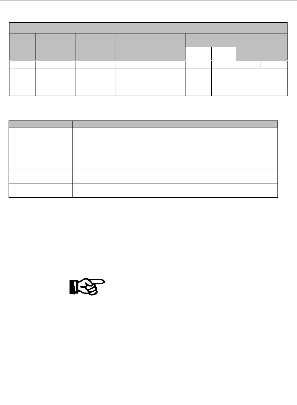
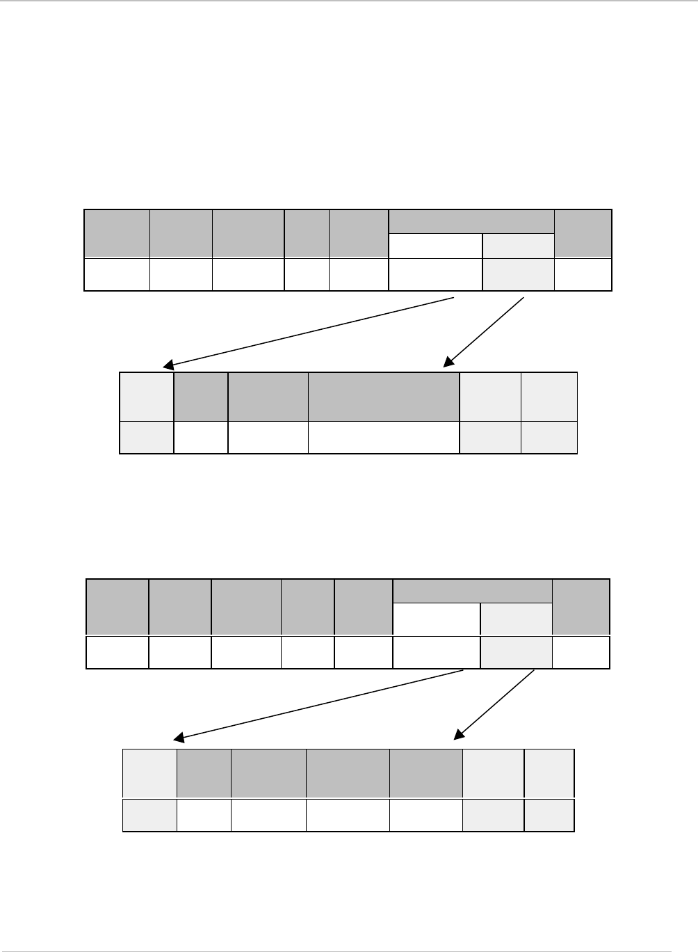
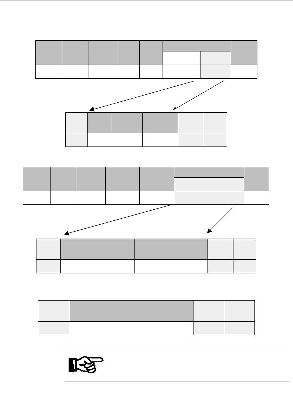
Request Packet Format for ISO/IEC 15693-3
The request packet consists of the header, packet length, node address, command
flags, reader command (60hex), ISO/IEC 15693-3 command/data bytes 0 to some
number “n” (where byte 0 is the configuration byte) and the checksum.
ISO 15693 Command Data Request Structure
The structure of the ISO 15693 Command Data Request is contained within the Data
section of the ISO Command Data, bytes 1 - n. Specific to the S6350 reader, the ISO
15693 SOF, CRC16 and EOF fields must not be included in the message data packet.
Please refer to ISO/IEC 15693-3 for details about the ISO packet format). Specific to
the S6350 reader, the ISO 15693 SOF, CRC16 and EOF fields must not be included.
Note:
The protocol of S 6350 reader does not use the ISO 15693 SOF,
CRC16 and EOF fields within its message packet.
Note:
Please refer to ISO/IEC 15693-3 for details about the ISO message
packet.
September 2001 S6350 Reader Reference Guide
28
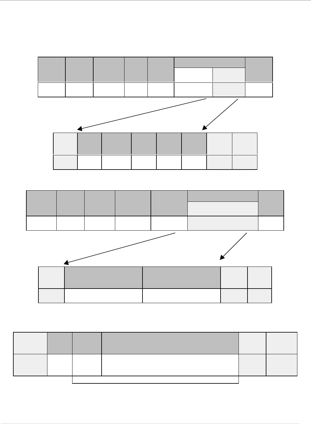
Request Packet Format
Standard reader Request Packet Format (See Section 3.1)
ISO Command
Data
Header Packet
Length Node
Address Command
Flag Command
Config.
Byte Data
Checksum
‘01hex’LSB MSB LSB MSB Flags ‘60hex’XXhex Data Byte 1 Byte 2
Byte 0 bytes
1 - n
1 byte 2 bytes 2 bytes 1 byte 1 byte
1 byte n
bytes
2 bytes
Request Packet Description
Field Length Description
Header 1 byte Defines the start of the packet (01hex).
Packet Length 2 bytes Defines the length of the packet, including checksum.
Node Address 2 bytes Defines the Node address of the reader.
Command Flags 1 byte Defines how a command will be executed.
Command 1 byte Defines the command for the reader to execute (60hex for
ISO 15693-3 commands)
Data 0 - n
bytes Defines the data required by the reader for a command.
Checksum 2 bytes Byte 1 is an XOR checksum of all elements from the
header to the last byte
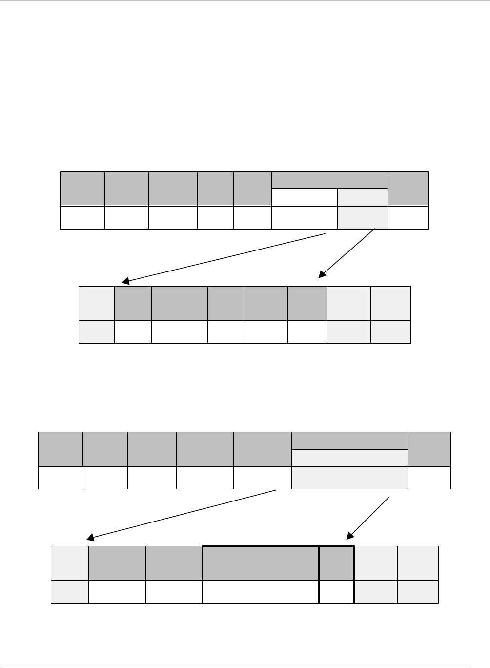
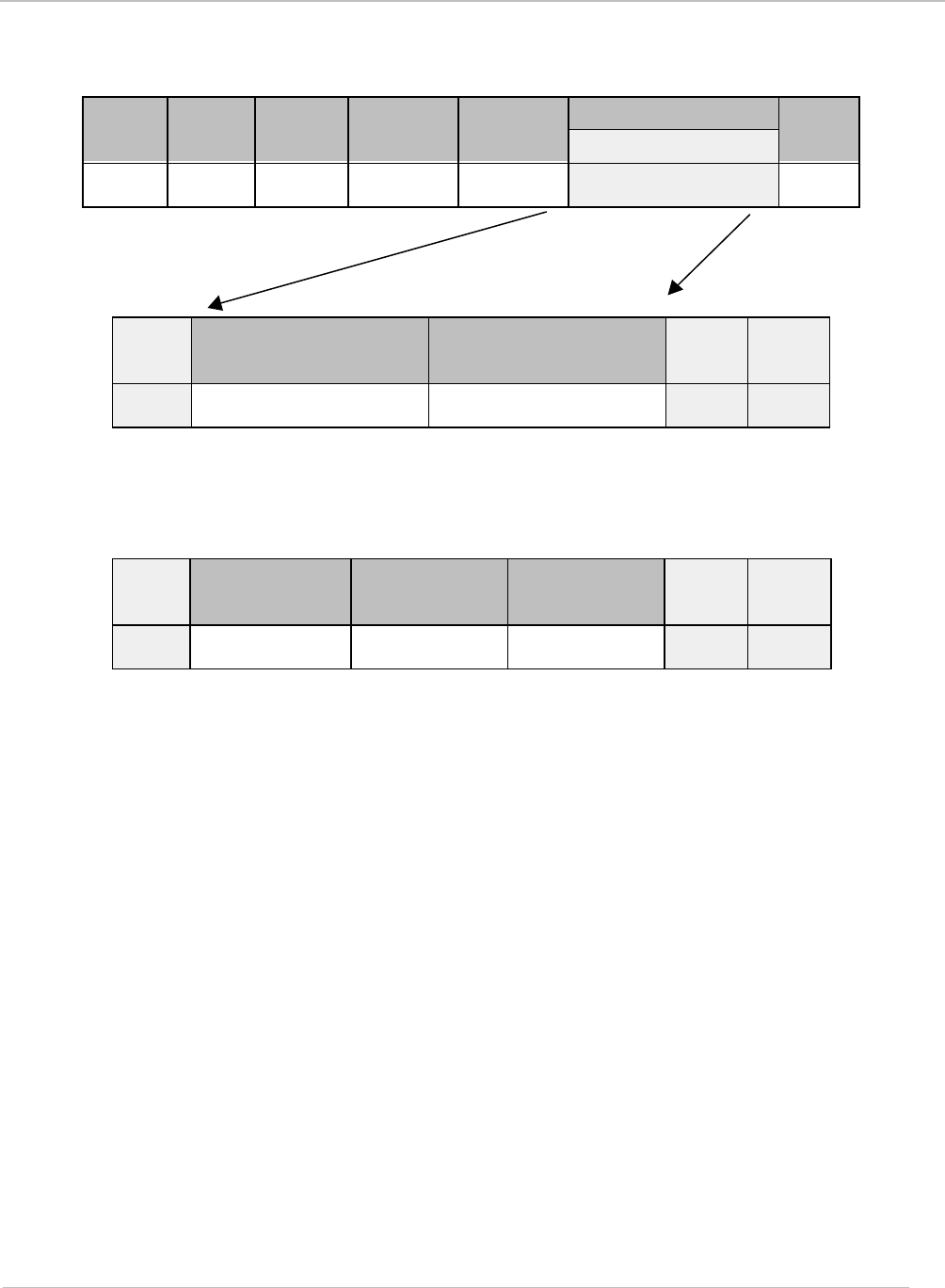
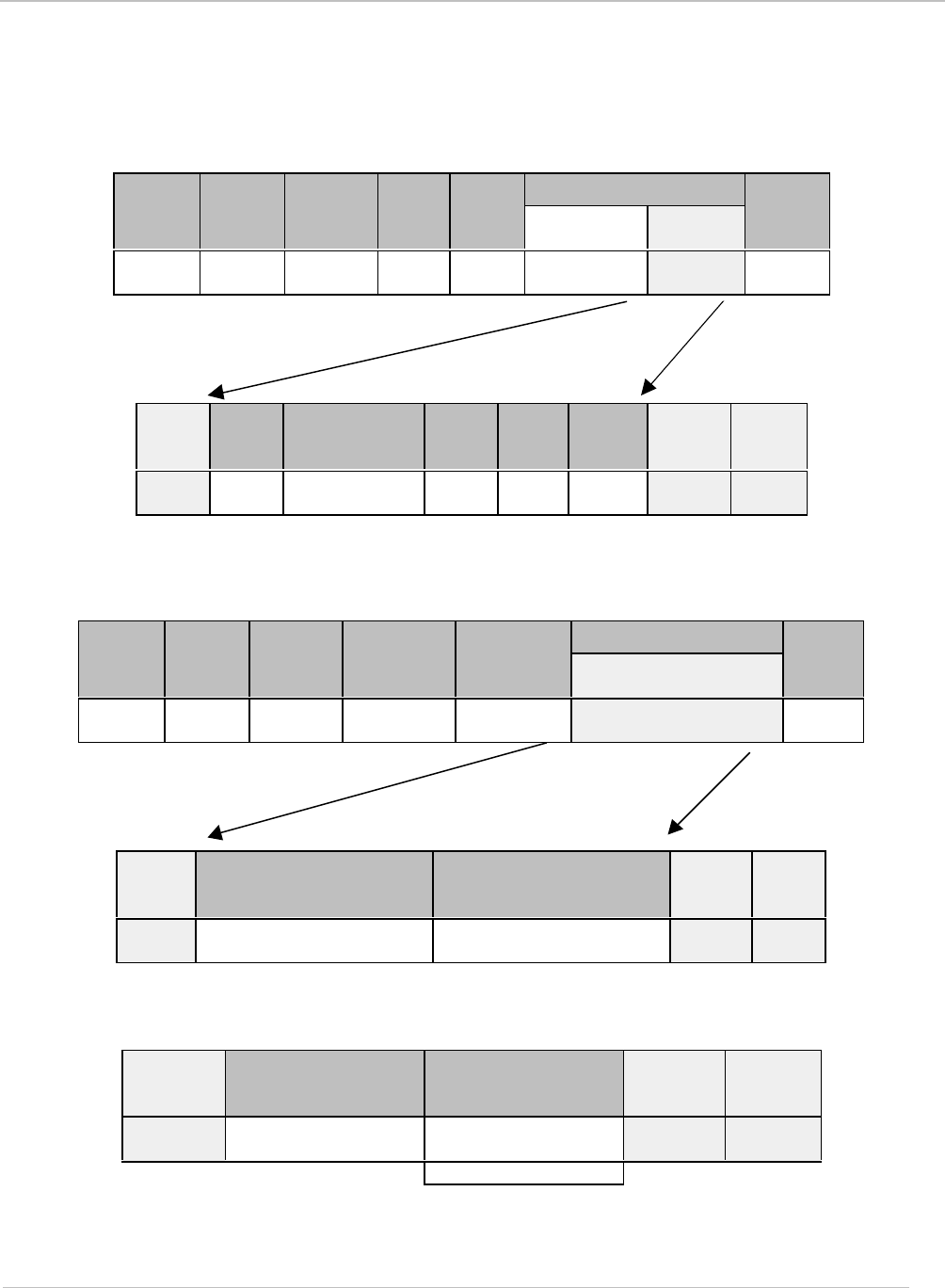
Response Packet Format for ISO/IEC 15693-3
Similar to the request packet, the response packet consists of the header, packet length, node
address, command flags, reader command (60hex), ISO/IEC 15693-3 command/data bytes 0 to
some number “m” and the checksum.
The ISO Response Data packet can come in one of two possible generic formats: (a) One for
the ISO Inventory Response, and (b) all other ISO responses. These will be highlighted in the
following sections.
Note:
With the exception of the ISO Inventory Response packet, the format
for each standard response packet is the same.
The Error Byte (ISO Response Data Byte 0)
There are three possible reader errors that can be generated in response to an ISO 15693
command. This error code will be returned within the Error Byte (Byte 0) of the ISO
Response Data. The error codes are as follows:
01hex Transponder not found
02hex Command not supported
04hex Invalid flags

September 2001 S6350 Reader Reference Guide
29
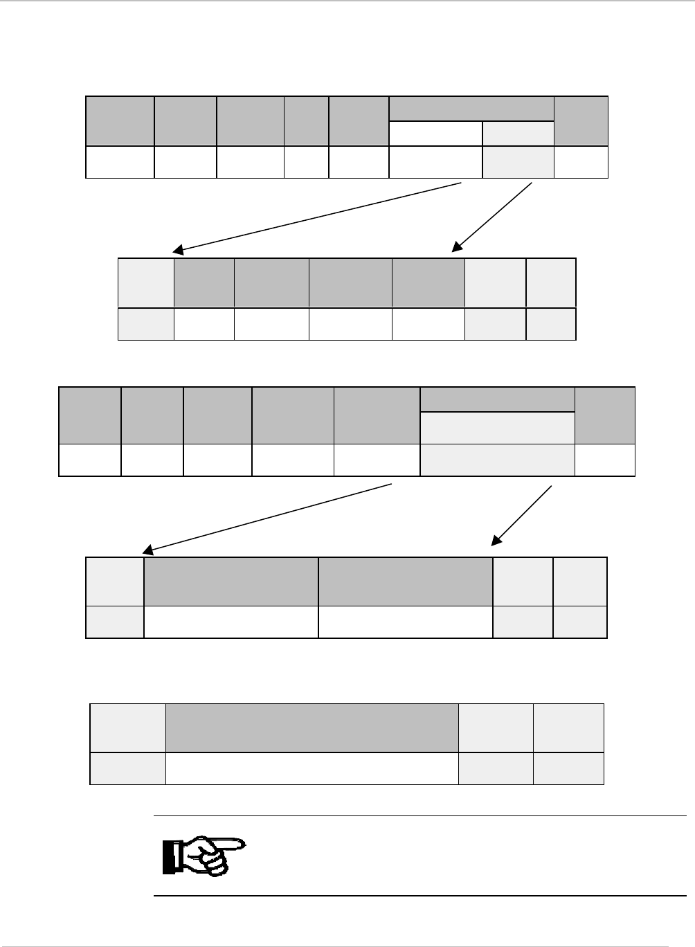
Response Packet Format
Standard reader Response Packet Format (See Section 3.1)
ISO Response
Data
Header Packet
Length Node
Address Response
Flags Command Checksum
‘01hex’LSB MSB LSB MSB Flags ‘60hex’
Data
bytes
0 - ‘m’ Byte 1 Byte 2
1 byte 2 bytes 2 bytes 1 byte 1 byte ‘m’ bytes 2 bytes
Response Packet Description
Field Length Description
Header 1 byte Defines the start of the packet (01hex).
Packet
Length 2 bytes Defines the length of the packet, including checksum.
Node
Address 2 bytes Defines the Node address of the reader.
Response
Flags 1 byte Defines the response of the reader to the request. Bit 4 defines the
error status; a set value indicates that an error has occurred. (Other
values reserved for future use)
Command 1 byte Defines the command that the reader executed (60hex for ISO 15693-3
commands)
Data 0-m
bytes Defines the data returned by the reader in response to a command.
Checksum 2 bytes Byte 1 is an XOR checksum of all elements from the header to the
last byte of the data field. Byte 2 is calculated as (FFhex) XOR (byte 1)
September 2001 S6350 Reader Reference Guide
30
3.2.3.3 Mandatory Commands
The data packet from the host to the reader is known as the request and the reply from the
reader to the host as the response. The host is always the primary station and initiates all
communication sequences. These consist of request/response pairs where the host waits for a
response before continuing. All ISO/IEC 15693-3 command request packets are contained
within the standard reader command request packet format. In all cases, reader command 60hex
is used to pass through ISO 15693 Part 3 commands to the reader.
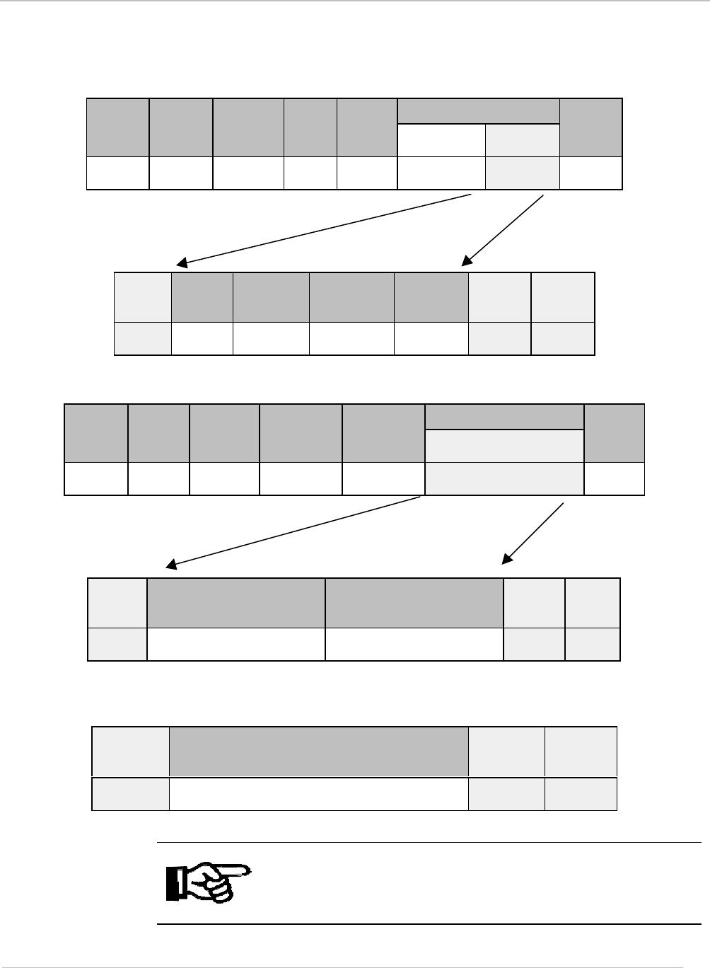
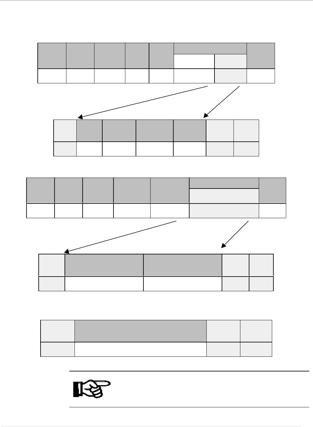
Inventory: Command Code (01hex)
ISO Inventory Request Command Packet ISO Command DataHeader Packet
Length Node
Address Cmd
Flag Cmd
Config. Byte Data
Check
-sum
‘01hex’2 bytes 2 bytes 1
byte ‘60
hex
’Byte 0 bytes
1 - n 2
bytes
ISO Inventory Request Format
SOF Flags Inventory
Command Opt.
AFI Mask
Length Mask
Value CRC16 EOF
Not
Used 1
byte ‘O1hex’1
byte 1 byte 0 - 7
bytes Not
Used Not
Used
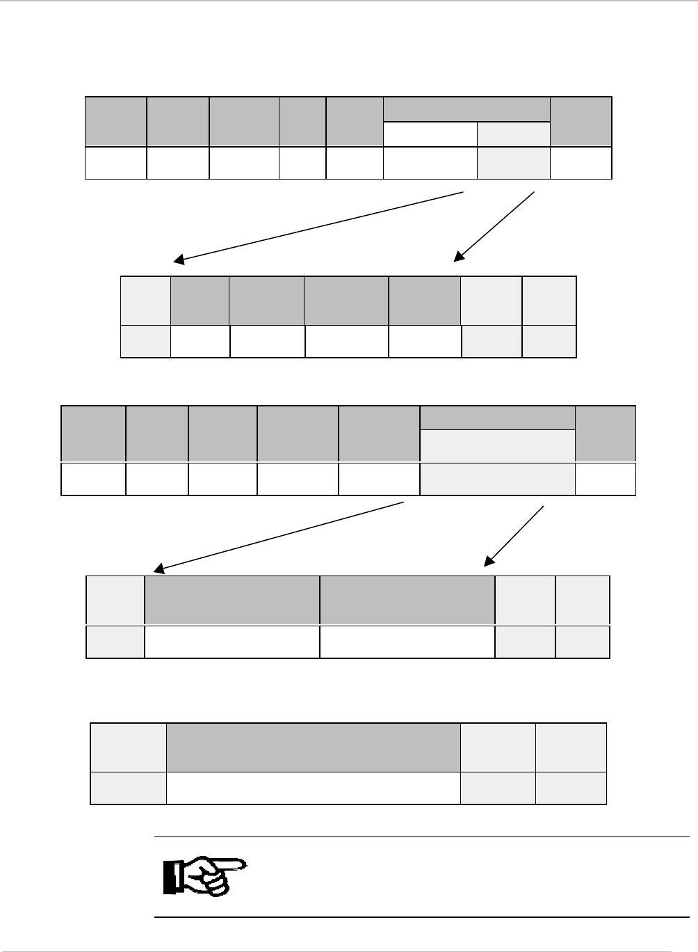
ISO Inventory Response Packet
The inventory response packet format, while complying with ISO 15693, is unique to the
reader reader and is described within the following illustrations. All other ISO 15693 packet
responses contain ISO 15693 data as detailed within ISO/IEC FDIS 15693-3.
ISO Response DataHeader Packet
Length Node
Address Response
Flags Command
Data
Check
sum
‘01hex’2 bytes 2 bytes 1 byte ‘60hex’bytes
0 - m 2 bytes
ISO Inventory Response Format
SOF Valid Data
Flags Collision
Flags 80-bit response to
Inventory Command Etc… CRC16 EOF
Not
Used 2 bytes
LSB/MSB 2 bytes
LSB/MSB Data returned from 1st
valid time slot Etc… Not
Used Not
Used

September 2001 S6350 Reader Reference Guide
31
Valid Data & Collision Flags
Valid Data Flags: This 16-bit field corresponds to whether valid data was received in the 16
possible Time Slots. Bits 0 to 7 of the LSB respectively correspond to Time Slots 1 to 8,
while bits 0 to 7 of the MSB correspond to Time Slots 9 to 16 respectively. A set bit
corresponds to valid data being received in that particular Time slot.
Collision Flags: This 16-bit field corresponding to whether a collision occurred in the 16
possible Time Slots. Bits 0 to 7 of the LSB respectively correspond to Time Slots 1 to 8,
while bits 0 to 7 of the MSB correspond to Time Slots 9 to 16 respectively. A set bit
corresponds to a collision being detected in that particular Time Slot.
Note:
It is possible to issue the Inventory Command for just 1 Time Slot
instead of 16. In this case, the preceding packet structure is still
valid; the required Valid Data flag and Collision flag reside in bit 0
of the LSB of their respective fields. It follows that issuing the
Inventory Command for a single Time Slot will result in a
maximum of one 80-bit response being returned
If both a Valid Data flag and its corresponding Collision flag are
both clear then this indicates that no transponder was detected for
that particular Time Slot.
Starting from Time Slot 1 and progressing to Time Slot 16, for each
Time Slot where a transponder was successfully read (without
collision), its 80-bit data is appended to the Data section of the
message packet.
September 2001 S6350 Reader Reference Guide
32
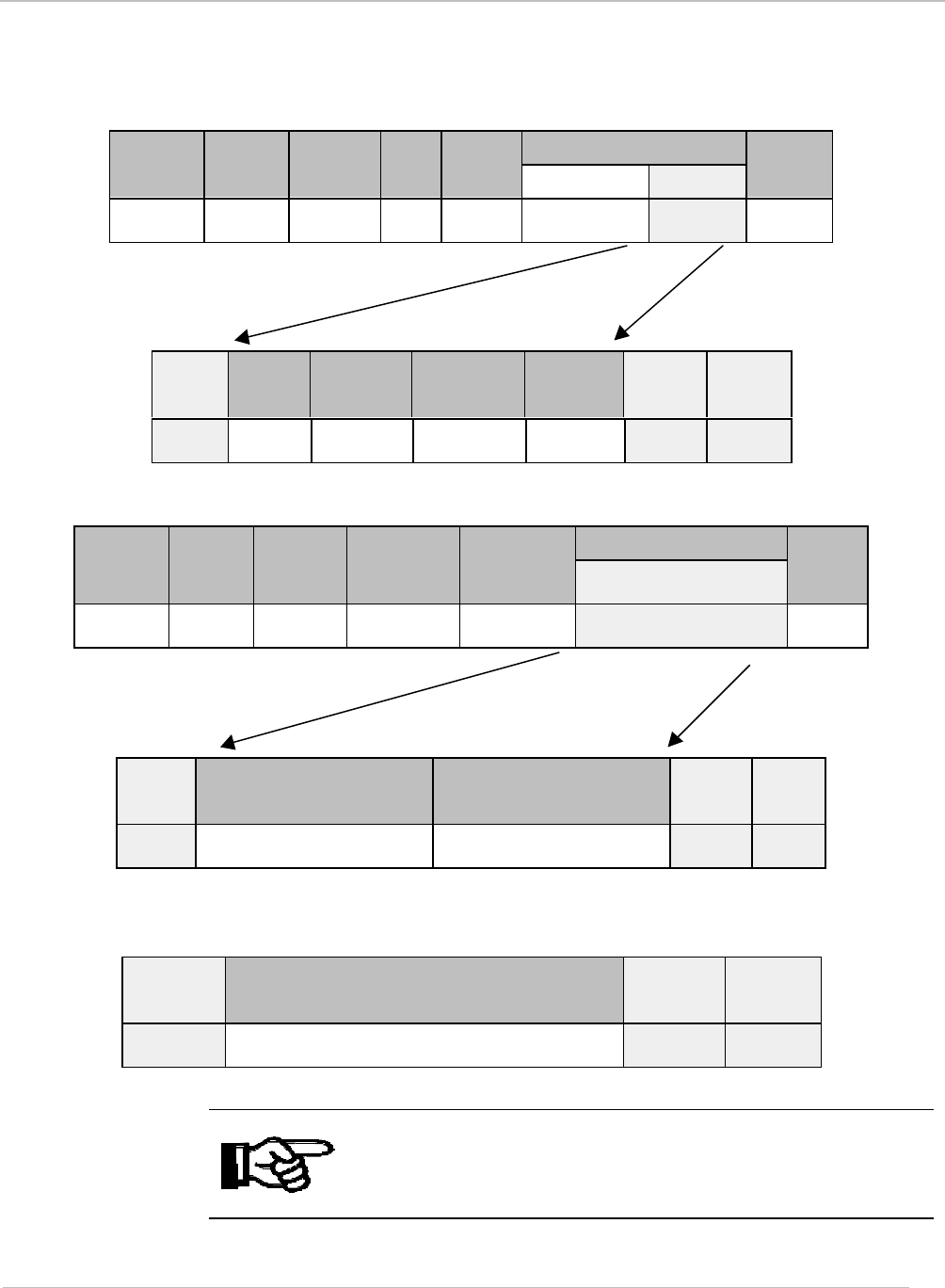
ISO Stay Quiet Request Command Packet: Command Code (02hex)
Upon receipt of the Stay Quiet command, the ISO tag will enter the quiet state and will not
initiate a response. Note: There is no response to the Stay Quiet command.
The Stay Quiet command is always executed in the Addressed mode:
Select_flag set to 0
Addressed_flag set to 1
ISO Command DataHeader Packet
Length Node
Address Cmd
Flag Cmd
Config. Byte Data
Check
-sum
‘01hex’2 bytes 2 bytes 1
byte ‘60hex’Byte 0 bytes
1 - n 2
bytes
ISO Stay Quiet Request Format
SOF Flags Stay Quiet
Command UID CRC16 EOF
Not
Used 1 byte ‘O2hex’8 bytes Not
Used Not
Used
3.2.3.4 Optional Commands
Read Single Block: Command Code (20hex)
ISO Read Single Block Request Command Packet ISO Command DataHeader Packet
Length Node
Address Cmd
Flag Cmd
Config.
Byte Data
Check
-sum
‘01hex’2 bytes 2 bytes 1
byte ‘60hex’Byte 0 bytes
1 - n 2
bytes
ISO Request Format
SOF Flags Read
Single
Block
UID Block
number CRC16 EOF
Not
Used 1 byte ‘20hex’8 bytes 1 byte Not
Used Not
Used
September 2001 S6350 Reader Reference Guide
33
ISO Read Single Block Response Packet
ISO Response DataHeader Packet
Length Node
Address Response
Flags Command
Data
Check
sum
‘01hex’2 bytes 2 bytes 1 byte ‘60hex’bytes
0 - m 2 bytes
Response when Error_flag is set
SOF Flags Error Code CRC16 EOF
Not
Used 1 byte 1 byte Not
Used Not
Used
OR
Response when Error_flag is not set
SOF Flags Block Security
status Data CRC16 EOF
Not
Used 1 byte 1 byte Block length Not
Used Not
Used
September 2001 S6350 Reader Reference Guide
34
ISO Write Single Block: Command Code (21hex)
ISO Write Single Block Request Command Packet
ISO Command DataHeader Packet
Length Node
Address Cmd
Flag Cmd
Config.
Byte Data
Check-
sum
‘01hex’2 bytes 2 bytes 1
byte ‘60hex’Byte 0 bytes
1 - n 2 bytes
ISO Request Format
SOF *Flags Write
Single
Block
UID Block
number CRC16 EOF
Not
Used 1 byte ‘21hex’8 bytes 1 byte Not
Used Not
Used
ISO Write Single Block Response Packet
ISO Response DataHeader Packet
Length Node
Address Response
Flags Command
Data
Check
sum
‘01hex’2 bytes 2 bytes 1 byte ‘60hex’bytes
1 - m 2 bytes
Response when Error_flag is set
SOF Flags Error Code CRC16 EOF
Not
Used 1 byte 1 byte Not
Used Not
Used
OR
Response when Error_flag is not set
SOF Flags CRC16 EOF
Not
Used 1 byte Not
Used Not
Used
Note:
* Bit 7 of the ISO 15693 protocol Option_Flag must be set to 1 for
all Write and Lock commands to respond properly.
September 2001 S6350 Reader Reference Guide
35
ISO Lock Block: Command Code (22hex)
ISO Lock Block Request Command Packet
ISO Command DataHeader Packet
Length Node
Address Cmd
Flag Cmd
Config. Byte Data
Check-
sum
‘01hex’2 bytes 2 bytes 1
byte ‘60hex’Byte 0 bytes
1 - n 2 bytes
ISO Request Format
SOF *Flags Lock
Block UID Block
number CRC16 EOF
Not
Used 1 byte ‘22hex’8 bytes 1 byte Not
Used Not
Used
ISO Lock Block Response Packet
ISO Response DataHeader Packet
Length Node
Address Response
Flags Command
Data
Check
sum
‘01hex’2 bytes 2 bytes 1 byte ‘60hex’bytes
1 - m 2 bytes
Response when Error_flag is set
SOF Flags Error Code CRC16 EOF
Not
Used 1 byte 1 byte Not
Used Not
Used
OR
Response when Error_flag is not set
SOF Flags CRC16 EOF
Not
Used 1 byte Not
Used Not
Used
Note:
* Bit 7 of the ISO 15693 protocol Option_Flag must be set to 1 for
all Write and Lock commands to respond properly.
September 2001 S6350 Reader Reference Guide
36
ISO Read Multiple Blocks: Command Code (23hex)
ISO Read Multiple Blocks Request Command Packet
ISO Command DataHeader Packet
Length Node
Address Cmd
Flag Cmd
Config.
Byte Data
Check-
sum
‘01hex’2 bytes 2 bytes 1
byte ‘60hex’Byte 0 bytes
1 - n 2 bytes
ISO Request Format
SOF Flags Read
Multiple
Blocks
UID 1st
Block
#
# of
blocks CRC1
6EOF
Not
Used 1 byte ‘23hex’8
bytes 1 byte 1 byte Not
Used Not
Used
ISO Read Multiple Blocks Response Packet
ISO Response DataHeader Packet
Length Node
Address Response
Flags Command
Data
Check
sum
‘01hex’2 bytes 2 bytes 1 byte ‘60hex’bytes
1 - m 2
bytes
Response when Error_flag is set
SOF Flags Error Code CRC16 EOF
Not
Used 1 byte 1 byte Not
Used Not
Used
OR
Response when Error_flag is not set
SOF Flags Block
Security
Status
Data CRC16 EOF
Not
Used 1 byte 1 byte Block length Not
Used Not
Used
Repeat as needed
September 2001 S6350 Reader Reference Guide
37
ISO Write AFI: Command Code (27hex)
ISO Write AFI Request Command Packet
ISO Command DataHeader Packet
Length Node
Address Cmd
Flag Cmd
Config. Byte Data
Chec
k-sum
‘01hex’2 bytes 2 bytes 1
byte ‘60hex’Byte 0 bytes
1 - n 2
bytes
ISO Request Format
SOF *Flags Write
AFI UID AFI CRC16 EOF
Not
Used 1 byte ‘27hex’8 bytes 1 byte Not
Used Not
Used
ISO Write AFI Response Packet
ISO Response DataHeader Packet
Length Node
Address Response
Flags Command
Data
Check
sum
‘01hex’2 bytes 2 bytes 1 byte ‘60hex’bytes
1 - m 2 bytes
Response when Error_flag is set
SOF Flags Error Code CRC16 EOF
Not
Used 1 byte 1 byte Not
Used Not
Used
OR
Response when Error_flag is not set
SOF Flags CRC16 EOF
Not
Used 1 byte Not
Used Not
Used
Note:
* Bit 7 of the ISO 15693 protocol Option_Flag must be set to 1 for
all Write and Lock commands to respond properly.
September 2001 S6350 Reader Reference Guide
38
ISO Lock AFI: Command Code (28hex)
ISO Lock AFI Request Command Packet ISO Command DataHeader Packet
Length Node
Address Cmd
Flag Cmd
Config.
Byte Data
Check-
sum
‘01hex’2 bytes 2 bytes 1
byte ‘60hex’Byte 0 bytes
1 - n 2 bytes
ISO Request Format
SOF *Flags Lock
AFI UID AFI CRC16 EOF
Not
Used 1 byte ‘28hex’8 bytes 1 byte Not
Used Not
Used
ISO Lock AFI Response Packet
ISO Response DataHeader Packet
Length Node
Address Response
Flags Command
Data
Check
sum
‘01hex’2 bytes 2 bytes 1 byte ‘60hex’bytes
1 - m 2 bytes
Response when Error_flag is set
SOF Flags Error Code CRC16 EOF
Not
Used 1 byte 1 byte Not
Used Not
Used
OR
Response when Error_flag is not set
SOF Flags CRC16 EOF
Not
Used 1 byte Not
Used Not
Used
Note:
* Bit 7 of the ISO 15693 protocol Option_Flag must be set to 1 for
all Write and Lock commands to respond properly.
September 2001 S6350 Reader Reference Guide
39
ISO Write DSFID: Command Code (29hex)
ISO Write DSFID Request Command Packet
ISO Command DataHeader Packet
Length Node
Address Cmd
Flag Cmd
Config. Byte Data
Check-
sum
‘01hex’2 bytes 2 bytes 1
byte ‘60hex’Byte 0 bytes
1 - n 2 bytes
ISO Request Format
SOF *Flags Write
DSFID UID DSFID CRC16 EOF
Not
Used 1 byte ‘29hex’8 bytes 1 byte Not
Used Not
Used
ISO Write DSFID Response Packet
ISO Response DataHeader Packet
Length Node
Address Response
Flags Command
Data
Check
sum
‘01hex’2 bytes 2 bytes 1 byte ‘60hex’bytes
1 - m 2 bytes
Response when Error_flag is set
SOF Flags Error Code CRC16 EOF
Not
Used 1 byte 1 byte Not
Used Not
Used
OR
Response when Error_flag is not set
SOF Flags CRC16 EOF
Not
Used 1 byte Not
Used Not
Used
Note:
* Bit 7 of the ISO 15693 protocol Option_Flag must be set to 1 for
all Write and Lock commands to respond properly.
September 2001 S6350 Reader Reference Guide
40
ISO Lock DSFID: Command Code (2Ahex)
ISO Lock DSFID Request Command Packet
ISO Command DataHeader Packet
Length Node
Address Cmd
Flag Cmd
Config.
Byte Data
Check-
sum
‘01hex’2 bytes 2 bytes 1
byte ‘60hex’Byte 0 bytes
1 - n 2 bytes
ISO Request Format
SOF *Flags Lock
DSFID UID CRC16 EOF
Not
Used 1 byte ‘2Ahex’8 bytes Not
Used Not
Used
ISO Lock DSFID Response Packet
ISO Response DataHeader Packet
Length Node
Address Response
Flags Command
Data
Check
sum
‘01hex’2 bytes 2 bytes 1 byte ‘60hex’bytes
1 - m 2 bytes
Response when Error_flag is set
SOF Flags Error Code CRC16 EOF
Not
Used 1 byte 1 byte Not
Used Not
Used
OR
Response when Error_flag is not set
SOF Flags CRC16 EOF
Not
Used 1 byte Not
Used Not
Used
Note:
* Bit 7 of the ISO 15693 protocol Option_Flag must be set to 1 for
all Write and Lock commands to respond properly.
September 2001 S6350 Reader Reference Guide
41
ISO Get Multiple Block Security Status: Command Code (2Chex)
ISO Get Multiple Block Security Status Request Command Packet
ISO Command DataHeader Packet
Length Node
Address Cmd
Flag Cmd
Config.
Byte Data
Check-
sum
‘01hex’2 bytes 2 bytes 1
byte ‘60hex’Byte 0 bytes
1 - n 2 bytes
ISO Request Format
SOF Flags Get Multiple
Block Security
Status
UID 1st
Block
#
# of
Blocks CRC16 EOF
Not
Used 1 byte ‘2Chex’8
bytes 8
bytes Not
Used Not
Used
ISO Get Multiple Block Security Status Response Packet
ISO Response DataHeader Packet
Length Node
Address Response
Flags Command
Data
Check
sum
‘01hex’2 bytes 2 bytes 1 byte ‘60hex’bytes
1 - m 2 bytes
Response when Error_flag is set
SOF Flags Error Code CRC16 EOF
Not
Used 1 byte 1 byte Not
Used Not
Used
OR
Response when Error_flag is not set
SOF Flags Block Security Status CRC16 EOF
Not
Used 1 byte 1 byte Not
Used Not
Used
Repeat as needed

42
Regulatory and Warranty Notices
Topic Page
4.1 FCC Conformity.........................................................................................43
4.2 ETSI Conformity........................................................................................43
4.3 CE Conformity...........................................................................................43
4.4 Warranty and Liability ................................................................................43
Chapter 4

July 2001 Series 6350 Reader Reference Guide
43
4.1 FCC Conformity
The S 6350 reader is an intentional radiator. The transmitter portion operates at 13.56 MHz and
is subject to FCC Part 15, Subpart C, “Intentional Radiator,” paragraph 15.225 (13.553-
13.567MHz). Radiated emissions from the device are subject to the limits in Section 15.209 of
the Rules outside of the 13.56 +/- 0.007 MHz band.
Note:
Any device or system incorporating the S 6350 reader, in full or in
part, needs to obtain FCC certification as part of the system within
which this reader unit resides. A system containing this product
may be operated only under an experimental license or final
approval issued by the relevant approval authority. Before any
such device or system can be marketed, an equipment
authorization must be obtained form the relevant approval
authority.
4.2 ETSI Conformity
Any device or system incorporating the S 6350 reader, in full or in part, may need to comply with
European Standard EN300330. It is the responsibility of each system integrator to have their
complete system tested and to obtain approvals as required from the local authorities before
operating or selling this system.
4.3 CE Conformity
Any device or system incorporating the S 6350 reader, in full or in part, may need to have a CE
Declaration of Conformity stating that it meets European EMC directive 99/5/EC. This must be
issued by the system integrator or user of such a system prior to marketing or operating it in the
European community.
4.4 Warranty and Liability
The "General Conditions of Sale and Delivery" of Texas Instruments Incorporated or a TI
subsidiary apply. Warranty and liability claims for defect products, injuries to persons and
property damages are void if they are the result of one or more of the following causes:
§ Improper use of the reader module.
§ Unauthorized assembly, operation and maintenance of the reader module.
§ Operation of the reader modules with defective and/or non-functioning safety and
protective equipment.
§ Failure to observe the instructions during transport, storage, assembly, operation,
maintenance and setting up of the reader modules.
§ Unauthorized changes to the reader modules.
§ Insufficient monitoring of the reader modules' operation or environmental conditions.
§ Improperly conducted repairs.
§ Catastrophes caused by foreign bodies and acts of God.

44
Downloading Data to FLASH Memory
The S 6350 Reader FLASH memory contains two areas: the application area for the Reader
application firmware and a boot-loader area for the boot-loader firmware. The boot-loader
memory is factory locked.
After a reset the boot-loader firmware runs the following sequence:
• Control registers are initialized
• IO ports are initialized
• Application memory is scanned and verified
• If the application memory checksums are valid then control is transferred to the
application memory
• If the checksums fail then the boot-loader takes control of the communications.
The boot-loader will only accept the following commands:
• Initiate FLASH Loader Command (D0 hex)
• Send Data to FLASH Command (D8hex)
• Read reader Version Command (F0hex)
The boot loader only operates at 57600 baud with 8 data bits, 1 start bit, 1 stop bit and no parity.
The application firmware will always accept the Initiate FLASH Loader Command (D0 hex).
When this command is received by the application firmware, control is transferred to the boot-
loader. If the boot-loader does not receive a Send Data to FLASH Command (D8hex) within 5
seconds of the Initiate FLASH Loader Command (D0 hex) then a system reset is generated.
The application firmware is provided in a single file and contains all the necessary checksums.
The file will always contain 29700 bytes of data.
The file must be sent to the reader in one session if any errors occur the whole file must be
resent. The file is sent in 225 segments, 132 bytes at a time (225 x 132 = 29700). Each segment
is sent using the Send Data to FLASH Command (D8hex). The 132 bytes of data are contained
in the data section of the packet.
Appendix A

45
Error Codes Code number Meaning
01hex Transponder not found
02hex Command not supported
03hex Packet BCC invalid
04hex Packet flags invalid for command
05hex General write failure
06hex Write failure due to locked block
07hex Transponder does not support function
0Fhex Undefined error
Appendix B