BandRich 35K899 RUGGEDIZED 4G LTE M2M & VEHICLE MOUNT ROTER User Manual BandLuxe FieldPerfect
BandRich Inc. RUGGEDIZED 4G LTE M2M & VEHICLE MOUNT ROTER BandLuxe FieldPerfect
UserManual.wiki
>
BandRich
>
35K899 User Manual
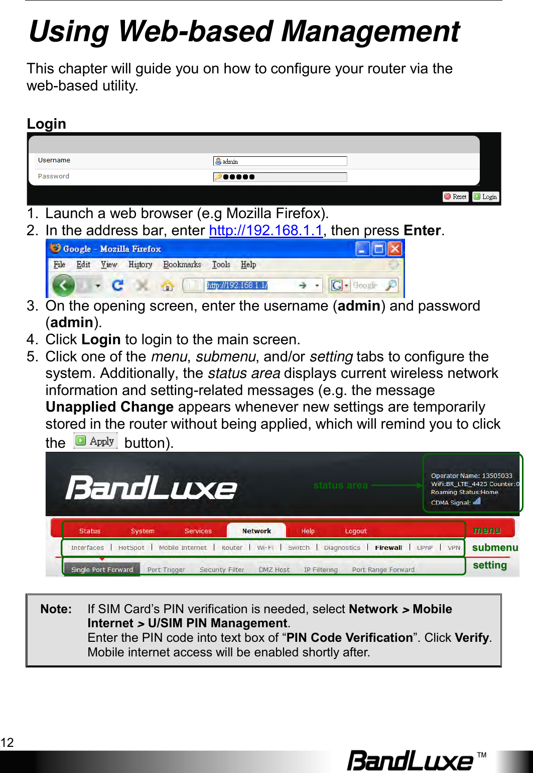
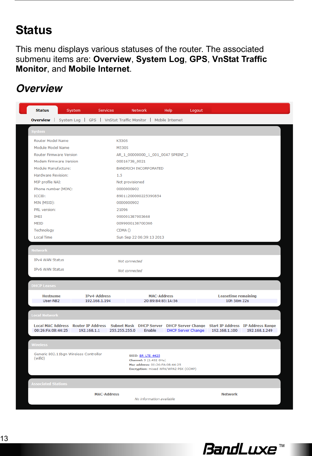
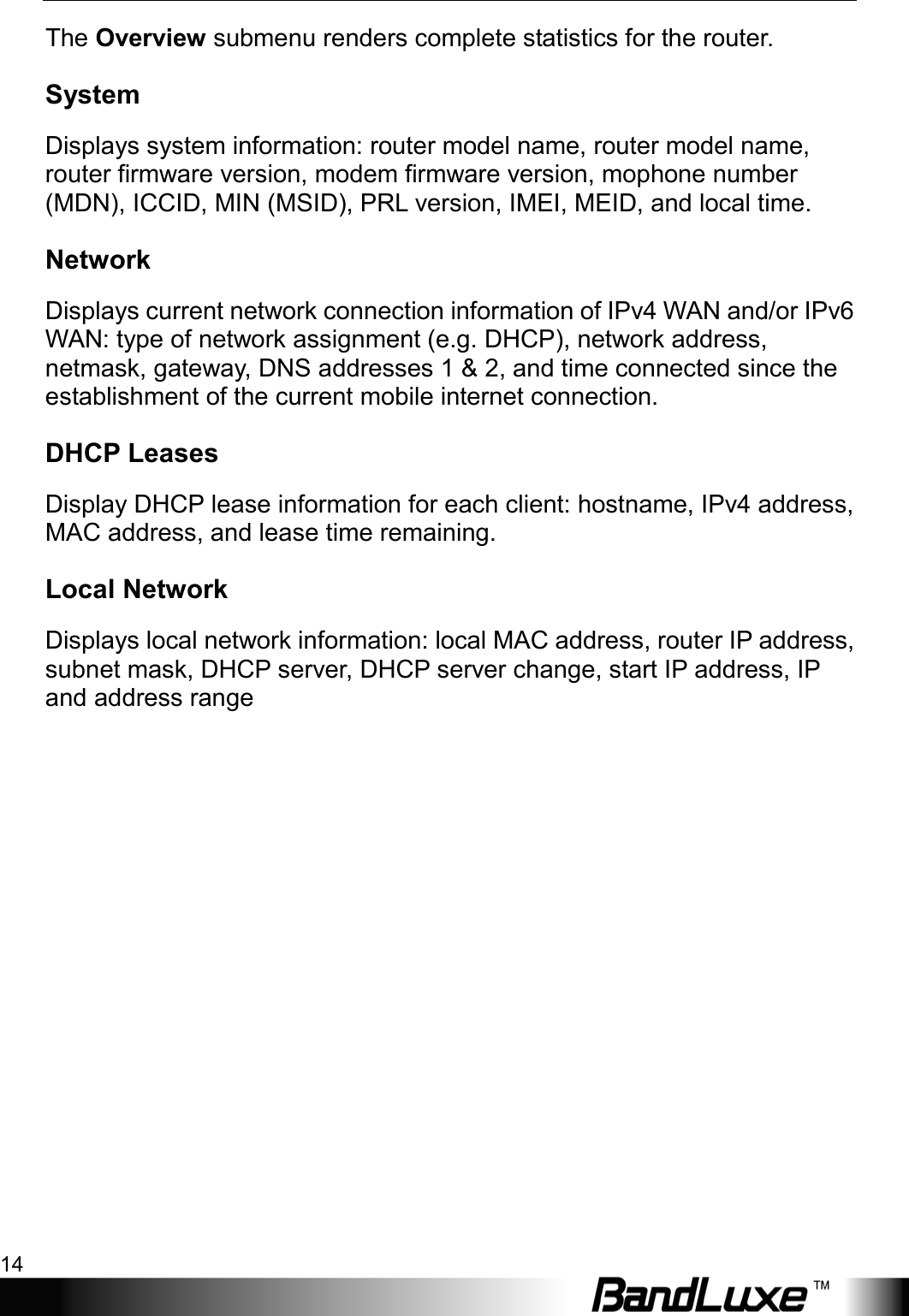
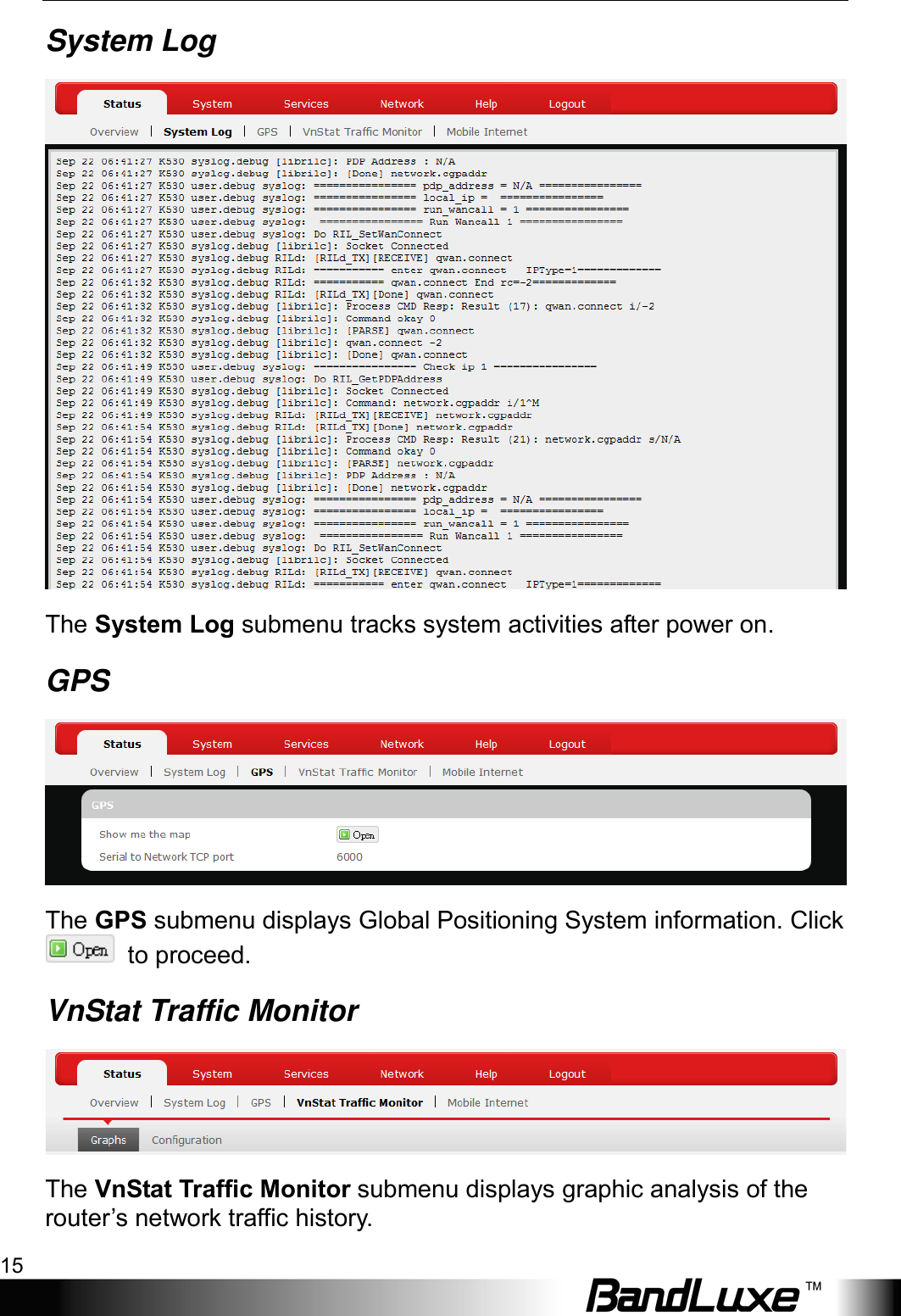
USERS MANUAL
Navigation menu
Upload a User Manual
Namespaces
Wiki Guide
HTML
PDF
Info
Views
User Manual
Discussion / Help
Navigation
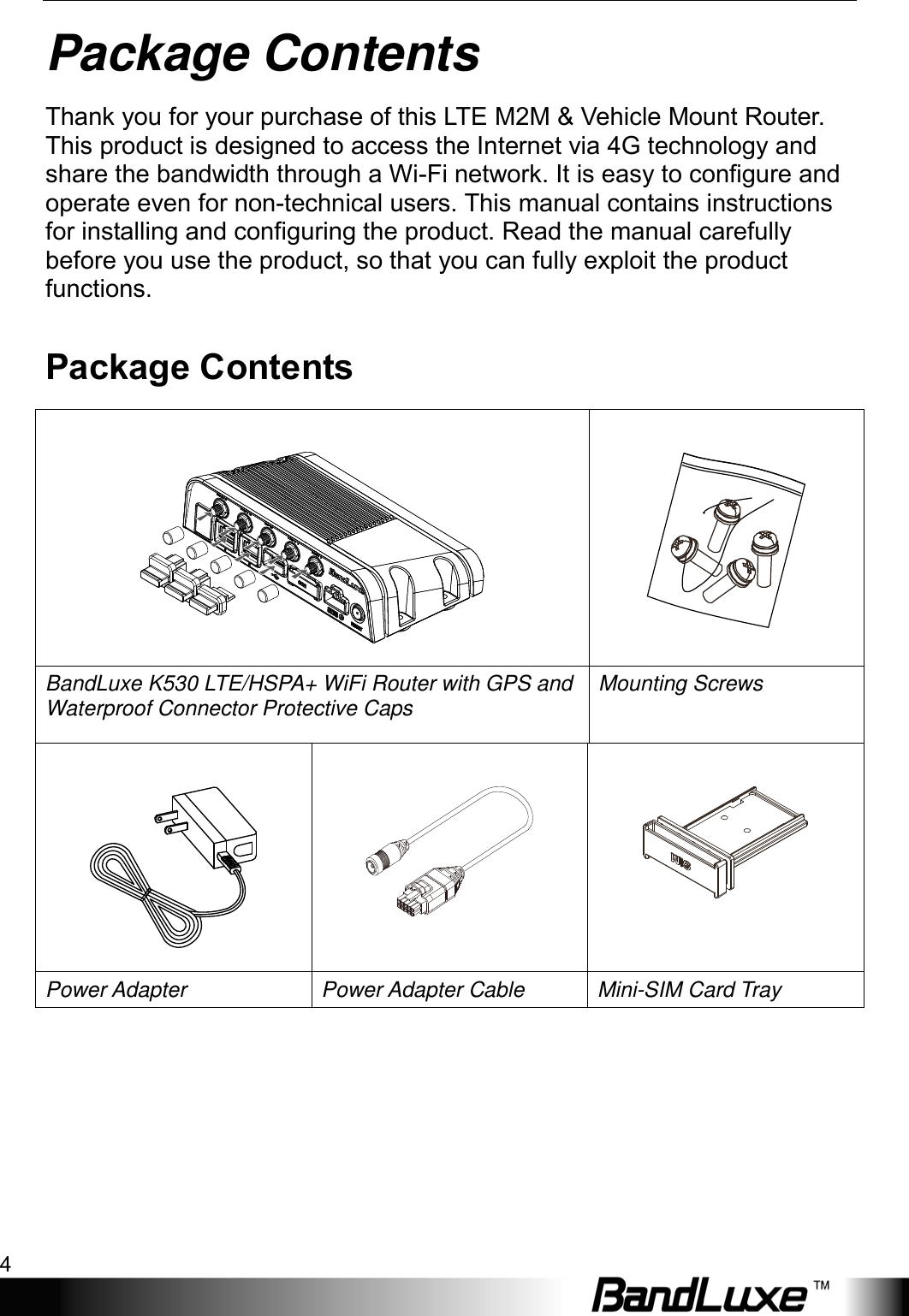
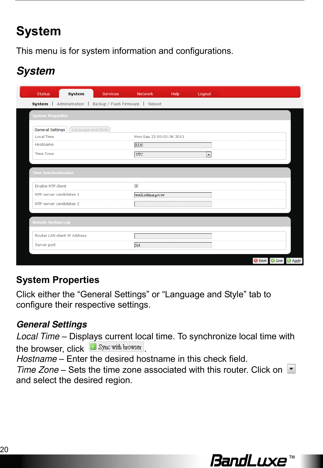
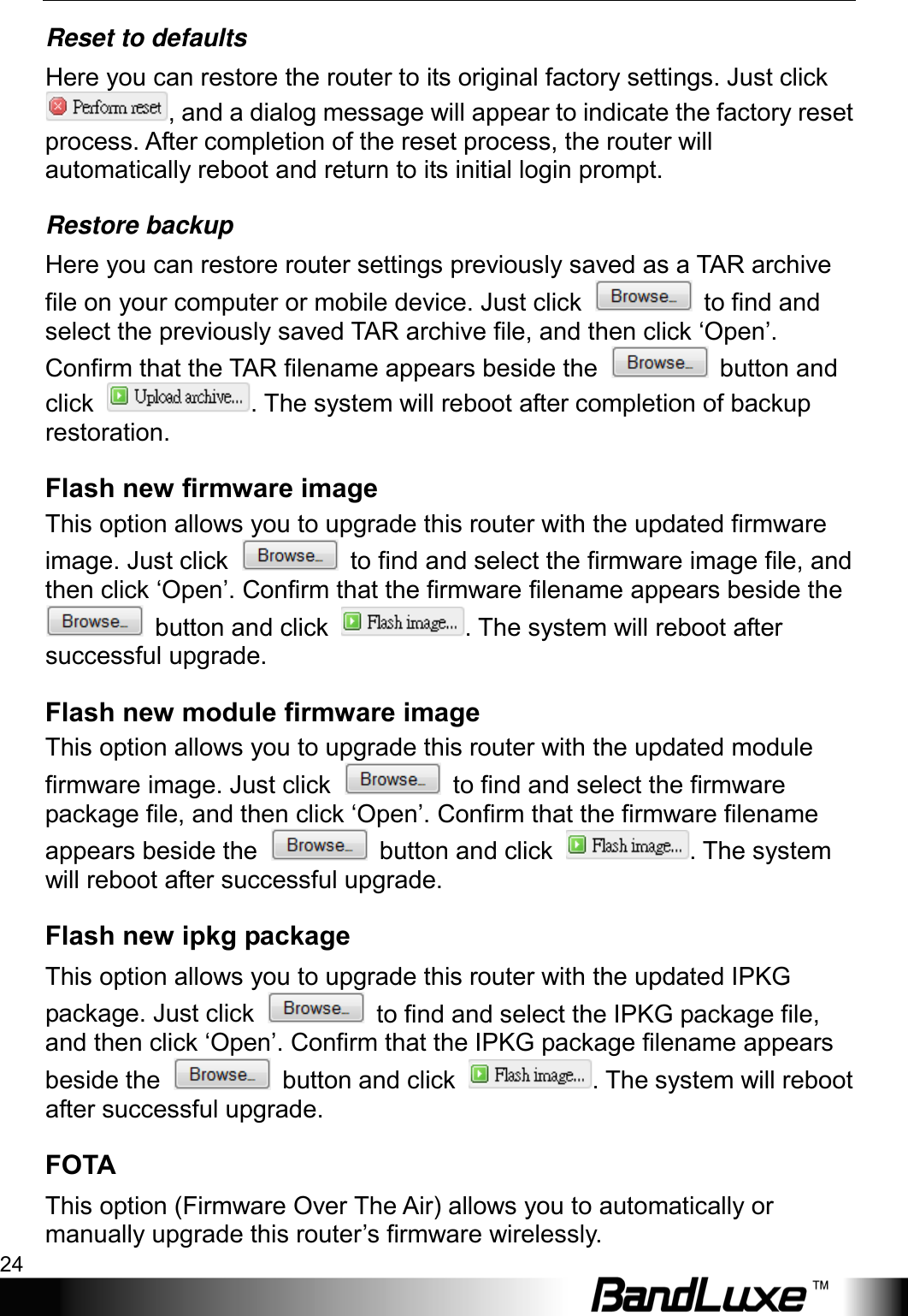
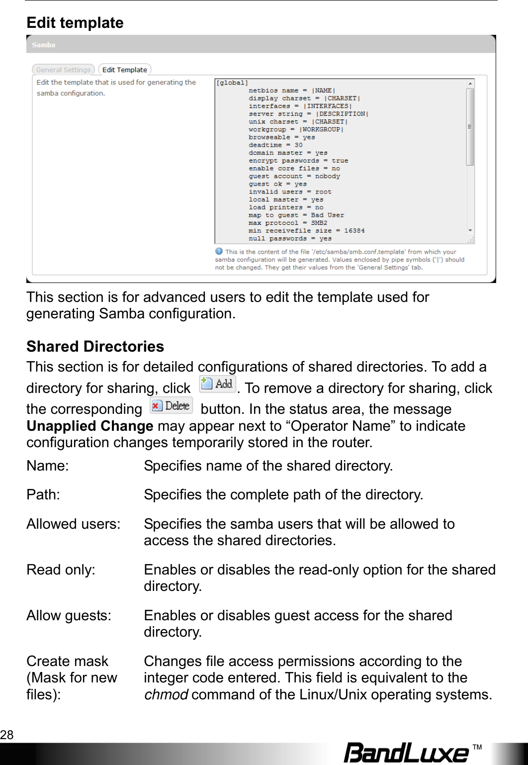
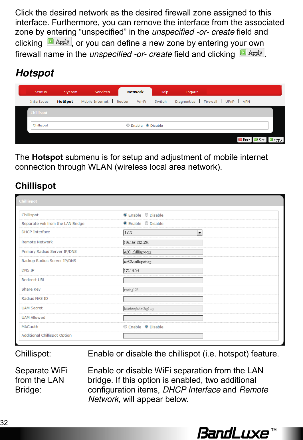
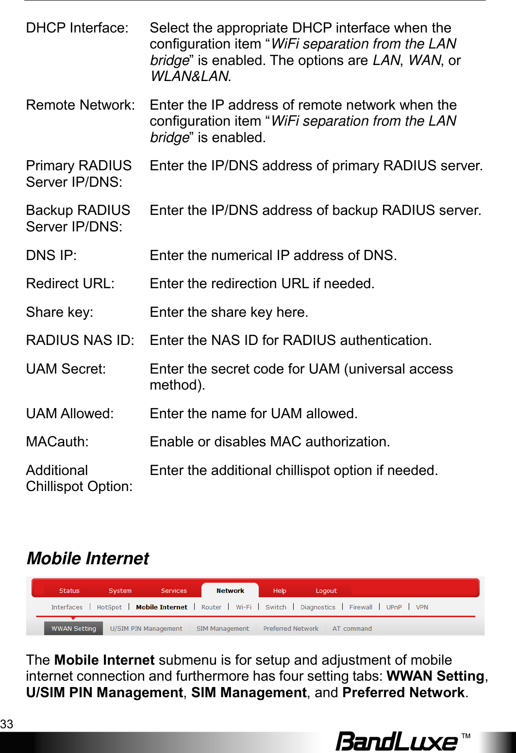
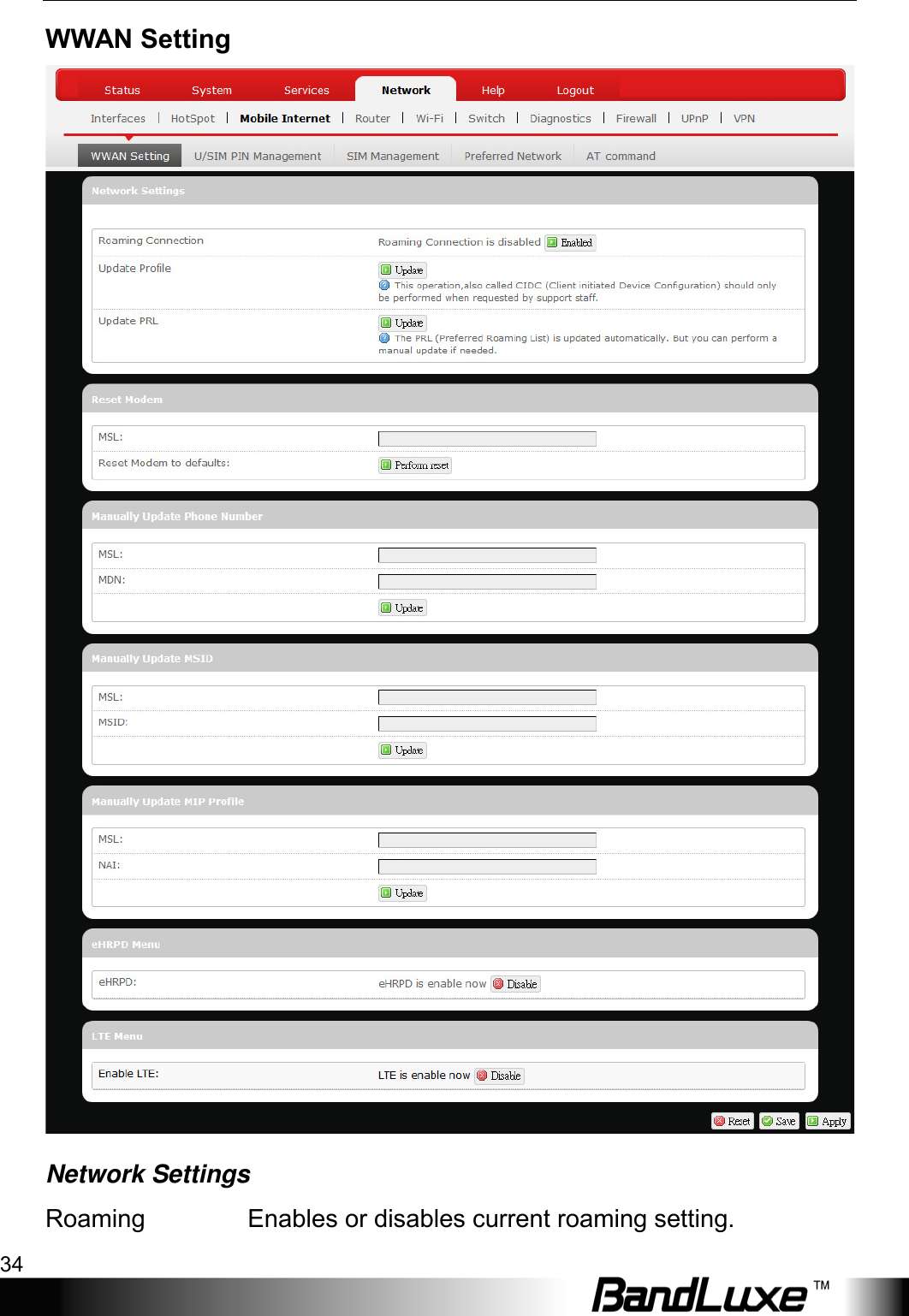
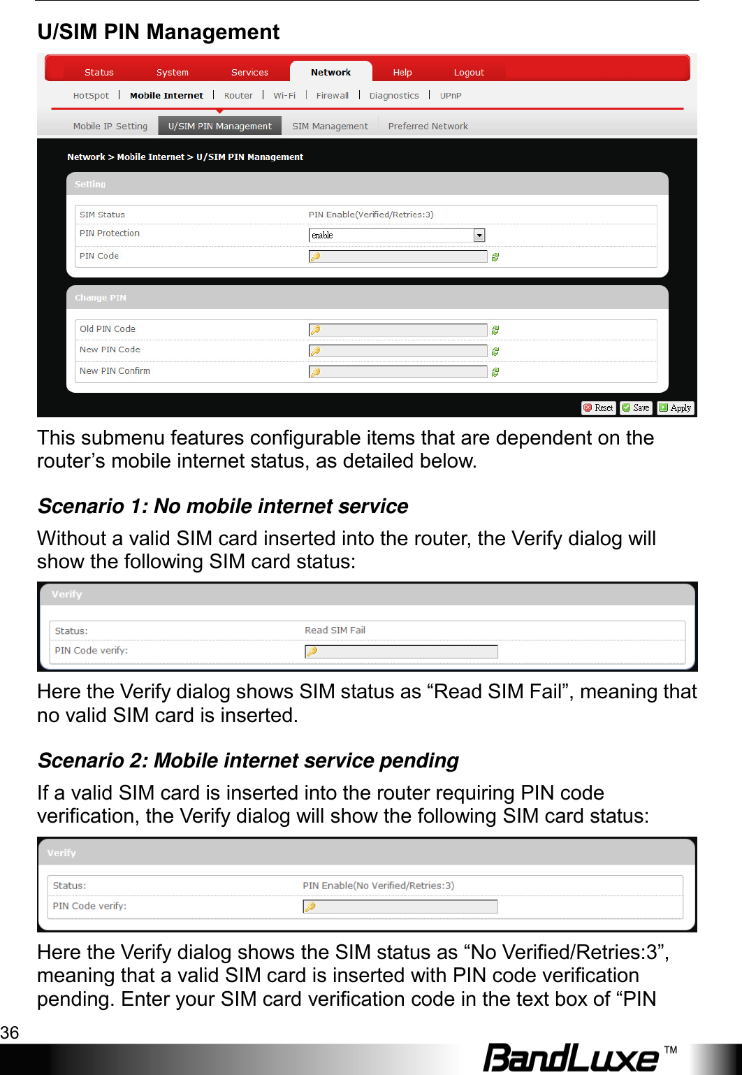
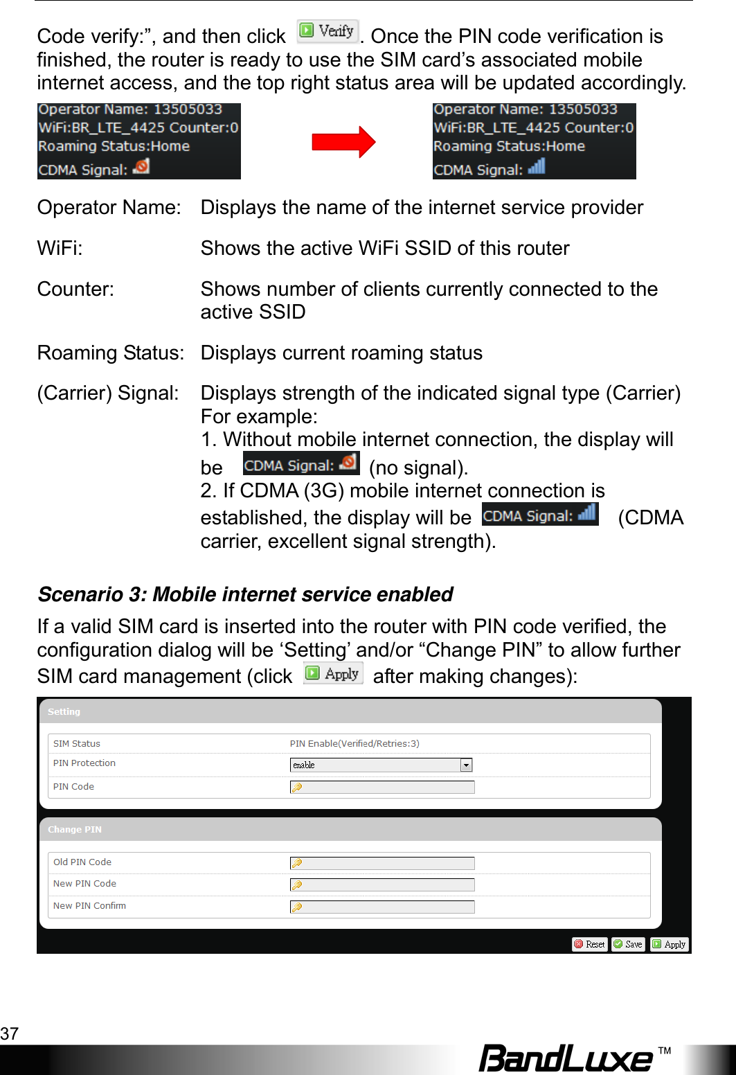
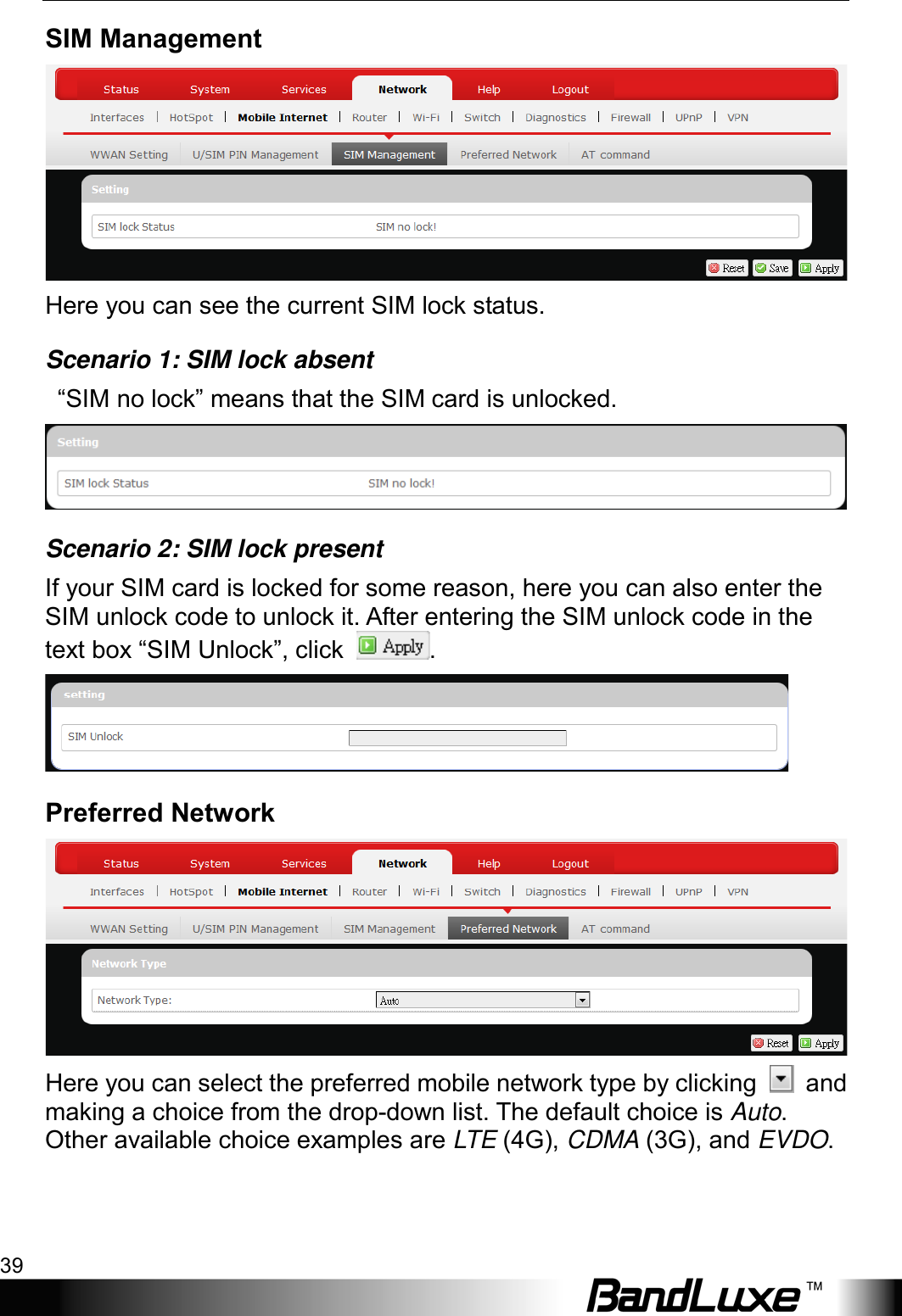
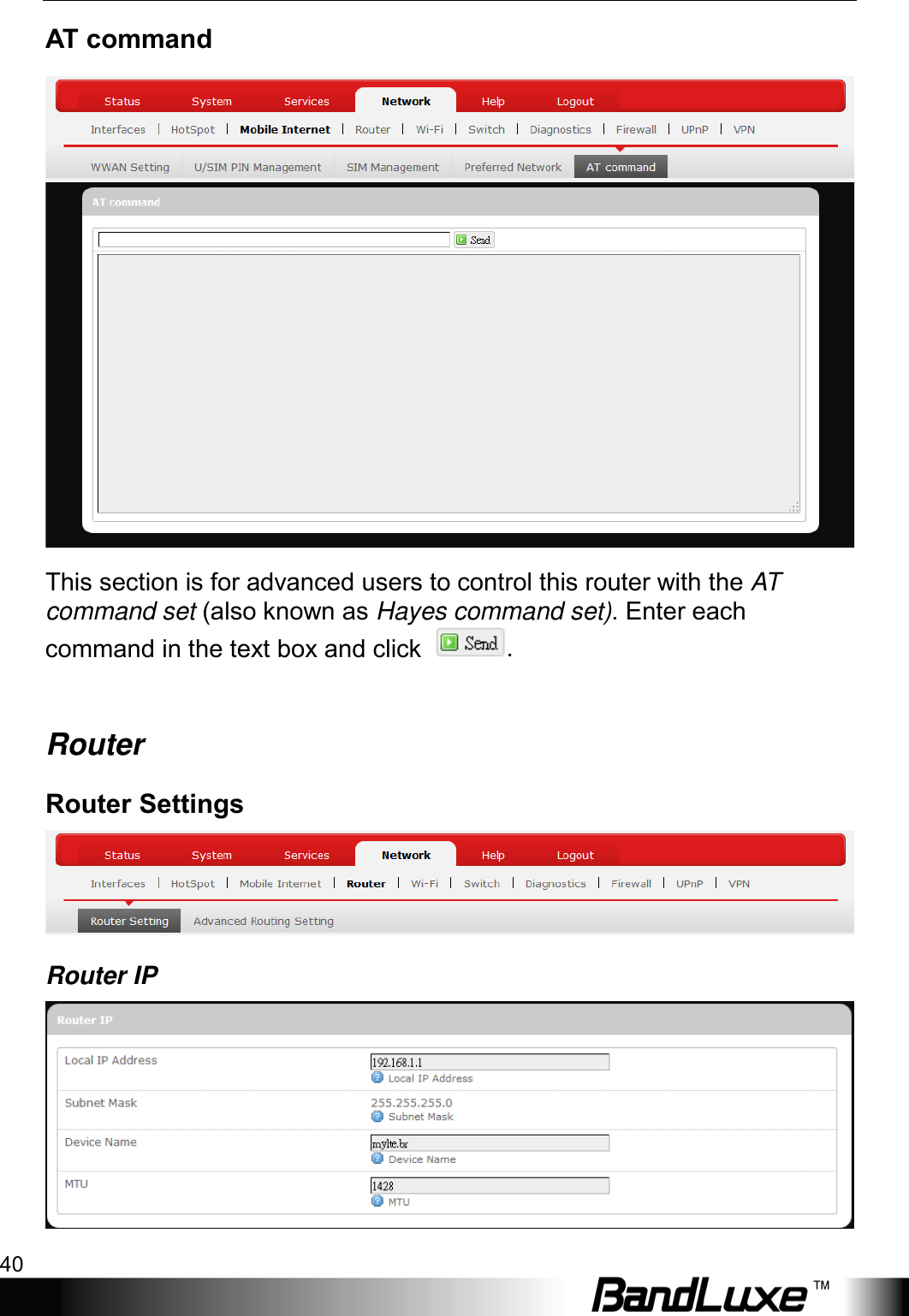
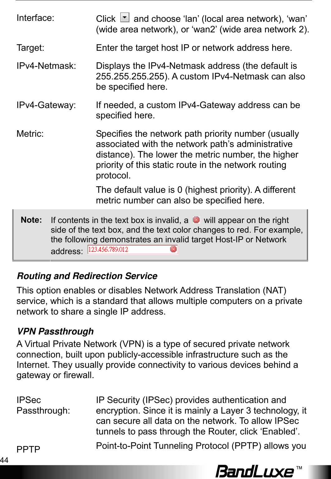
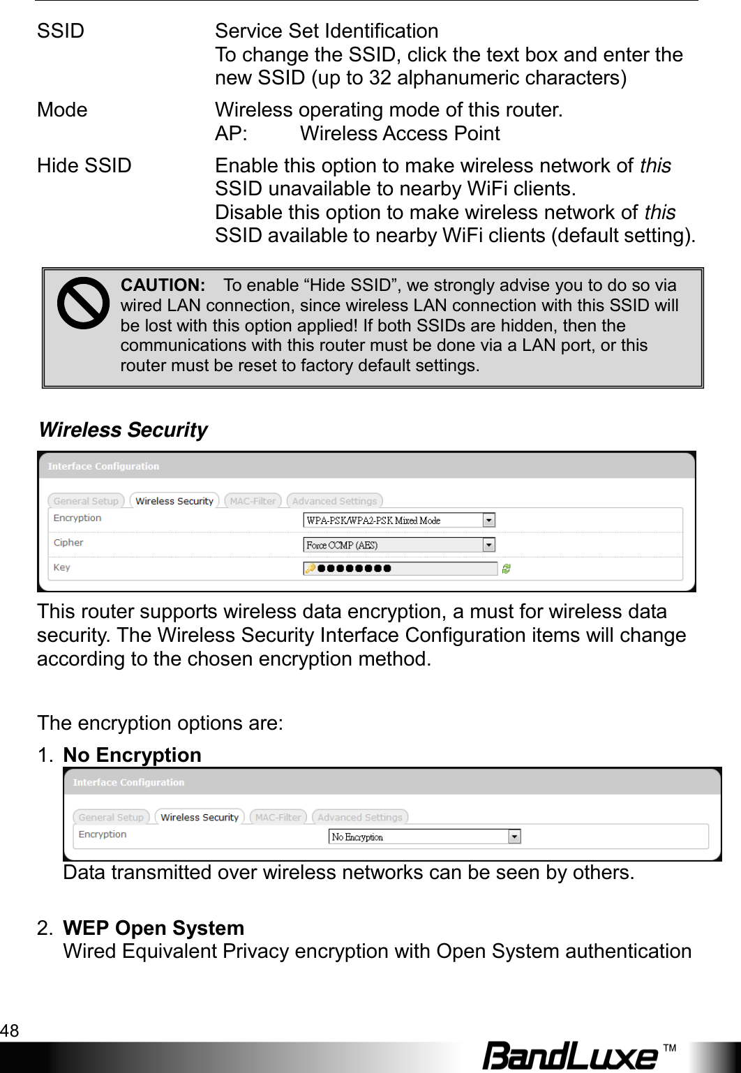
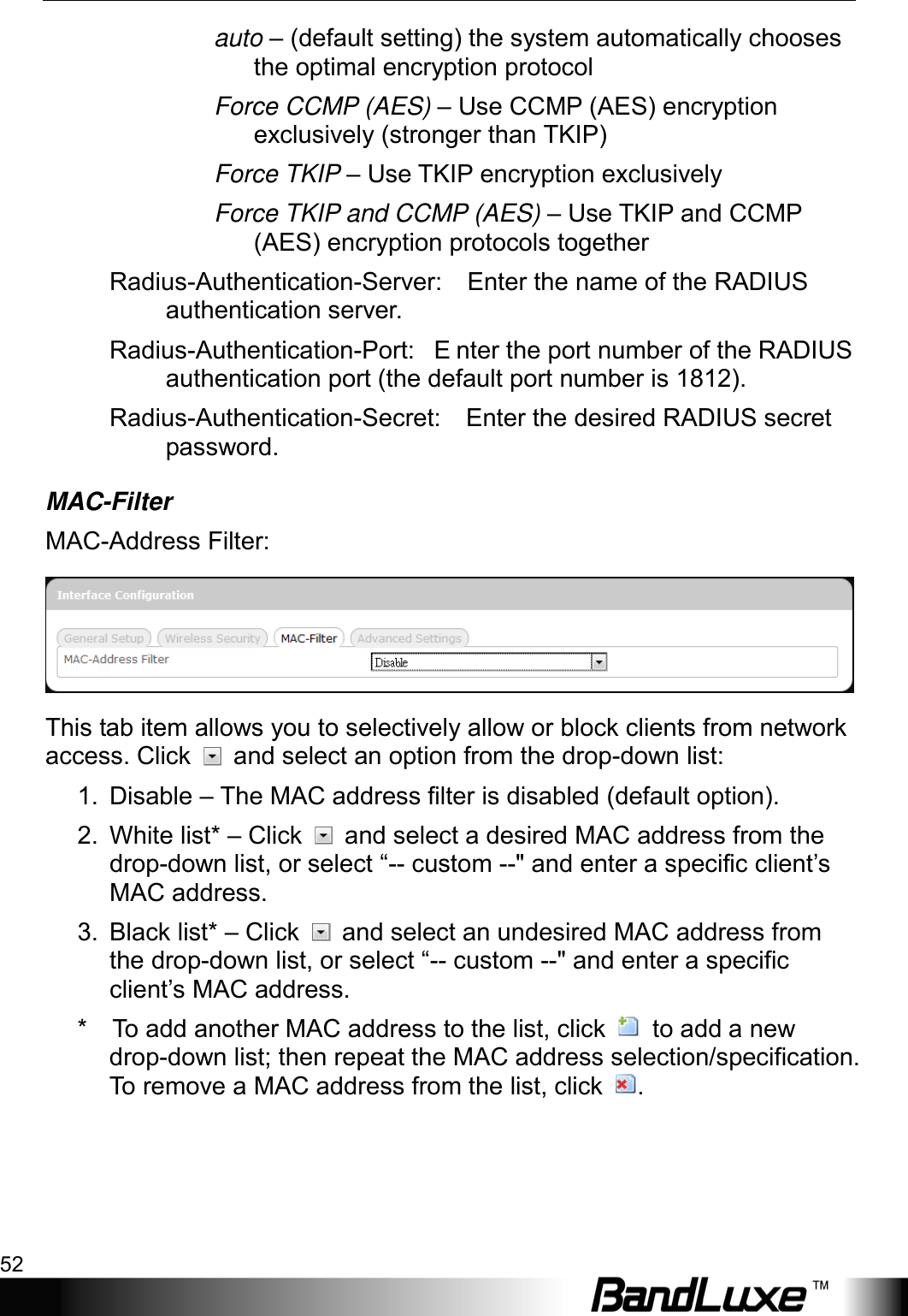
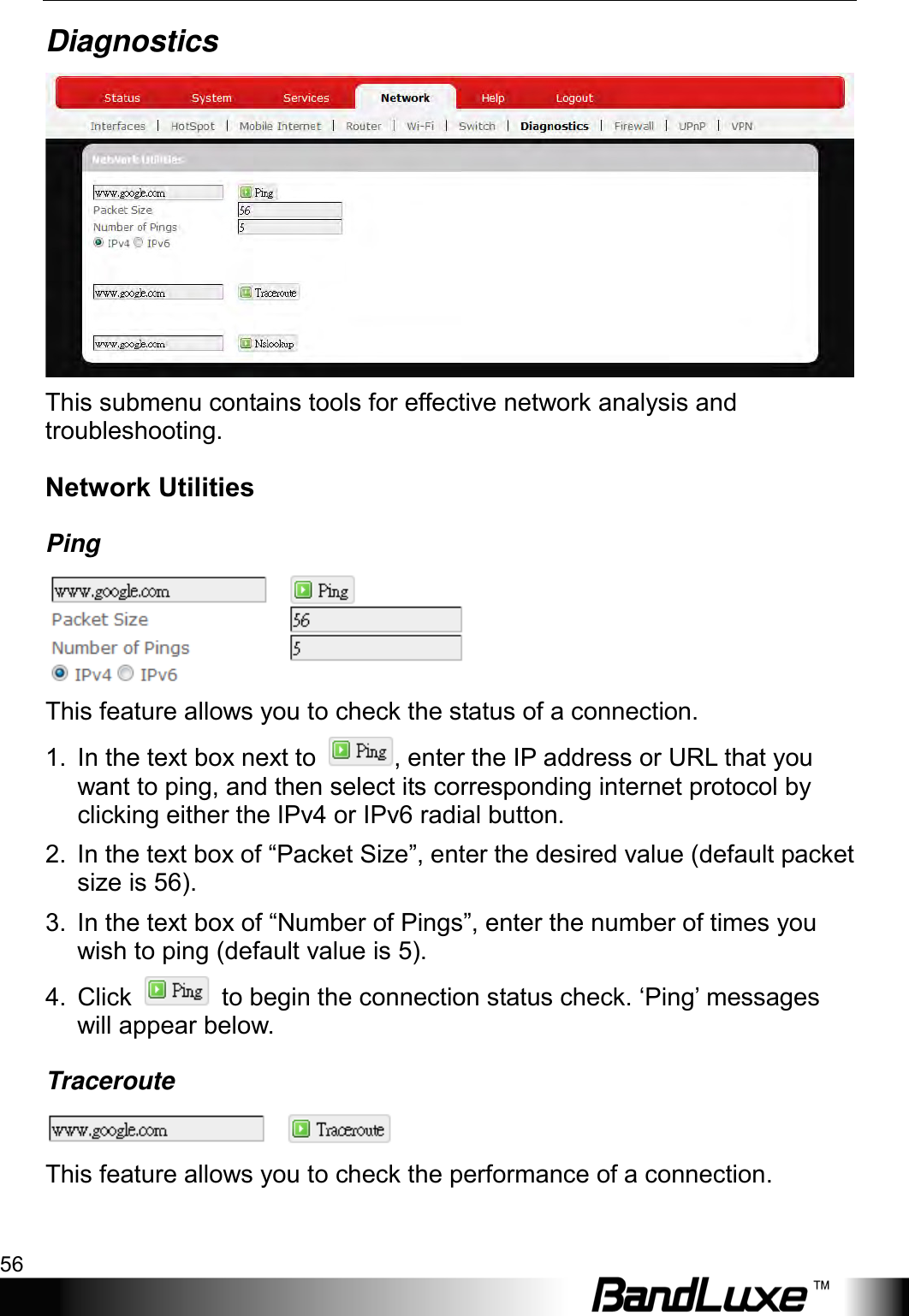
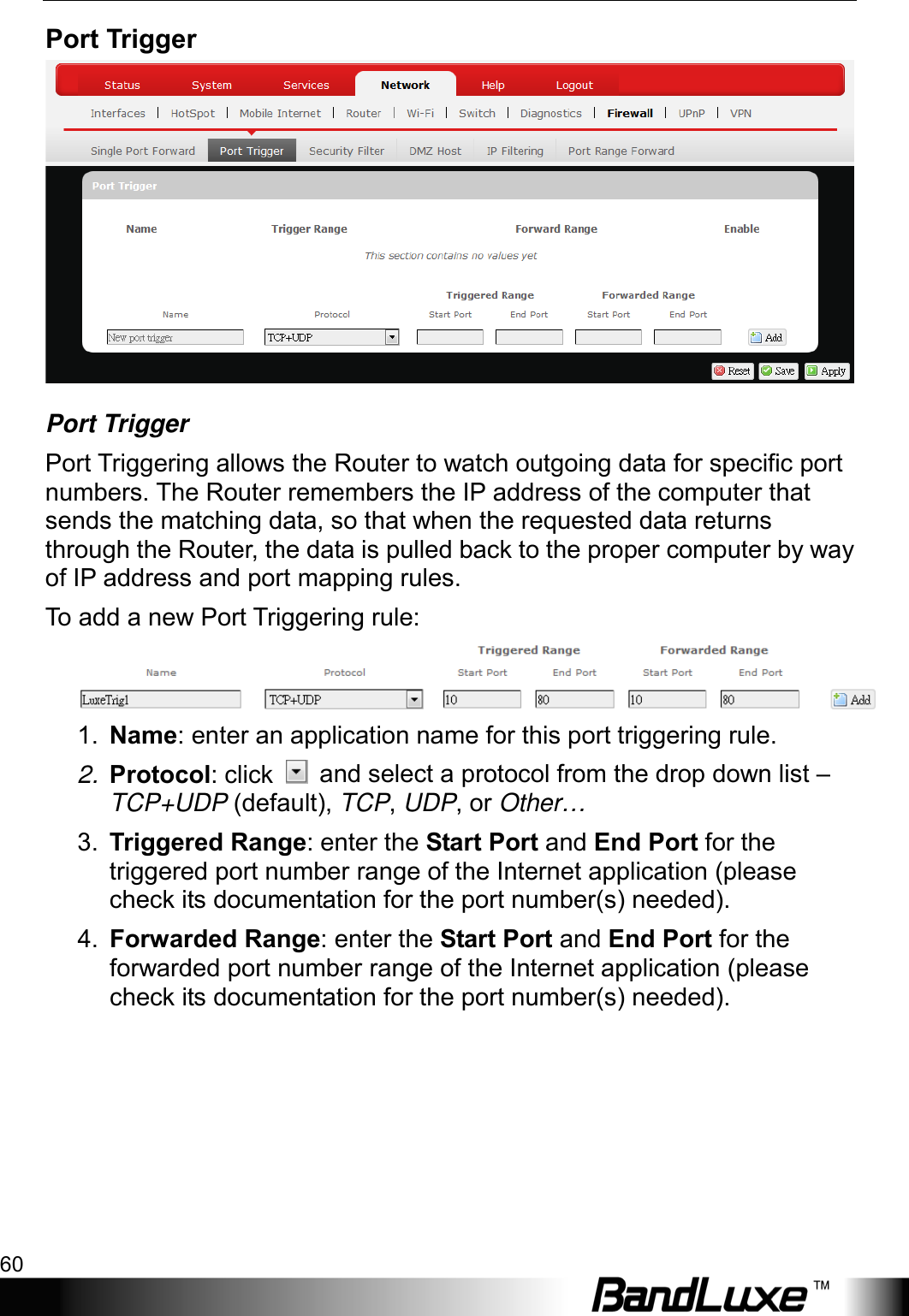
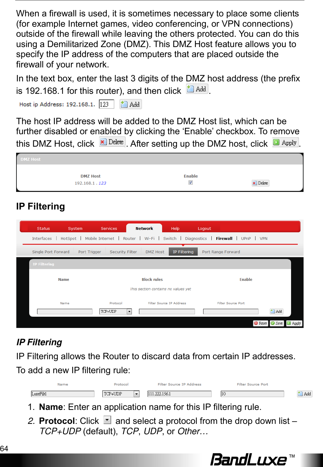
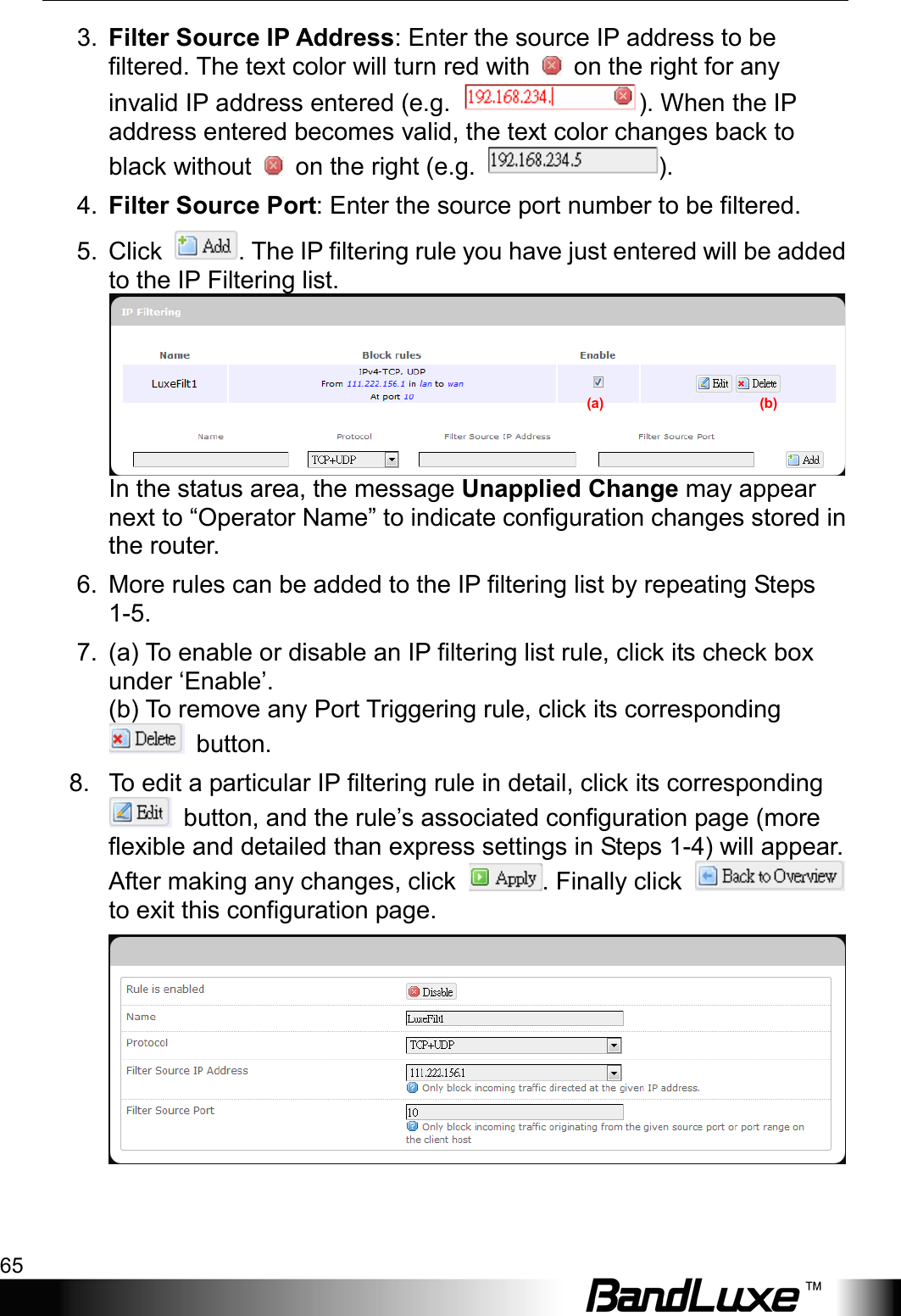
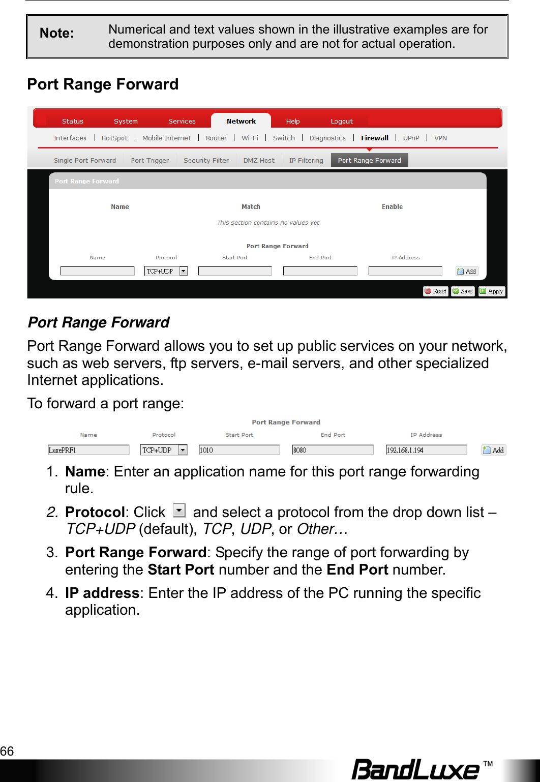
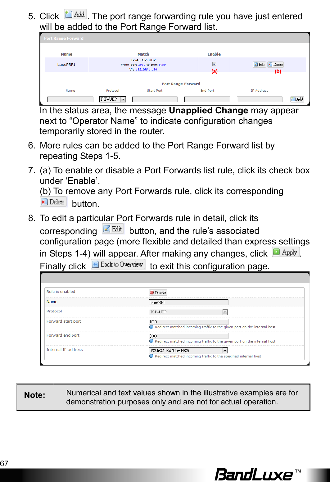
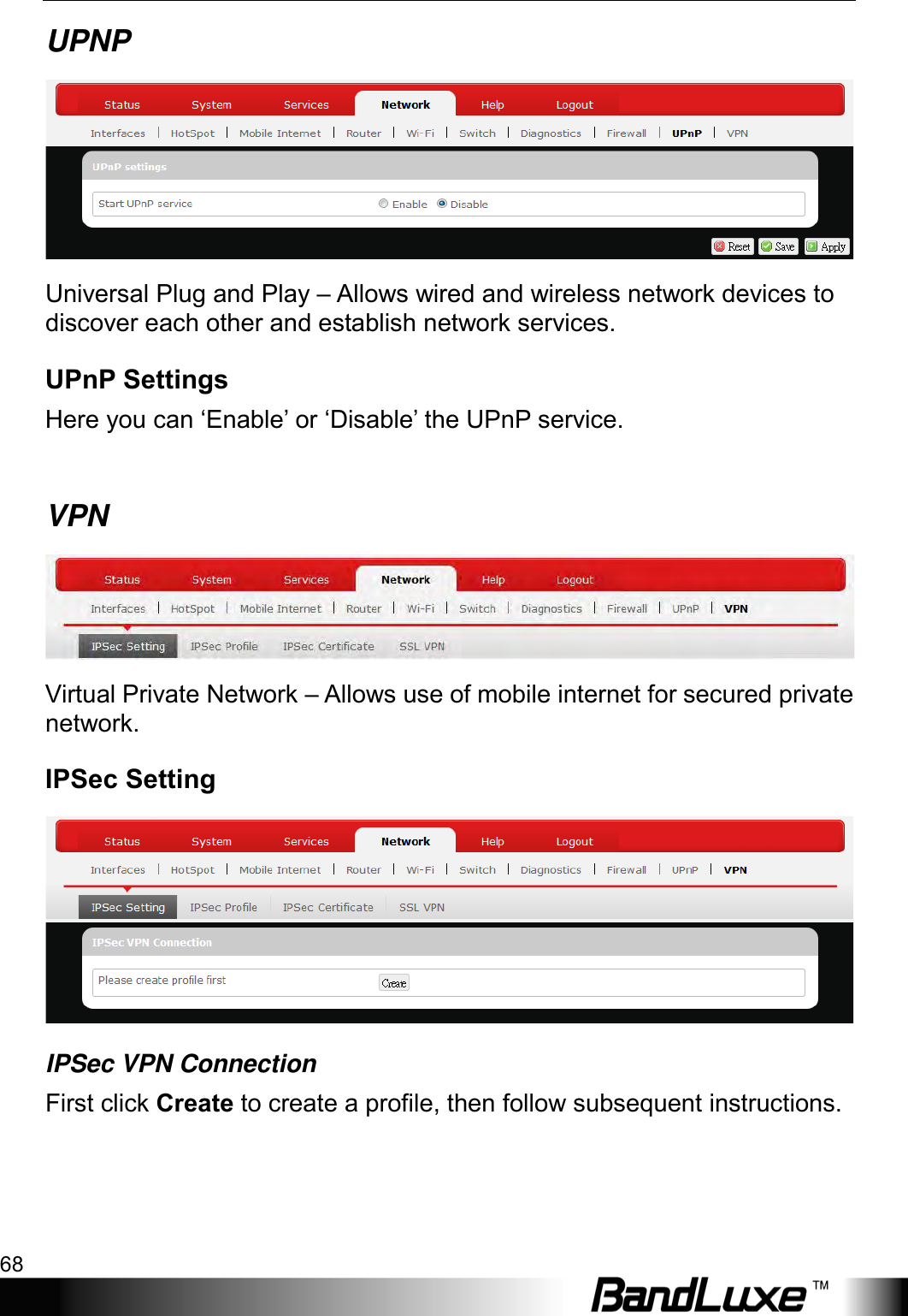
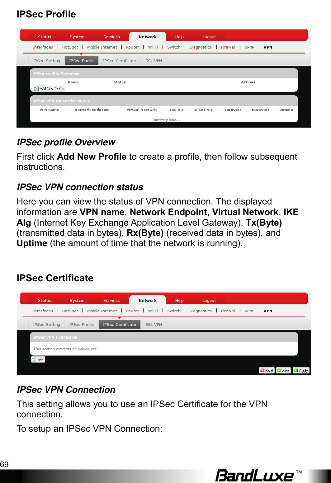
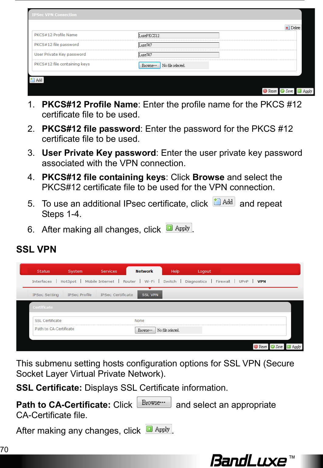
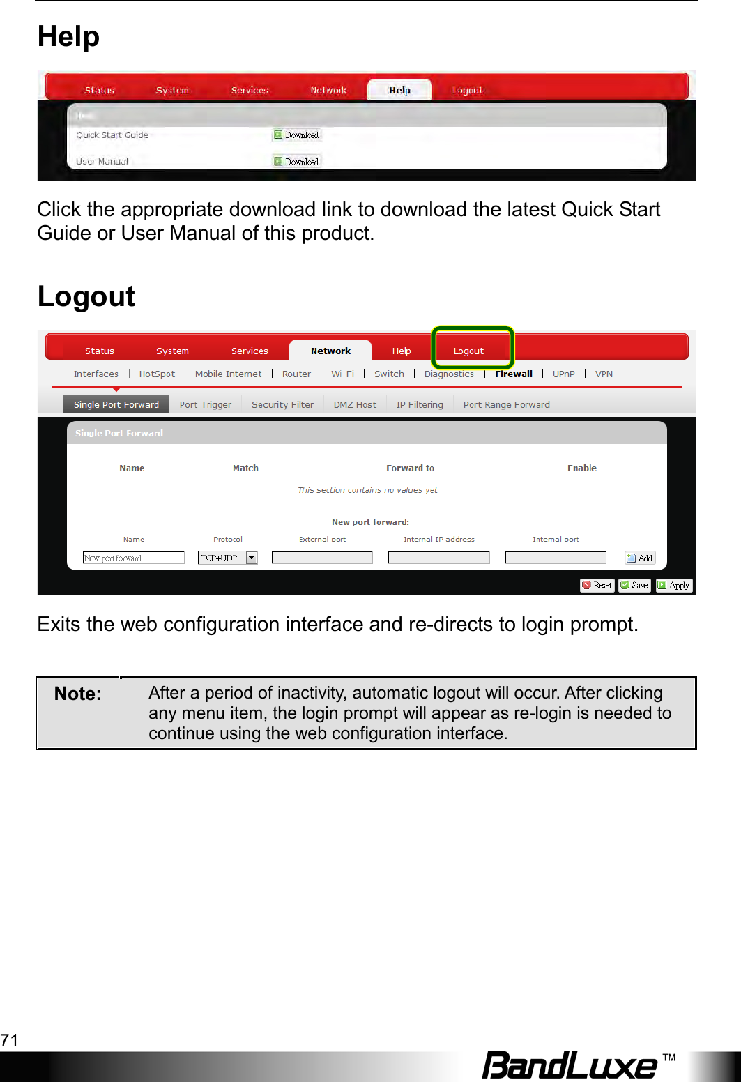
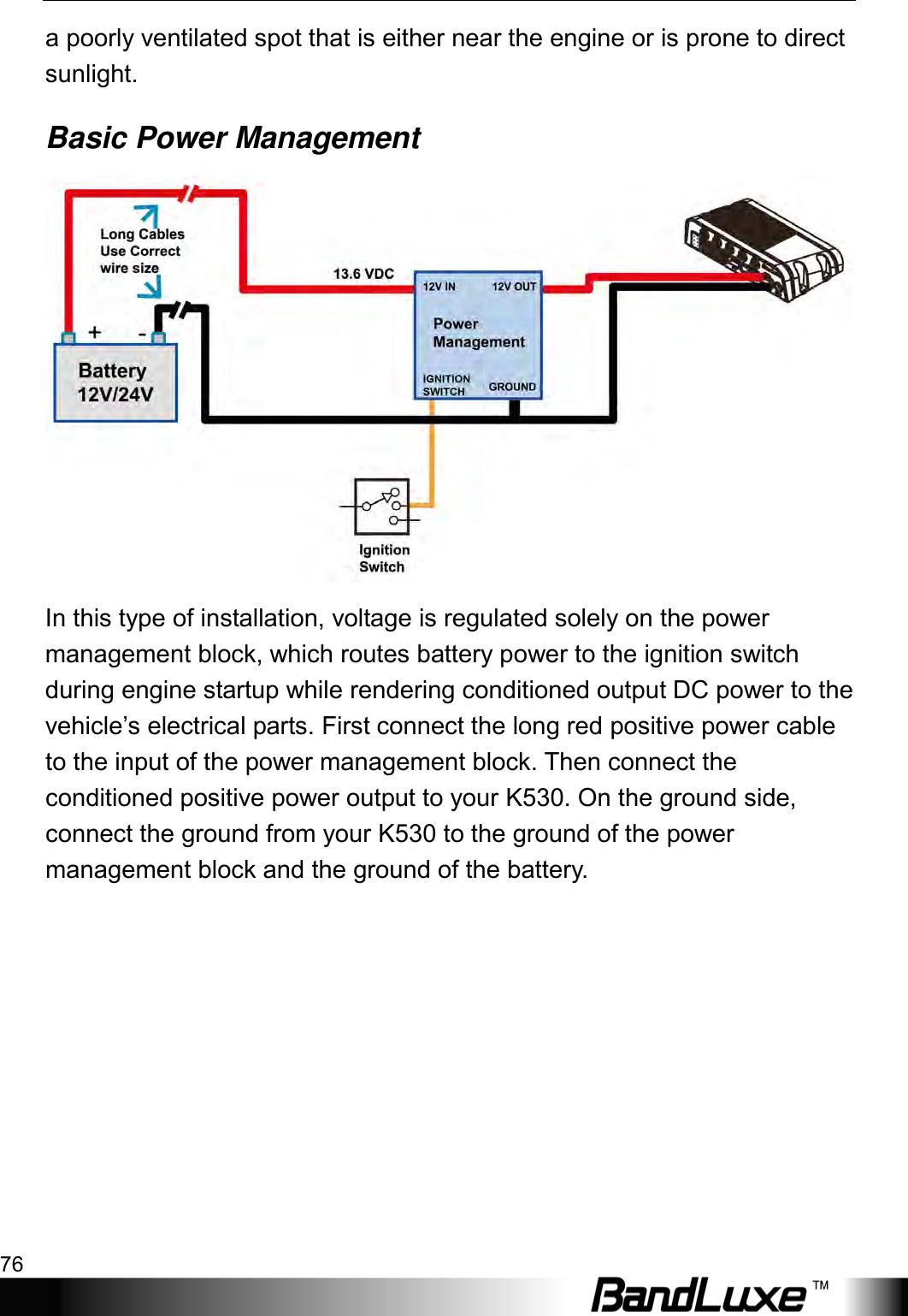
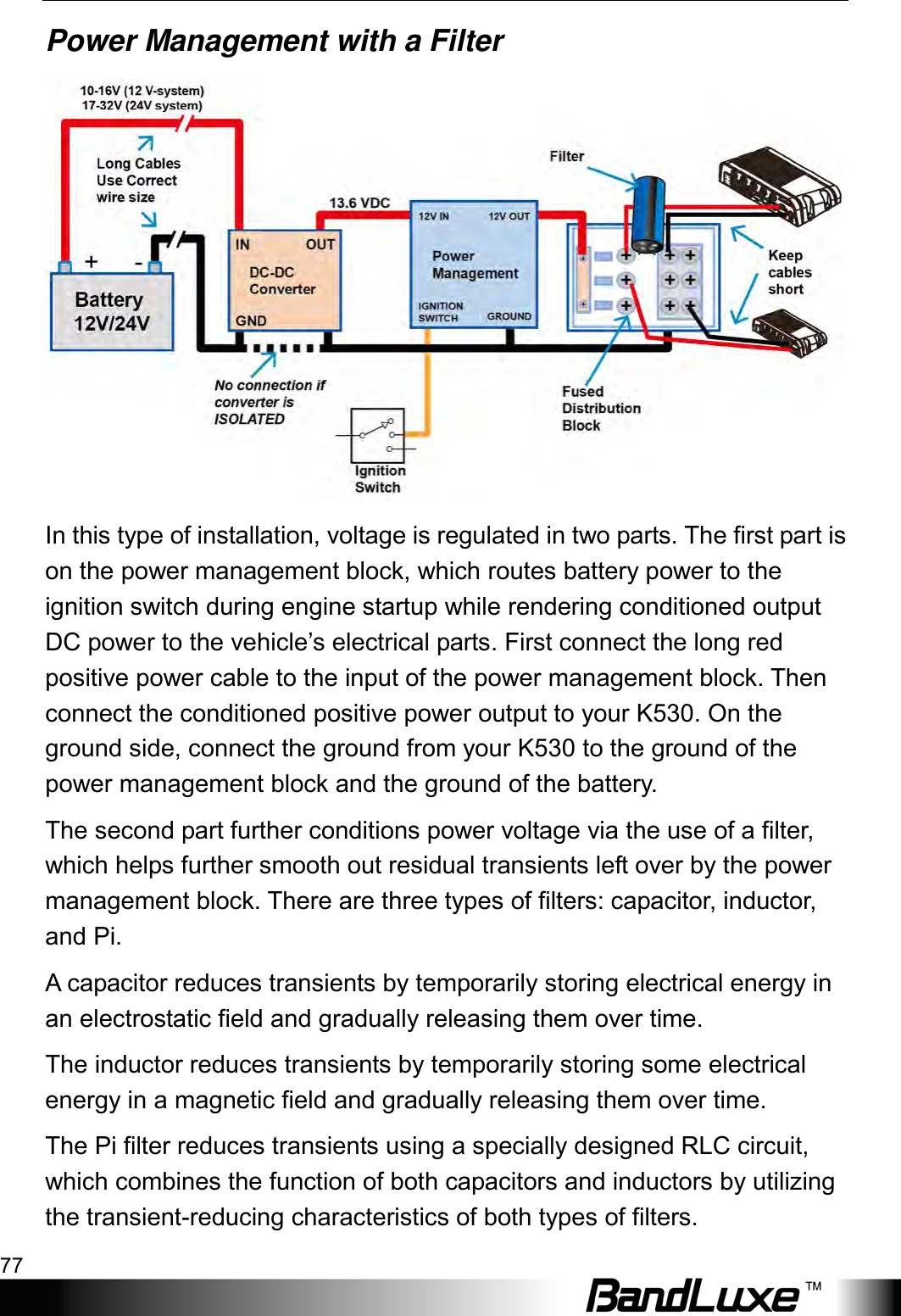
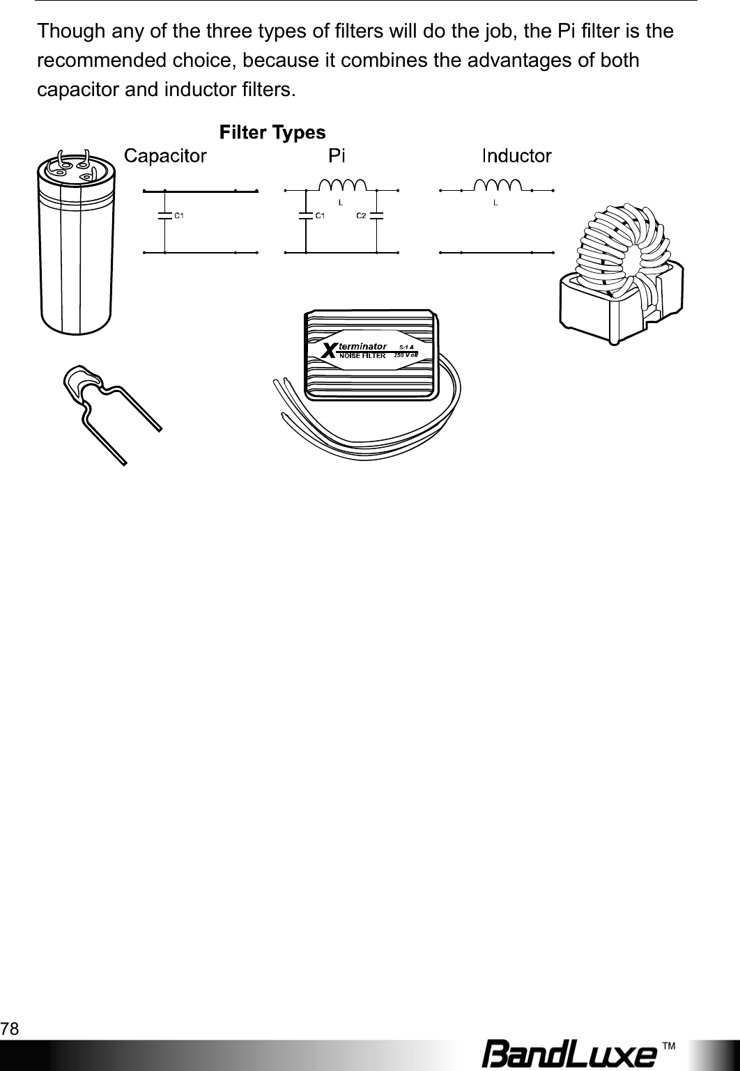
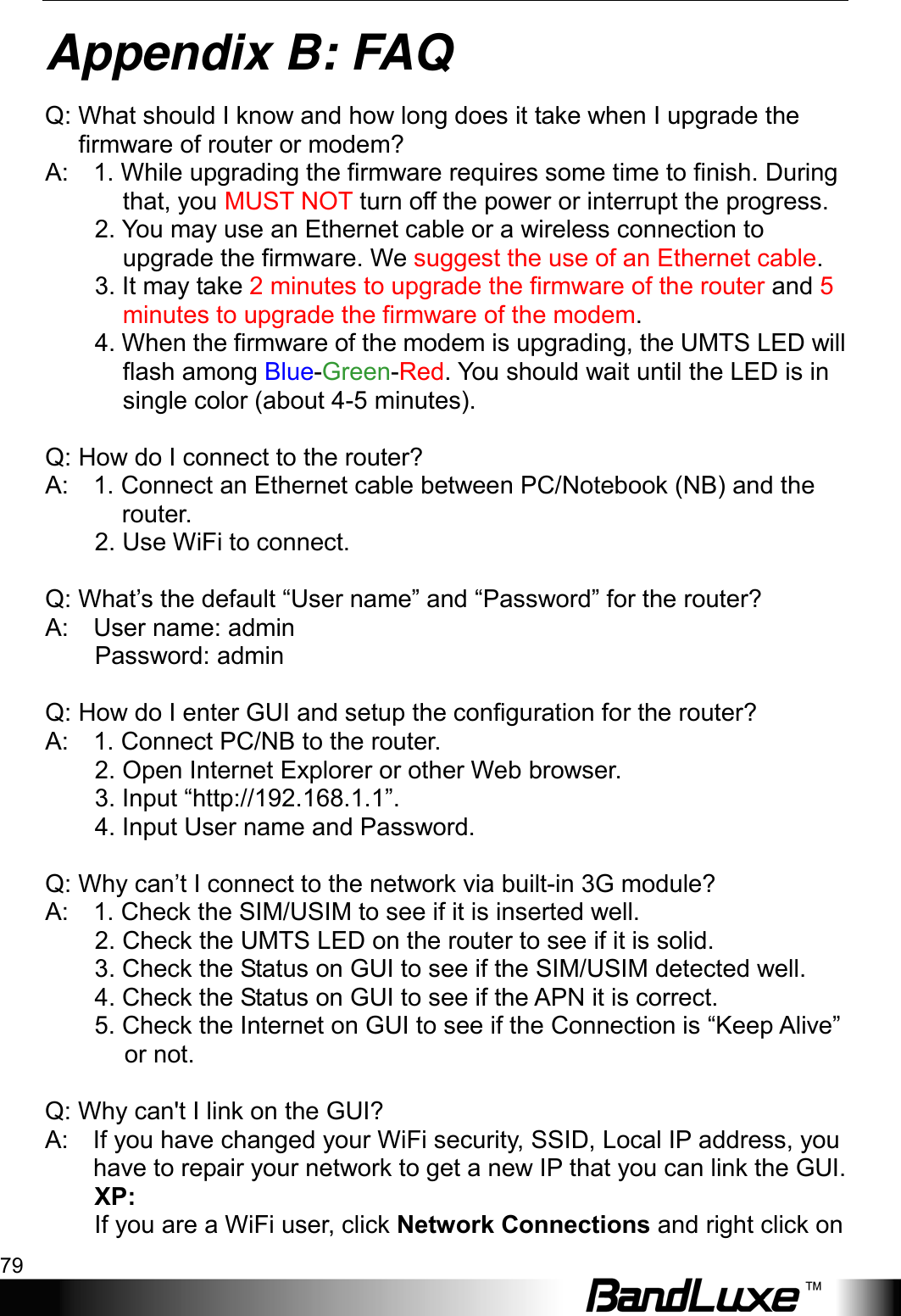
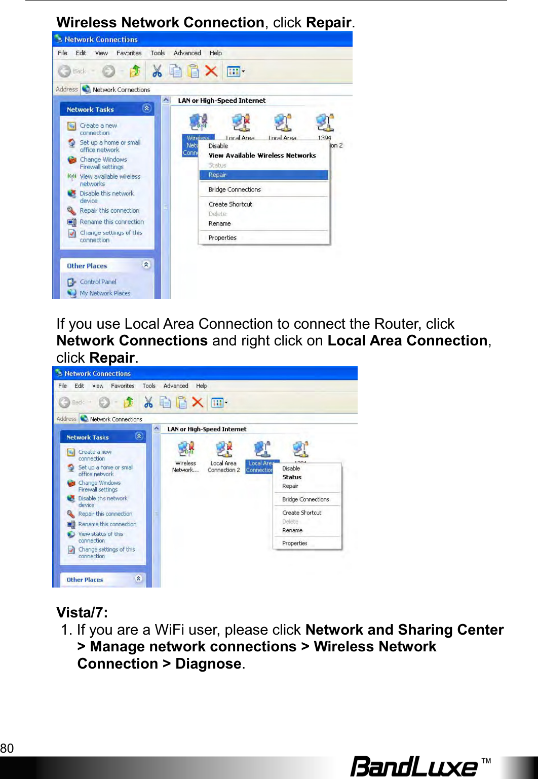
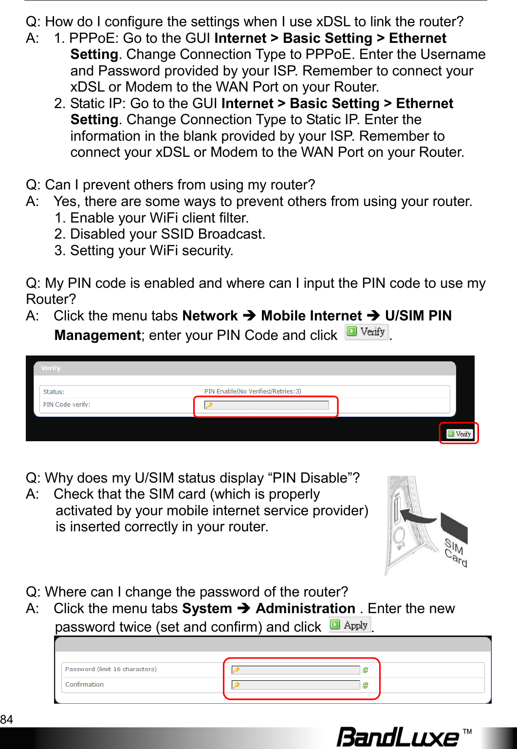
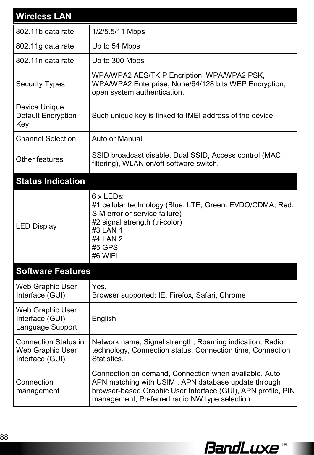
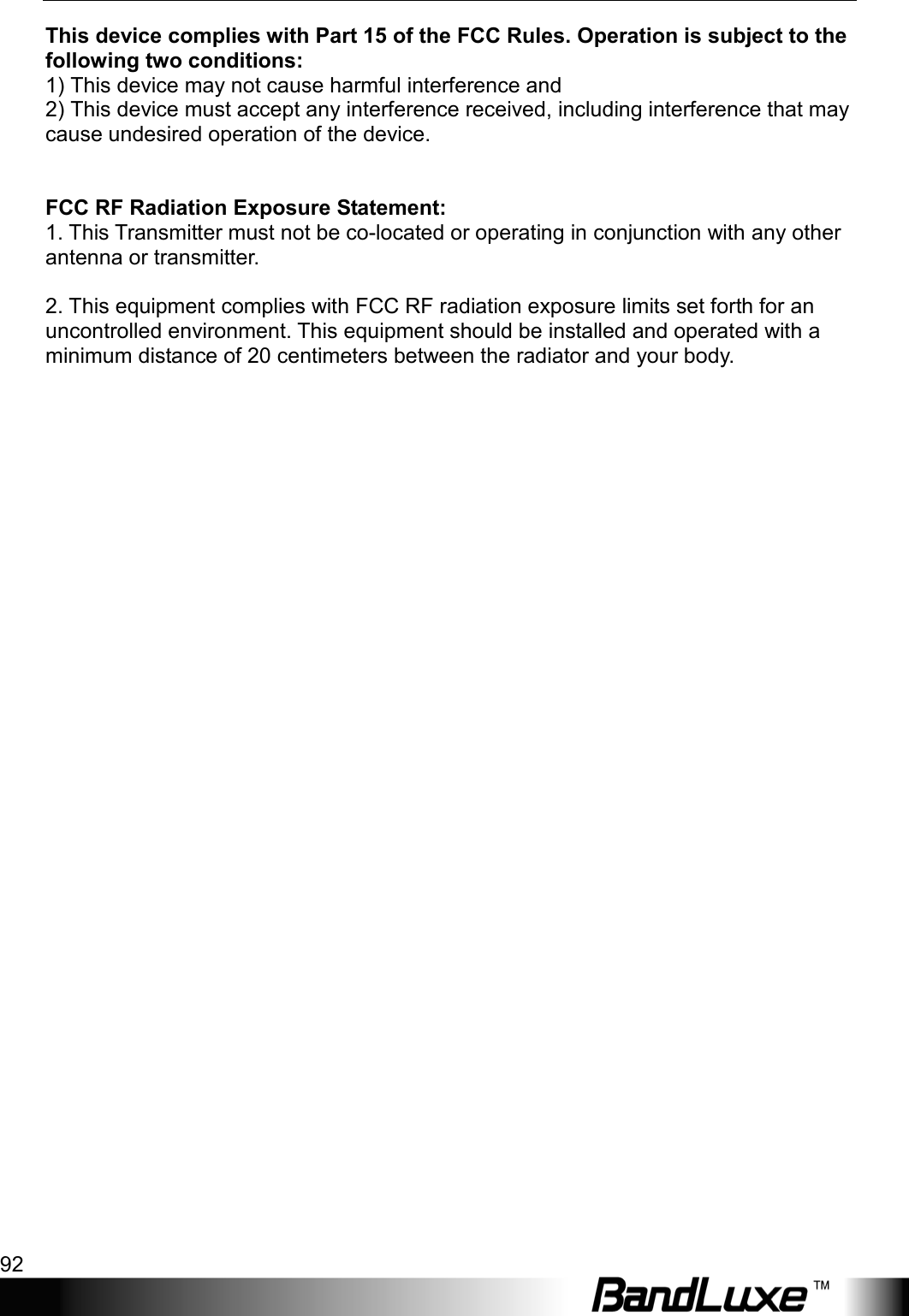
![Installation 11 Networks. Select default SSID [BR_LTE_xxxx] and enter default password (please refer to the router’s SSID/WPA sticker). The “xxxx” corresponds with the last 4 digits of MAC address. Click Connect. Wireless Connection (for Mac) Click the on the upper side of the screen to view available wireless networks. Select default SSID [BR_LTE_xxxx] and enter default password (please refer to the router’s SSID/WPA sticker). The “xxxx” corresponds with the last 4 digits of MAC address. Click Join. B. Wired Connection To connect your PC to the router via an Ethernet cable, connect one end of the cable to one of the four LAN ports on the router, and another end of the cable to an Ethernet port on your computer.](https://usermanual.wiki/BandRich/35K899/User-Guide-2243247-Page-13.png)