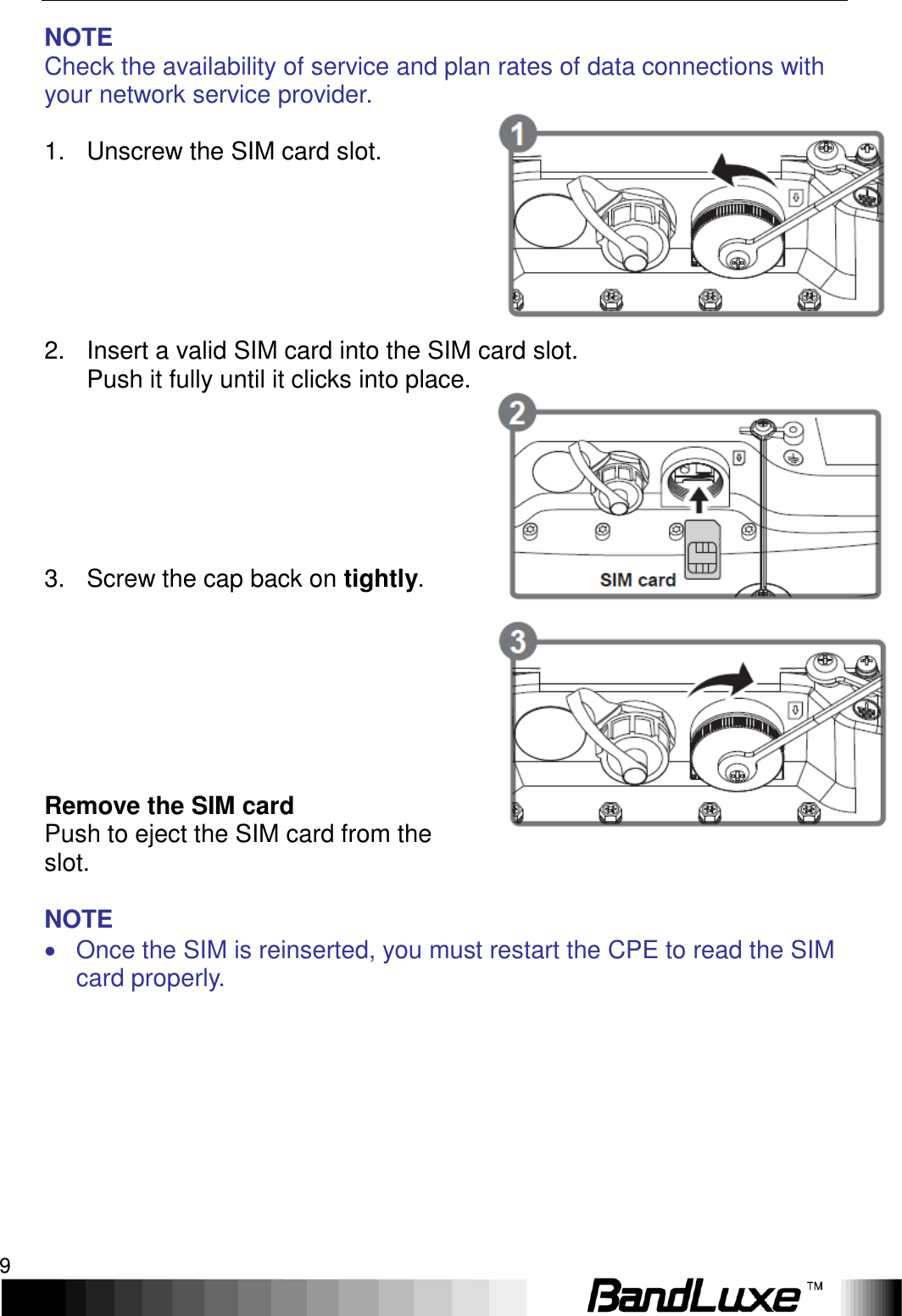
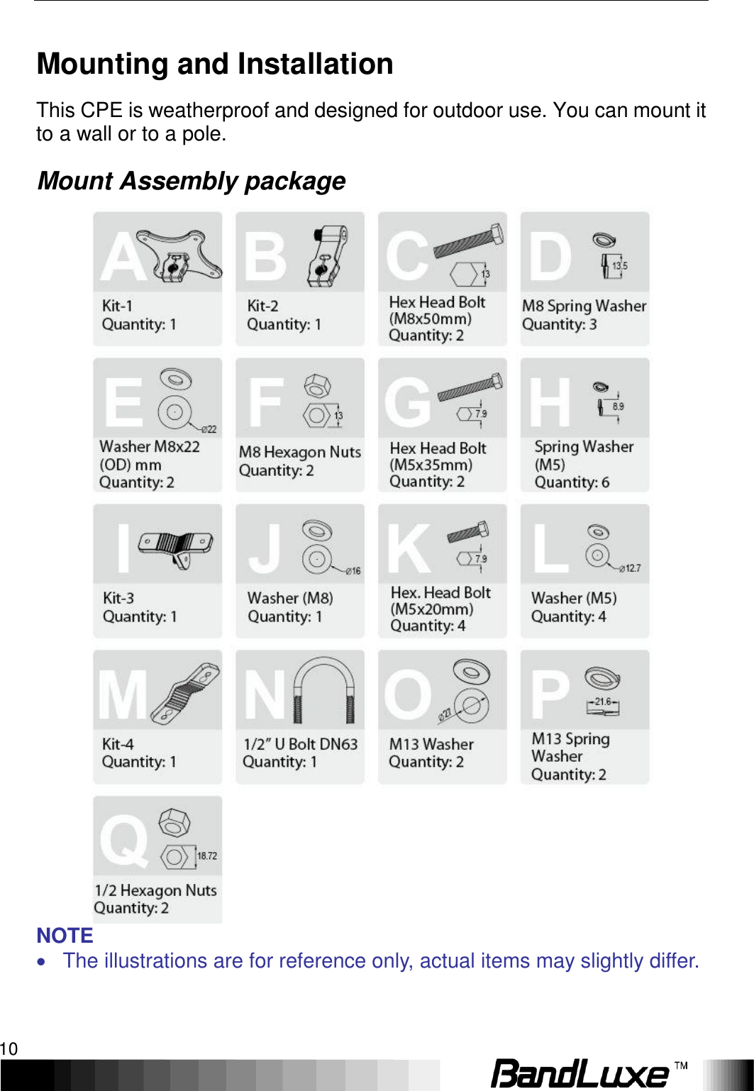
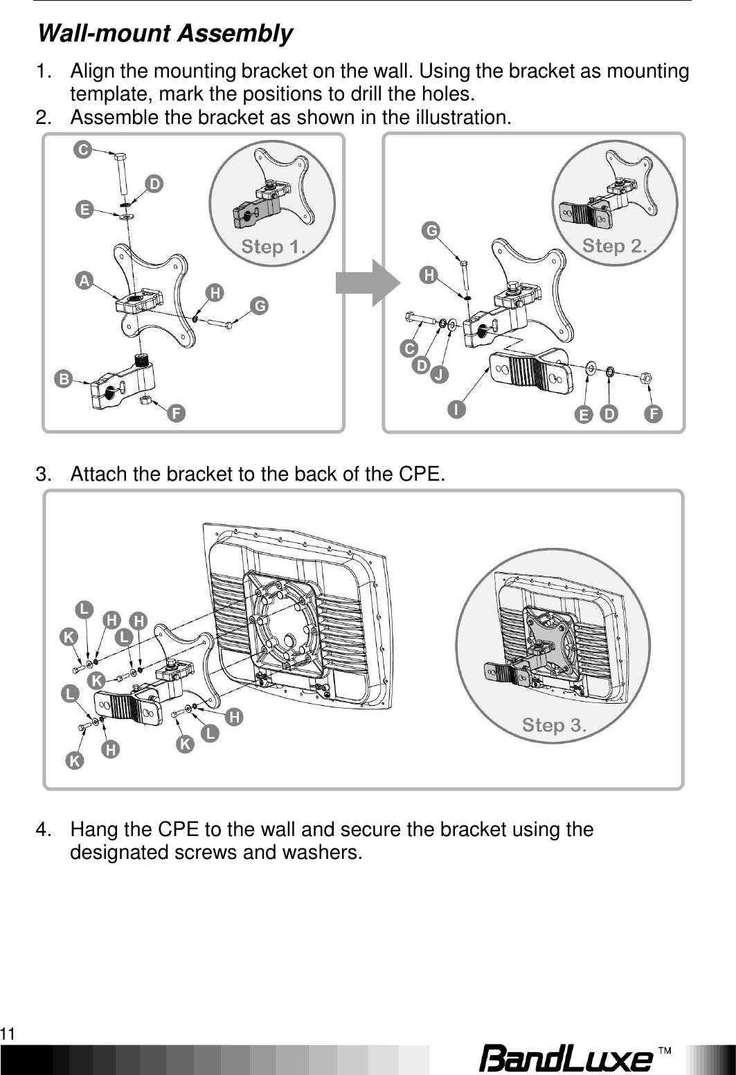
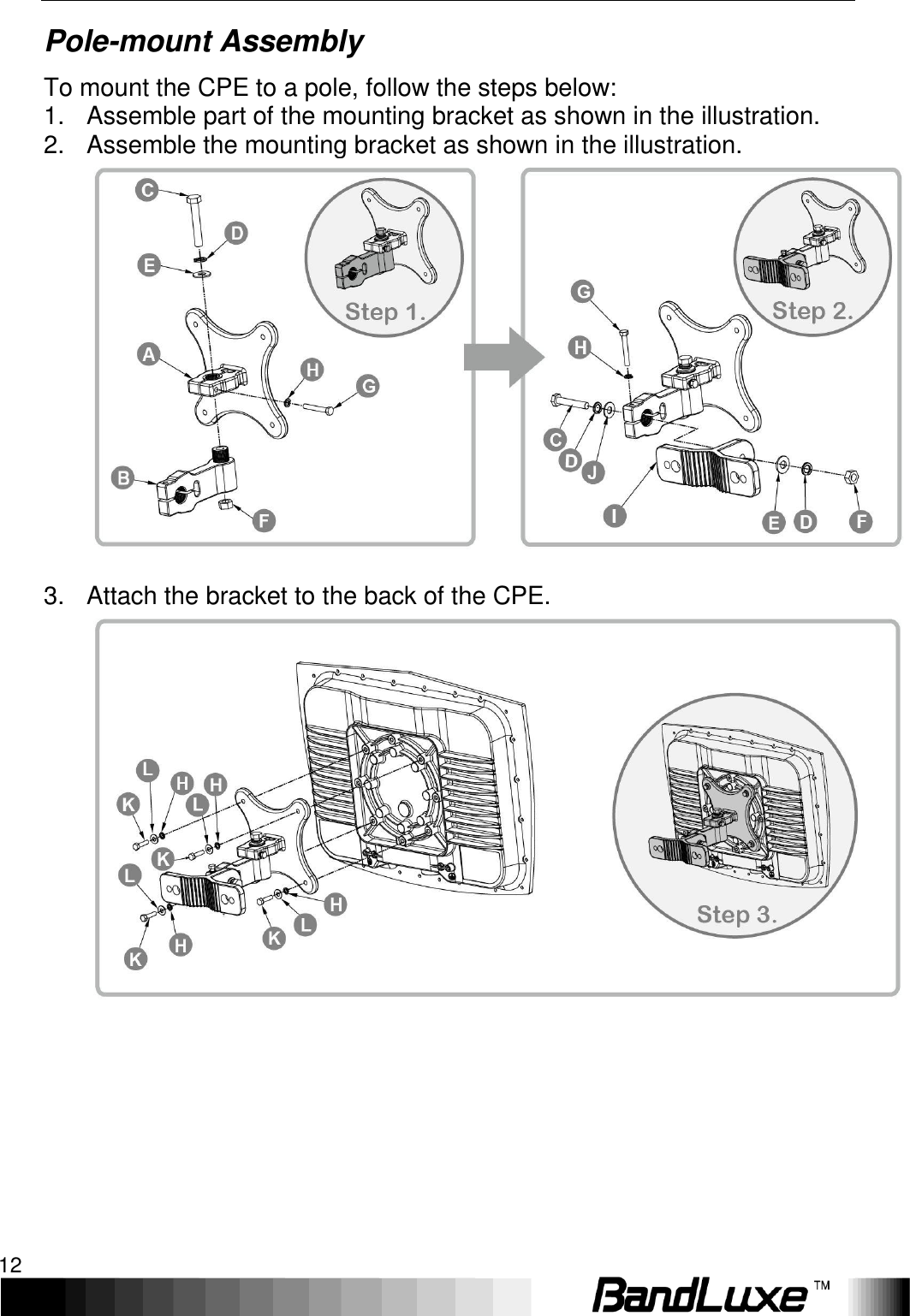
BandRich 580P LTE Outdoor CPE User Manual BandLuxe FieldPerfect

BandRich Inc. LTE Outdoor CPE BandLuxe FieldPerfect

User Manual.pdf

      User Manual       BandLuxe E580 Series   LTE Outdoor CPE        P/N:64003700011 Rev.D
   1 Table of Contents Product Overview ........................................................................... 4 Features .................................................................................................................. 4 Package Contents ................................................................................................... 4 Hardware Overview ................................................................................................. 5 Installation ...................................................................................... 6 Notice before installation ......................................................................................... 6 Important Installation Considerations ...................................................................... 7 Install the SIM card ................................................................................................. 8 Mounting and Installation ...................................................................................... 10 Mount Assembly package ..................................................................................... 10 Wall-mount Assembly ........................................................................................... 11 Pole-mount Assembly ........................................................................................... 12 Insert the Ethernet Cable ...................................................................................... 14 Assemble the Optional Water-Proof RJ-45 Jack ................................................... 15 Ground the CPE .................................................................................................... 16 Connect to Computers .......................................................................................... 16 Adjust the CPE position ........................................................................................ 17 Horizontal angle adjustment ................................................................................. 18 Vertical angle adjustment ..................................................................................... 18 Using Web-based Management ................................................... 19 Status .................................................................................................................... 20 Overview .............................................................................................................. 20 System ............................................................................................................................ 20 Network ........................................................................................................................... 21 DHCP Leases .................................................................................................................. 21 Local Network .................................................................................................................. 21 System Log .......................................................................................................... 21 VnStat Traffic Monitor ........................................................................................... 22 Graphs ............................................................................................................................. 22 Configuration ................................................................................................................... 22 Mobile Internet ..................................................................................................... 23 Signal Quality .................................................................................................................. 23 U/SIM Status ................................................................................................................... 23 Registered Network ......................................................................................................... 23 Internet Connection ......................................................................................................... 24 System .................................................................................................................. 25 System ................................................................................................................. 25 System Properties ........................................................................................................... 25 General Settings .......................................................................................................... 25 Language and Style ..................................................................................................... 26 Time Synchronization ...................................................................................................... 26 Remote System Log ........................................................................................................ 26 Administration ...................................................................................................... 27 Router Password ............................................................................................................. 27 Remote Access ............................................................................................................... 27 Signal LED ........................................................................................................... 28
 2  Signal Strength LED Indication Duration ......................................................................... 28 Backup / Flash Firmware ...................................................................................... 29 Backup / Restore ............................................................................................................. 29 Download backup ........................................................................................................ 29 Reset to defaults .......................................................................................................... 30 Restore backup ............................................................................................................ 30 Flash new firmware image............................................................................................... 30 Flash new module firmware image .................................................................................. 30 Flash new ipkg package .................................................................................................. 30 FOTA ............................................................................................................................... 31 Reboot.................................................................................................................. 31 Services ................................................................................................................ 32 Dynamic DNS ....................................................................................................... 32 Network ................................................................................................................ 33 Interfaces ............................................................................................................. 33 Interface Overview ........................................................................................................... 33 Common Configuration .................................................................................................... 34 General Setup .............................................................................................................. 34 Advanced Settings ....................................................................................................... 34 Physical Settings .......................................................................................................... 35 Firewall Settings ........................................................................................................... 35 Mobile Internet ...................................................................................................... 36 WWAN Setting ................................................................................................................. 37 Network Settings .......................................................................................................... 37 Auto APN Information .................................................................................................. 38 APN Profile Settings .................................................................................................... 38 Reset Modem ............................................................................................................... 38 U/SIM PIN Management .................................................................................................. 39 Scenario 1: No mobile internet service ........................................................................ 39 Scenario 2: Mobile internet service pending ................................................................ 39 Scenario 3: Mobile internet service enabled ................................................................ 40 SIM Management ............................................................................................................ 42 Scenario 1: SIM lock absent ........................................................................................ 42 Scenario 2: SIM lock present ....................................................................................... 42 Preferred Network ........................................................................................................... 43 Router .................................................................................................................. 43 Router Settings ................................................................................................................ 43 Router IP ...................................................................................................................... 43 DHCP Service .............................................................................................................. 44 Active DHCP Leases.................................................................................................... 45 Static Leases ................................................................................................................ 45 Advanced Routing settings .............................................................................................. 46 Static Routing ............................................................................................................... 46 Routing and Redirection Service ................................................................................. 47 VPN Passthrough......................................................................................................... 47 Firewall ................................................................................................................. 48 Single Port Forward ......................................................................................................... 48 Single Port Forward ..................................................................................................... 48 Port Trigger ...................................................................................................................... 50 Port Trigger .................................................................................................................. 50 Security Filter ................................................................................................................... 52 Firewall ......................................................................................................................... 53 Internet Filter ................................................................................................................ 53 Web Filters ................................................................................................................... 53 DMZ Host......................................................................................................................... 54
   3 IP Filtering ....................................................................................................................... 55 IP Filtering .................................................................................................................... 55 Port Range Forward ........................................................................................................ 57 Port Range Forward .................................................................................................... 57 Diagnostics ........................................................................................................... 59 Network Utilities ............................................................................................................... 59 Ping .............................................................................................................................. 59 Traceroute .................................................................................................................... 59 NS Lookup ................................................................................................................... 60 UPNP ................................................................................................................... 60 UPnP Settings ................................................................................................................. 60 Help ....................................................................................................................... 61 Logout ................................................................................................................... 61 Appendix A: FAQ .......................................................................... 62 Appendix B: Specifications ......................................................... 64 Appendix C: Important Safety Information and Glossary ......... 67 Europe – EU Declaration of Conformity ................................................................ 67 Federal Communication Commission Interference Statement .............................. 68 Glossary ................................................................................................................ 70
Product Overview 4  Product Overview Congratulations on your purchase of this LTE outdoor CPE. With this LTE (Long Term Evolution) CPE (which is also known as 4G CPE), you can share high speed mobile broadband connectivity in a wide range of computing environment. Before you begin using the LTE outdoor CPE, read this chapter to familiarize yourself with the device. Features   Embedded high gain directional antenna   IP66 protection against dust and water   Easy configuration based on Web Interface   Provide 10 – 30dB more coverage gain compared to indoor CPE   Support Passive Power over Ethernet.   Easy installation and use Package Contents The following items come with your package. If any of them is damaged or missing, please contact your retailer.                      LTE Outdoor CPE Mounting bracket Optional:   Plug head water resistant kits (RJ-45) Passive PoE adapter   (12V, E580A series) Passive PoE adapter   (48V, E580P series) Note: The pictures are for reference only, actual items may slightly differ.
  Product Overview 5 Hardware Overview      1 Power Power LED will remain lit while power is applied. 2 Signal strength Indicate receive signal strength. The Signal Strength LEDs are only used at the power on to assist the installation. The CPE will turn off all the Signal Strength LEDs after a timer expires from power on. Such design is to prevent the outdoor CPE becoming a potential target particularly at night. The default time is 60 minutes however, is user settable in the web GUI. 3 Mount base Attach the mount bracket. 4 Earth ground terminal Use a spring washer and an M4x8L screw to ground and protect CPE from lightning. See “Ground the CPE” on page 16 for more details. 5 Ethernet port Connect to a computer/ Passive PoE using an Ethernet cable. 6 Reset button  Short press to restart the device.  Long press for 5 seconds to reset the settings to the factory default settings. 7 SIM card slot Insert the SIM card. 8 USB port For use by technicians use only.
Installation 6  Installation Notice before installation Choose a solid and safe place (Wall or Pole) for CPE installation 1.  Choose the best location of the house and the orientation of the CPE to get the strongest signal reception from base station. 2.  The ambient temperature for E580A and E580P series must be within: E580A series: -10°C to 55°C E580P series: -40°C to 55°C         NOTE For lightning protection ground the CPE via Earth Ground Terminal and optimum reception, there are a few things you should consider before installation. Please see “Important Installation Considerations” on page 7 for more details. Prepare two Ethernet cables Be sure that one of the cables used is an outdoor grade CAT 5e (or above) Ethernet cable type and the length of the cables are adequate to reach the location of the CPE and indoor PPoE are. Prepare wrenches Prepare two adjustable wrenches or four combination wrenches. (size: 13mm x 2, 8mm x 1, and 19mm x 1) Warning: Do NOT start any traffic test (ex: throughput test and internet browsing) before the installer returns to the ground.
  Installation 7 Important Installation Considerations Before installing the outdoor CPE, consider the appropriate location, clearance, and device orientation. Location and Cable wiring 1.  Consult your Service Provider to find the best location and angle for getting the strongest signal from the base station. 2.  Do a walking test around the house to find the best spot with the strongest signal if you don’t obtain related information from Service Provider. 3.  Mount the CPE at the highest possible location with a clear view of the base station signal source. Buildings or other obstructions will affect the quality of the signal you receive. 4.  Keep the best distance as possible from other devices that may cause interference. 5.  Check if you can route the cable through the available ventilation holes to avoid unnecessary drilling and waterproofing the wall.  6.  Disconnect the power cord first before mounting the CPE. Otherwise this may result in personal injury due to electric shock.
Installation 8  Mounting 1.  Choose a solid wall/ground to mount the CPE. 2.  Mount on a wall/pole that can sustain the CPE dimensions and weight. 3.  Mount upright on a vertical surface.  Position Adjustment 1.  The CPE must be directed towards the nearest base station. By pointing the CPE in the proper direction ensures that you receive the strongest signal. 2.  Fine tune the signal by adjusting the orientation horizontally or vertically to increase the CPE signal strength. 3.  To verify the signal strength level:   Check the LEDs on the front panel - more lighted LEDs indicates stronger signal.   Access the web management and go to Basic Mode > Status > Mobile Internet > Signal Quality to view the Rx signal strength.  Warning:   To receive stronger signal and to avoid possible RF radiation, please do NOT place your head or body in front of the CPE while you are positioning the CPE or checking the signal strength LEDs on the front panel.                    Install the SIM card This CPE is specially designed for the 4G LTE network.
  Installation 9 NOTE Check the availability of service and plan rates of data connections with your network service provider.  1.  Unscrew the SIM card slot.       2.  Insert a valid SIM card into the SIM card slot.   Push it fully until it clicks into place.         3.  Screw the cap back on tightly.          Remove the SIM card Push to eject the SIM card from the slot.  NOTE   Once the SIM is reinserted, you must restart the CPE to read the SIM card properly.
Installation 10  Mounting and Installation This CPE is weatherproof and designed for outdoor use. You can mount it to a wall or to a pole. Mount Assembly package  NOTE   The illustrations are for reference only, actual items may slightly differ.
  Installation 11 Wall-mount Assembly 1.  Align the mounting bracket on the wall. Using the bracket as mounting template, mark the positions to drill the holes. 2.  Assemble the bracket as shown in the illustration.  3.  Attach the bracket to the back of the CPE.   4.  Hang the CPE to the wall and secure the bracket using the designated screws and washers.
Installation 12  Pole-mount Assembly To mount the CPE to a pole, follow the steps below: 1.  Assemble part of the mounting bracket as shown in the illustration. 2.  Assemble the mounting bracket as shown in the illustration.   3.  Attach the bracket to the back of the CPE.
  Installation 13   4.  Align a pole on the bracket and assemble the pole bracket as shown.     5.  Adjust the CPE position to an appropriate direction and secure the pole bracket using the designated screws and washers.
Installation 14  Insert the Ethernet Cable Unscrew the Ethernet port and insert one end of the Ethernet cable into the CPE port.   Note:   To have best protection against dust and water, Ethernet cable MUST be plugged with water-proof RJ-45 jack.
  Installation 15 Assemble the Optional Water-Proof RJ-45 Jack 1.  Unpack the RJ-45 water resistant kit. 2.  Assemble one end of the Ethernet cable as shown in the illustration.     NOTE   The Ethernet cable is not included in the package.
Installation 16  Ground the CPE For safety use, use the earth ground terminal to ground the CPE housing before making any connections.    You need the following:   Spring washer   M 4x8 L screw  NOTE   The spring washer and M4x8L screw are not included in your package.  To ground the CPE:    1.  Insert the washer to the M4x8L screw.   2.  Attach the screw halfway into the   earth ground terminal. 3.  Insert the grounding cable under   the washer. 4.  Tighten the screw.    Connect to Computers To use the Internet connection and configure the CPE settings, you must connect your CPE to a computer. Prepare two Ethernet cables for connection. 1. Insert the other end of the Ethernet cable to “P+D OUT” port of the PoE adapter. 2.  Connect another Ethernet cable to a Network Hub/Router or directly to PC/Laptop via PoE adapter (“Data/IN” port). 3.  Plug the PoE adapter to an electrical outlet.
  Installation 17   Adjust the CPE position To get a better reception, fine tune the CPE orientation (horizontally or vertically) to have the best signal strength shown from LED or other test equipment. Note:     LEDs (on the front panel) indicate signal strength.
Installation 18  Horizontal angle adjustment 1.  Loose the top knob using the wrench as shown. 2.  Swivel the device to the left or right to face the direction of the base station. 3.  Secure the knob using the wrench after the position is fixed.        Vertical angle adjustment 1.  Loose the side knob using the wrench as shown. 2.  Adjust the device position up or down to face the direction of the base station. 3.  Secure the knob using the wrench after the position is fixed.
  Using Web-based Management 19 Using Web-based Management This chapter will guide you on how to configure your CPE via the web-based utility.  Login  1. Launch a web browser. 2. On the address bar, enter http://192.168.1.1, then press Enter. 3. On the opening screen, enter the username (admin) and password (admin).   4. Click Login to login to the main screen.   5. Click one of the menu, submenu, and/or setting tabs to configure the system.  menu submenu setting
Using Web-based Management 20  Status This menu displays various statuses of the router. The associated submenu items are: Overview, System Log, VnStat Traffic Monitor, and Mobile Internet. Overview   The Overview submenu renders complete statistics for the router. System Displays system information: router model name, router firmware version, modem firmware version, phone number (MDN), ICCID, MIN (MSID), PRL version, IMEI, MEID, and local time.
  Using Web-based Management 21 Network Displays current network connection information of IPv4 WAN and/or IPv6 WAN: type of network assignment (e.g. DHCP), network address, netmask, gateway, DNS addresses 1 & 2, and time connected since the establishment of the current mobile internet connection. DHCP Leases Display DHCP lease information for each client: hostname, IPv4 address, MAC address, and lease time remaining. Local Network Displays local network information: local MAC address, router IP address, subnet mask, DHCP server, DHCP server change, start IP address, IP and address range System Log  The System Log submenu tracks system activities after power on.
Using Web-based Management 22   VnStat Traffic Monitor  The VnStat Traffic Monitor submenu displays graphic analysis of the router’s network traffic history. Graphs Displays VnStat network traffic history in various graphic analysis options: Summary display, Top 10 display, Hourly traffic, Daily traffic, and Monthly traffic. Click  , select an analysis option from the drop-down list, and click Update. The VnStat Graphs will be updated accordingly.     Configuration VnStat Traffic Monitor configurations can be made here. a) Monitor selected devices: Click the checkbox to enable/disable network monitoring of the displayed interface(s). b) Rest Traffic Flow: Click to discard previous network history log and start anew.
  Using Web-based Management 23 Mobile Internet  The Mobile Internet submenu displays mobile internet statistics. Signal Quality Displays signal strength of current mobile internet connection in dBm. U/SIM Status Displays current SIM card status: a) Read SIM Fail – No valid SIM card is inserted b) PIN Disable(Verified) – PIN protection is disabled while the SIM card status is verified; mobile internet service is available with this status. c) PIN Enable(No Verified/Retries:#) – PIN protection is enabled while the SIM card verification is pending (whereas # is the number of allowed PIN verifications remaining before SIM lock occurs). d) PIN Enable(Verified) – PIN protection is enabled while the SIM card status is verified; mobile internet service is available with this status. Registered Network a) Network Name – name of your mobile internet service provider
Using Web-based Management 24  b) Network Technology – mobile internet communication signal type. Examples are WCDMA (3G) and LTE (4G). c) Home/Roaming – displays current network roaming status: Home indicates mobile internet connection to the home location where the SIM card service is registered. Roaming indicates the extended mobile internet connection service in a location different from the home location where the SIM card service is registered. An example of roaming is when you travel abroad. Internet Connection Displays information of current internet connection: Connection Type, Internet IP Address, Gateway, and DNS 1/2.
  Using Web-based Management 25 System This menu is for system information and configurations.   System  System Properties Click either the “General Settings” or “Language and Style” tab to configure their respective settings. General Settings Local Time – displays current local time. To synchronize local time with the browser, click  . Hostname – enter the desired hostname in this check field.   Time Zone – sets the time zone associated with this router. Click on   and select the desired region.
Using Web-based Management 26  Language and Style  Language – sets the desired display language and style of the router. Click    and select the desired display language and style. Time Synchronization Enable NTP client:    click the checkbox to enable/disable. With this option enabled, two more options will appear– “Provide NTP server” and “NTP server candidates”. NTP server candidates 1/2:    enter the desired server candidates here. Remote System Log Server IP address:    displays IP address of the server. Server port:    displays port number of the server.
  Using Web-based Management 27 Administration  Router Password Login password of the router can be changed here. Enter new password in the ‘Password’ field, and enter the same password once again in the ‘Confirmation’ field. Remote Access This field specifies whether or not to allow remote access of this router.    After changing password and/or specifying remote access, click    . The screen will display a confirmation message after successful password change.
Using Web-based Management 28  Signal LED  Signal Strength LED Indication Duration Duration Setting:    specifies how long the signal strength LED will remain ON after establishing mobile internet connection. This setting is useful for power-saving and security purposes. The options are 5/10/30/60 minutes or Permanent Open.
  Using Web-based Management 29 Backup / Flash Firmware  Backup / Restore Download backup Here you can backup all current settings of the router to a TAR archive file on your computer or mobile device. Just click    . A dialog
Using Web-based Management 30  window will prompt you to open or save the archive file. Depending on the browser that you are using, the TAR file may be saved in the system download folder or a location of your choice. Reset to defaults Here you can restore the router to its original factory settings. Just click , and a dialog message will appear to indicate the factory reset process. After completion of the reset process, the router will automatically reboot and return to its initial login prompt. Restore backup Here you can restore router settings previously saved as a TAR archive file on your computer or mobile device. Just click    to find and select the previously saved TAR archive file, and then click ‘Open’. Confirm that the TAR filename appears beside the    button   and click  . The system will reboot after completion of backup restoration.   Flash new firmware image This option allows you to upgrade this router with the updated firmware image. Just click    to find and select the firmware image file, and then click ‘Open’. Confirm that the firmware filename appears beside the   button and click  . The system will reboot after successful upgrade.   Flash new module firmware image This option allows you to upgrade this router with the updated module firmware image. Just click    to find and select the firmware package file, and then click ‘Open’. Confirm that the firmware filename appears beside the    button and click  . The system will reboot after successful upgrade. Flash new ipkg package This option allows you to upgrade this router with the updated IPKG package. Just click    to find and select the IPKG package file, and then click ‘Open’. Confirm that the IPKG package filename appears beside the    button and click  . The system will reboot after successful upgrade.
  Using Web-based Management 31 FOTA This option (Firmware Over The Air) allows you to automatically or manually upgrade this router’s firmware wirelessly.   For automatic wireless update, enable “Auto check” and enter the desired time interval (in hours) between each check of the BandRich website for firmware update. For manual wireless update, disable “Auto check”. Confirm that the “Check link for Router” and “Check link for Module”  fields have appropriate web address(es) present in their text boxes, i.e. http://www.bandrich.com/mdm9x15/ . Click    to activate the wireless update configurations into effect. To immediately check for firmware upgrade, click Check.  Warning: Upgrading firmware may take a few minutes; do not turn off the power or press the Reset button during upgrade.  Reboot  Click ‘Perform reboot’ to restart the router.
Using Web-based Management 32  Services Dynamic DNS  The Services menu hosts configuration options for DDNS (Dynamic Domain Name Service), which is a system that allows the domain name data held in a name server to be updated in real time. It allows an Internet domain name to be assigned to a computer with a varying (dynamic) IP address. Before you can use this feature, you need to sign up for DDNS with a DDNS provider, www.dyndns.org or www.TZO.com. Enable: Check or un-check this box to enable or disable DDNS. Service: Specifies the DDNS service URL. From the drop-down list, click   and select an URL from the list. Hostname: Enter the hostname for your DDNS account. Username: Enter the username for your DDNS account. Password: Enter the password for your DDNS account.
  Using Web-based Management 33 Network Interfaces  The Interfaces submenu allows interface configurations of different networks connected to this router. The configuration items are the same for each network with different default settings. Interface Overview Here you can see the brief network status summary for LAN (local area network) and WAN (wide area network). To configure LAN or WAN interfaces, click the appropriate Edit button and follow the below section Common Configuration for more details.
Using Web-based Management 34  Common Configuration General Setup  Status: Displays protocol-dependent statistics of network connection. Protocol: Specifies the protocol to be used for the network. The available protocols are Static address, DHCP client, Unmanaged, PPP, PPtP, PPPoE, PPPoATM, UTMS/GPRS/EV-DO, and L2TP. (Protocol-dependent configuration items): Different protocol-dependent configuration items will appear according to the protocol chosen. Advanced Settings  This tab is for advanced users to make detailed configurations of protocol-related settings. Actual configuration items will vary according to the protocol chosen in the tab item General Setup.
  Using Web-based Management 35 Physical Settings  This tab is for selection of physical interface of the associated network. Click one of the available physical interfaces or click   and enter your own interface name. This tab is not available for the following protocols: PPP, PPtP, PPPoE, PPPoATM, UTMS/GPRS/EV-DO, and L2TP. Firewall Settings  This tab is for adjustment of firewall settings. Click the desired network as the desired firewall zone assigned to this interface. Furthermore, you can remove the interface from the associated zone by entering “unspecified” in the unspecified -or- create field and clicking  , or you can define a new zone by entering your own firewall name in the unspecified -or- create field and clicking  .
Using Web-based Management 36  Mobile Internet   The Mobile Internet submenu is for setup and adjustment of mobile internet connection and furthermore has four setting tabs: WWAN Setting, U/SIM PIN Management, SIM Management, and Preferred Network.
  Using Web-based Management 37 WWAN Setting  Network Settings Roaming Connection: Enables or disables current roaming setting. Update Profile: Click Update to update the network profile. Update PRL: Click Update to update the preferred roaming list. APN Update: Displays the current APN (Access Point Name) version. To get the latest version of APN, click .
Using Web-based Management 38  APN: ‘Auto’ – Uses automatic APN profile settings for network; this is the default APN setting ‘Manual’ – Allows the manual choice of APN Profile Settings for network. Profile Selection: This item appears when APN is set to ‘Manual’. Auto APN Information This section displays automatic Access Point Name information. APN Profile Settings For Advanced Users   This section allows you to establish your own Access Point Name profile settings. To establish a new APN profile, type in a new APN profile name in the text box and click  .  Enter the APN, username, and password. Click  . Reset Modem Click Perform reset to reset this router to its factory default settings.
  Using Web-based Management 39 U/SIM PIN Management  This submenu features configurable items are dependent on the router’s mobile internet status, as detailed below. Scenario 1: No mobile internet service Without a valid SIM card inserted into the router, the Verify dialog will show the following SIM card status:  Here the Verify dialog shows SIM status as “Read SIM Fail”, meaning that no valid SIM card is inserted. Scenario 2: Mobile internet service pending If a valid SIM card is inserted into the router requiring PIN code verification, the Verify dialog will show the following SIM card status:  Here the Verify dialog shows the SIM status as “No Verified/Retries:3”, meaning that a valid SIM card is inserted with PIN code verification pending. Enter your SIM card verification code in the text box of “PIN Code verify:”, and then click  . Once the PIN code verification is finished, the router is ready to use the SIM card’s associated mobile
Using Web-based Management 40  internet access, and the top right status area will be updated accordingly.                         Operator Name: Displays the name of the internet service provider WiFi SSID 1 Counter: Shows number of clients currently connected to WiFi SSID 1 network WiFi SSID 2 Counter: Shows number of clients currently connected to WiFi SSID 2 network Roaming Status: Displays current roaming status (Carrier) Signal: Displays strength of the indicated signal type (Carrier) For example:   1. Without mobile internet connection, the display will be      (no carrier, no signal). 2. If WCDMA (3G) mobile internet connection is established, the display will be    (WCDMA carrier, excellent 4-bar signal strength). Scenario 3: Mobile internet service enabled If a valid SIM card is inserted into the router with PIN code verified, the configuration dialog will be ‘Setting’ and/or “Change PIN” to allow further SIM card management (click    after making changes):  Setting SIM Status: Shows current SIM card status.   “PIN Enable” means that the SIM card is enabled for
  Using Web-based Management 41 mobile internet access.   “PIN Disable(Verified/Retries:#)” means that the SIM card is enabled for mobile internet access without requiring PIN code verification. Note that if PIN protection is re-enabled, # is the number of allowed PIN verifications remaining before SIM lock occurs. PIN Protection: Enables or disables the PIN protection by clicking   and making the appropriate choice from the drop-down list. PIN Code If PIN protection is enabled, you need to enter PIN code in this text box for making changes in this ‘Setting’ dialog.  Change PIN This option is configurable only if PIN Protection is enabled. Here you can change the PIN code for enhanced SIM card security. Old PIN Code: Enter the old PIN code. New PIN code: Enter the new PIN code. New PIN code confirm: Enter the same new PIN code again for PIN code confirmation.  Click    after making changes in ‘Setting’ and/or “Change PIN”.
Using Web-based Management 42  SIM Management  Here you can see the current SIM lock status.   Scenario 1: SIM lock absent  “SIM no lock” means that the SIM card is unlocked.  Scenario 2: SIM lock present If your SIM card is locked for some reason, here you can also enter the SIM unlock code to unlock it. After entering the SIM unlock code in the text box “SIM Unlock”, click  .
  Using Web-based Management 43 Preferred Network  Here you can select the preferred mobile network type by clicking   and making a choice from the drop-down list. The default choice is Auto. Other available choice examples are LTE (4G) and WCDMA (3G). Router Router Settings  Router IP  Local IP Address: The default local IP address of this router is 192.168.1.1. If this address conflicts with another local network device, you can enter another local IP
Using Web-based Management 44  address here. Subnet Mask: Displays current Subnet Mask Device Name: The current device name is displayed in gray color. The device name can be changed by typing in the new device name in this text box. MTU: The current MTU (maximum transmission unit with default value of 1500 bytes) is displayed in gray color. The MTU can be changed by typing in the new MTU value in this text box. DHCP Service  DHCP Server: Enables or disables the DHCP Server feature. Start IP Address: Specifies the starting number of the last 3 digits of assigned client IP address. For example, the default value of 100 means that the first assigned client IP address will be 192.168.1.100; the next assigned client IP address will be 192.168.1.101; and so on… Maximum Number of Users: Specifies maximum number of users for this router. The default setting is 150 users. Client Lease Time: Specifies the amount of lease time allocated to clients of this router, i.e. the expiry time of leased addresses. Use ‘h’ to indicate hours or use ‘m’ to indicate minutes.
  Using Web-based Management 45 IP Address Range: Displays assignable local IP address range of this router Primary DNS: If needed, specify the primary Domain Name System here. Secondary DNS: If needed, specify the secondary Domain Name System here. Active DHCP Leases  This section displays active DHCP lease information for each client: Hostname, IPv4 address, MAC address, and Lease time remaining. Static Leases  This option allows fixed IP address and symbolic hostname assignments for DHCP clients. To add a static lease, first click  .  Enter the desired hostname. Choose the desired MAC address and IPv4-Address (click    and select an rule from the drop-down list; if “--Custom--" is selected, the drop-down list will change to a text box to allow you to enter your custom address). The MAC address is for host identification, whereas the IPv4 address
Using Web-based Management 46  specifies the fixed address for static lease. To remove any unwanted static lease, just click the corresponding   button. Click    after making any changes.  Advanced Routing settings  Static Routing This option allows fixed network routing path assignment (as opposed to the initial adaptive routing). To add a static network routing path, click  . To remove any unwanted static network routing path, click the corresponding   button. Click    after making any changes.
  Using Web-based Management 47  Interface: Click    and choose ‘lan’ (local area network) or ‘wan’ (wide area network). Target: Enter the target host IP or network address here. IPv4-Netmask: Displays the IPv4-Netmask address (the default is 255.255.255.255). A custom IPv4-Netmask can also be specified here. IPv4-Gateway: If needed, a custom IPv4-Gateway address can be specified here. Metric: Specifies the network path priority number (usually associated with the network path’s administrative distance). The lower the metric number, the higher priority of this static route in the network routing protocol. The default value is 0 (highest priority). A different metric number can also be specified here.  Note: If contents in the text box is invalid, a    will appear on the right side of the text box, and the text color changes to red. For example, the following demonstrates an invalid target Host-IP or Network address:    Routing and Redirection Service This option enables or disables Network Address Translation (NAT) service, which is a standard that allows multiple computers on a private network to share a single IP address. VPN Passthrough A Virtual Private Network (VPN) is a type of secured private network connection, built upon publicly-accessible infrastructure such as the
Using Web-based Management 48  Internet. They usually provide connectivity to various devices behind a gateway or firewall.  IPSec Passthrough: IP Security (IPSec) provides authentication and encryption. Since it is mainly a Layer 3 technology, it can secure all data on the network. To allow IPSec tunnels to pass through the Router, click ‘Enabled’. PPTP Passthrough: Point-to-Point Tunneling Protocol (PPTP) allows you to establish a connection to an enterprise network. To allow PPTP tunnels to pass through the Router, click Enabled. L2TP Passthrough:  Layer 2 Tunneling Protocol (L2TP) is an extension of the Point-to-Point Tunneling Protocol and is also used to establish virtual private networks. To allow L2TP tunnels to pass through the Router, click Enabled. Firewall Single Port Forward  Single Port Forward Port Forwarding allows you to set up public services on your network, such as web servers, ftp servers, e-mail servers, and other specialized Internet applications. To forward a single port:
  Using Web-based Management 49  1. Name: enter an application name for this port forwarding rule. 2. Protocol: click    and select a protocol from the drop down list – TCP+UDP (default), TCP, UDP, or Other… 3. External port: enter the port number of the external port used by the server or Internet application. Afterward, this port number will be echoed to the text box of “Internal port”. 4. Internal IP address: click    and select an IP address from drop-down list, or select “--custom--" and enter IP address in text box. 5. Internal port: this text box will automatically receive port number entered in the text box of “External port”, or you can enter your own port number in the same text box. 6.  Click  . The port forwarding rule you have just entered will be added to the Port Forwards list.  In the status area, A    may appear next to “Operator Name” to indicate configuration changes temporarily stored in the router. 7.  More rules can be added to the Port Forwards list by repeating Steps 1-6. 8.  (a)To enable or disable a Port Forwards list rule, click its check box under ‘Enable’. (b) To remove any Port Forwards rule, click its corresponding   button. 9.  To edit a particular Port Forwards rule in detail, click its corresponding    button, and the rule’s associated configuration page (much more flexible and detailed than express settings in Steps 1-6) will appear. After making any changes, click . Finally click    to exit this configuration page.(a)                              (b)
Using Web-based Management 50    Note: Numerical and text values shown in the illustrative examples are for demonstration purposes only and are not for actual operation.  Port Trigger  Port Trigger Port Triggering allows the Router to watch outgoing data for specific port numbers. The Router remembers the IP address of the computer that sends the matching data, so that when the requested data returns through the Router, the data is pulled back to the proper computer by way of IP address and port mapping rules. To add a new Port Triggering rule:
  Using Web-based Management 51  1. Name: enter an application name for this port triggering rule. 2. Protocol: click    and select a protocol from the drop down list – TCP+UDP (default), TCP, UDP, or Other… 3. Triggered Range: enter the Start Port and End Port for the triggered port number range of the Internet application (please check its documentation for the port number(s) needed). 4. Forwarded Range: enter the Start Port and End Port for the forwarded port number range of the Internet application (please check its documentation for the port number(s) needed). 5.  Click  . The port triggering rule you have just entered will be added to the Port Triggering list. In the status area, A    may appear next to “Operator Name” to indicate configuration changes stored in the router. 6.  More rules can be added to the Port Triggering list by repeating Steps 1-5. 7.  (a) To enable or disable a Port Forwards list rule, click its check box under ‘Enable’.     (b) To remove any Port Triggering rule, click its corresponding   button. 8.  To edit a particular Port Triggering rule in detail, click its corresponding    button, and the rule’s associated configuration page (more flexible and detailed than express settings in Steps 1-4) will appear. After making any changes, click  . Finally click    to exit this configuration page. (a)                                (b)
Using Web-based Management 52   Note: Numerical and text values shown in the illustrative examples are for demonstration purposes only and are not for actual operation. Security Filter   Here you can make Firewall, Internet Filter, and Web Filters adjustments for network security.
  Using Web-based Management 53 Firewall SPI Firewall Protection: Enable or Disable Stateful Packet Inspection (SPI) feature of the firewall. The default setting is ‘Enable’. Internet Filter Filter Anonymous Internet Requests: This filter blocks anonymous internet requests from outside network. The default setting is ‘disabled’. Filter Multicast: Multicasting allows for multiple transmissions to specific recipients at the same time, i.e. the Router allows IP multicast packets to be forwarded to the appropriate computers. To allow multicasting, disable “Filter Multicast” (this is the default setting).   To block multicasting, enable “Filter Multicast”. Filter Internet NAT Redirection: This filter blocks local resource access via NAT (Network Address Translation) redirection (i.e. external address) from other local computers. The default setting is ‘enabled’. Filter IDENT (Port113): This feature keeps Port 113 from being scanned by devices outside of your local network. The default setting is ‘disabled’. Web Filters Using the Web Filters feature, you may enable up to four specific filtering methods. Proxy: Use of WAN proxy servers may compromise the Router's security. Select this option to disable access to any WAN proxy servers. Java: Java is a programming language for websites. Select this option to disable Java. If you disable Java, you run the risk of not having access to Internet sites created using this programming language. ActiveX: ActiveX is a programming language for websites. Select this option to disable ActiveX. If you disable ActiveX, you run the risk of not having access to Internet sites created using this programming language. Cookies: A cookie is data stored on your PC and used by Internet sites when you interact with them. Select this option to
Using Web-based Management 54  disable cookies. DMZ Host  When a firewall is used, it is sometimes necessary to place some clients (for example Internet games, video conferencing, or VPN connections) outside of the firewall while leaving the others protected. You can do this using a Demilitarized Zone (DMZ). This DMZ Host feature allows you to specify the IP address of the computers that are placed outside the firewall of your network. In the text box, enter the last 3 digits of the DMZ host address (the prefix is 192.168.1 for this router), and then click  .  The host IP address will be added to the DMZ Host list, which can be further disabled or enabled by clicking the ‘Enable’ checkbox. To remove this DMZ Host, click  . After setting up the DMZ host, click .
  Using Web-based Management 55 IP Filtering  IP Filtering IP Filtering allows the Router to discard data from certain IP addresses. To add a new IP filtering rule:  1. Name: enter an application name for this IP filtering rule. 2. Protocol: click    and select a protocol from the drop down list – TCP+UDP (default), TCP, UDP, or Other… 3. Filter Source IP Address: enter the source IP address to be filtered. The text color will turn red with    on the right for any invalid IP address entered (e.g.  ). When the IP address entered becomes valid, the text color changes back to black without    on the right (e.g.  ). 4. Filter Source Port: enter the source port number to be filtered. 5.  Click  . The IP filtering rule you have just entered will be added to the IP Filtering list. (a)                                            (b)
Using Web-based Management 56   In the status area, A    may appear next to “Operator Name” to indicate configuration changes stored in the router. 6.  More rules can be added to the IP filtering list by repeating Steps 1-5. 7.  (a) To enable or disable an IP filtering list rule, click its check box under ‘Enable’.   (b) To remove any Port Triggering rule, click its corresponding   button. 8.  To edit a particular IP filtering rule in detail, click its corresponding  button, and the rule’s associated configuration page (more flexible and detailed than express settings in Steps 1-4) will appear. After making any changes, click  . Finally click   to exit this configuration page.   Note: Numerical and text values shown in the illustrative examples are for demonstration purposes only and are not for actual operation.
  Using Web-based Management 57 Port Range Forward  Port Range Forward Port Range Forward allows you to set up public services on your network, such as web servers, ftp servers, e-mail servers, and other specialized Internet applications.   To forward a port range:  1. Name: enter an application name for this port range forwarding rule. 2. Protocol: click    and select a protocol from the drop down list – TCP+UDP (default), TCP, UDP, or Other… 3. Port Range Forward: specify the range of port forwarding by entering the Start Port number and the End Port number. 4. IP address: enter the IP address of the PC running the specific application. 5.  Click  . The port range forwarding rule you have just entered will be added to the Port Range Forward list.
Using Web-based Management 58  In the status area, A    may appear next to “Operator Name” to indicate configuration changes temporarily stored in the router. 6.  More rules can be added to the Port Range Forward list by repeating Steps 1-5. 7.  (a) To enable or disable a Port Forwards list rule, click its check box under ‘Enable’.     (b) To remove any Port Forwards rule, click its corresponding   button. 8.  To edit a particular Port Forwards rule in detail, click its corresponding    button, and the rule’s associated configuration page (more flexible and detailed than express settings in Steps 1-4) will appear. After making any changes, click . Finally click    to exit this configuration page.   Note: Numerical and text values shown in the illustrative examples are for demonstration purposes only and are not for actual operation.  (a)                                            (b)
  Using Web-based Management 59 Diagnostics  This menu contains tools for effective network analysis and troubleshooting. Network Utilities Ping  This feature allows you to check the status of a connection. 1.  In the text box next to  , enter the IP address or URL that you want to ping, and then select its corresponding internet protocol by clicking either the IPv4 or IPv6 radial button. 2. In the text box of “Packet Size”, enter the desired value (default packet size is 56). 3. In the text box of “Number of Pings”, enter the number of times you wish to ping (default value is 5). 4.  Click    to begin the connection status check. ‘Ping’ messages will appear below. Traceroute
Using Web-based Management 60  This feature allows you to check the performance of a connection. 1.  In the text box next to  , enter the IP address or URL that you want to trace route, and then click    to start the performance text. ‘Traceroute’ messages will appear below. NS Lookup  This feature allows you to retrieve name server information. 1.  In the text box next to , enter the IP address or URL that you want to trace route, and then click    to get name server information. ‘Nslookup’ messages will appear below.   UPNP  Universal Plug and Play – Allows wired and wireless network devices to discover each other and establish network services. UPnP Settings Here you can ‘Enable’ or ‘Disable’ the UPnP service.
  Using Web-based Management 61   Help  Click the appropriate download link to download the latest Quick Start Guide or User Manual of this product.  Logout  Exits the web configuration interface and re-directs to login prompt.  Note: After a period of inactivity, automatic logout will occur. After clicking any menu item, the login prompt will appear as re-login is needed to continue using the web configuration interface.
Appendix A: FAQ 62  Appendix A: FAQ This chapter contains a list of frequently asked questions when you set up your CPE configuration. Q: What and how to find my computer IP address? A: IP address is the identifier for a computer or device on a TCP/IP network. Networks using the TCP/IP protocol route messages based on the IP address of the destination. The format of an IP address is a 32-bit numeric address written as four numbers separated by periods. Each number can be zero to 255. For example, 192.168.168.254 could be an IP address. To find your computer IP address,  In Windows, click Start > Run to launch the Command program.  Type “ipconfig”, then press the Enter button.  Your computer IP address is listed on the IP Address. Q: What is Long Term Evolution (LTE)? A: LTE is a 4th generation (4G) mobile broadband standard and is the successor to the 3G technologies CDMA/GSM/UMTS. The service is typically much faster on both uplink/download speeds. Q: What is a firewall? A: A firewall is a set of related programs that protects the resources of a private network from users from other networks. Q: What is Network Address Translation (NAT)? A: Network Address Translation (NAT) is the process where a network device, usually a firewall, assigns a public address to a computer (or group of computers) inside a private network. Q: What is Universal Plug and Play (UPnP)?
  Appendix A: FAQ 63 A: UPnP is an open networking architecture that consists of services, devices, and control points. The ultimate goal is to allow data communication among all UPnP devices regardless of media, operating system, programming language, and wired/wireless connection.
Appendix B: Specifications 64  Appendix B: Specifications Note: Specifications are subject to change without notice.  Physical Cellular Modem Embedded, 3GPP Rel 9, LTE FDD&TDD/eHRPD/EVDO/CDMA Dimensions 423.5 (L) x 309.5 (W) x 104 (H) mm Weight 3.7kg Water resistant IP code   IP66 Interface Ethernet Port RJ45 x 1, with power riding on Ethernet cable SIM Card Embedded SIM supported Reset Button Reset to factory default setting LED Indicator Signal strength indicators: LED x 5 Power indicator : LED x1 LED light up timer: 5 min/15 min/30 min (default)/60 min Connectivity and Data Speed LTE Band Band 25, Band 26, Band 41 LTE Bandwidth Up to 20 MHz LTE Data Rate FDD: Downlink up to 100 Mbps, Uplink up to 50 Mbps TDD: Downlink up 68 100 Mbps, Uplink up to 17 Mbps (in configuration 3) 3G EVDO/CDMA Band BC0, BC1, BC10 Antenna Antenna Type Embedded high gain directional antenna Cellular Main Antenna Yes Cellular Diversity Antenna Yes
  Appendix B: Specifications 65 LTE MIMO   Downlink 2x2, 4x2 SU-MIMO Router Features Security Multiple VPN pass-through (IPSec, PPTP, L2TP), Stateless and SPI Firewall NAT-NAPT Single Port Forwarding, Port Range Forwarding, Port Range Triggering, Port Filtering, IP Filtering, DMZ, UPnP DNS DNS Agent, DDNS Other features IPv4 and IPv6, TCP, UDP, ICMP, ARP, DHCP Server/Client, DHCP Reservation, HTTP/HTTPs, NTP, ALGs   Software Features CPE Operation Mode Router mode and Bridge mode Connection Status in Web GUI Network name, Signal strength, Roaming indication, Radio technology, Connection status, Connection time, Connection Statistics. Connection management Connection on demand, Auto Connection, Auto APN matching with USIM, APN database update through browser-based GUI, APN profile, PIN management, Preferred radio network type selection Support FW version upgrade Yes Device Management TR-069, OMA-DM, Remote GUI Log-in System Protection Two types of user account: User and Operator. Evey user account has his own password protected mechanism Browser-based Admistration GUI Browser supported: IE, Firefox, Safari, Chrome Browser-based Admistration GUI Multi-Language Support English Power Input  Passive Power over Ethernet (PPoE) 48V Passive PoE input power Accessories Passive Power over RJ-45x2 (Data In x 1, Data & Power Out x 1)
Appendix B: Specifications 66  Ethernet Adapter 48V/1A Mounting Bracket Fixture (match to the back design) and screws to mount on pole and wall. Left-right and Up-down rotatable RJ-45 head water resistant kit (Optional) To be provided at request 30-meter Ethernet cable (Optional) Outdoor grade Ethernet cable with water-proof RJ-45 head at one end 15-meter Ethernet cable (Optional) Outdoor grade Ethernet cable with water-proof RJ-45 head at one end Environment Operation Temperature ( Excluding Power adaptor) -40oC to 65oC (-40oF to 149oF) Power Adaptor Operation Temperature 0oC to 40oC (32oF to 104oF) Storage Temperature -40oC to 70oC (-40oF to 158oF) Operating Humidity 10% to 80% Non-Condensing Storage Humidity 5% to 90% Non-Condensing Certification and Conformance  FCC, Sprint Certification  RoHS
  Appendix C: Important Safety Information and Glossary 67 Appendix C: Important Safety Information and Glossary   Europe – EU Declaration of Conformity    European Union Notice Products with CE marking comply with the R&TTE Directive (99/5/EC), the EMC Directive (2004/108/EC), and the Low Voltage Directive (2006/95/EC) issued by the Commission of the European Community. Compliance with these directives implies conformity to the following European Norms (in parentheses are the equivalent international standards).  EN 60950-1 (IEC 60950-1) Safety of Information Technology Equipment.  EN 300 328 Electromagnetic compatibility and Radio spectrum Matters (ERM); Wideband Transmission systems; data transmission equipment operating in the 2.4 GHz ISM band and using spread spectrum modulation techniques.  EN 301 489-24 Electromagnetic compatibility and Radio spectrum Matters (ERM); Electromagnetic Compatibility (EMC) standard for radio equipment and services; Part 24: Specific conditions for IMT-2000 CDMA direct spread (UTRA) for mobile and portable (UE) radio and ancillary equipment.  ETSI EN 301 511 Global system for mobile communications (GSM); Harmonised EN for mobile stations in the GSM 900 and GSM 1800 bands, covering essential requirements of article 3.2 of the R&TTE directive (1995/5/EC).  ETSI EN 301 489-1 Electromagnetic compatibility and Radio spectrum Matters (ERM); Electromagnetic Compatibility (EMC) standard for radio equipment and services; Part 1: Common technical requirements.  ETSI EN 301 489-7 Electromagnetic compatibility and Radio spectrum Matters (ERM); Electromagnetic Compatibility (EMC) standard for radio equipment and services; Part 7: Specific conditions for mobile and portable radio and ancillary equipment of digital cellular radio telecommunications systems (GSM and DCS).
Appendix C: Important Safety Information and Glossary 68  ETSI EN 301 489-17 Electromagnetic compatibility and Radio spectrum Matters (ERM); Electromagnetic Compatibility (EMC) standard for radio equipment and services; Part 17: Specific conditions for 2.4 GHz wideband transmission systems.  ETSI EN 301 908-1 & -2 Electromagnetic compatibility and Radio spectrum Matters (ERM); Base Stations (BS), Repeaters and User Equipment (UE) for IMT-2000 Third Generation cellular networks; Part 1: Harmonised EN for IMT-2000, introduction and common requirements, covering essential requirements of article 3.2 of the R&TTE Directive.  EN 50385 Product standard to demonstrate the compliance of radio base stations and fixed terminal stations for wireless telecommunication systems with the basic restrictions or the reference levels related to human exposure to radio frequency electromagnetic fields (110 MHz - 40 GHz) - General public.  Federal Communication Commission Interference Statement 15.21 You are cautioned that changes or modifications not expressly approved by the part responsible for compliance could void the user’s authority to operate the equipment.  15.105(b)  Federal Communications Commission (FCC) Statement  This equipment has been tested and found to comply with the limits for a Class A digital device,  pursuant to  part 15 of  the  FCC Rules. These  limits are  designed to pro-vide reasonable protection against  harmful interference  when the  equipment is operate  din  a  commercial  environment.  This  equipment  generates,  uses,  and  can radiate radiofrequency energy and, if not installed and used in accordance with the instruction  manual,  may  cause  harmful  interference  to  radio  communications. Operation of this equipment in a residential area is likely to cause harmful interference in which case the user will be required to correct the interference at his own expense.  FCC  Caution:  Any  changes  or  modifications  not  expressly  approved  by  the  party responsible for compliance could void the user's authority to operate this equipment.  This device complies with Part 15 of the FCC Rules. Operation is subject to the following two conditions: (1) This device may not cause harmful interference, and (2) This device must accept any interference received, including interference that may cause undesired operation.
  Appendix C: Important Safety Information and Glossary 69 FCC RF Radiation Exposure Statement: This equipment complies with FCC radiation exposure limits set forth for an uncontrolled environment. This equipment should be installed and operated with minimum distance 20cm between the radiator & your body.  Note: The country code selection is for non-US model only and is not available to all US model. Per FCC regulation, all WiFi product marketed in US must fixed to US operation channels only.     Professional installation instruction 1. Installation personal   This product is designed for specific application and needs to be installed by a qualified personal who has RF and related rule knowledge. The general user shall not attempt to install or change the setting.  2. Installation location   The product shall be installed at a location where the radiating antenna can be kept 20cm from nearby person in normal operation condition to meet regulatory RF exposure requirement.  3. External antenna   Use only the antennas which have been approved by the applicant. The non-approved antenna(s) may produce unwanted spurious or excessive RF transmitting power which may lead to the violation of FCC limit and is prohibited.  4. Installation procedure   Please refer to user’s manual for the detail.  5. Warning   Please carefully select the installation position and make sure that the final output power does not exceed the limit set force in relevant rules. The violation of the rule could lead to serious federal penalty.
Appendix C: Important Safety Information and Glossary 70  Glossary 2G: Second-generation mobile networking technology. Represents a switchover from analog to digital; most 2G networks use GSM. 3G: Third-generation mobile networking technology that enables simultaneous transfer of voice and non-voice data; most 3G networks use WCDMA. 3.5G: A more recent standard of mobile networking technology; generally uses HSDPA. 3.75G: A more recent standard of mobile networking technology; generally uses HSUPA. 4G: A more recent standard of mobile networking technology; generally uses LTE. APN (Access Point Name/Network): Provides GPRS routing information. Consists of: Network ID: Identifies the external service requested by a GPRS user.   Mobile network operator ID: Specifies routing information. ARFCN (Absolute Radio Frequency Channel Number): The specific ID numbers for all radio channels used in cellular mobile communications. bps (bits per second): How data flow is measured. CHAP (Challenge Handshake Authentication Protocol): CHAP identifiers are changed frequently and authentication can be requested by the server at any time.   DNS (Domain Name System): Helps route network traffic by making the addressing process more user-friendly. DHCP (Dynamic Host Configuration Protocol): How devices obtain IP addresses from a server. DUN (Dial-Up Network): Windows component that enables online access via a modem. EDGE (Enhanced Data GSM Environment/Enhanced Data for Global Evolution): Advanced GPRS that delivers multimedia and other data needing greater bandwidth at up to 237 kbps. FOTA (Firmware Over The Air): A Mobile Software Management (MSM) technology that allows firmware of a mobile device to be wirelessly upgraded by its manufacturer. GPRS (General Packet Radio Service): Delivers data in packets at up to 86 kbps. GSM (Global System for Mobile Communications): The most popular cellular network, mostly operates in 850-900 or 1800-1900 MHz; the primary 2G system. HSDPA (High Speed Downlink Packet Access): Advanced WCDMA that delivers downlink bandwidth intensive data at up to 7.2Mbps; typically associated with 3.5G.
  Appendix C: Important Safety Information and Glossary 71 HSUPA (High Speed Uplink Packet Access): Advanced WCDMA that delivers uplink bandwidth intensive data at up to 5.76Mbps; typically associated with 3.75G. HSPA+ (High Speed Packet Access +): This is also known as HSPA Evolved, is the next step and is more focused on delivering data services enabling speeds of up to 42Mbps in the downlink and 11Mbps in the uplink. IMEI (International Mobile Equipment Identity): A number unique to each GSM/UMTS device that can be used block network access by a stolen mobile device. IP (Internet Protocol): Routes packets over a network. Kbps (Kilobits per second): A data flow measure; 1024 bits/second. LAN (Local Area Network): A data network with limited range but good bandwidth. Mbps (Megabits per second): A data flow measure; 1,048,576 bits/second. LTE (Long Term Evolution): High-speed mobile communication standard based on the GSM/EDGE and UMTS/HSPA network technologies. LTE provides downlink peak rates up to 300 Mbit/s and uplink peak rates up to 75 Mbit/s. PAP (Password Authentication Protocol): The difference between PAP authentication and a manual or scripted login, is that PAP is not interactive. The username and password are entered in the client's dialing software and sent as one data package as soon as the modems have established a connection, rather than the server sending a login prompt and waiting for a response. PPP (Point-to-Point Protocol): An internet connection method. PIN (Personal Identity Number): Four to eight digital numbers SIM card security code; allows access to the carrier’s network. Rx: Shorthand for Reception. SIM (Subscriber Identity Module): A small card that contains key mobile device identification, subscription and contact information. Tx: Shorthand for Transmission. WCDMA (Wideband Code Division Multiple Access): Advanced EDGE that supports 384kbps data flow. Most 3G networks use this standard, the same as UMTS.

Navigation menu