BandRich P04E68 LTE Outdoor CPE User Manual E500 Series
BandRich Inc. LTE Outdoor CPE E500 Series
UserManual.wiki
>
BandRich
>
P04E68 User Manual
User Manual
Navigation menu
Upload a User Manual
Namespaces
Wiki Guide
HTML
PDF
Info
Views
User Manual
Discussion / Help
Navigation

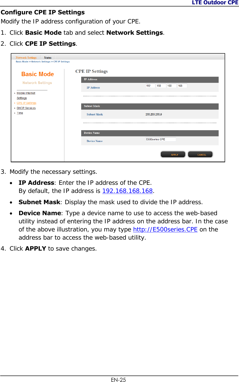
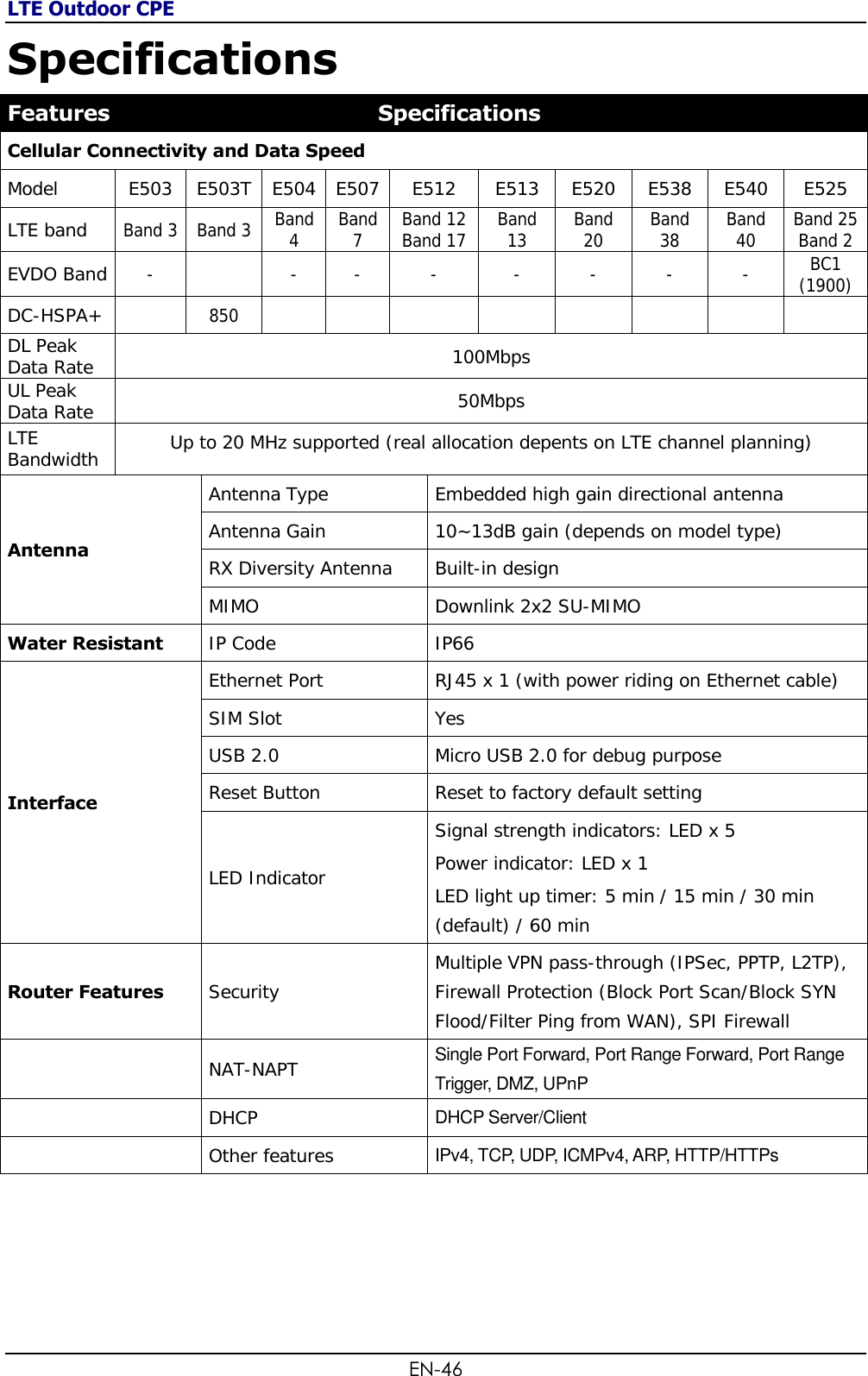
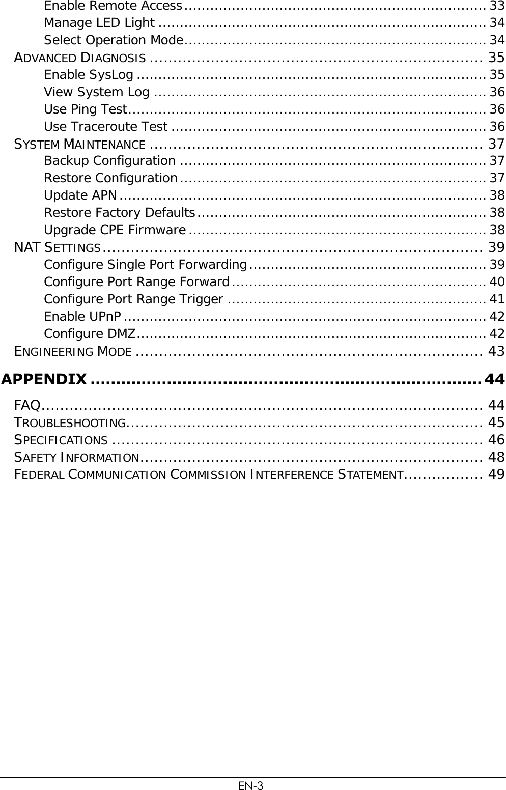
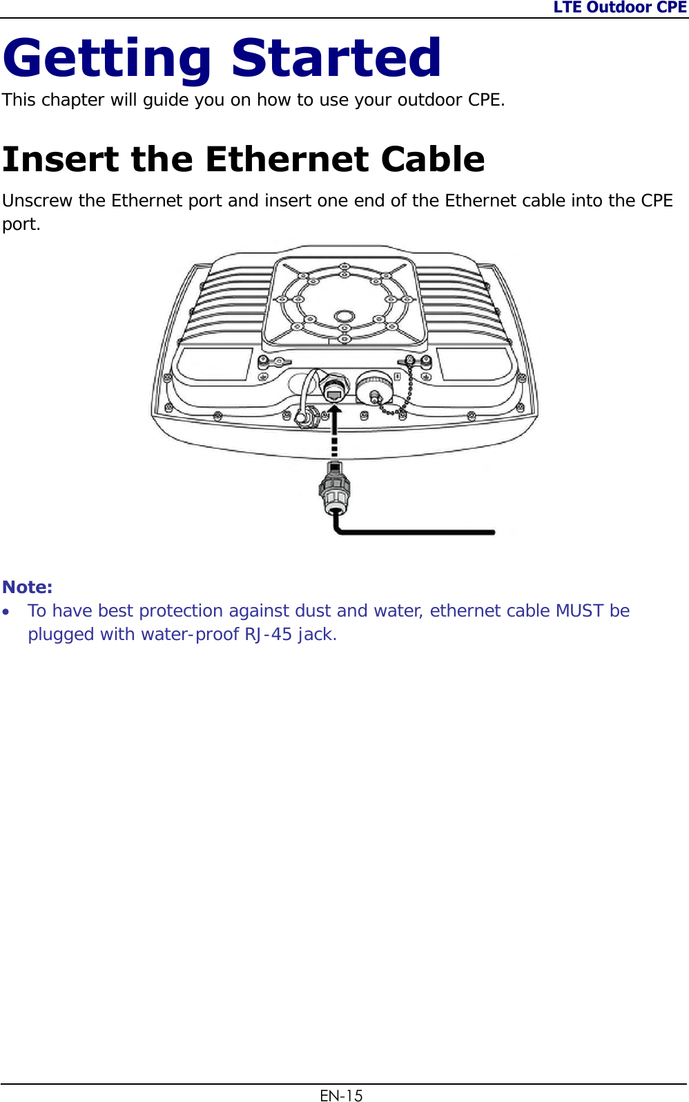
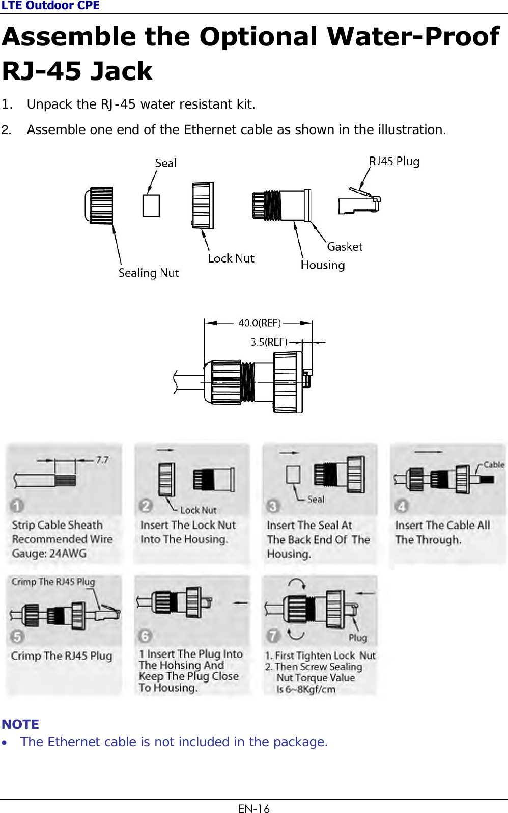
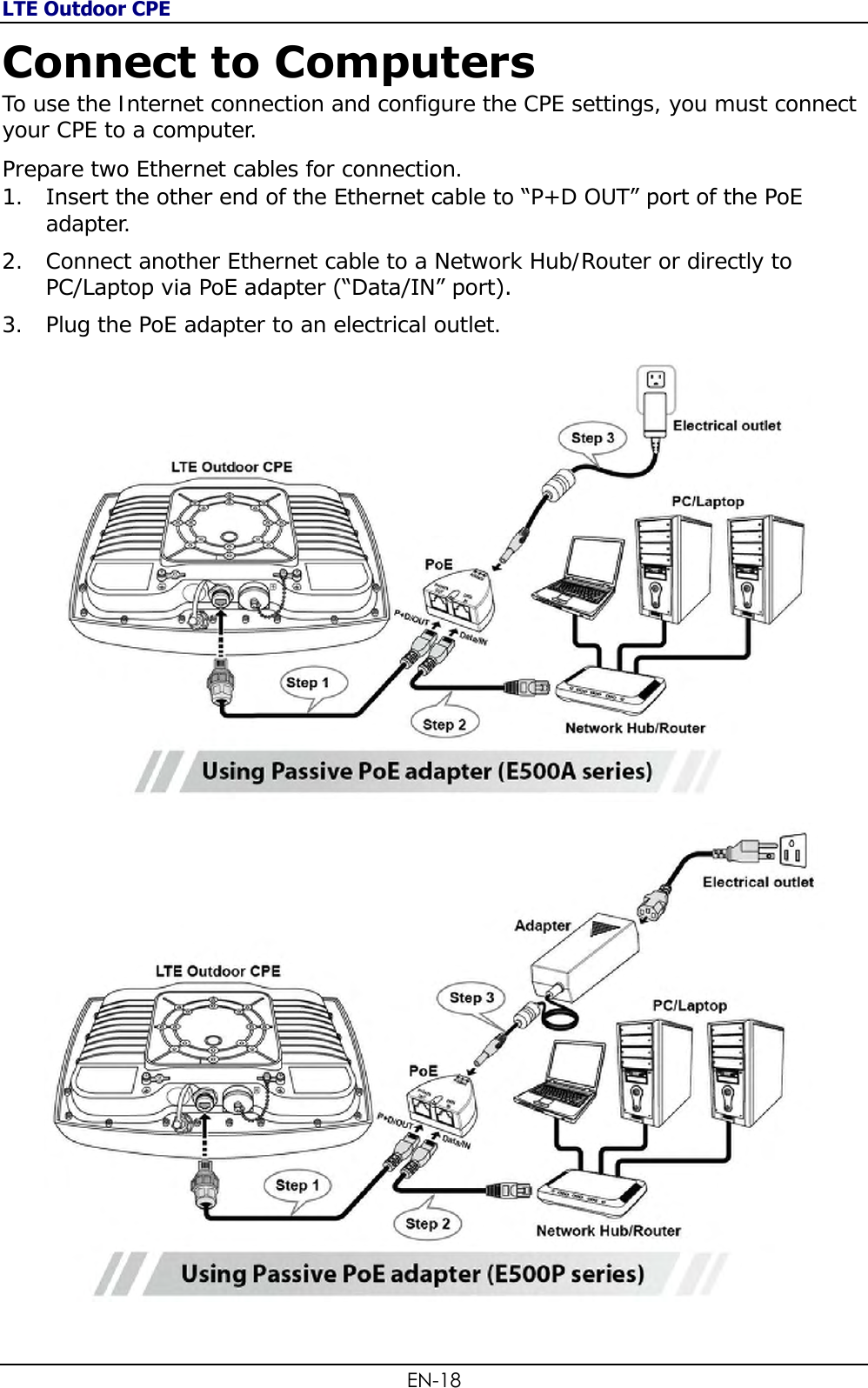
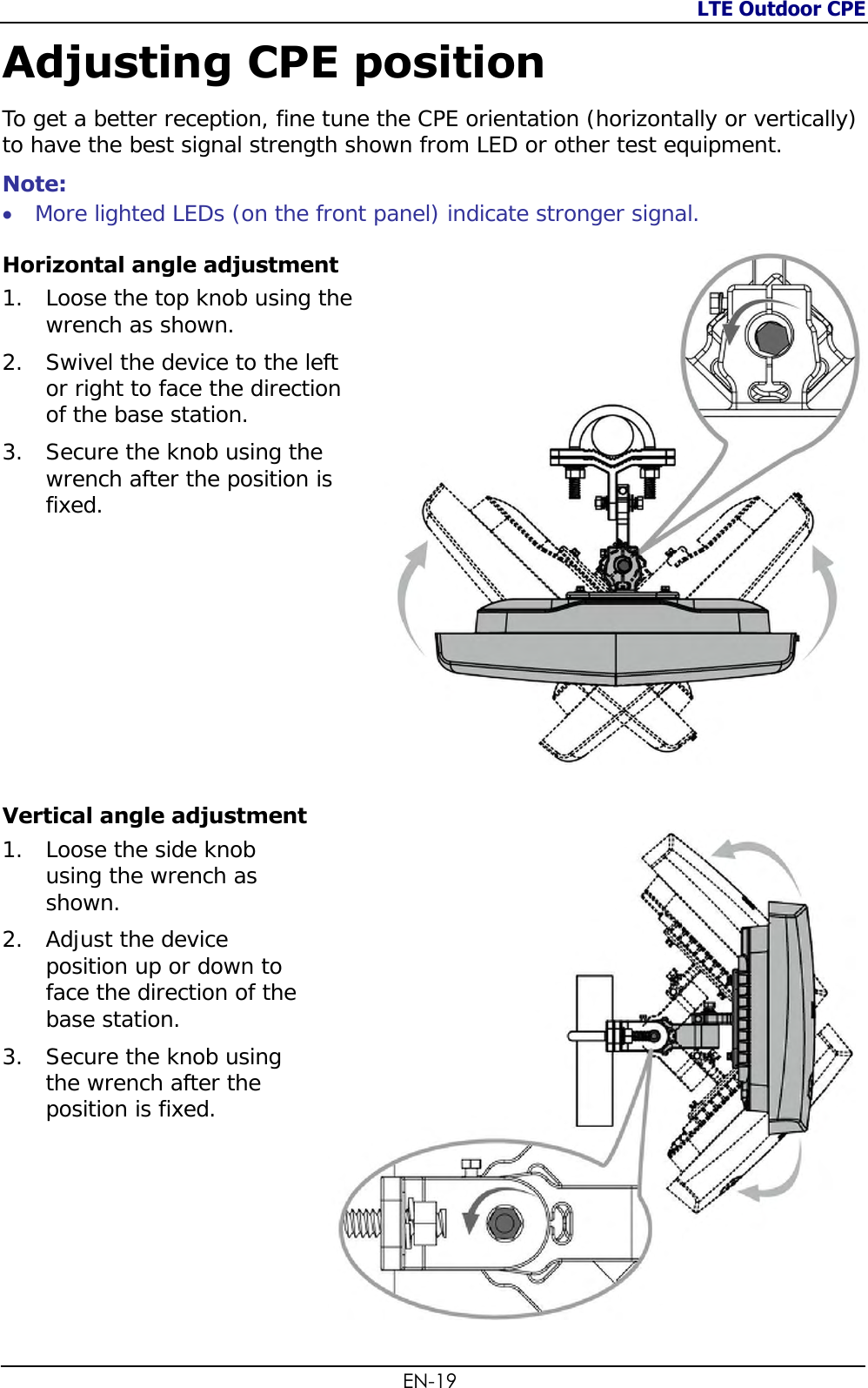
![EN-2 Table of Contents ABOUT THIS MANUAL ............................................................................ 4 PRODUCT OVERVIEW .............................................................. 5 FEATURES ......................................................................................... 5 PACKAGE CONTENTS ............................................................................ 5 PARTS AND FUNCTIONS ......................................................................... 6 NOTICE BEFORE INSTALLATION ................................................................ 7 IMPORTANT INSTALLATION CONSIDERATIONS ............................................... 8 INSTALL THE SIM CARD ....................................................................... 10 MOUNTING AND INSTALLATION .............................................................. 11 Mount Assembly package .................................................................. 11 Wall-mount Assembly ....................................................................... 12 Pole-mount Assembly ....................................................................... 13 GETTING STARTED ................................................................ 15 INSERT THE ETHERNET CABLE ............................................................... 15 ASSEMBLE THE OPTIONAL WATER-PROOF RJ-45 JACK .................................. 16 GROUNDING THE CPE ........................................................................ 17 CONNECT TO COMPUTERS .................................................................... 18 ADJUSTING CPE POSITION ................................................................... 19 Horizontal angle adjustment .............................................................. 19 Vertical angle adjustment ................................................................. 19 USING WEB-BASED MANAGEMENT ....................................... 20 CONFIGURE IP ADDRESS [FOR BRIDGE MODE ONLY] ..................................... 20 LOGIN............................................................................................ 22 BASIC NETWORK SETTINGS .................................................................. 24 Configure Mobile Internet Settings ..................................................... 24 Configure CPE IP Settings ................................................................. 25 Configure DHCP Services .................................................................. 26 Configure CPE Time .......................................................................... 27 STATUS INFORMATION ........................................................................ 28 View Internet Connection Info ........................................................... 28 View CPE Info .................................................................................. 29 View Traffic Info ............................................................................... 29 SIM/PIN SETTINGS ........................................................................... 30 Configure PIN .................................................................................. 30 Unlock SIM ...................................................................................... 31 SECURITY SETTINGS .......................................................................... 32 ADMINISTRATOR SETTINGS .................................................................. 33 Change Web Management Password .................................................. 33](https://usermanual.wiki/BandRich/P04E68/User-Guide-1905156-Page-2.png)


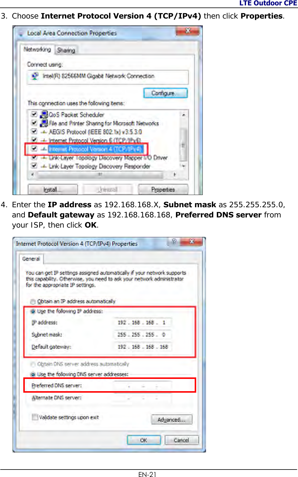
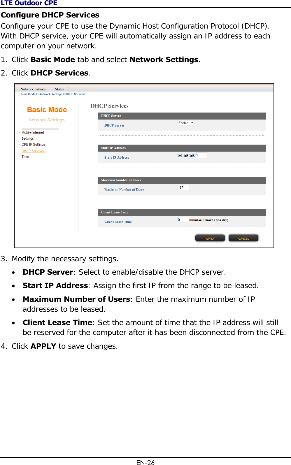
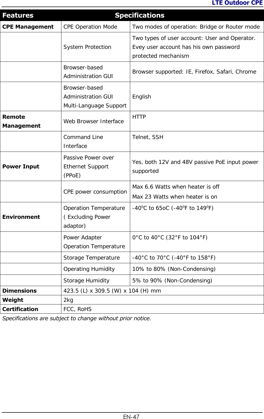
![LTE Outdoor CPE EN-20 Using Web-based Management This chapter will guide you on how to configure your CPE via the web-based utility. Configure IP address [for Bridge mode only] [Note] Configure IP address is not required under router mode. Please go to “Login” directly. Please follow below steps to configure IP address under bridge mode. 1. Go to Control Panel>Network and Internet>Network and Sharing Center to Change adapter settings. 2. Click the Local Area Connection>Properties.](https://usermanual.wiki/BandRich/P04E68/User-Guide-1905156-Page-20.png)