BandRich R505 LTE/HSPA+VoIP Router User Manual
BandRich Inc. LTE/HSPA+VoIP Router
UserManual.wiki
>
BandRich
>
R505 User Manual
>
User Manual
Contents
1.
User Manual
2.
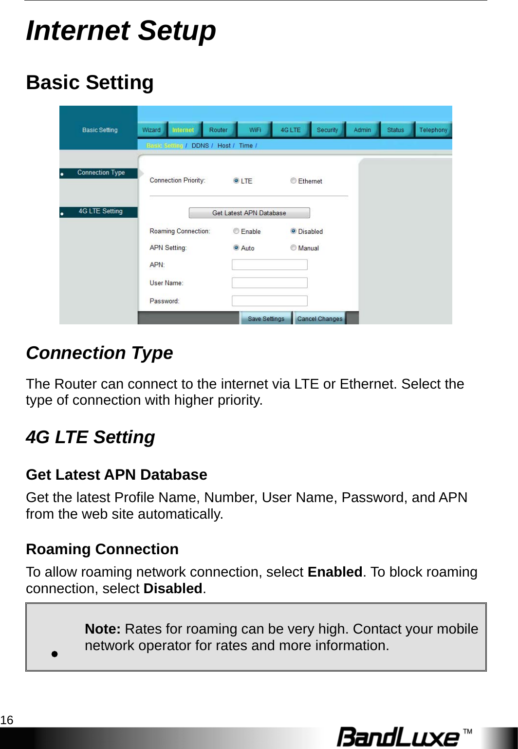
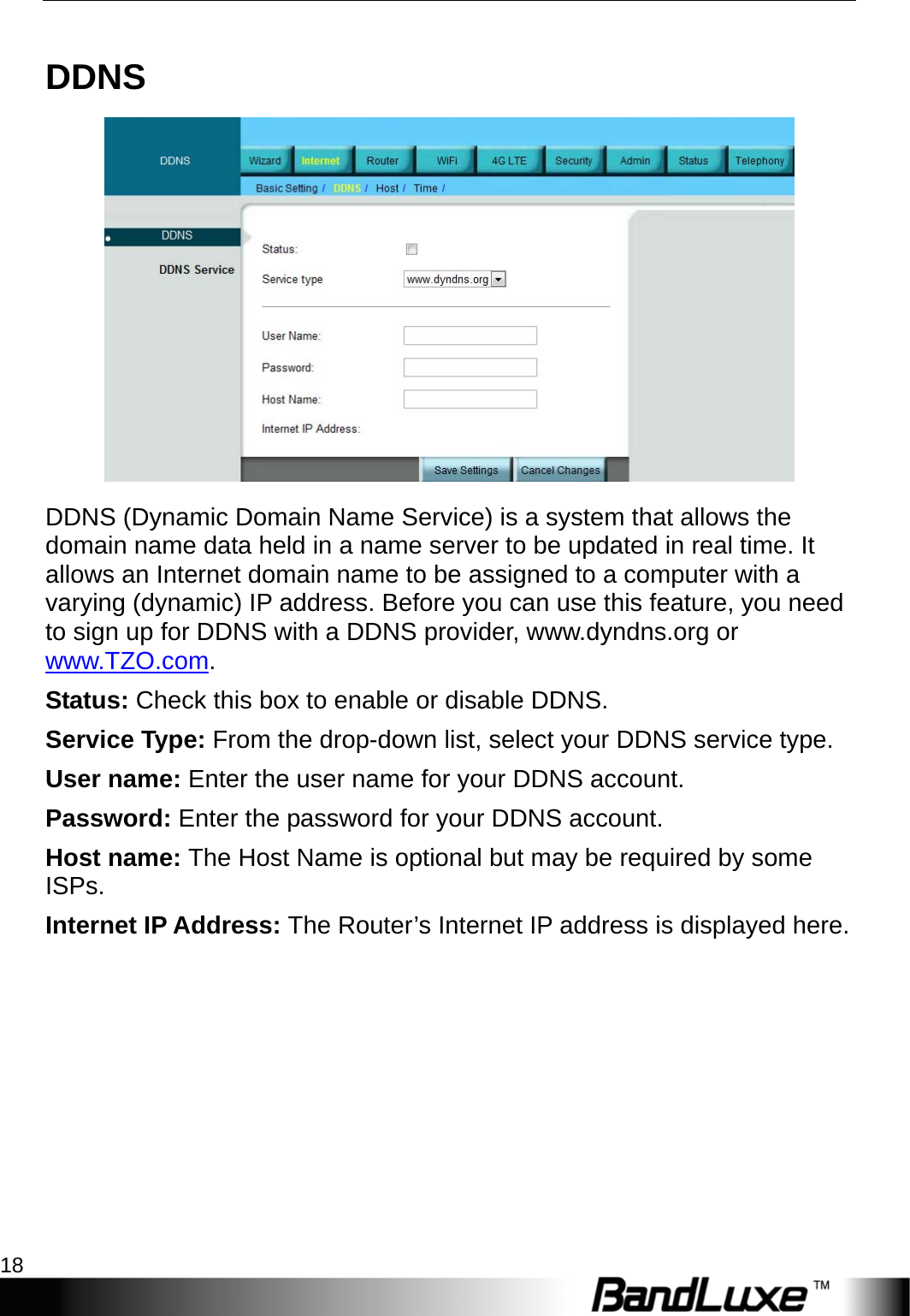
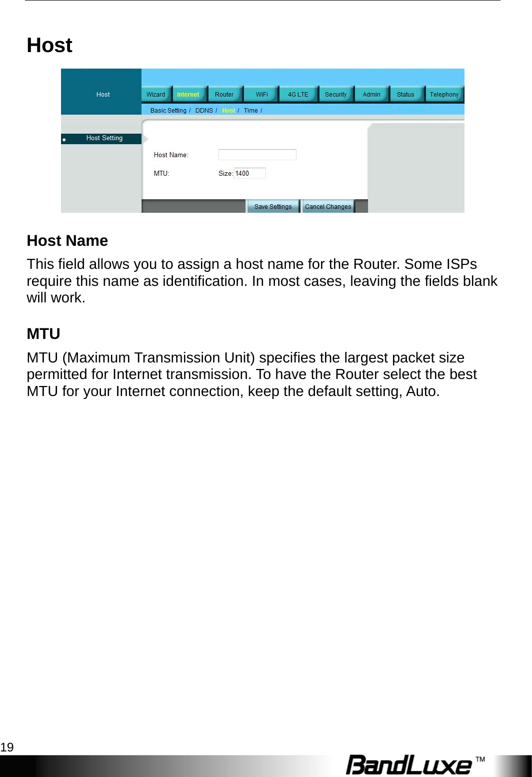
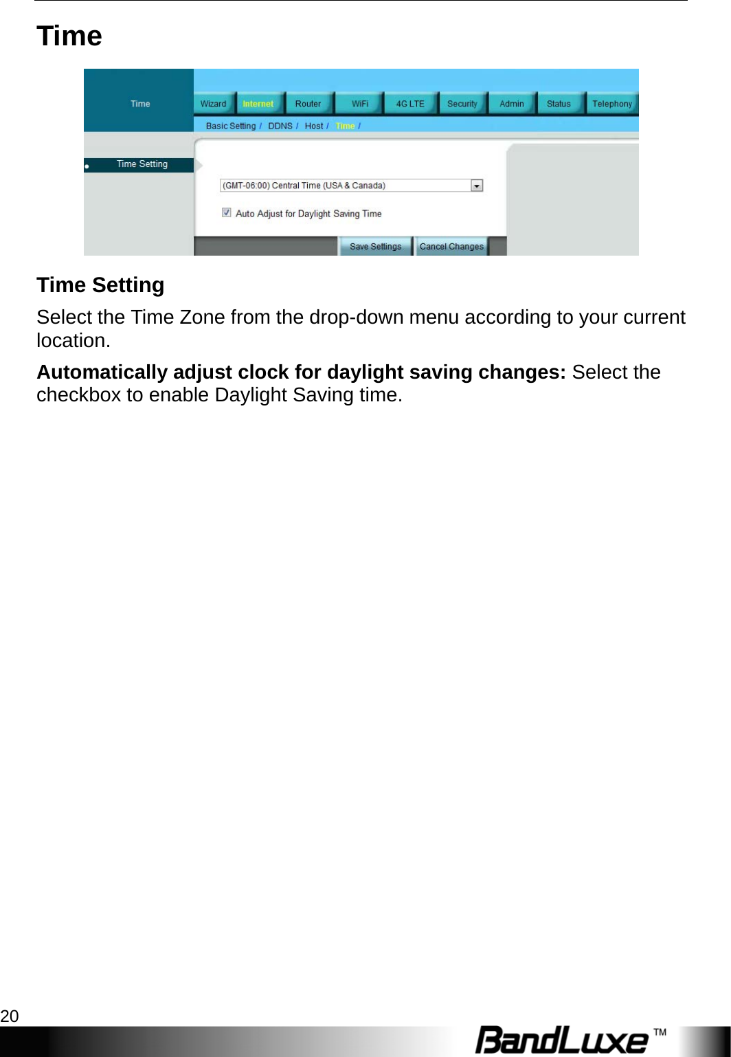
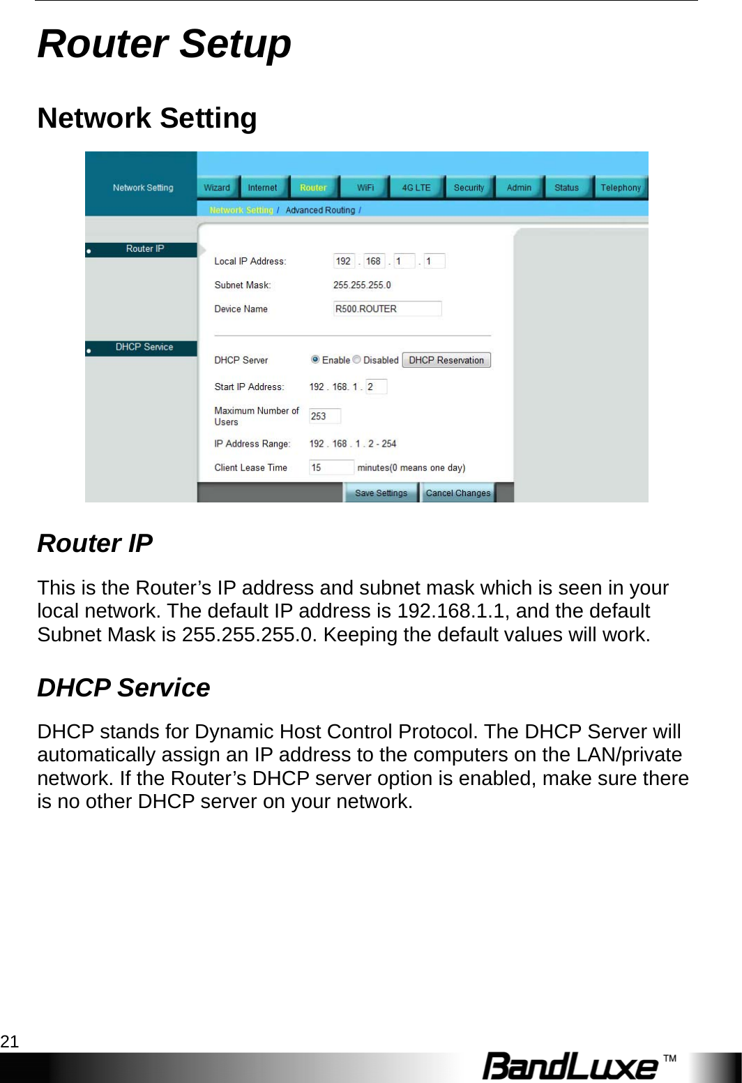
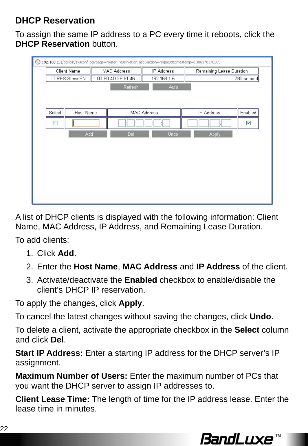
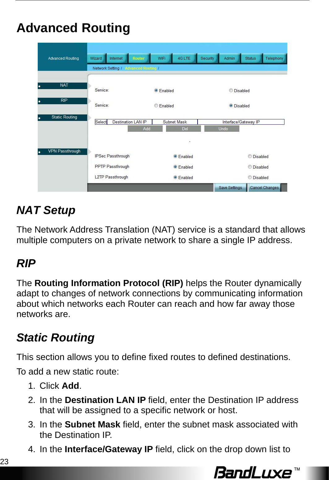
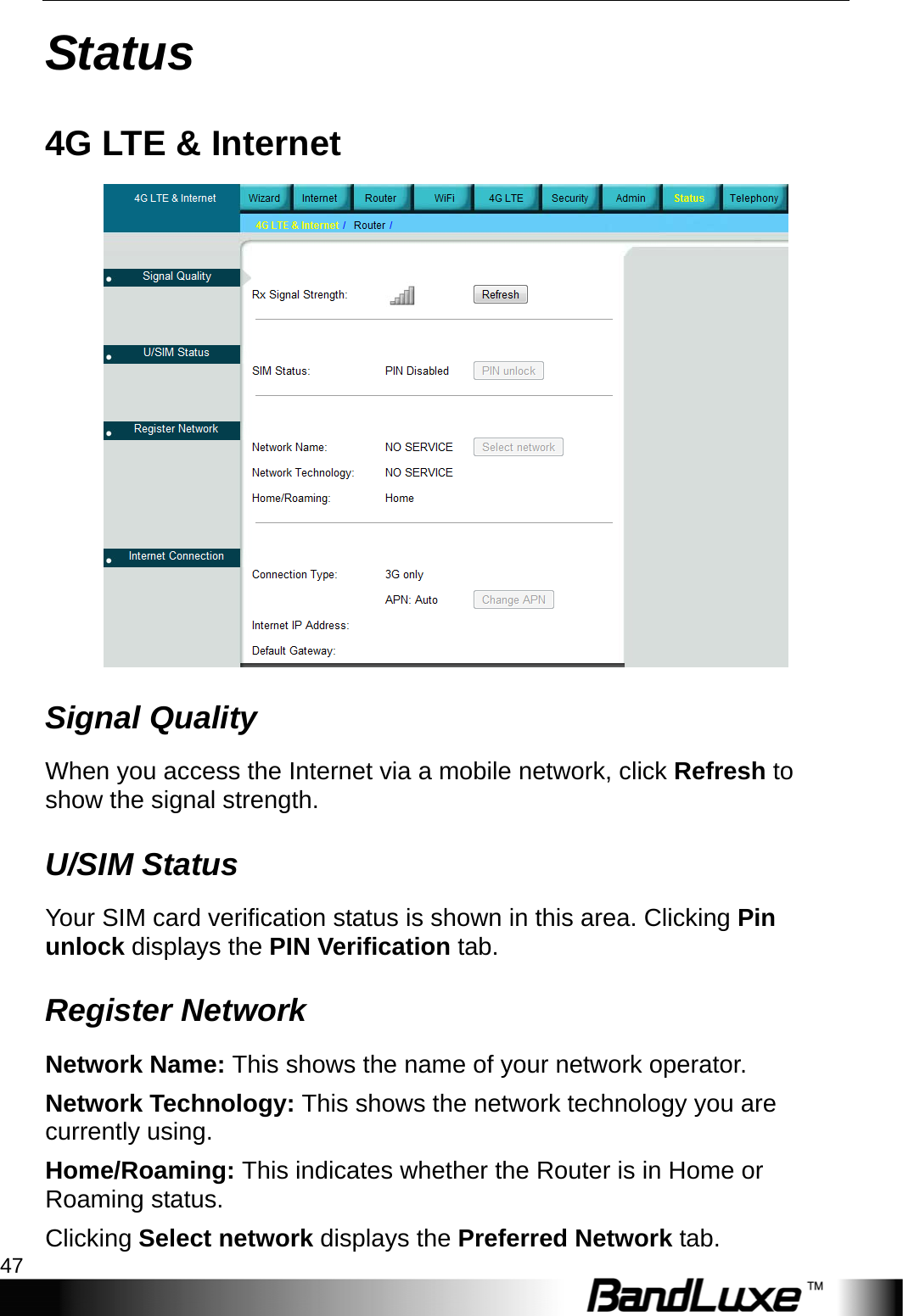
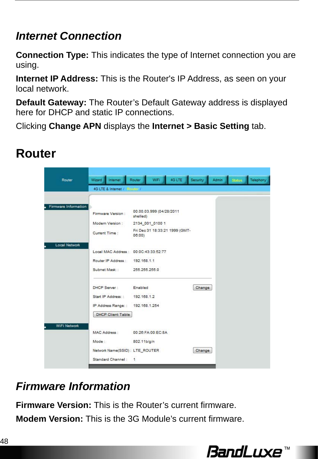
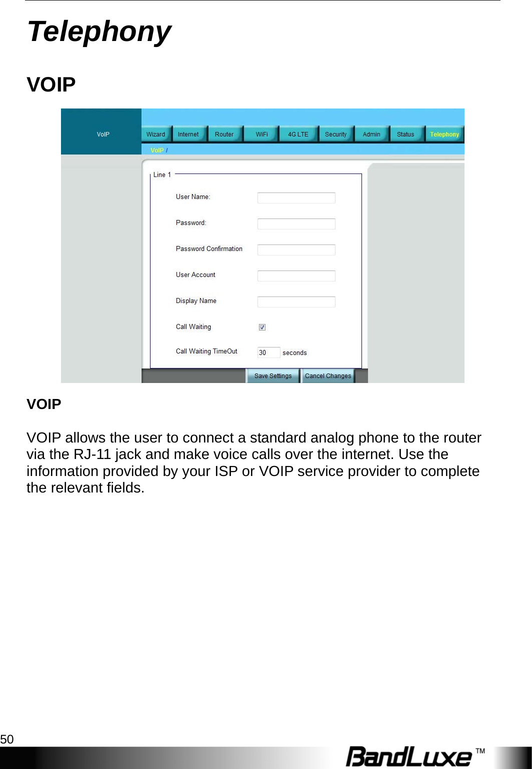
BandLuxe R500 Series User Manual_20120730
User Manual
Navigation menu
Upload a User Manual
Namespaces
Wiki Guide
HTML
PDF
Info
Views
User Manual
Discussion / Help
Navigation


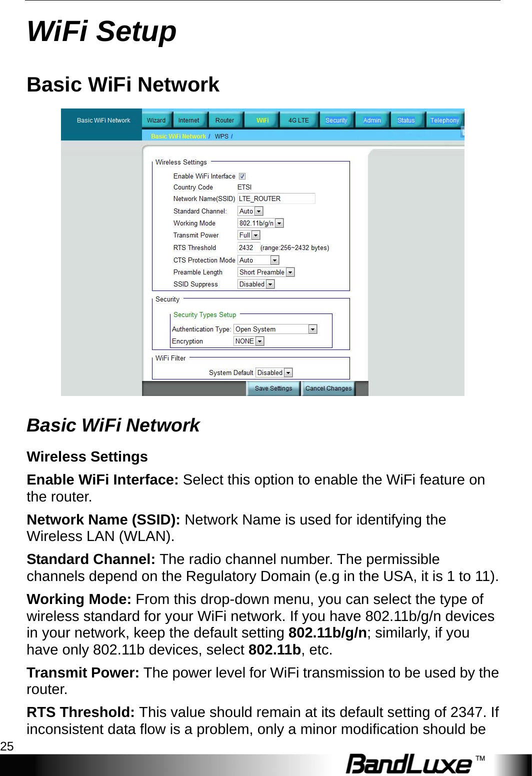


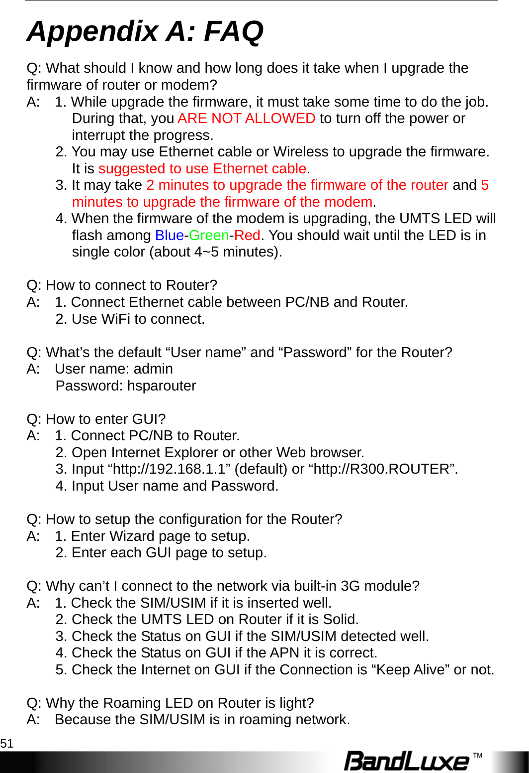
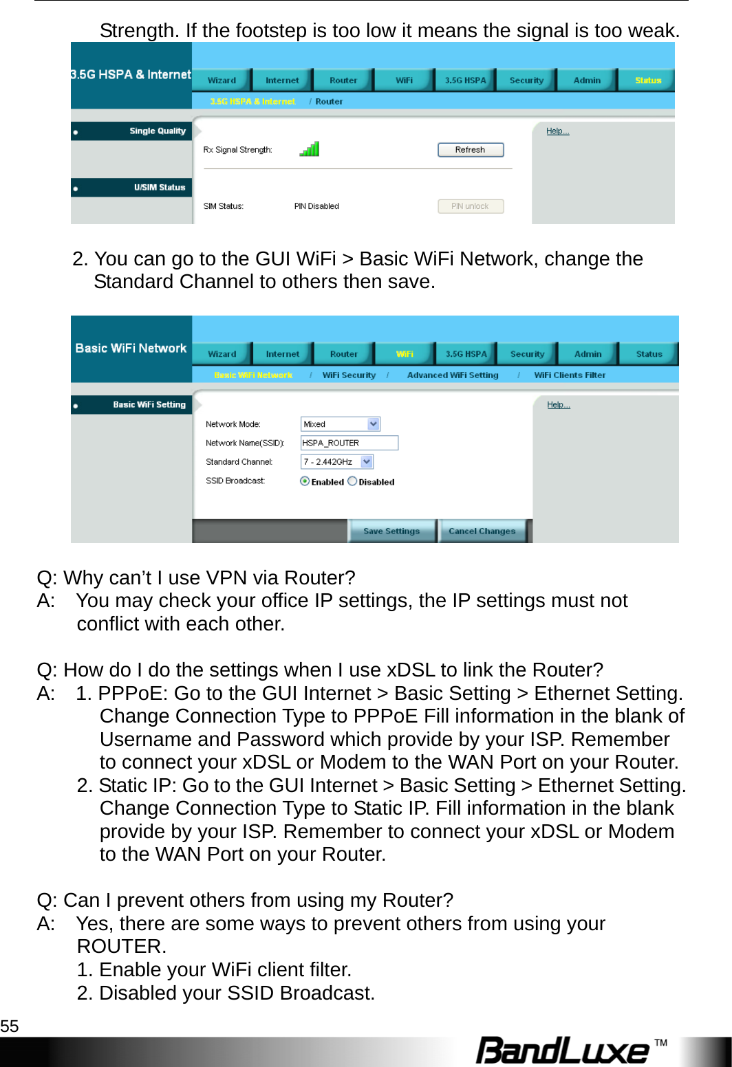

![Appendix B: Specification 60 Other Functions Automatic APN/ID/password settings Yes APN database update through browser-based GUI Yes Support FW version upgrade and downgrade Yes. Setup wizard behavior BandRich will define Setup wizard behavior System protection Password protected system reset to factory default, Password protected administrator and user access authority (provisioning, configuration, authentication). Status Indication LCD Display [Status Bar] • Cellular Signal Strength • Radio Technology • Wi-Fi, Ethernet, SIP status • Roaming indication [Main Screen] • Network Operator Name • Greetings • WPS Active Mode with count down timer Accessories Power adaptor Supported, Input - 100~240V 50~60Hz AC, output - tbd Environment Operation Temperature 0°C to 40°C (32°F to 104°F) Storage Temperature -20°C to 60°C (-4°F to 140°F) Operating Humidity 10% to 80% Non-Condensing Storage Humidity 5% to 90% Non-Condensing Certification FCC, GCF conformance RoHS](https://usermanual.wiki/BandRich/R505.User-Manual/User-Guide-1497303-Page-62.png)