BandRich R558C889 R558C Series LTE/HSPA + Wi-Fi Router User Manual BandLuxe FieldPerfect
BandRich Inc. R558C Series LTE/HSPA + Wi-Fi Router BandLuxe FieldPerfect
BandRich >
Contents
- 1. User Manual
- 2. Users Manual
User Manual

User
Manual
BandLuxe
R558C Series
LTE/HSPA+ Wi-Fi Router

1
Table of Contents
Features ............................................................................................................................ 3
Hardware Overview ........................................................................................................... 4
Status .............................................................................................................................. 12
Overview ........................................................................................................................... 13
System Log ....................................................................................................................... 14
Traffic Monitor ................................................................................................................... 15
Mobile Internet .................................................................................................................. 16
System ............................................................................................................................ 18
System .............................................................................................................................. 18
General Settings ...................................................................................................................... 18
Language and Style ................................................................................................................. 19
Administration ................................................................................................................... 20
Backup / Flash Firmware .................................................................................................. 21
Download backup .................................................................................................................... 21
Reset to defaults ...................................................................................................................... 22
Restore backup ........................................................................................................................ 22
Reboot............................................................................................................................... 23
Services .......................................................................................................................... 25
Dynamic DNS .................................................................................................................... 25
Network ........................................................................................................................... 26
Interfaces .......................................................................................................................... 26
Mobile Internet .................................................................................................................. 26
Network Settings ...................................................................................................................... 27
Auto APN Information .............................................................................................................. 28
APN Profile Settings ................................................................................................................ 28
Reset Modem ........................................................................................................................... 28
Scenario 1: No mobile internet service .................................................................................... 29
Scenario 2: Mobile internet service pending ............................................................................ 29
Scenario 3: Mobile internet service enabled ............................................................................ 30
Scenario 1: SIM lock absent .................................................................................................... 32
Scenario 2: SIM lock present ................................................................................................... 32
Router ............................................................................................................................... 34
Router IP .................................................................................................................................. 34
DHCP Service .......................................................................................................................... 35
Active DHCP Leases ............................................................................................................... 36
Static Leases ........................................................................................................................... 36
Static Routing ........................................................................................................................... 37

2
Routing and Redirection Service ............................................................................................. 38
VPN Passthrough .................................................................................................................... 38
WiFi ................................................................................................................................... 39
Advanced Settings ................................................................................................................... 42
General Setup .......................................................................................................................... 43
Wireless Security ..................................................................................................................... 43
MAC-Filter ................................................................................................................................ 47
Advanced Settings ................................................................................................................... 48
WPS Settings ........................................................................................................................... 49
Firewall .............................................................................................................................. 51
Single Port Forward ................................................................................................................. 51
Port Range Forward ................................................................................................................. 53
Port Trigger .............................................................................................................................. 55
Security Filter ........................................................................................................................... 57
Network Filtering ...................................................................................................................... 60
UPNP ................................................................................................................................ 62
Advanced ........................................................................................................................ 63
Diagnostics........................................................................................................................ 63
Ping .......................................................................................................................................... 63
Traceroute ................................................................................................................................ 64
NS Lookup ............................................................................................................................... 64
SMS ................................................................................................................................ 64
New SMS .......................................................................................................................... 65
Inbox ................................................................................................................................. 67
Outbox............................................................................................................................... 68
Draft .................................................................................................................................. 69
Setting ............................................................................................................................... 72
Setting ...................................................................................................................................... 72
Backup ..................................................................................................................................... 72
Help ................................................................................................................................. 74
Logout ............................................................................................................................. 74
Europe – EU Declaration of Conformity .......................................................................... 88
Federal Communication Commission Interference Statement ........................................ 90
Glossary .......................................................................................................................... 92
Package Contents
3
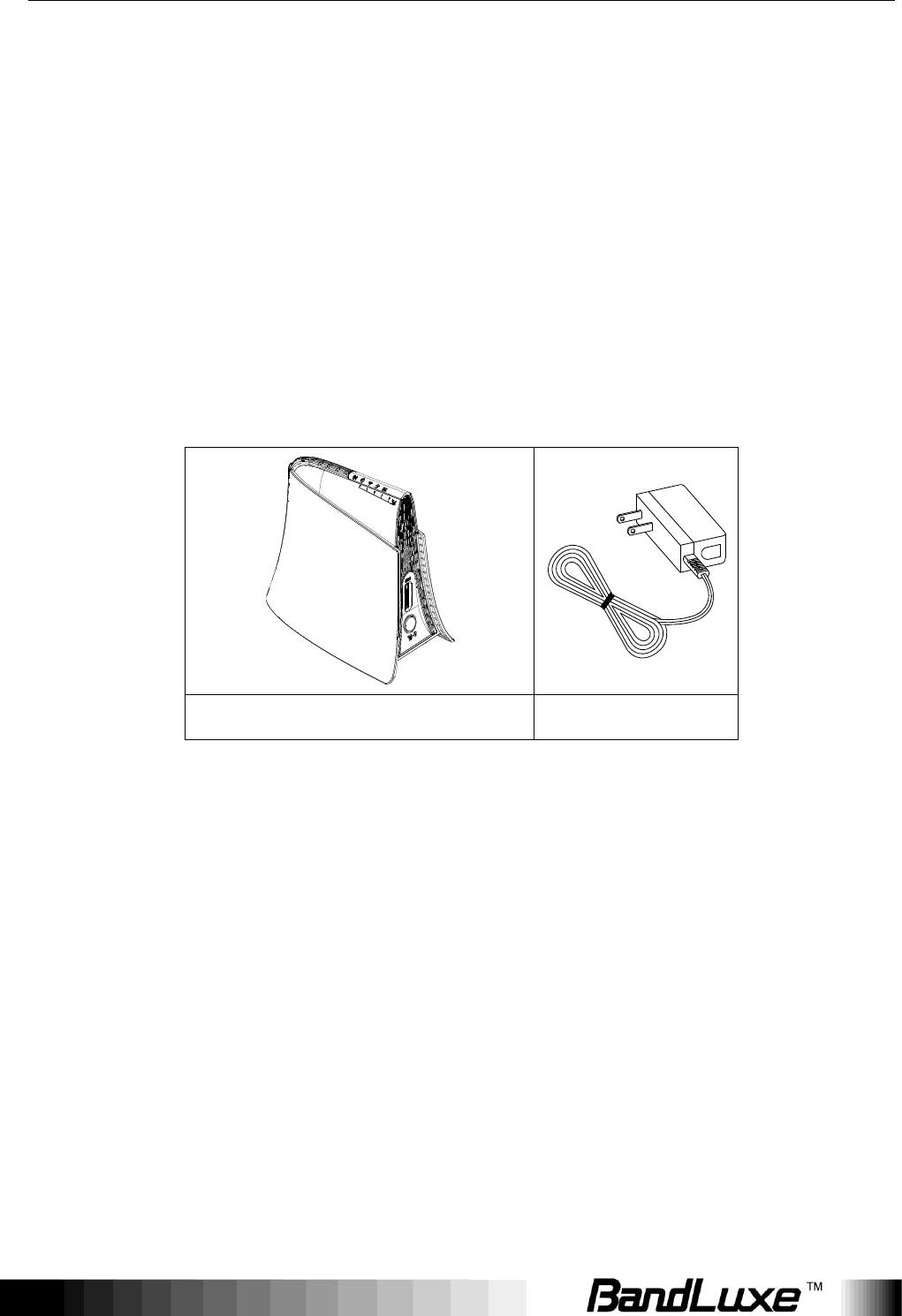
Package Contents
Thank you for your purchase of this LTE/HSPA+ WiFi Router. This product is
designed to access the Internet via 4G technology and share the bandwidth
through a Wi-Fi network. It is easy to configure and operate even for
non-technical users. This manual contains instructions for installing and
configuring the product. Read the manual carefully before you use the product,
so that you can fully exploit the product functions.
Package Contents
R558C series LTE Home Router
Power Adapter
Features
R558C series LTE Home Router
Wi-Fi Protected Setup (WPS) Support
Uplink up to 50 Mbps
Downlink up to 100Mbps
Supports Wi-Fi 802.11 b/g/n
Supports LAN Ethernet Ports
Dual embedded cellular antenna (for diversity)
Package Contents
4
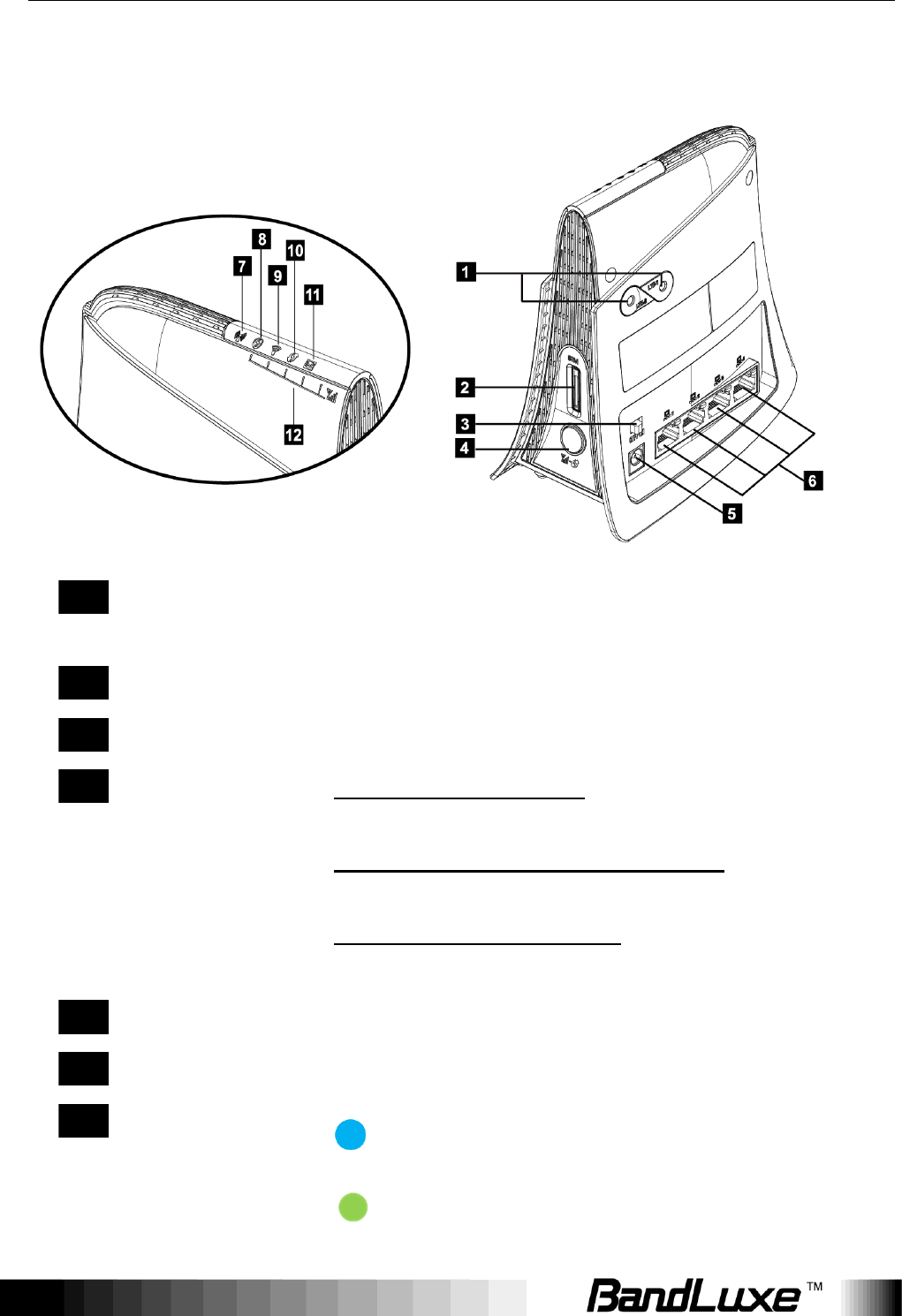
Hardware Overview
1
4G External
Antenna Ports
Connect 4G External Antennas if needed.
2
SIM Card Slot
Insert SIM/USIM. Push-push type.
3
Power Switch
Switch on/off the router.
4
Signal Strength
LED/WPS/Reset
button
Short press (1 second): Enable signal strength
indication.
Press for 3 seconds (< 10 seconds): Active
WPS.
Long press (>10 seconds): Restore to factory
default settings.
5
Power Receptor
Receptor for the Power Adapter.
6
LAN Port
Connect a LAN device as needed.
7
Network Status
LED
(Blue) 4G LTE
(Green) 3G HSPA+/HSPA/UMTS/EVDO

Package Contents
5
(Red) No signal, SIM error, Service failure
(no IP) ; Flashing when firmware is being
updated
8
Power LED
Solid when power is on / Signal Strength LED
9
WiFi LED
Solid when WiFi is on; Flashing during WiFi data
transmission / Signal Strength LED
10
WPS LED
Flashing when WPS is in use /Signal Strength
LED
11
SMS LED
Flashing when there is unread SMS / Signal
Strength LED
12
Signal Strength
Bars Reading
Short press on Signal LED/WPS/Reset button,
Signal Strength LEDs show current signal
strength.
Strong signal:
Poor signal:
*To send and receive SMS may incur additional fees.
Contact your carrier for information about service availability and plans.
Installation
6
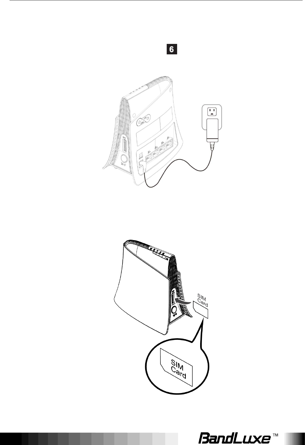
Installation
Connect the power Adapter to the Router( ) and connect it to an outlet.
Insert your SIM card into the slot on the Router, making sure the SIM card
orientation matches the SIM card slot, as shown in the picture.

Installation
7
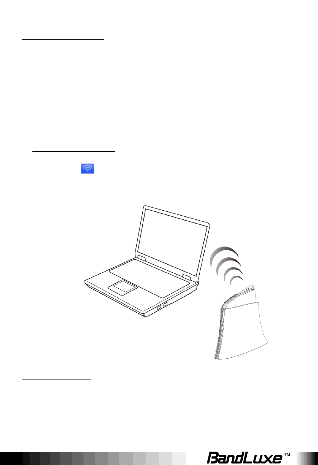
Slide the power switch ( ) to ON.
One of the following two methods can be chosen to link your PC with the
Router.
Installation
8
Wireless Connection (for Windows)
To connect your PC to the Router via WiFi, in Microsoft Windows, go to
Control Panel > Network Connections. Right click on Wireless Network
Connection and choose View Available Wireless Networks. Select
default SSID [BR_LTE_xxxx] and enter default password (WPA key, refer
to label on the Router‟s backside). Click Connect. The “xxxx”
corresponds with the last 4 digits of MAC address.
Wireless Connection (for Mac)
To click the on the upper side of the screen to view available
wireless networks.
Wired Connection
To connect your PC to the Router via an Ethernet cable, connect one end
of the cable to one of the four LAN ports on the Router, and another end
of the cable to an Ethernet port on your computer.
Installation
9
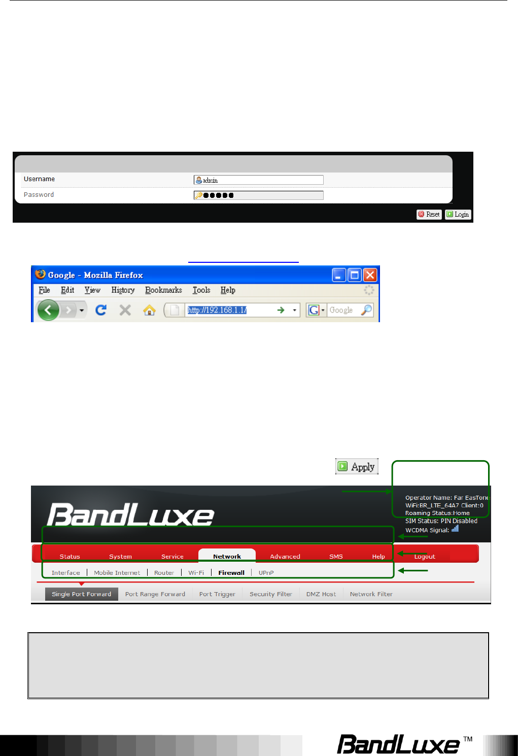
The router uses a web-based configuration utility. To access the configuration
utility, open a browser (ex: Mozilla, Firefox, etc.) and enter the IP address
(http://192.168.1.1) for the Router in your browser‟s address bar.
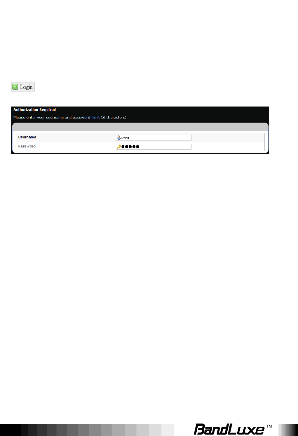
Enter the router Username (admin) and Password (admin), and then click
.
Using Web-based Management
10
Using Web-based Management
This chapter will guide you on how to configure your router via the
web-based utility.
Login
1. Launch a web browser (e.g Mozilla Firefox).
2. In the address bar, enter http://192.168.1.1, then press Enter.
3. On the opening screen, enter the username (admin) and password
(admin).
4. Click Login.
5. Click one of the menu, submenu, and/or setting tabs to configure the system.
Additionally, the status area displays current wireless network information
and setting-related messages (e.g. the message Unapplied Change
appears whenever new settings are temporarily stored in the router without
being applied, which will remind you to click the button).
Note:
If SIM Card‟s PIN verification is needed, select Network > Mobile
Internet > U/SIM PIN Management.
Enter the PIN code into text box of “PIN Code Verification”. Click Verify.
m
me
en
nu
u
s
su
ub
bm
me
en
nu
u
s
se
et
tt
ti
in
ng
g
status area

Using Web-based Management
11
Mobile internet access will be enabled shortly after.

Using Web-based Management
12
Status
This menu displays various status of the router. The associated submenu items
are: Overview, System Log, VnStat Traffic Monitor, and Mobile Internet.
Using Web-based Management
13
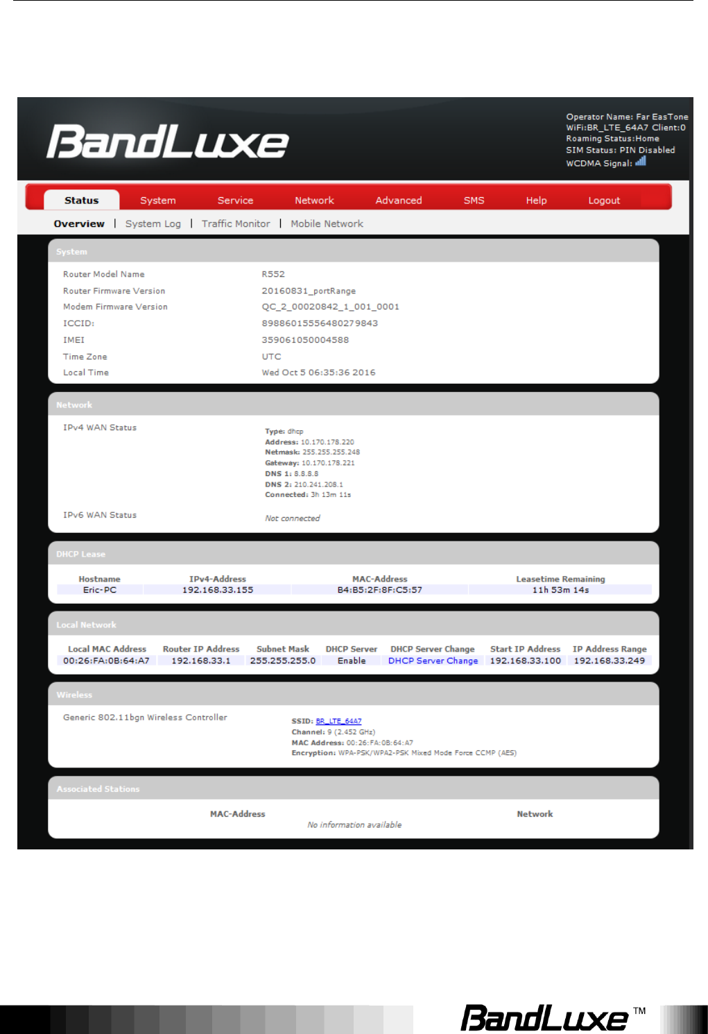
Overview
The Overview submenu renders complete statistics for the router.
Using Web-based Management
14
System
Displays system information: router model name, router firmware version,
modem firmware version, phone number (MDN), ICCID, MIN (MSID), PRL
version, IMEI, MEID, and local time.
Network
Displays current network connection information of IPv4 WAN and/or IPv6
WAN: type of network assignment (e.g. DHCP), network address, netmask,
gateway, DNS addresses 1 & 2, and time connected since the establishment of
the current mobile internet connection.
DHCP Leases
Display DHCP lease information for each client: hostname, IPv4 address, MAC
address, and lease time remaining.
Local Network
Displays local network information: local MAC address, router IP address,
subnet mask, DHCP server, DHCP server change, start IP address, IP and
address range
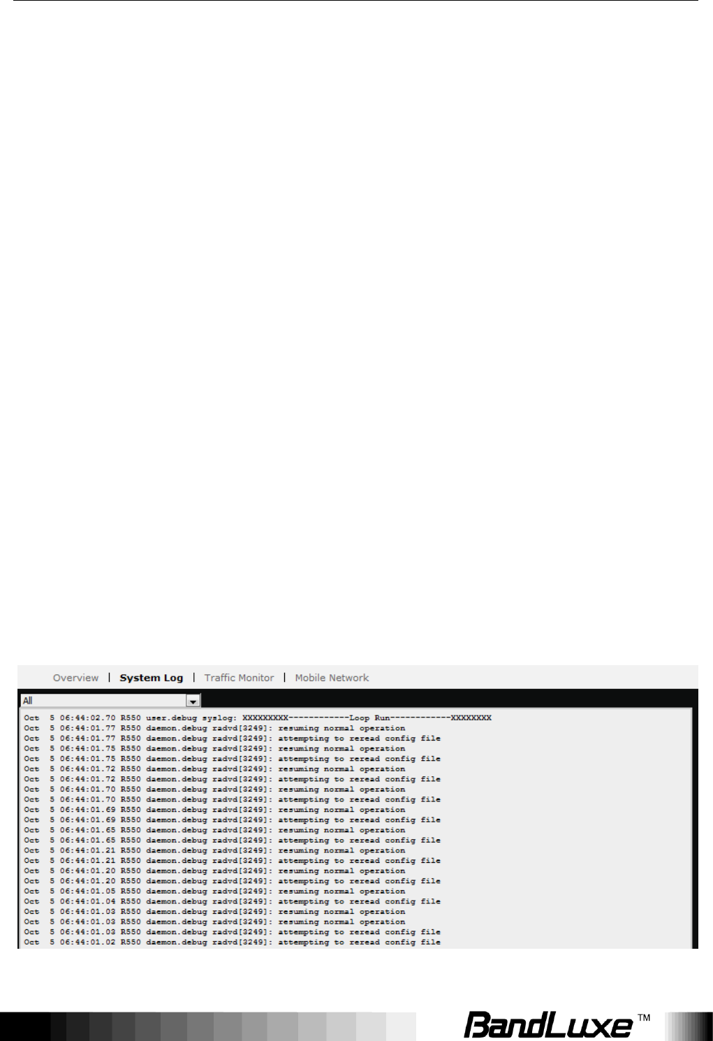
System Log
The System Log submenu tracks system activities after power on.
Using Web-based Management
15
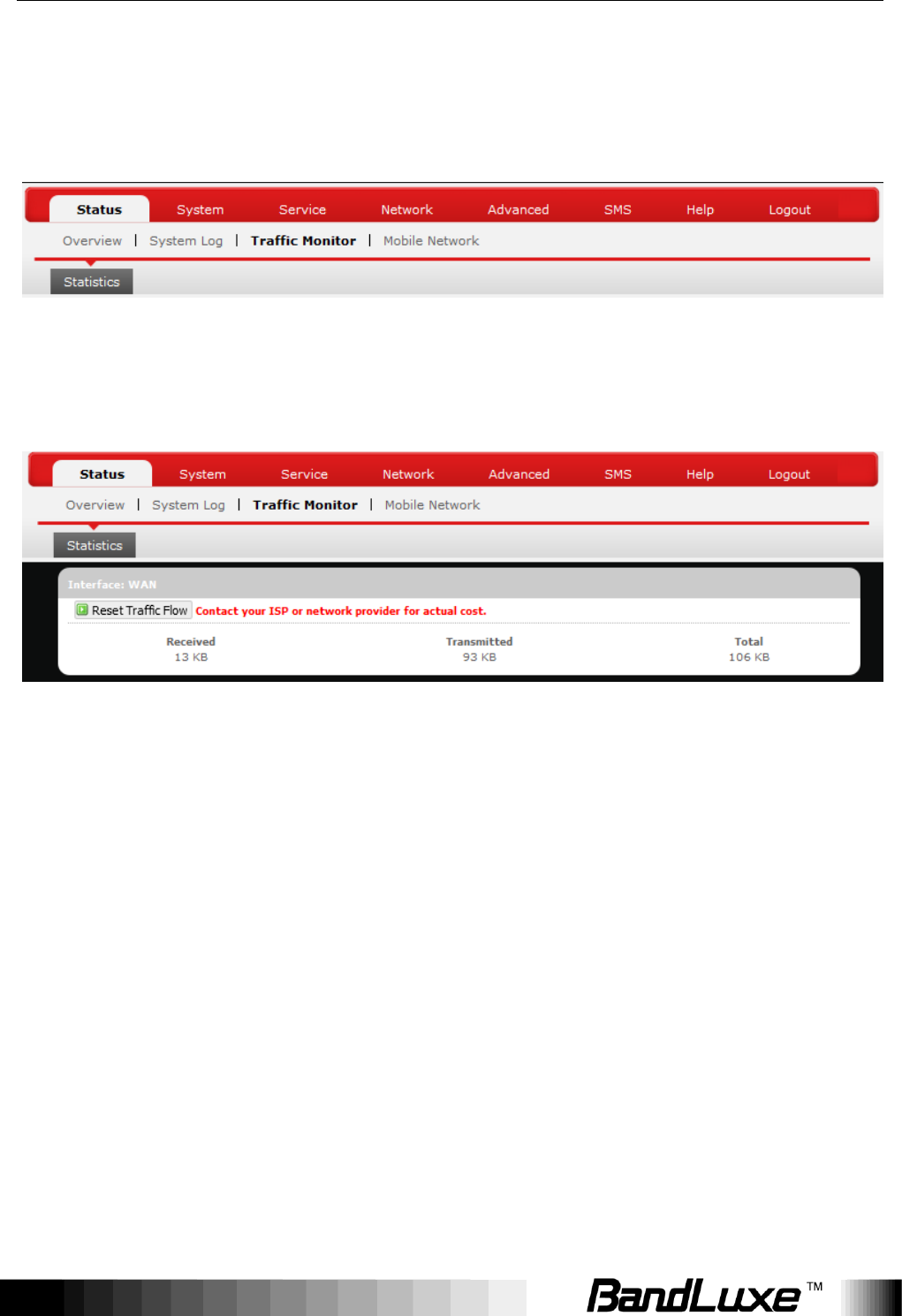
Traffic Monitor
Statistics
Rest Traffic Flow: Click to discard previous network history log and start a new.
Using Web-based Management
16
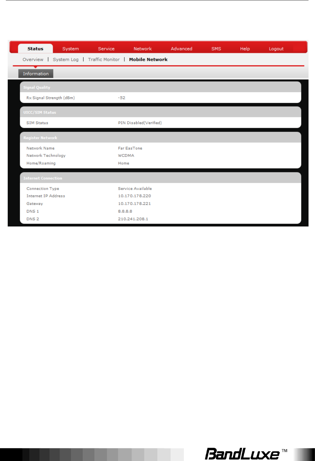
Mobile Internet
The Mobile Internet submenu displays mobile internet statistics.
Signal Quality
Displays signal strength of current mobile internet connection in dBm.
UICC/SIM Status
Displays current SIM card status:
a) Read SIM Fail – No valid SIM card is inserted
b) PIN Disable(Verified) – PIN protection is disabled while the SIM card status
is verified; mobile internet service is available with this status.
c) PIN Enable(No Verified/Retries:#) – PIN protection is enabled while the SIM
card verification is pending (whereas # is the number of allowed PIN
verifications remaining before SIM lock occurs).
d) PIN Enable(Verified) – PIN protection is enabled while the SIM card status is
verified; mobile internet service is available with this status.

Using Web-based Management
17
Registered Network
a) Network Name – name of your mobile internet service provider
b) Network Technology – mobile internet communication signal type.
Ex: WCDMA (3G) and LTE (4G).
c) Home/Roaming – displays current network roaming status:
Home indicates mobile internet connection to the home location where the SIM
card service is registered. Roaming indicates the extended mobile internet
connection service in a location different from the home location where the SIM
card service is registered. An example of roaming is when you travel abroad.
Internet Connection
Displays information of current internet connection:
Connection Type, Internet IP Address, Gateway, and DNS 1/2.
Using Web-based Management
18
System
This menu is for system information and configurations.
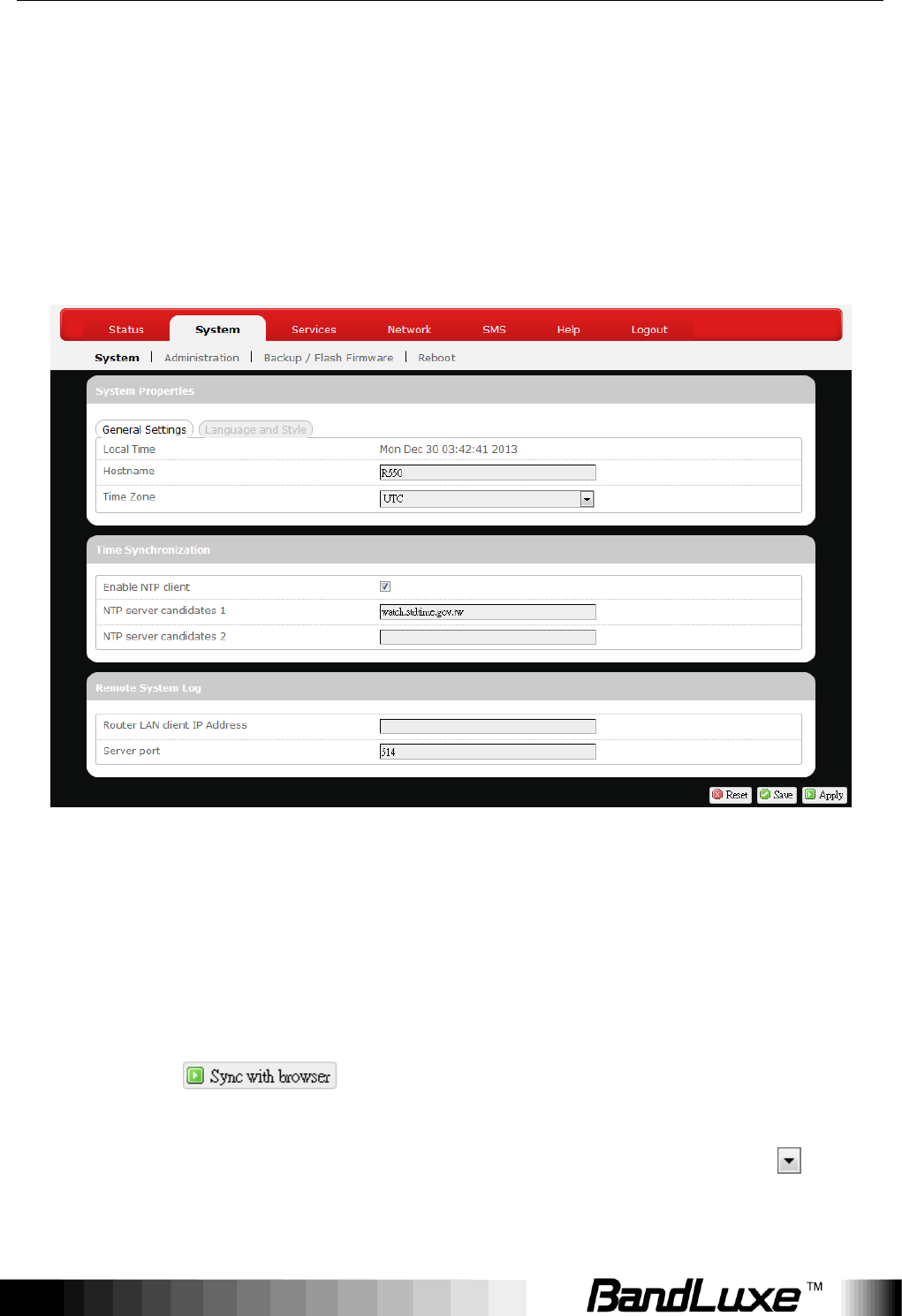
System
System Properties
Click either the “General Settings” or “Language and Style” tab to configure
their respective settings.
General Settings
Local Time – Displays current local time. To synchronize local time with the
browser, click .
Hostname – Enter the desired hostname in this check field.
Time Zone – Sets the time zone associated with this router. Click on and
select the desired region.

Using Web-based Management
19
Language and Style
Language – Sets the desired display language and style of the router. Click
and select the desired display language and style.
Time Synchronization
Enable NTP client: Click the checkbox to enable/disable. With this option
enabled, two more options will appear– “Provide NTP server” and “NTP server
candidates”.
NTP server candidates 1/2: Enter the desired server candidates here.
Remote System Log
Router LAN client IP address: Displays the client IP address of the router
LAN.
Server port: Displays port number of the server.
Using Web-based Management
20
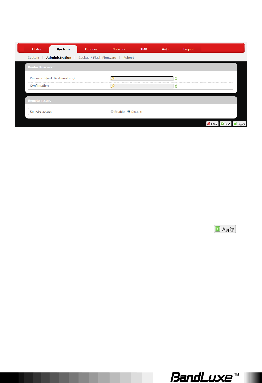
Administration
Router Password
Login password of the router can be changed here. Enter the new password in
the „Password‟ field, and enter the same password once again in the
„Confirmation‟ field.
Remote Access
This field specifies whether or not to allow remote access of this router.
After changing password and/or specifying remote access, click . The
screen will display a confirmation message after successful password change.
Using Web-based Management
21
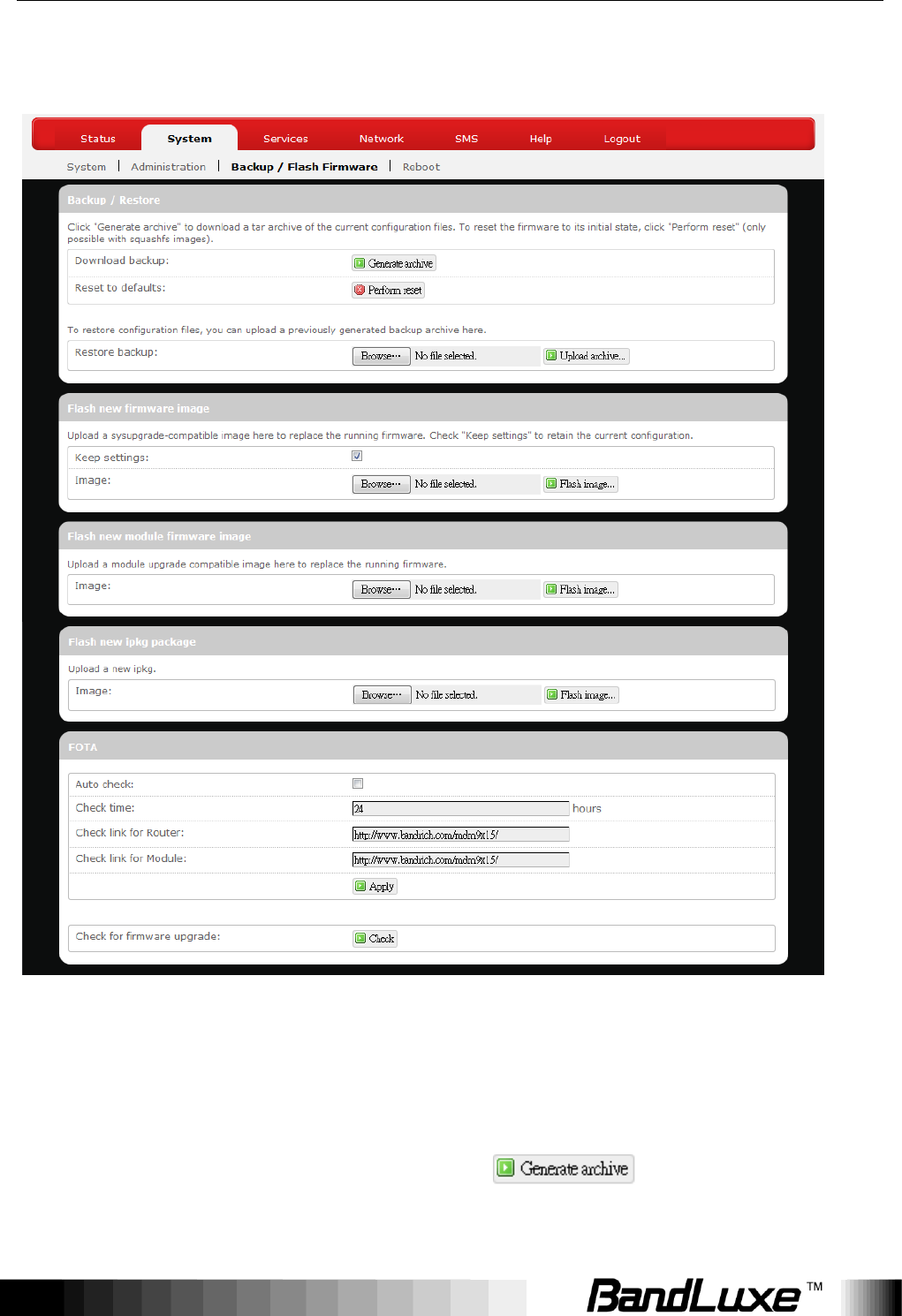
Backup / Flash Firmware
Backup / Restore
Download backup
Here you can backup all current settings of the router to a TAR archive file on
your computer or mobile device. Just click . A dialog window will
prompt you to open or save the archive file. Depending on the browser that you
Using Web-based Management
22
are using, the TAR file may be saved in the system download folder or a
location of your choice.
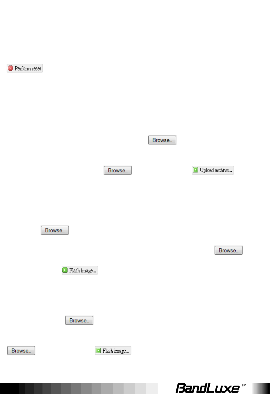
Reset to defaults
Here you can restore the router to its original factory settings. Just click
, and a dialog message will appear to indicate the factory reset
process. After completion of the reset process, the router will automatically
reboot and return to its initial login prompt.
Restore backup
Here you can restore router settings previously saved as a TAR archive file on
your computer or mobile device. Just click to find and select the
previously saved TAR archive file, and then click „Open‟. Confirm that the TAR
filename appears beside the button and click . The
system will reboot after completion of backup restoration.
Flash new firmware image
This option allows you to upgrade this router with the updated firmware image.
Just click to find and select the firmware image file, and then click
„Open‟. Confirm that the firmware filename appears beside the
button and click . The system will reboot after successful upgrade.
Flash new module firmware image
This option allows you to upgrade this router with the updated module firmware
image. Just click to find and select the firmware package file, and
then click „Open‟. Confirm that the firmware filename appears beside the
button and click . The system will reboot after successful
upgrade.
Using Web-based Management
23
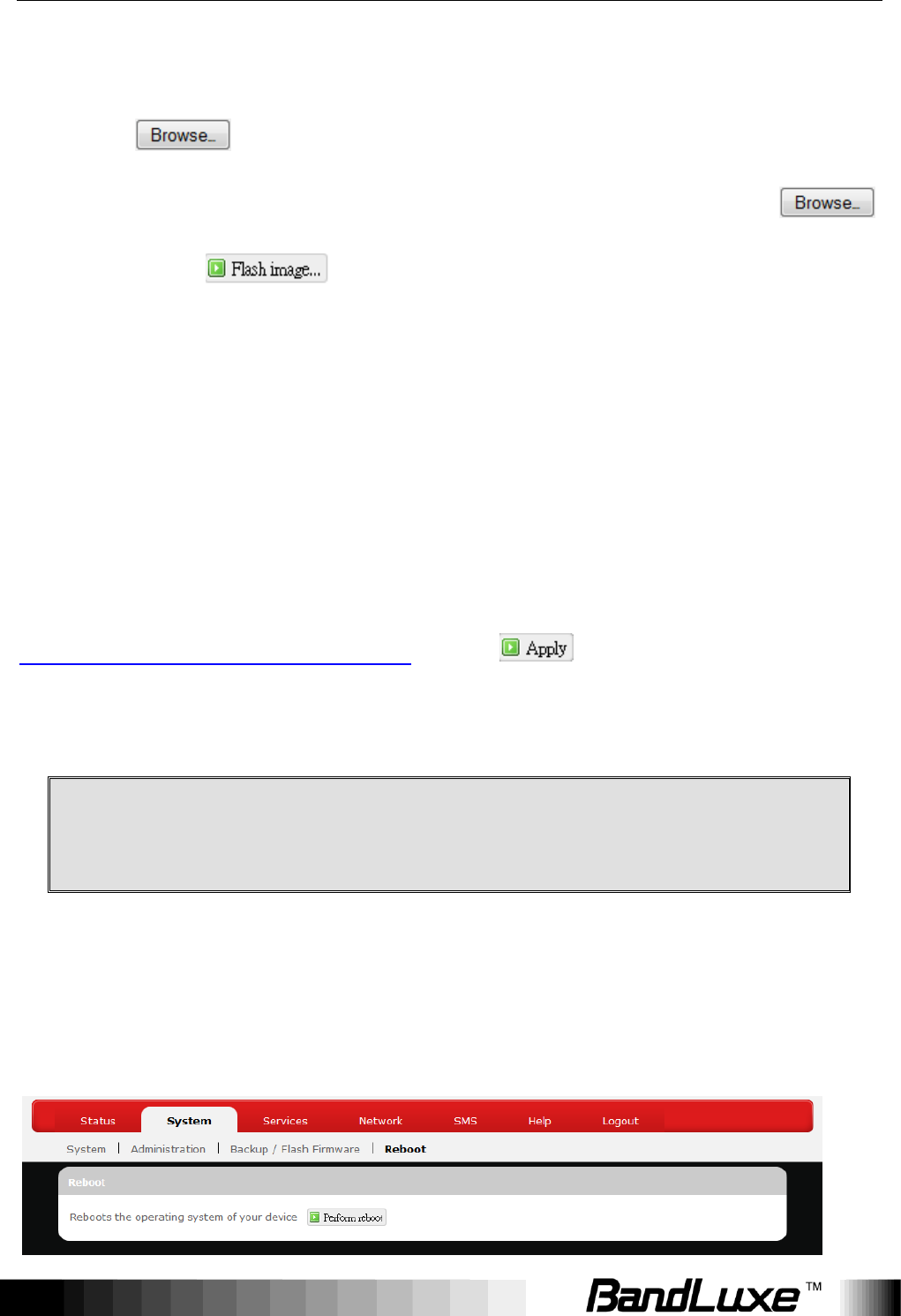
Flash new ipkg package
This option allows you to upgrade this router with the updated IPKG package.
Just click to find and select the IPKG package file, and then click
„Open‟. Confirm that the IPKG package filename appears beside the
button and click . The system will reboot after successful upgrade.
FOTA
This option (Firmware Over The Air) allows you to automatically or manually
upgrade this router‟s firmware wirelessly.
For automatic wireless update, enable “Auto check” and enter the desired time
interval (in hours) between each check of the BandRich website for firmware
update. For manual wireless update, disable “Auto check”. Confirm that the
“Check link for Router” and “Check link for Module” fields have appropriate
web address(es) present in their text boxes, i.e.
http://www.bandrich.com/mdm9x15/ . Click to activate the wireless
update configurations into effect.
To immediately check for firmware upgrade, click Check.
Warning: Upgrading firmware may take a few minutes; do not
turn off the power or press the Reset button during upgrade.
Reboot

Using Web-based Management
24
Click „Perform reboot‟ to restart the router.
Using Web-based Management
25
Services
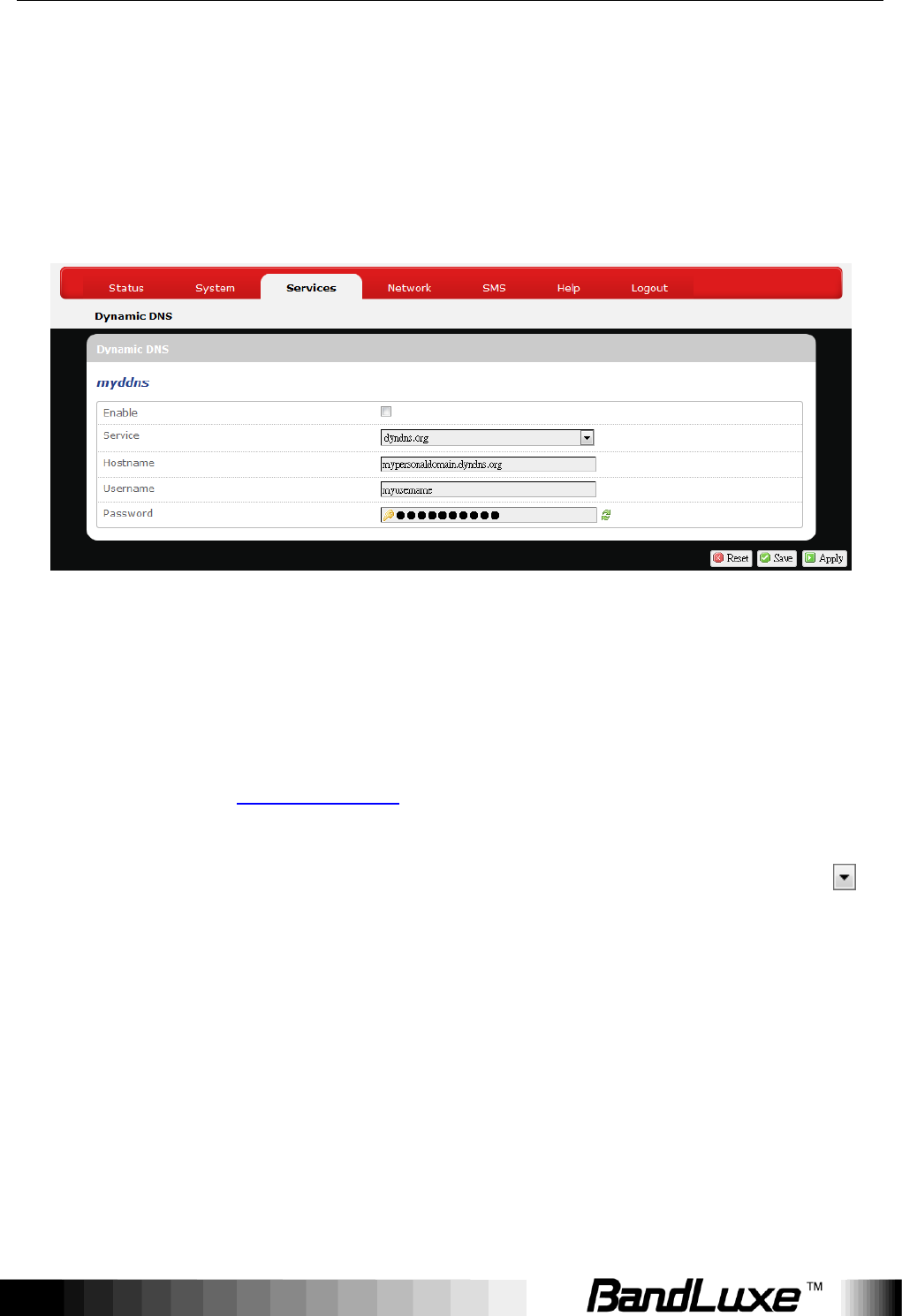
Dynamic DNS
The Services menu hosts configuration options for DDNS (Dynamic Domain
Name Service), which is a system that allows the domain name data held in a
name server to be updated in real time. It allows an Internet domain name to be
assigned to a computer with a varying (dynamic) IP address. Before you can
use this feature, you need to sign up for DDNS with a DDNS provider,
www.dyndns.org or www.TZO.com.
Enable: Check or un-check this box to enable or disable DDNS.
Service: Specifies the DDNS service URL. From the drop-down list, click
and select an URL from the list.
Hostname: Enter the hostname for your DDNS account.
Username: Enter the username for your DDNS account.
Password: Enter the password for your DDNS account.
Using Web-based Management
26
Network
Interfaces
The Interfaces submenu allows interface configurations of different networks
connected to this router. The configuration items are the same for each network
with different default settings.
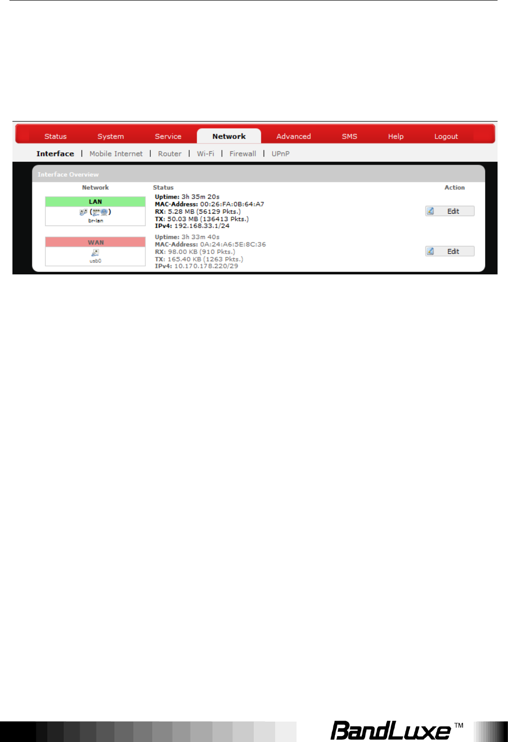
Interface Overview
Here you can see the brief network status summary for LAN (local area
network) and WAN (wide area network). To configure LAN or WAN interfaces,
click the appropriate Edit button and follow the below section Common
Configuration for more details.
Mobile Internet
The Mobile Internet submenu is for setup and adjustment of mobile internet
connection and furthermore has four setting tabs: WWAN Setting, U/SIM PIN
Management, SIM Management, and Preferred Network.
Using Web-based Management
27
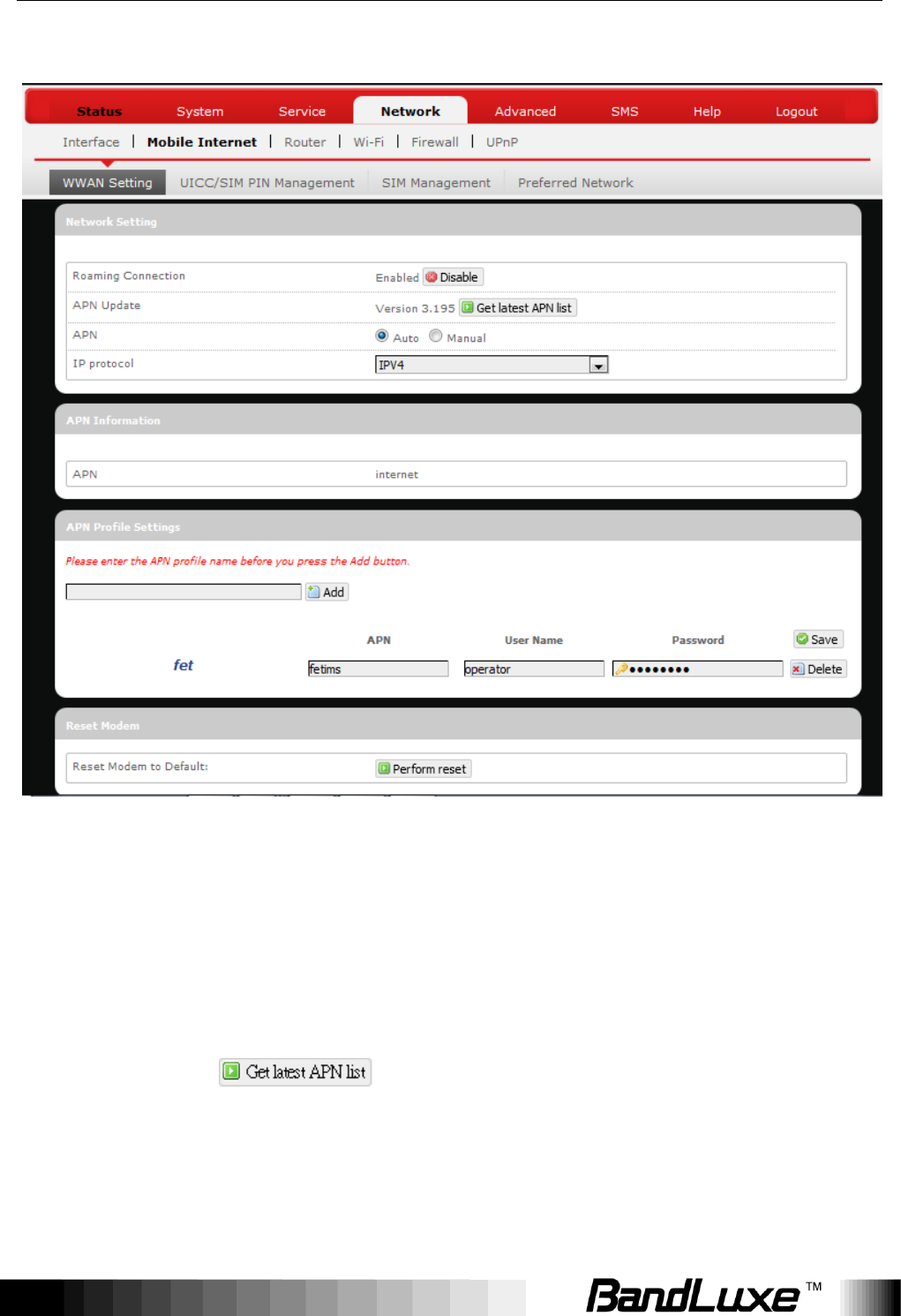
WWAN Setting
Network Settings
Roaming
Connection:
Enables or disables current roaming setting.
APN Update:
Displays the current APN (Access Point Name)
version. To get the latest version of APN, click
.
APN:
„Auto‟ – Uses automatic APN profile settings for
network; this is the default APN setting.
„Manual‟ – Allows the manual choice of APN Profile
Using Web-based Management
28
Settings for network.
Profile
Selection:
This item appears when APN is set to „Manual‟.
Auto APN Information
This section displays automatic APN information.
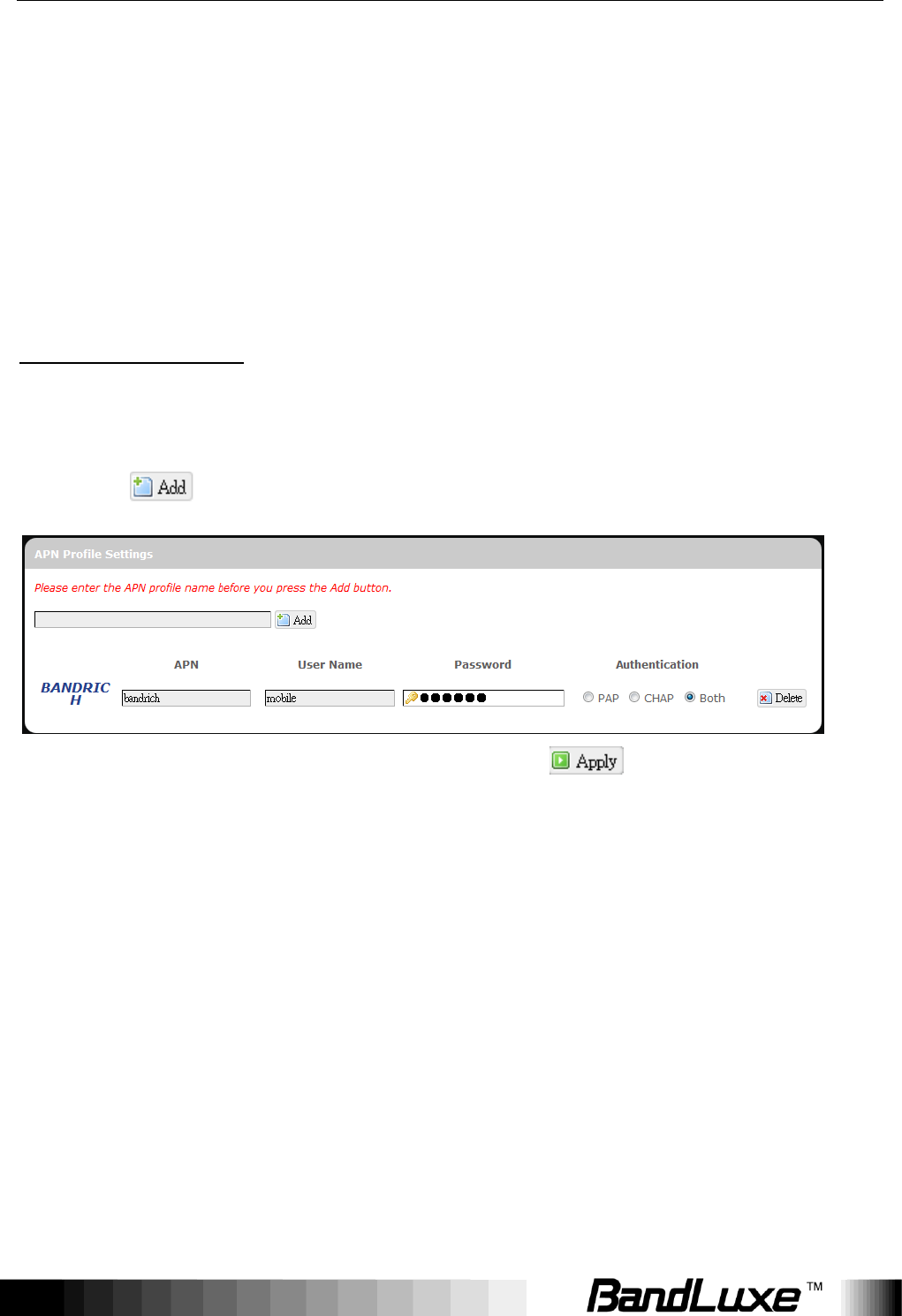
APN Profile Settings
For Advanced Users
This section allows you to establish your own APN profile settings.
To establish a new APN profile, type in a new APN profile name in the text box
and click .
Enter the APN, username, and password. Click .
Reset Modem
Click Perform reset to reset this router to its factory default settings.
Using Web-based Management
29
UICC/SIM PIN Management
This submenu features configurable items that are dependent on the router‟s
mobile internet status, as detailed below.
Scenario 1: No mobile internet service
Without a valid SIM card inserted into the router, the Verify dialog will show the
following SIM card status:
Here the Verify dialog shows SIM status as “Read SIM Fail”, meaning that no
valid SIM card is inserted.
Scenario 2: Mobile internet service pending
If a valid SIM card is inserted into the router requiring PIN code verification, the
Verify dialog will show the following SIM card status:

Using Web-based Management
30
Here the Verify dialog shows the SIM status as “No Verified/Retries:3”,
meaning that a valid SIM card is inserted with PIN code verification pending.
Enter your SIM card verification code in the text box of “PIN Code verify:”, and
then click . Once the PIN code verification is finished, the router is
ready to use the SIM card‟s associated mobile internet access, and the top
right status area will be updated accordingly.
Operator Name:
Displays the name of the internet service provider
WiFi:
Shows the active WiFi SSID of this router
Counter:
Shows number of clients currently connected to the
active SSID
Roaming
Status:
SIM Status
Displays current roaming status
Display SIM card status.
(Carrier) Signal:
Displays strength of the indicated signal type (Carrier)
For example:
1. Without mobile internet connection, the display will
be (no carrier, no signal).
2. If WCDMA (3G) mobile internet connection is
established, the display will be
(WCDMA carrier, excellent signal strength).
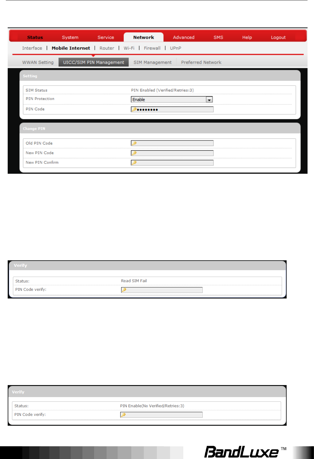
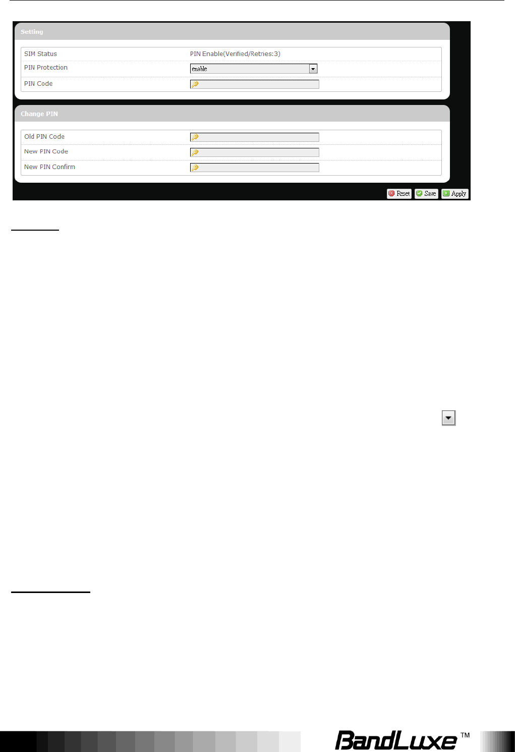
Scenario 3: Mobile internet service enabled
If a valid SIM card is inserted into the router with PIN code verified, the
configuration dialog will be „Setting‟ and/or “Change PIN” to allow further SIM
card management (click after making changes):
Using Web-based Management
31
Setting
SIM Status:
Shows current SIM card status.
“PIN Enable” means that the SIM card is enabled for
mobile internet access.
“PIN Disable(Verified/Retries:#)” means that the SIM
card is enabled for mobile internet access without
requiring PIN code verification. Note that if PIN
protection is re-enabled, # is the number of allowed
PIN verifications remaining before SIM lock occurs.
PIN Protection:
Enables or disables the PIN protection by clicking
and making the appropriate choice from the drop-down
list.
PIN Code
If PIN protection is enabled, you need to enter PIN
code in this text box for making changes in this „Setting‟
dialog.
Change PIN
This option is configurable only if PIN Protection is enabled.
Here you can change the PIN code for enhanced SIM card security.
Old PIN Code:
Enter the old PIN code.
New PIN code:
Enter the new PIN code.
Using Web-based Management
32
New PIN code
confirm:
Enter the same new PIN code again for PIN code
confirmation.
Click after making changes in „Setting‟ and/or “Change PIN”.
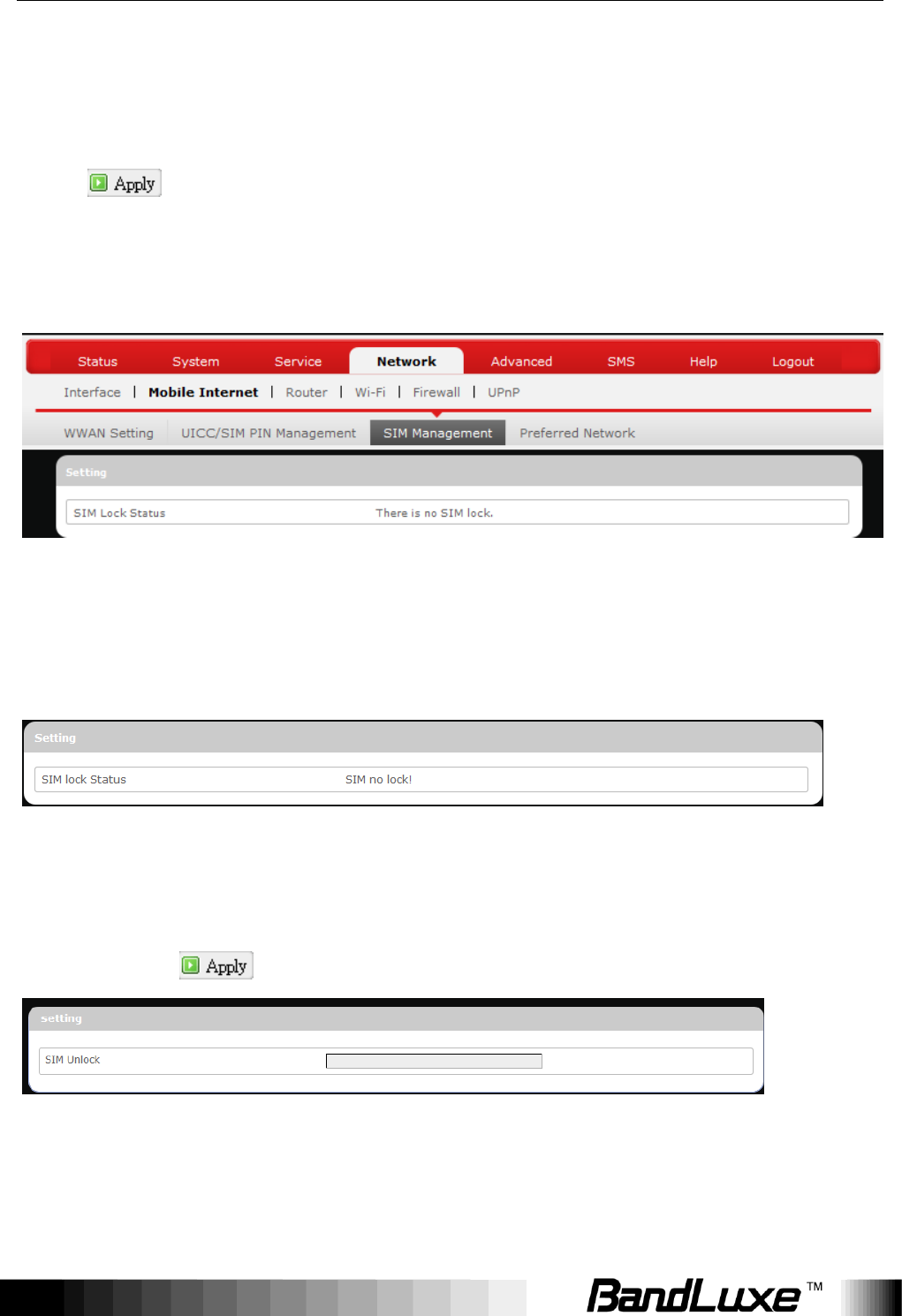
SIM Management
Here you can see the current SIM lock status.
Scenario 1: SIM lock absent
“SIM no lock” means that the SIM card is unlocked.
Scenario 2: SIM lock present
If your SIM card is locked for some reason, here you can also enter the SIM
unlock code to unlock it. After entering the SIM unlock code in the text box “SIM
Unlock”, click .

Using Web-based Management
33
Preferred Network
Here you can select the preferred mobile network type by clicking and
making a choice from the drop-down list. The default choice is Auto. Other
available choice examples are LTE (4G) and WCDMA (3G).
Using Web-based Management
34
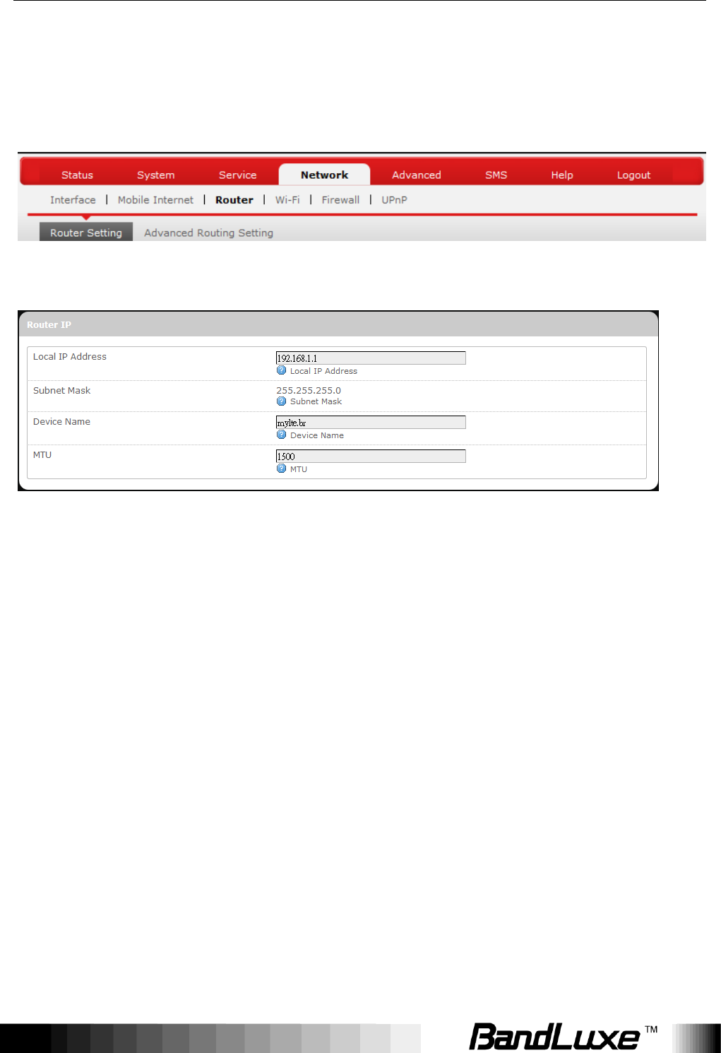
Router
Router Settings
Router IP
Local IP Address:
The default local IP address of this router is
192.168.1.1. If this address conflicts with another
local network device, you can enter another local IP
address here.
Subnet Mask:
Displays current Subnet Mask
Device Name:
The current device name is displayed in gray color.
The device name can be changed by typing in the
new device name in this text box.
MTU:
The current MTU (maximum transmission unit with
default value of 1500 bytes) is displayed in gray color.
The MTU can be changed by typing in the new MTU
value in this text box.
Using Web-based Management
35
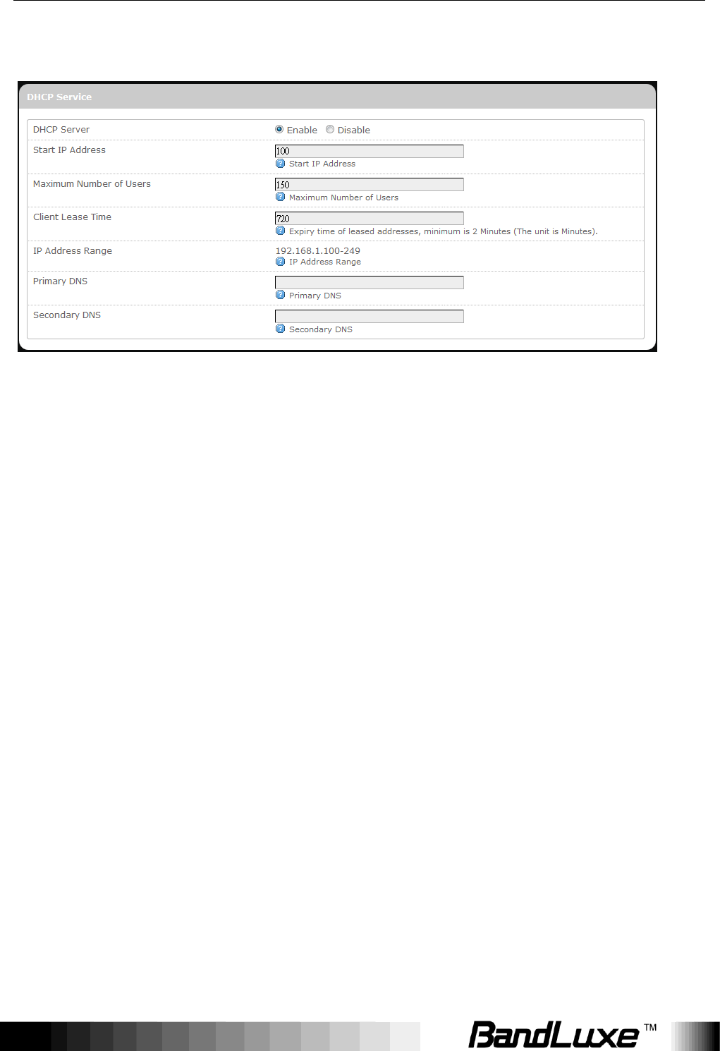
DHCP Service
DHCP Server:
Enables or disables the DHCP Server feature.
Start IP Address:
Specifies the starting number of the last 3 digits of
assigned client IP address. For example, the default
value of 100 means that the first assigned client IP
address will be 192.168.1.100; the next assigned
client IP address will be 192.168.1.101; and so on…
Maximum
Number of Users:
Specifies maximum number of users for this router.
The default setting is 150 users.
Client Lease
Time:
Specifies the amount of lease time allocated to clients
of this router, i.e. the expiry time of leased addresses.
Use „h‟ to indicate hours or use „m‟ to indicate
minutes.
IP Address
Range:
Displays assignable local IP address range of this
router
Primary DNS:
If needed, specify the primary Domain Name System
here.
Secondary DNS:
If needed, specify the secondary Domain Name
System here.
Using Web-based Management
36
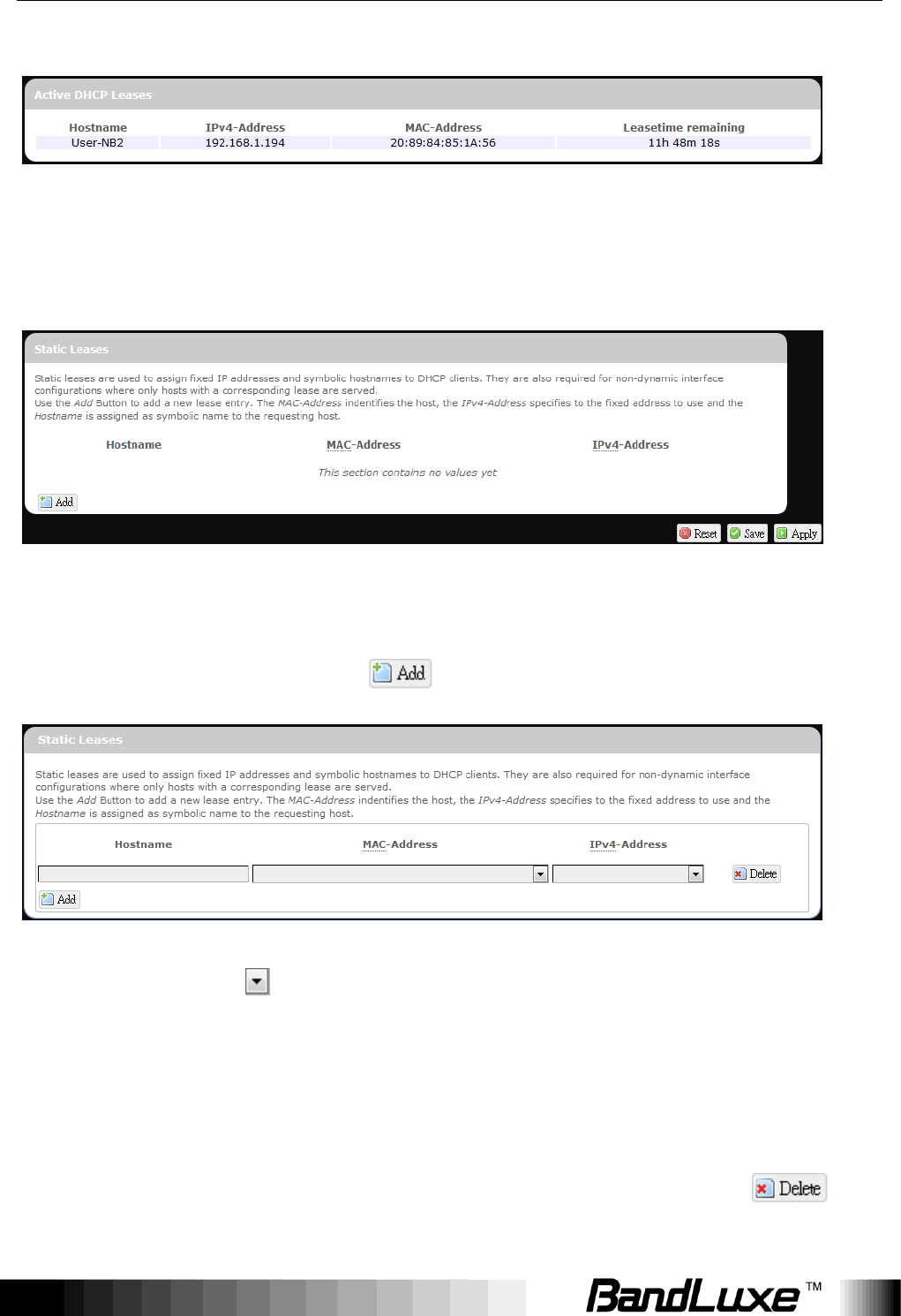
Active DHCP Leases
This section displays active DHCP lease information for each client: Hostname,
IPv4 address, MAC address, and Lease time remaining.
Static Leases
This option allows fixed IP address and symbolic hostname assignments for
DHCP clients.
To add a static lease, first click .
Enter the desired hostname. Choose the desired MAC address and
IPv4-Address (click and select a rule from the drop-down list; if
“--Custom--" is selected, the drop-down list will change to a text box to allow
you to enter your custom address).
The MAC address is for host identification, whereas the IPv4 address specifies
the fixed address for static lease.
To remove any unwanted static lease, just click the corresponding
button.
Using Web-based Management
37
Click after making any changes.
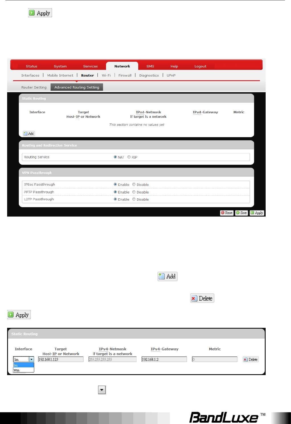
Advanced Routing settings
Static Routing
This option allows fixed network routing path assignment (as opposed to the
initial adaptive routing).
To add a static network routing path, click . To remove any unwanted
static network routing path, click the corresponding button. Click
after making any changes.
Interface:
Click and choose „lan‟ (local area network) or

Using Web-based Management
38
„wan‟ (wide area network).
Target:
Enter the target host IP or network address here.
IPv4-Netmask:
Displays the IPv4-Netmask address (the default is
255.255.255.255). A custom IPv4-Netmask can also
be specified here.
IPv4-Gateway:
If needed, a custom IPv4-Gateway address can be
specified here.
Metric:
Specifies the network path priority number (usually
associated with the network path‟s administrative
distance). The lower the metric number, the higher
priority of this static route in the network routing
protocol.
The default value is 0 (highest priority). A different
metric number can also be specified here.
Note:
If contents in the text box is invalid, a will appear on the right
side of the text box, and the text color changes to red. For example,
the following demonstrates an invalid target Host-IP or Network
address:
Routing and Redirection Service
This option enables or disables Network Address Translation (NAT) service,
which is a standard that allows multiple computers on a private network to
share a single IP address.
VPN Passthrough
A Virtual Private Network (VPN) is a type of secured private network
connection, built upon publicly-accessible infrastructure such as the Internet.
They usually provide connectivity to various devices behind a gateway or
firewall.
Using Web-based Management
39
IPSec
Passthrough:
IP Security (IPSec) provides authentication and
encryption. Since it is mainly a Layer 3 technology, it
can secure all data on the network. To allow IPSec
tunnels to pass through the Router, click „Enabled‟.
PPTP
Passthrough:
Point-to-Point Tunneling Protocol (PPTP) allows you
to establish a connection to an enterprise network. To
allow PPTP tunnels to pass through the Router, click
Enabled.
L2TP
Passthrough:
Layer 2 Tunneling Protocol (L2TP) is an extension of
the Point-to-Point Tunneling Protocol and is also used
to establish virtual private networks. To allow L2TP
tunnels to pass through the Router, click Enabled.
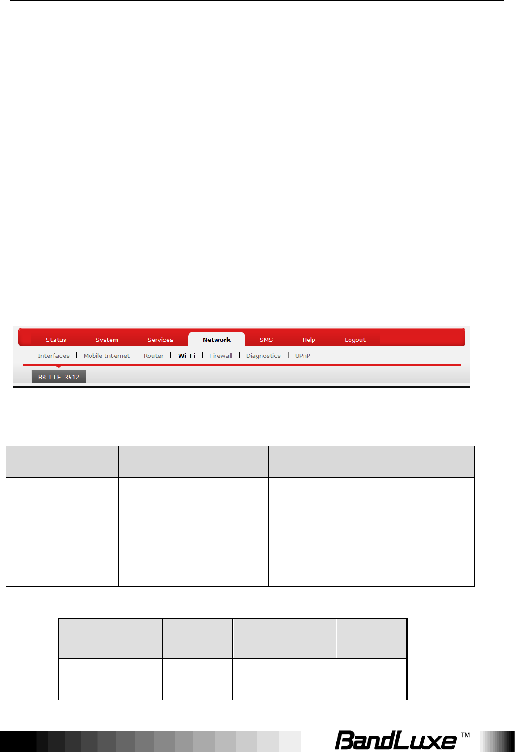
WiFi
This submenu item is for configuring all Wi-Fi-related settings. This router
supports up to two WiFi SSIDs. The default SSID is as follows:
Tab Name
Corresponding SSID
Default Password
“BR_LTE_xxxx”
BR_LTE_xxxx
The last 4 digits of MAC
address (xxxx) converted into
2-digit decimal numbers,
please see table below for
conversion method.
Hexadecimal
Digit
Decimal
Number
Hexadecimal
Digit
Decimal
Number
0
00
8
08
1
01
9
09
Using Web-based Management
40
2
02
A
10
3
03
B
11
4
04
C
12
5
05
D
13
6
06
E
14
7
07
F
15
SSID and Password Example:
MAC Address
Corresponding SSID
Default Password
0026FA0B314A
BR_LTE_314A
03010410
Each tab has identical sets of configuration categories:
Device Configuration and Interface Configuration.
Please click after making any changes in this submenu.
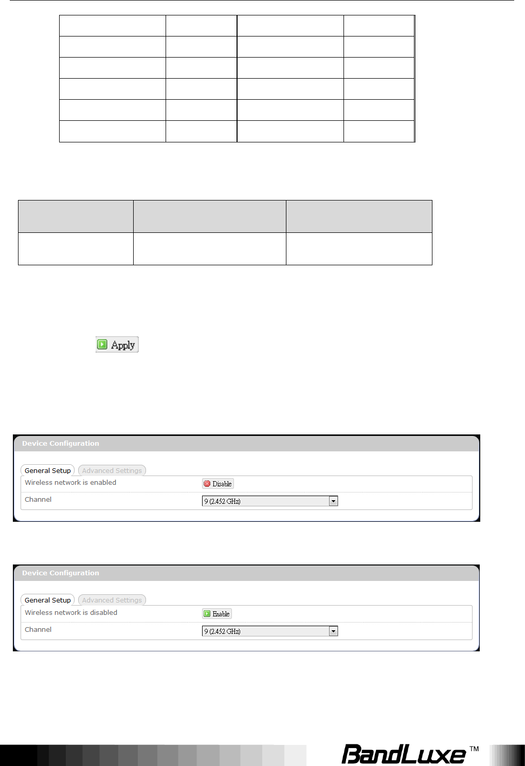
Device Configuration
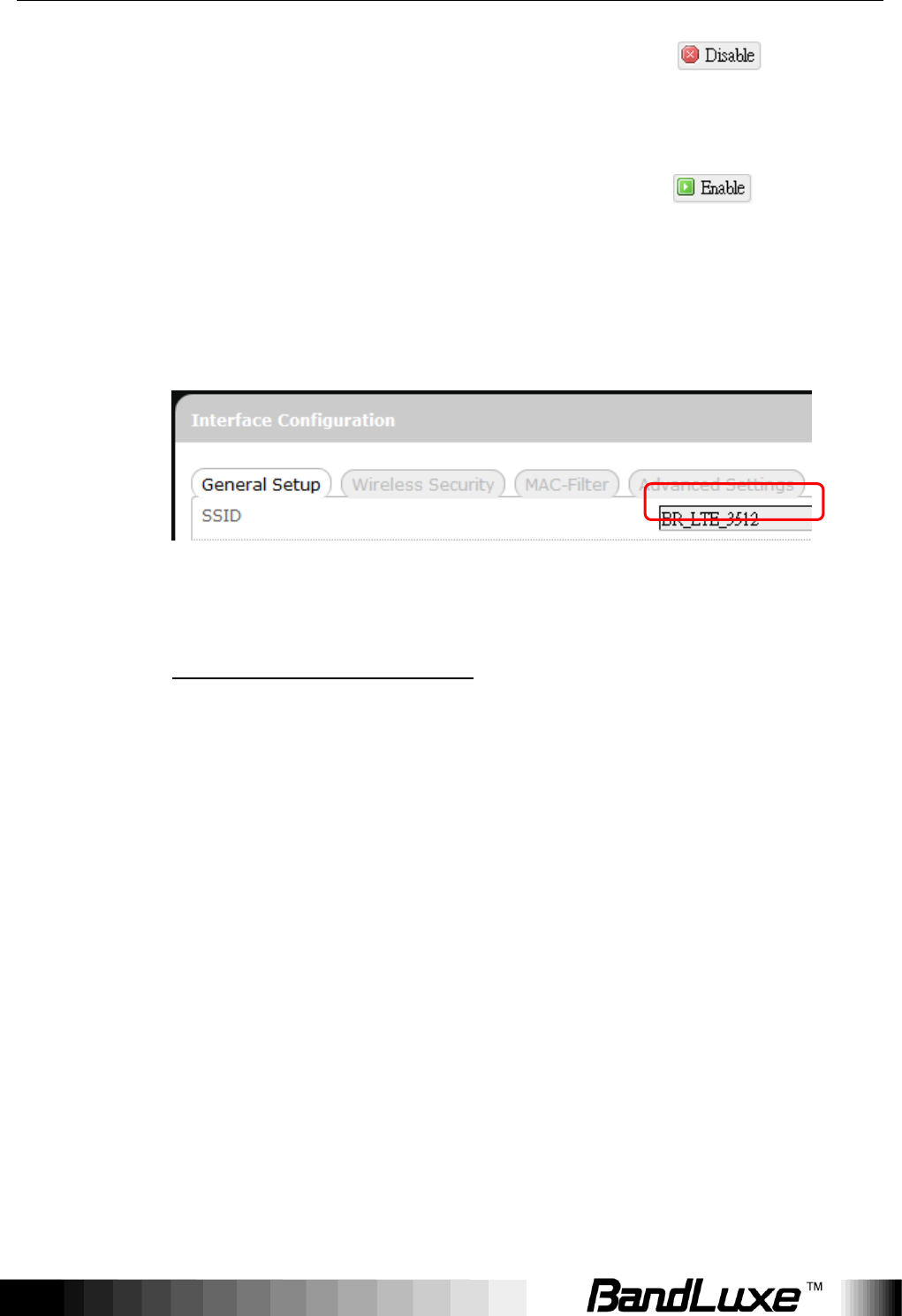
General Setup
or
Wireless
network is
WiFi connection of the associated SSID is enabled.
Using Web-based Management
41
enabled*
To disable WiFi connection of this SSID, click .
Wireless
network is
disabled*
WiFi connection of the associated SSID is disabled.
To enable WiFi connection of this SSID, click .
* Note: The associated SSID is displayed either in the
selected submenu tab under WiFi or in the WiFi category
item Interface Configuration General Setup SSID.
Channel:
Selects the WiFi channel for communication. The available
choices are:
Channel (carrier frequency)
1 (2.412 GHz)
2 (2.417 GHz)
3 (2.422 GHz)
4 (2.427 GHz)
5 (2.432 GHz)
6 (2.437 GHz)
7 (2.442 GHz)
8 (2.447 GHz)
9 (2.452 GHz)
10 (2.457 GHz)
11 (2.462 GHz)
auto
-- custom --
assigns channel automatically
manually specifies WiFi channel
Normally one of the channels is already selected, and no
change is needed unless there exists interference problems
with other WiFi or Bluetooth devices (that also use the
Using Web-based Management
42
2.4GHz frequency range for communications).
Alternatively, you can select „auto‟ to let the system select
the channel automatically, or you can select
“-- custom --” and enter your own channel specification in
the text box.
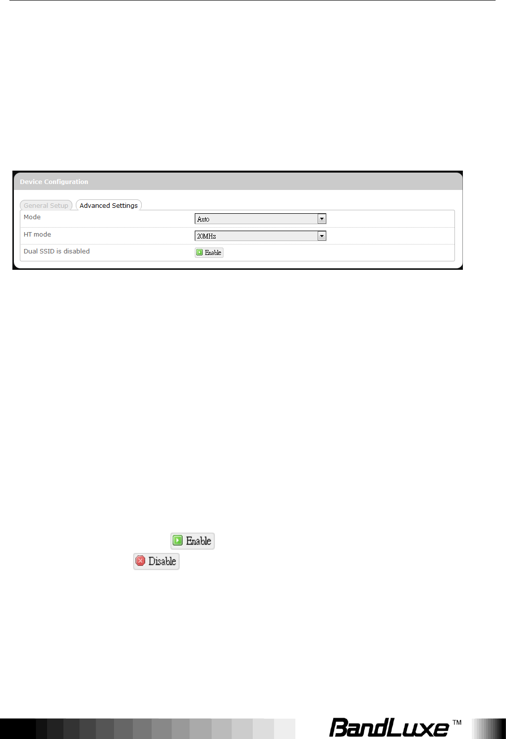
Advanced Settings
Mode
Specifies the IEEE wireless standard for WiFi
communication. The choices are:
Auto:
(Default choice) The router
automatically chooses the
optimal IEEE wireless
standard.
802.11b:
Data speed up to 11 Mbps
802.11g:
Data speed up to 54 Mbps
802.11n:
Data speed up to 300 Mbps
HT mode
Specifies channel width for data communications.
The choices are:
20MHz:
Single 20MHz channel
20MHz / 40MHz
Single or dual 20MHz
channels
Dual SSID is
disabled/enabled
Click to activate the second SSID, or click
to deactivate the second SSID.
Using Web-based Management
43
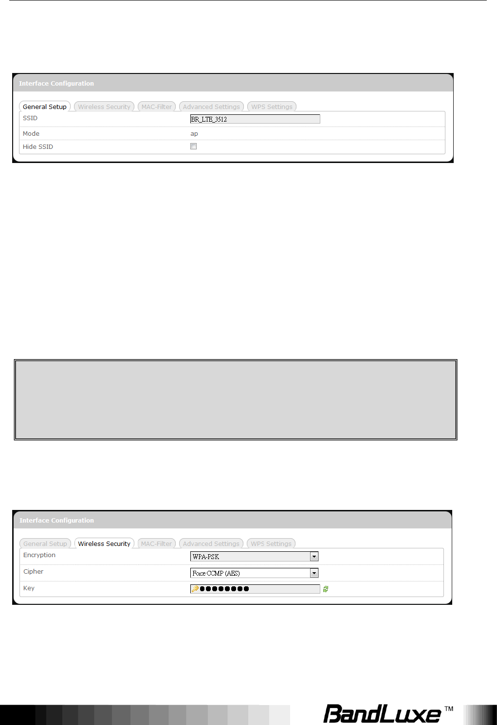
Interface Configuration
General Setup
SSID
Service Set Identification
To change the SSID, click the text box and enter the
new SSID (up to 32 alphanumeric characters)
Mode
Wireless operating mode of this router.
AP:
Wireless Access Point
Hide SSID
Enable this option to make wireless network of this
SSID unavailable to nearby WiFi clients.
Disable this option to make wireless network of this
SSID available to nearby WiFi clients (default setting).
Wireless Security
This router supports wireless data encryption, a must for wireless data security.
The Wireless Security Interface Configuration items will change according to
the chosen encryption method.
CAUTION: To enable “Hide SSID”, we strongly advise you to do so via
wired LAN connection, since wireless LAN connection with this SSID will
be lost with this option applied! If both SSIDs are hidden, then the
communications with this router must be done via a LAN port, or this
router must be reset to factory default settings.
Using Web-based Management
44
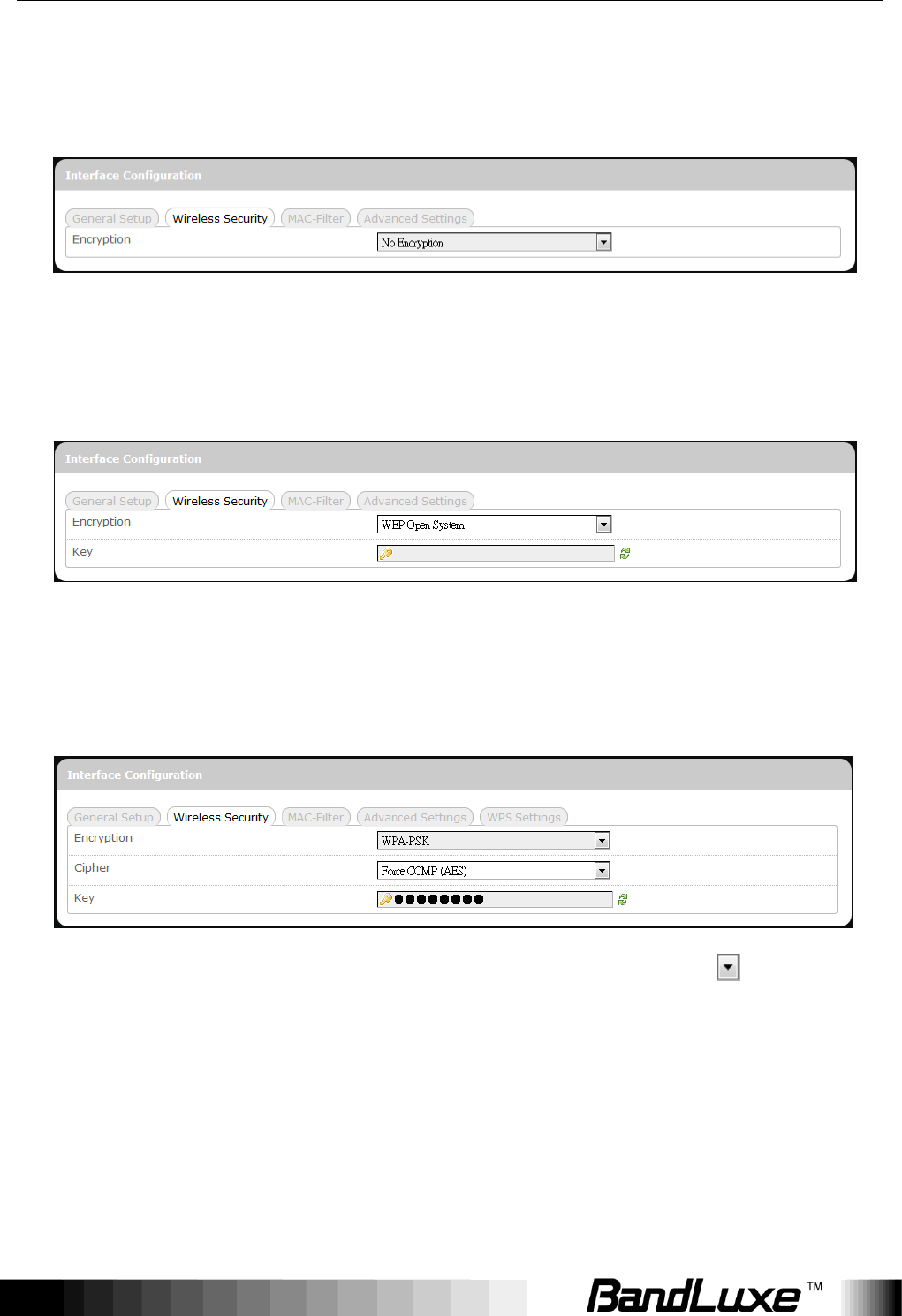
The encryption options are:
1. No Encryption
Data transmitted over wireless networks can be seen by others.
2. WEP Open System
Wired Equivalent Privacy encryption with Open System authentication
Key: Enter a password for accessing this SSID‟s wireless network.
3. WPA-PSK
“WiFi Protected Access – Pre-Shared Key” encryption
Cipher: Specify the desired encryption protocol by clicking and
selecting an option from the drop-down list:
auto – (default setting) the system automatically chooses the
optimal encryption protocol
Force CCMP (AES) – Use CCMP (AES) encryption exclusively
(stronger than TKIP)
Force TKIP – Use TKIP encryption exclusively
Using Web-based Management
45
Force TKIP and CCMP (AES) – Use TKIP and CCMP (AES)
encryption protocols together
Key: Enter a password for accessing this SSID‟s wireless network.
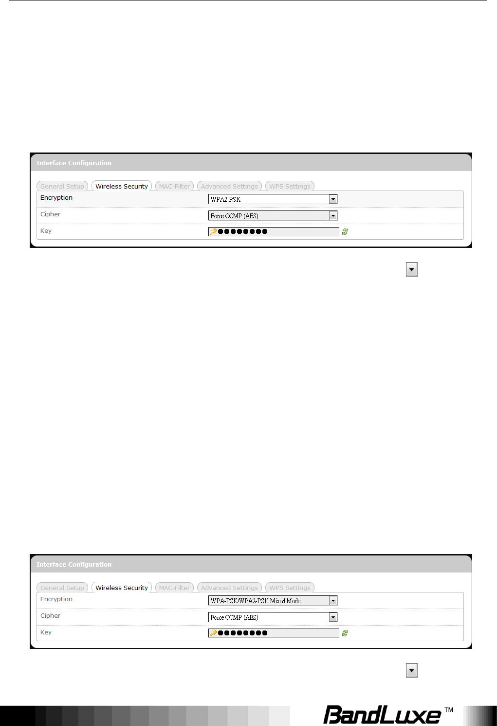
4. WPA2-PSK
“WiFi Protected Access II – Pre-Shared Key” encryption
Cipher: Specifies the desired encryption protocol by clicking and
selecting an option from the drop-down list:
auto – (Default setting) the system automatically chooses the
optimal encryption protocol
Force CCMP (AES) – Use CCMP (AES) encryption exclusively
(stronger than TKIP)
Force TKIP – Use TKIP encryption exclusively
Force TKIP and CCMP (AES) – Use TKIP and CCMP (AES)
encryption protocols together
Key: Enter a password for accessing this SSID‟s wireless network.
5. WPA-PSK/WPA2-PSK Mixed Mode
“WiFi Protected Access I + II – Pre-Shared Key” encryption
Cipher: Specifies the desired encryption protocol by clicking and
Using Web-based Management
46
selecting an option from the drop-down list:
auto – (Default setting) the system automatically chooses the
optimal encryption protocol
Force CCMP (AES) – Use CCMP (AES) encryption exclusively
(stronger than TKIP)
Force TKIP – Use TKIP encryption exclusively
Force TKIP and CCMP (AES) – Use TKIP and CCMP (AES)
encryption protocols together
Key: Enter a password for accessing this SSID‟s wireless network.
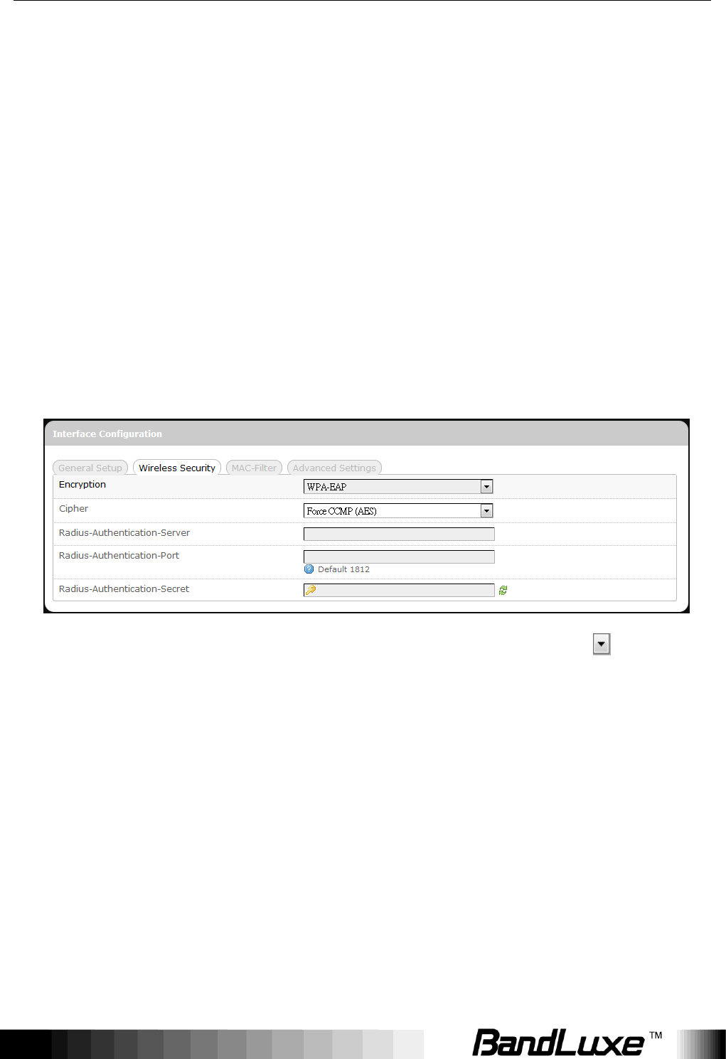
6. WPA-EAP
“WiFi Protected Access – Extensible Authentication Protocol” encryption
Cipher: Specifies the desired encryption protocol by clicking and
selecting an option from the drop-down list:
auto – (default setting) the system automatically chooses the
optimal encryption protocol
Force CCMP (AES) – Use CCMP (AES) encryption exclusively
(stronger than TKIP)
Force TKIP – Use TKIP encryption exclusively
Force TKIP and CCMP (AES) – Use TKIP and CCMP (AES)
encryption protocols together
Radius-Authentication-Server: Enter the name of the RADIUS
authentication server.
Radius-Authentication-Port: Enter the port number of the RADIUS
Using Web-based Management
47
authentication port (the default port number is 1812).
Radius-Authentication-Secret: Enter the desired RADIUS secret
password.
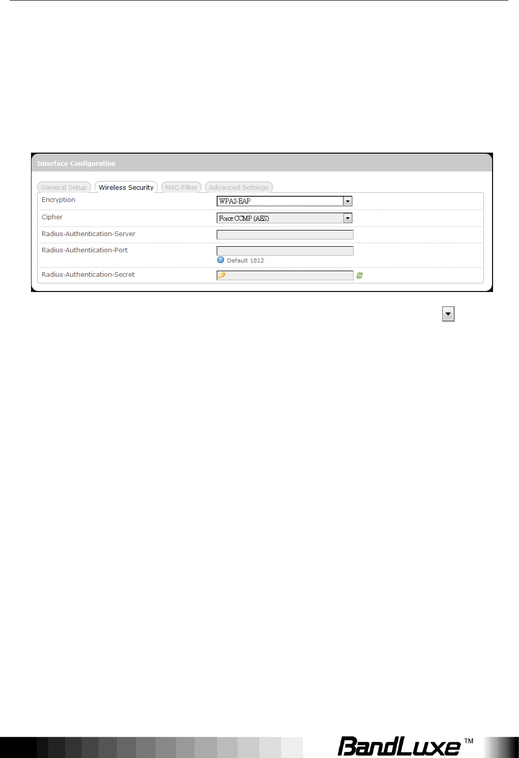
7. WPA2-EAP
“WiFi Protected Access II – Extensible Authentication Protocol” encryption
Cipher: Specifies the desired encryption protocol by clicking and
selecting an option from the drop-down list:
auto – (default setting) the system automatically chooses the
optimal encryption protocol
Force CCMP (AES) – Use CCMP (AES) encryption exclusively
(stronger than TKIP)
Force TKIP – Use TKIP encryption exclusively
Force TKIP and CCMP (AES) – Use TKIP and CCMP (AES)
encryption protocols together
Radius-Authentication-Server: Enter the name of the RADIUS
authentication server.
Radius-Authentication-Port: Enter the port number of the RADIUS
authentication port (the default port number is 1812).
Radius-Authentication-Secret: Enter the desired RADIUS secret
password.
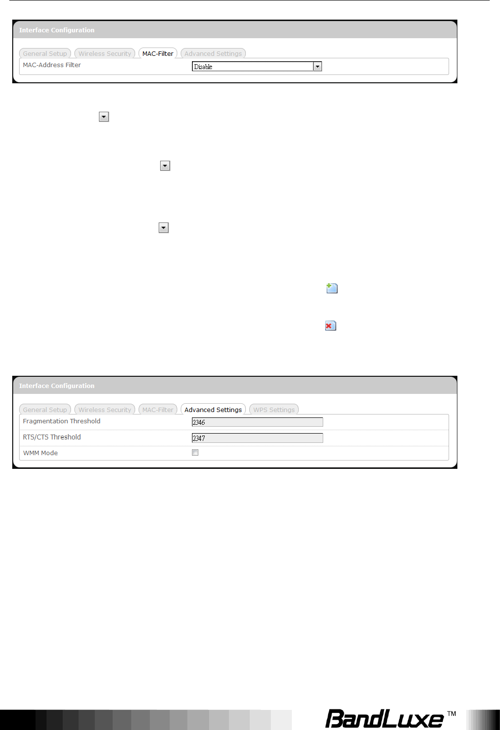
MAC-Filter
MAC-Address Filter:
Using Web-based Management
48
This tab item allows you to selectively allow or block clients from network
access. Click and select an option from the drop-down list:
1. Disable – The MAC address filter is disabled (default option).
2. White list* – Click and select a desired MAC address from the
drop-down list, or select “-- custom --" and enter a specific client‟s MAC
address.
3. Black list* – Click and select an undesired MAC address from the
drop-down list, or select “-- custom --" and enter a specific client‟s MAC
address.
* To add another MAC address to the list, click to add a new
drop-down list; then repeat the MAC address selection/specification.
To remove a MAC address from the list, click .
Advanced Settings
This tab item is for advanced adjustment settings for WiFi connection.
Fragmentation
Threshold
Maximum transmittable data packet frame size
without frame fragmentation; the default value is 2346
RTS/CTS
Threshold
Defines Request-To-Send (transmitter) and
Clear-To-Send (receiver) control packet size; the
default value is 2347
WMM Mode
Enables or disables Wi-Fi Multimedia Mode, which
gives multimedia data contents (voice, video, and
audio) higher priority over wireless networks. The
Using Web-based Management
49
default setting of WMM Mode is Disabled.
WPS Settings
WiFi Protected Setup Settings
This tab item appears when „Encryption‟ in “Wireless Security” is set to one of
the following: WPA-PSK, WPA2-PSK, or WPA-PSK/WPA2-PSK Mixed Mode.
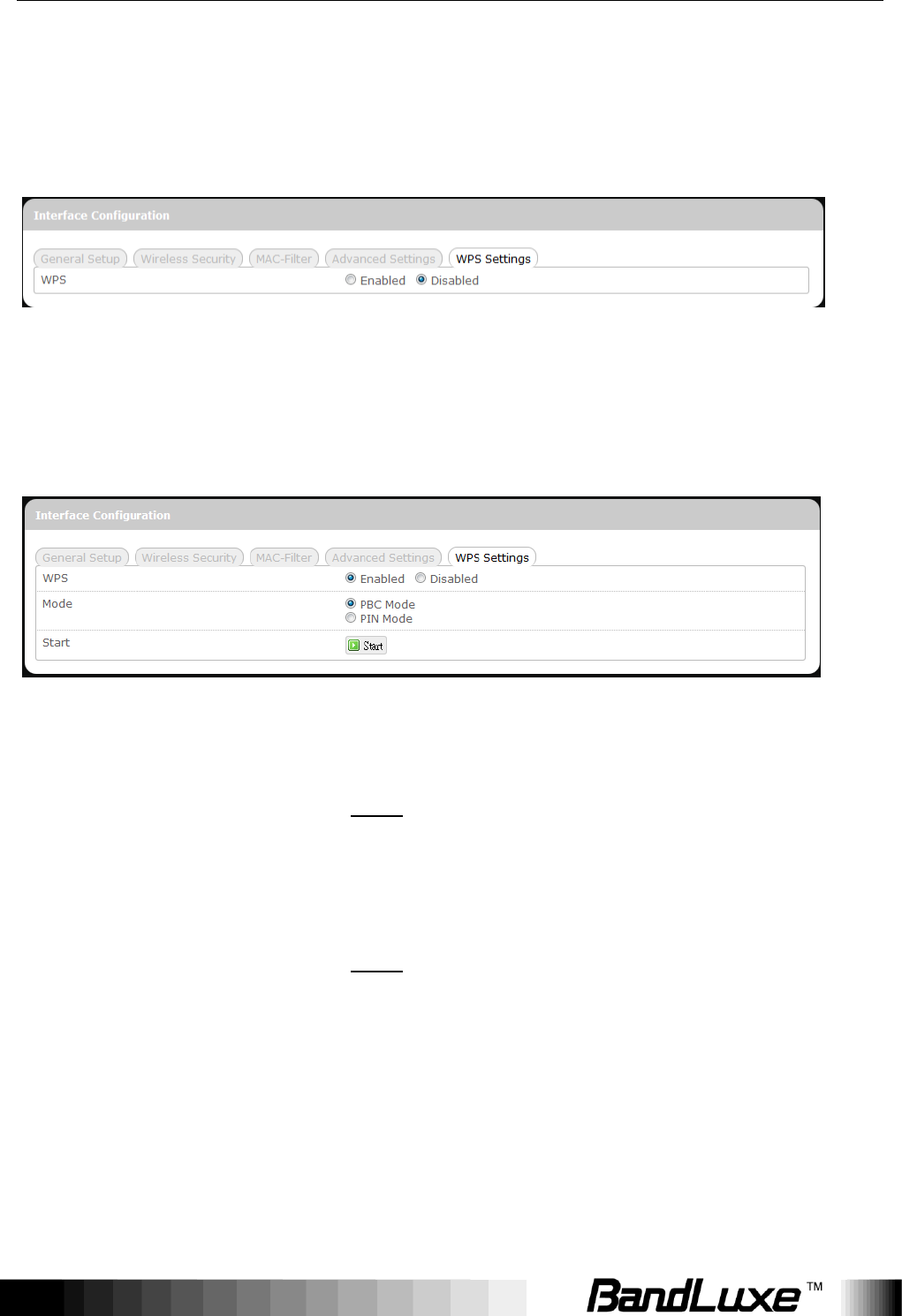
WPS: To enable the WPS button for quick WiFi connection setup, click
„Enabled‟, and 2 additional items will appear: Mode and Start.
Mode:
Specifies WPS setup mode
PBC Mode –
Push Button Configuration Mode
(Note: To use this setup method, the client
must have a WPS button configured to PBC
Mode.)
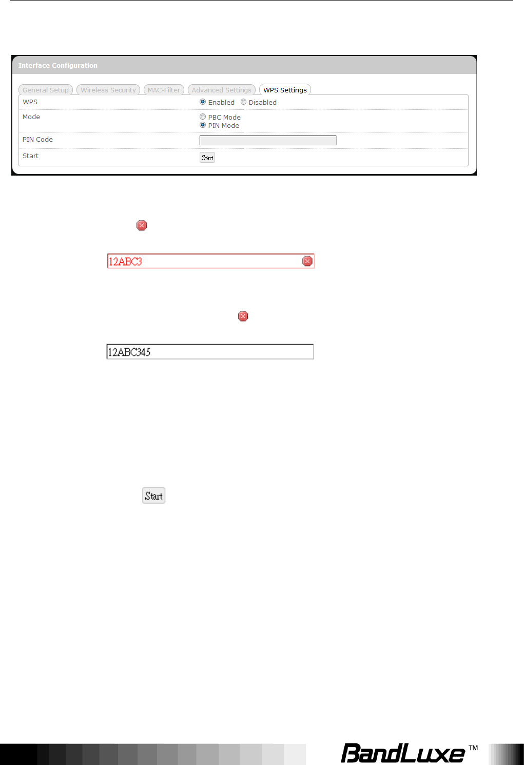
PIN Mode –
Personal Identification Number Mode
(Note: To use this setup method, the client
must have a WPS button configured to PIN
Mode.)
After choosing PIN Mode, an additional text
box item “PIN Code” will appear.
PIN Code:
This text box item appears when „Mode‟ is set to “PIN
Mode”.
Enter the 8-digit alphanumeric PIN in the text box. This PIN
Using Web-based Management
50
must match the PIN of the router client.
If the PIN entered is invalid, the text color will become red
with on the right.
Whenever the PIN entered becomes valid, the text color
will be black without on the right.
Start:
After setting up WPS Mode (PBC or PIN), click the router
client‟s corresponding hardware/software WPS button
(actual router client hardware/software WPS button
behavior will depend on router client manufacturer‟s
design).
Click or press-and-hold the router‟s physical
SS/WPS/Reset button for just over 3 seconds to start the
WPS process.
Using Web-based Management
51
Firewall
Single Port Forward
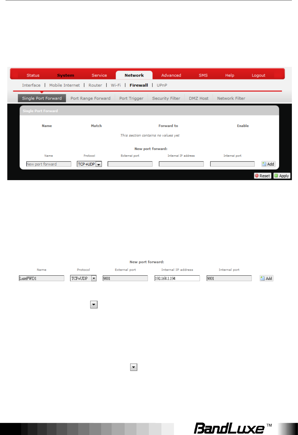
Single Port Forward
Port Forwarding allows you to set up public services on your network, such as
web servers, ftp servers, e-mail servers, and other specialized Internet
applications.
To forward a single port:
1. Name: Enter an application name for this port forwarding rule.
2. Protocol: Click and select a protocol from the drop down list –
TCP+UDP (default), TCP, UDP, or Other…
3. External port: Enter the port number of the external port used by the
server or Internet application. Afterward, this port number will be echoed
to the text box of “Internal port”.
4. Internal IP address: Click and select an IP address from drop-down
list, or select “--custom--" and enter IP address in text box.
5. Internal port: This text box will automatically receive port number
entered in the text box of “External port”, or you can enter your own port
Using Web-based Management
52
number in the same text box.
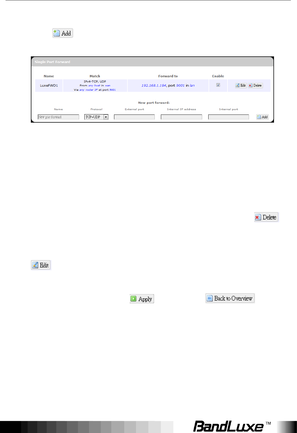
6. Click . The port forwarding rule you have just entered will be
added to the Port Forwards list.
In the status area, the message Unapplied Change may appear next to
“Operator Name” to indicate configuration changes temporarily stored in
the router.
7. More rules can be added to the Port Forwards list by repeating Steps
1-6.
8. (a)To enable or disable a Port Forwards list rule, click its check box
under „Enable‟.
(b) To remove any Port Forwards rule, click its corresponding
button.
9. To edit a particular Port Forwards rule in detail, click its corresponding
button, and the rule‟s associated configuration page (much more
flexible and detailed than express settings in Steps 1-5) will appear. After
making any changes, click . Finally click to exit
this configuration page.
(a) (b)
Using Web-based Management
53
Note:
Numerical and text values shown in the illustrative examples are for
demonstration purposes only and are not for actual operation.
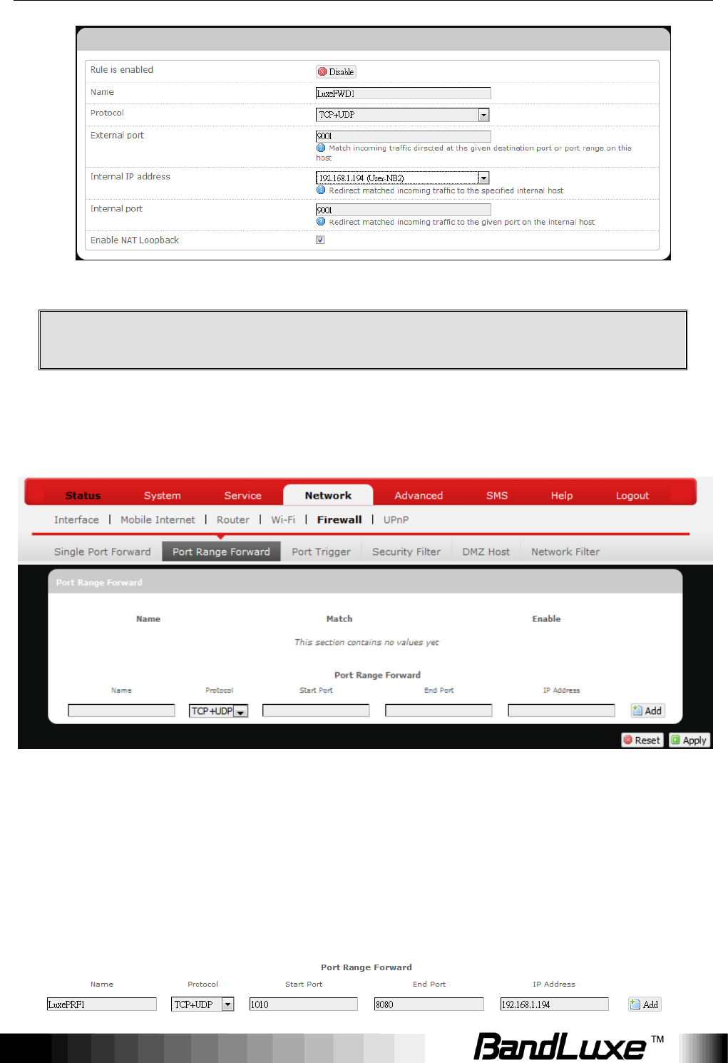
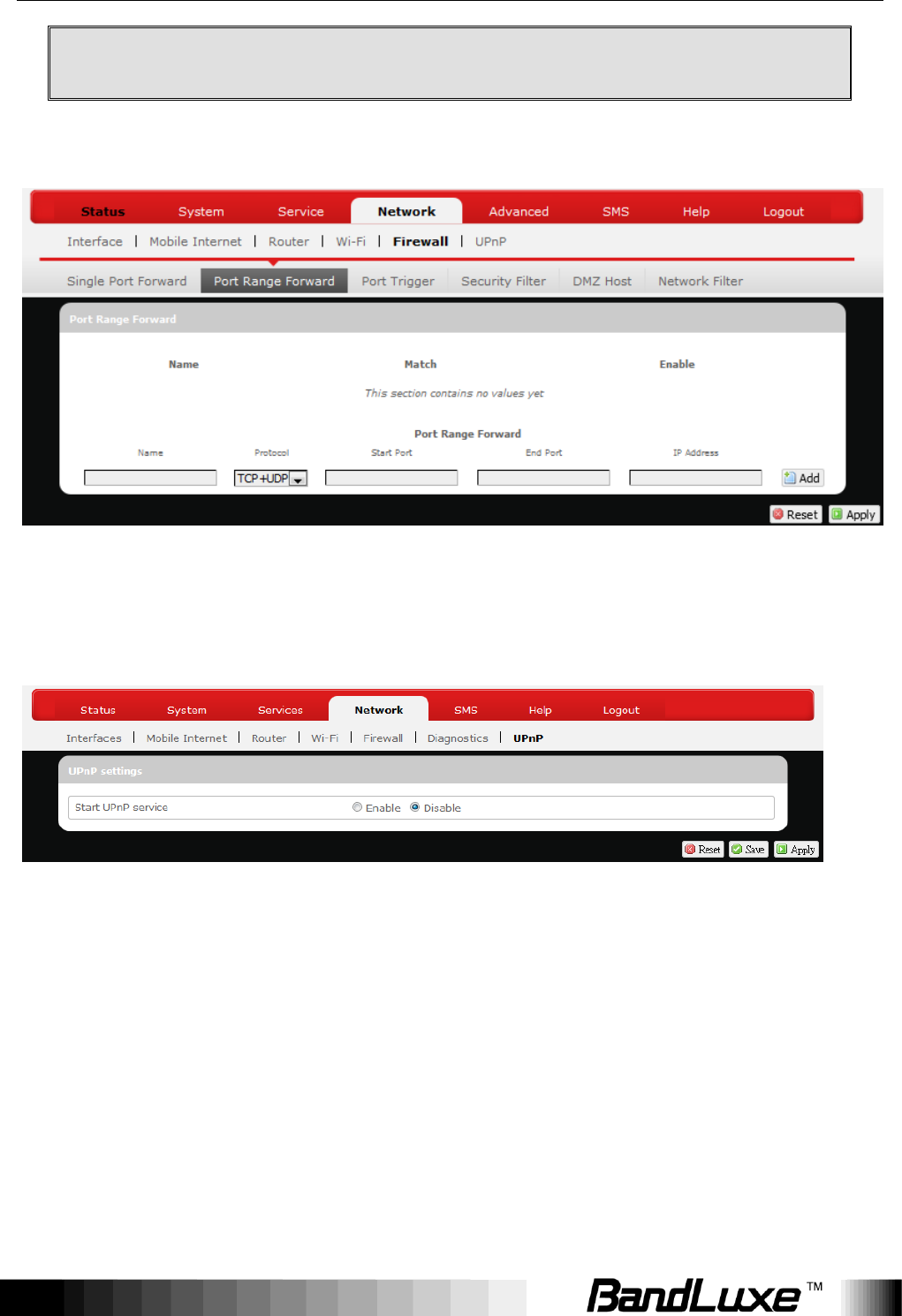
Port Range Forward
Port Range Forward
Port Range Forward allows you to set up public services on your network, such
as web servers, ftp servers, e-mail servers, and other specialized Internet
applications.
To forward a port range:
Using Web-based Management
54
1. Name: Enter an application name for this port range forwarding rule.
2. Protocol: Click and select a protocol from the drop down list –
TCP+UDP (default), TCP, UDP, or Other…
3. Port Range Forward: Specify the range of port forwarding by entering
the Start Port number and the End Port number.
4. IP address: Enter the IP address of the PC running the specific
application.
5. Click . The port range forwarding rule you have just entered will be
added to the Port Range Forward list.
In
the status area, the message Unapplied Change may appear next to
“Operator Name” to indicate configuration changes temporarily stored in
the router.
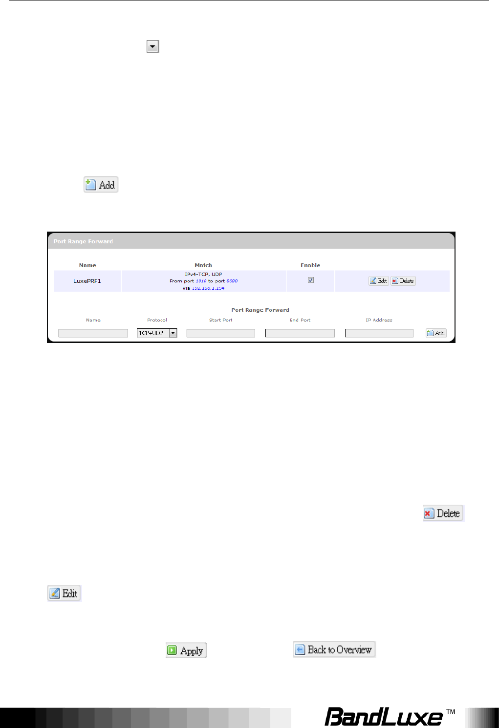
6. More rules can be added to the Port Range Forward list by repeating
Steps 0-0.
7. (a) To enable or disable a Port Forwards list rule, click its check box
under „Enable‟.
(b) To remove any Port Forwards rule, click its corresponding
button.
8. To edit a particular Port Forwards rule in detail, click its corresponding
button, and the rule‟s associated configuration page (more flexible
and detailed than express settings in Steps 0-0) will appear. After making
any changes, click . Finally click to exit this
configuration page.
(a) (b)
Using Web-based Management
55
Note:
Numerical and text values shown in the illustrative examples are for
demonstration purposes only and are not for actual operation.
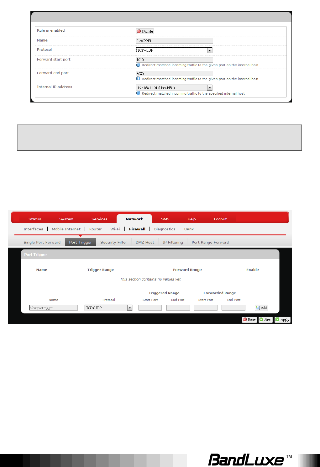
Port Trigger
Port Trigger
Port Triggering allows the Router to watch outgoing data for specific port
numbers. The Router remembers the IP address of the computer that sends
the matching data, so that when the requested data returns through the Router,
the data is pulled back to the proper computer by way of IP address and port
mapping rules.
To add a new Port Triggering rule:
Using Web-based Management
56
1. Name: enter an application name for this port triggering rule.
2. Protocol: click and select a protocol from the drop down list –
TCP+UDP (default), TCP, UDP, or Other…
3. Triggered Range: enter the Start Port and End Port for the triggered
port number range of the Internet application (please check its
documentation for the port number(s) needed).
4. Forwarded Range: enter the Start Port and End Port for the forwarded
port number range of the Internet application (please check its
documentation for the port number(s) needed).
5. Click . The port triggering rule you have just entered will be added
to the Port Triggering list.
In
the status area, the message Unapplied Change may appear next to
“Operator Name” to indicate configuration changes stored in the router.
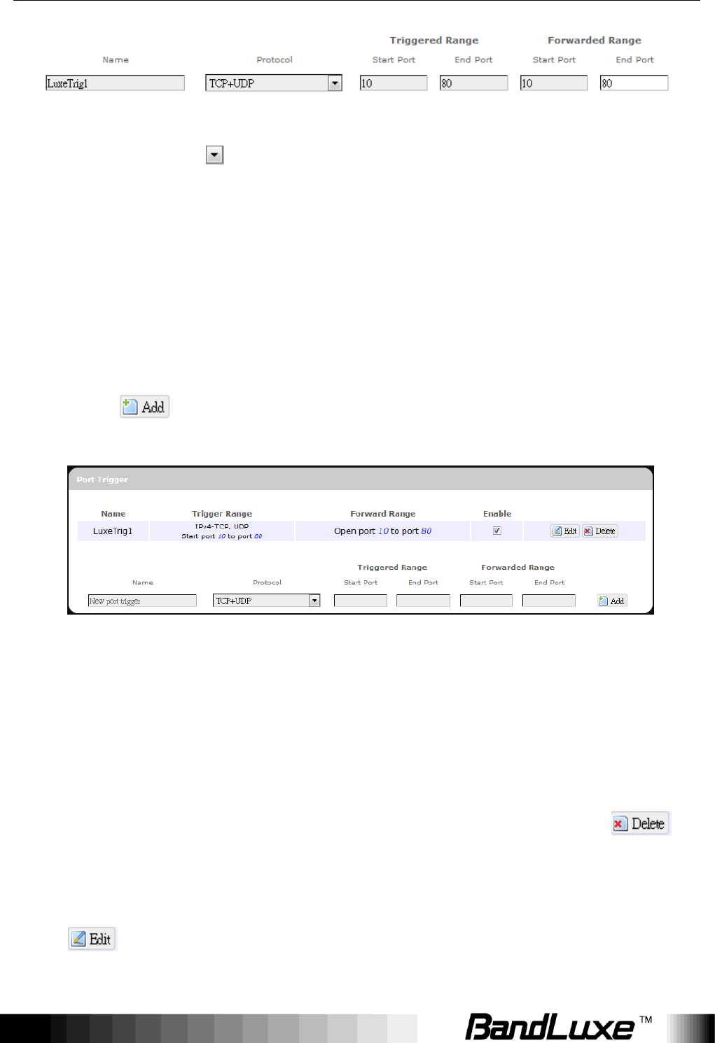
6. More rules can be added to the Port Triggering list by repeating Steps
1-5.
7. (a) To enable or disable a Port Forwards list rule, click its check box
under „Enable‟.
(b) To remove any Port Triggering rule, click its corresponding
button.
8. To edit a particular Port Triggering rule in detail, click its corresponding
button, and the rule‟s associated configuration page (more flexible
and detailed than express settings in Steps 1-4) will appear. After making
(a) (b)
Using Web-based Management
57
any changes, click . Finally click to exit this
configuration page.
Note:
Numerical and text values shown in the illustrative examples are for
demonstration purposes only and are not for actual operation.
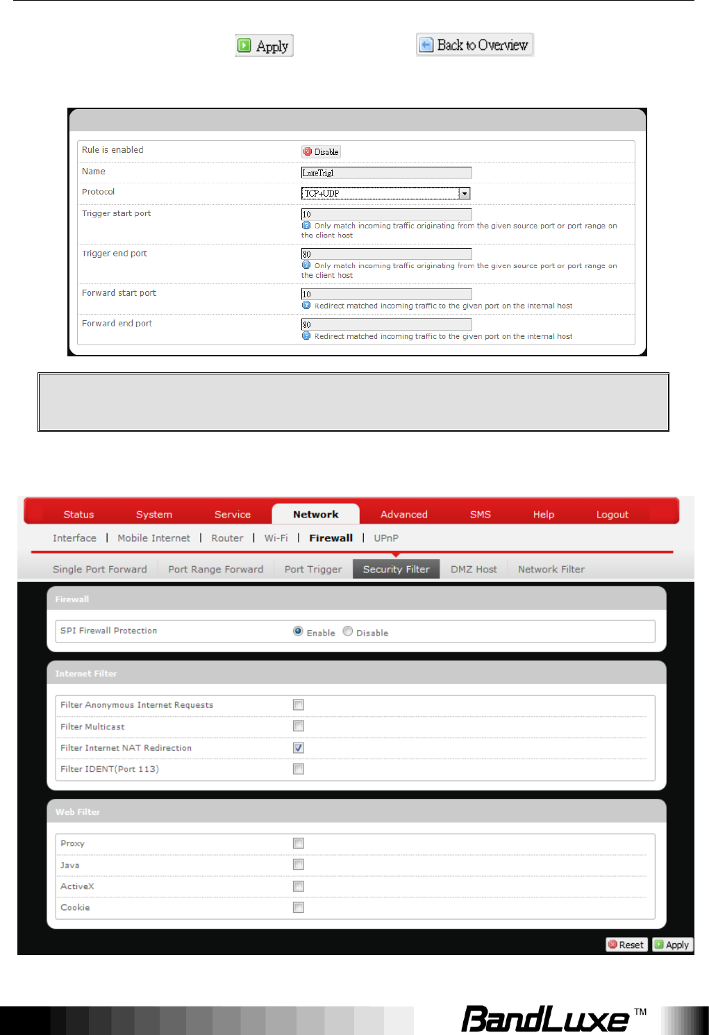
Security Filter

Using Web-based Management
58
Here you can make Firewall, Internet Filter, and Web Filters adjustments for
network security.
Firewall
SPI Firewall
Protection:
Enable or Disable Stateful Packet Inspection (SPI)
feature of the firewall. The default setting is „Enable‟.
Internet Filter
Filter Anonymous
Internet Requests:
This filter blocks anonymous internet requests from
outside network. The default setting is „disabled‟.
Filter Multicast:
Multicasting allows for multiple transmissions to
specific recipients at the same time, i.e. the Router
allows IP multicast packets to be forwarded to the
appropriate computers.
To allow multicasting, disable “Filter Multicast” (this is
the default setting).
To block multicasting, enable “Filter Multicast”.
Filter Internet NAT
Redirection:
This filter blocks local resource access via NAT
(Network Address Translation) redirection (i.e.
external address) from other local computers. The
default setting is „enabled‟.
Filter IDENT
(Port113):
This feature keeps Port 113 from being scanned by
devices outside of your local network. The default
setting is „disabled‟.
Web Filters
Using the Web Filters feature, you may enable up to four specific filtering
methods.
Proxy:
Use of WAN proxy servers may compromise the Router's
security. Select this option to disable access to any WAN
proxy servers.
Java:
Java is a programming language for websites. Select this
option to disable Java. If you disable Java, you run the
Using Web-based Management
59
risk of not having access to Internet sites created using
this programming language.
ActiveX:
ActiveX is a programming language for websites. Select
this option to disable ActiveX. If you disable ActiveX, you
run the risk of not having access to Internet sites created
using this programming language.
Cookies:
A cookie is data stored on your PC and used by Internet
sites when you interact with them. Select this option to
disable cookies.
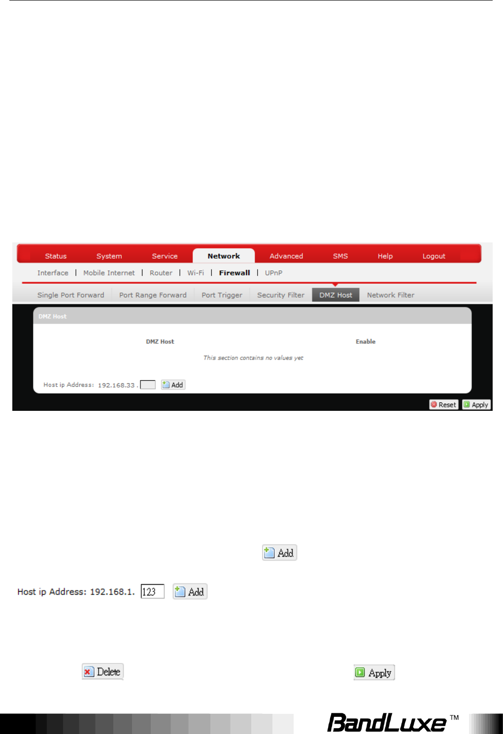
DMZ Host
When a firewall is used, it is sometimes necessary to place some clients (for
example Internet games, video conferencing, or VPN connections) outside of
the firewall while leaving the others protected. You can do this using a
Demilitarized Zone (DMZ). This DMZ Host feature allows you to specify the IP
address of the computers that are placed outside the firewall of your network.
In the text box, enter the last 3 digits of the DMZ host address (the prefix is
192.168.1 for this router), and then click .
The host IP address will be added to the DMZ Host list, which can be further
disabled or enabled by clicking the „Enable‟ checkbox. To remove this DMZ
Host, click . After setting up the DMZ host, click .
Using Web-based Management
60
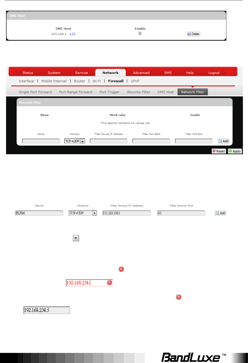
Network Filtering
Network Filtering
Network Filtering allows the Router to discard data from certain IP addresses.
To add a new IP filtering rule:
1. Name: Enter an application name for this IP filtering rule.
2. Protocol: Click and select a protocol from the drop down list –
TCP+UDP (default), TCP, UDP, or Other…
3. Filter Source IP Address: Enter the source IP address to be filtered.
The text color will turn red with on the right for any invalid IP address
entered (e.g. ). When the IP address entered becomes
valid, the text color changes back to black without on the right (e.g.
).
4. Filter Source Port: Enter the source port number to be filtered.
Using Web-based Management
61
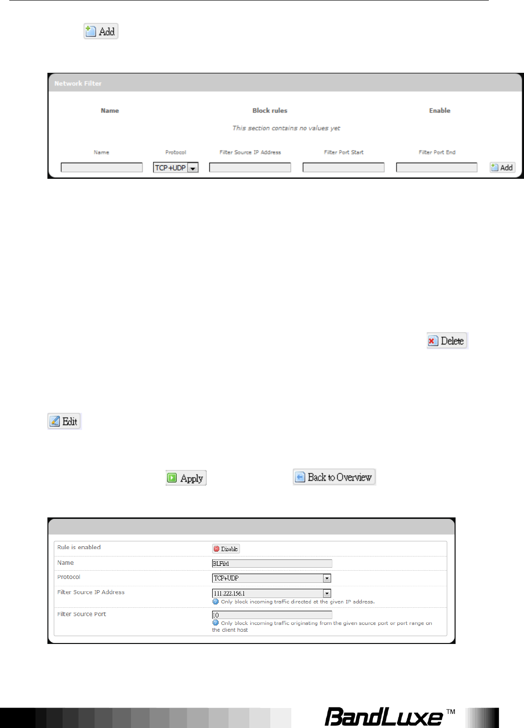
5. Click . The Network filtering rule you have just entered will be
added to the IP Filtering list.
In the status area, the message Unapplied Change may appear next to
“Operator Name” to indicate configuration changes stored in the router.
6. More rules can be added to the network filtering list by repeating Steps
1-5.
7. (a) To enable or disable an network filtering list rule, click its check box
under „Enable‟.
(b) To remove any Port Triggering rule, click its corresponding
button.
8. To edit a particular network filtering rule in detail, click its corresponding
button, and the rule‟s associated configuration page (more flexible
and detailed than express settings in Steps 1-4) will appear. After making
any changes, click . Finally click to exit this
configuration page.
(a) (b)
Using Web-based Management
62
Note:
Numerical and text values shown in the illustrative examples are for
demonstration purposes only and are not for actual operation.
Port Range Forward
UPNP
Universal Plug and Play – Allows wired and wireless network devices to
discover each other and establish network services.
UPnP Settings
Here you can „Enable‟ or „Disable‟ the UPnP service.
Using Web-based Management
63
Advanced
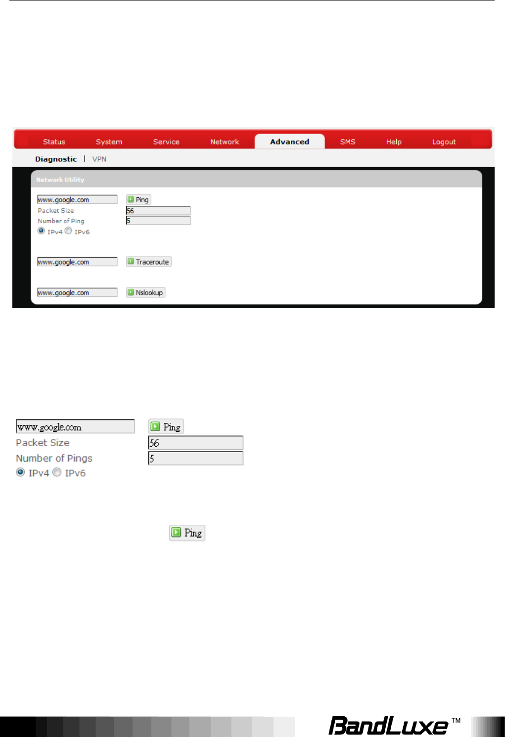
Diagnostics
This menu contains tools for effective network analysis and troubleshooting.
Network Utilities
Ping
This feature allows you to check the status of a connection.
1. In the text box next to , enter the IP address or URL that you want to
ping, and then select its corresponding internet protocol by clicking either
the IPv4 or IPv6 radial button.
2. In the text box of “Packet Size”, enter the desired value (default packet size
is 56).
3. In the text box of “Number of Pings”, enter the number of times you wish to
ping (default value is 5).
Using Web-based Management
64
4. Click to begin the connection status check. „Ping‟ messages will
appear below.
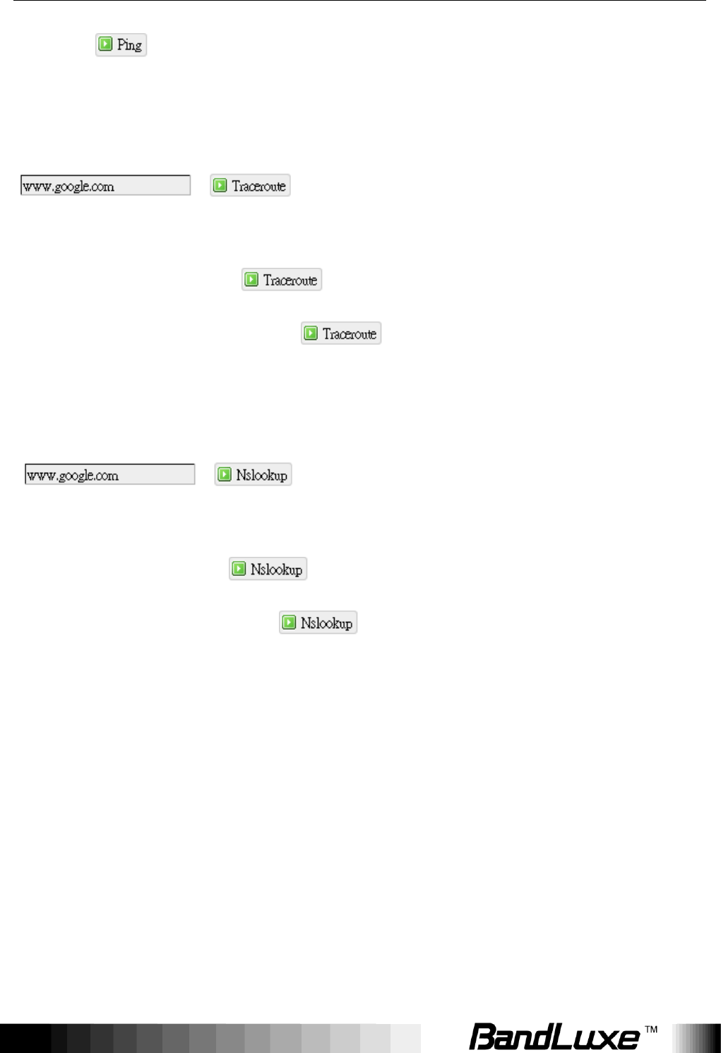
Traceroute
This feature allows you to check the performance of a connection.
1. In the text box next to , enter the IP address or URL that you want
to trace route, and then click to start the performance text.
„Traceroute‟ messages will appear below.
NS Lookup
This feature allows you to retrieve name server information.
1. In the text box next to , enter the IP address or URL that you want to
trace route, and then click to get name server information.
„Nslookup‟ messages will appear below.
SMS
Using Web-based Management
65
Short Message Service – Allows mobile phones and network devices to
exchange short text messages.
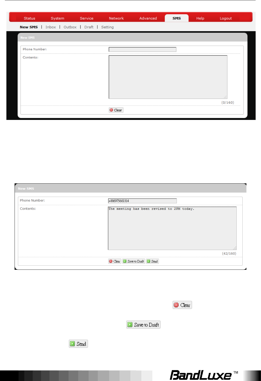
New SMS
Here you can write and send a new SMS message. Enter the recipient‟s phone
number in the field Phone number. Enter message texts in the field Contents.
To erase written contents and start over again, click . To save written
contents as a draft for later use, click . When you are ready to send
the message, click . A confirmation message will appear if the SMS
message is sent successfully.

Using Web-based Management
66
Using Web-based Management
67
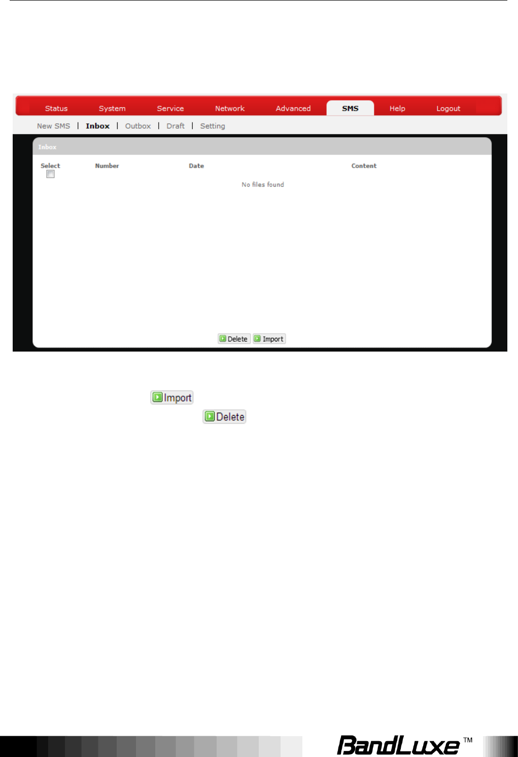
Inbox
Here you can receive and read incoming SMS messages. To get messages
from the server, click . To remove unwanted messages, select
messages to delete and click .
Using Web-based Management
68
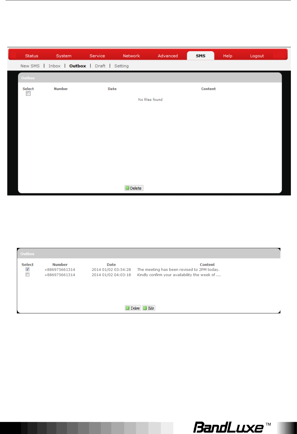
Outbox
Here you can see SMS messages that have been sent out.
To forward a particular SMS message, check only the message of interest
without checking others.
Using Web-based Management
69
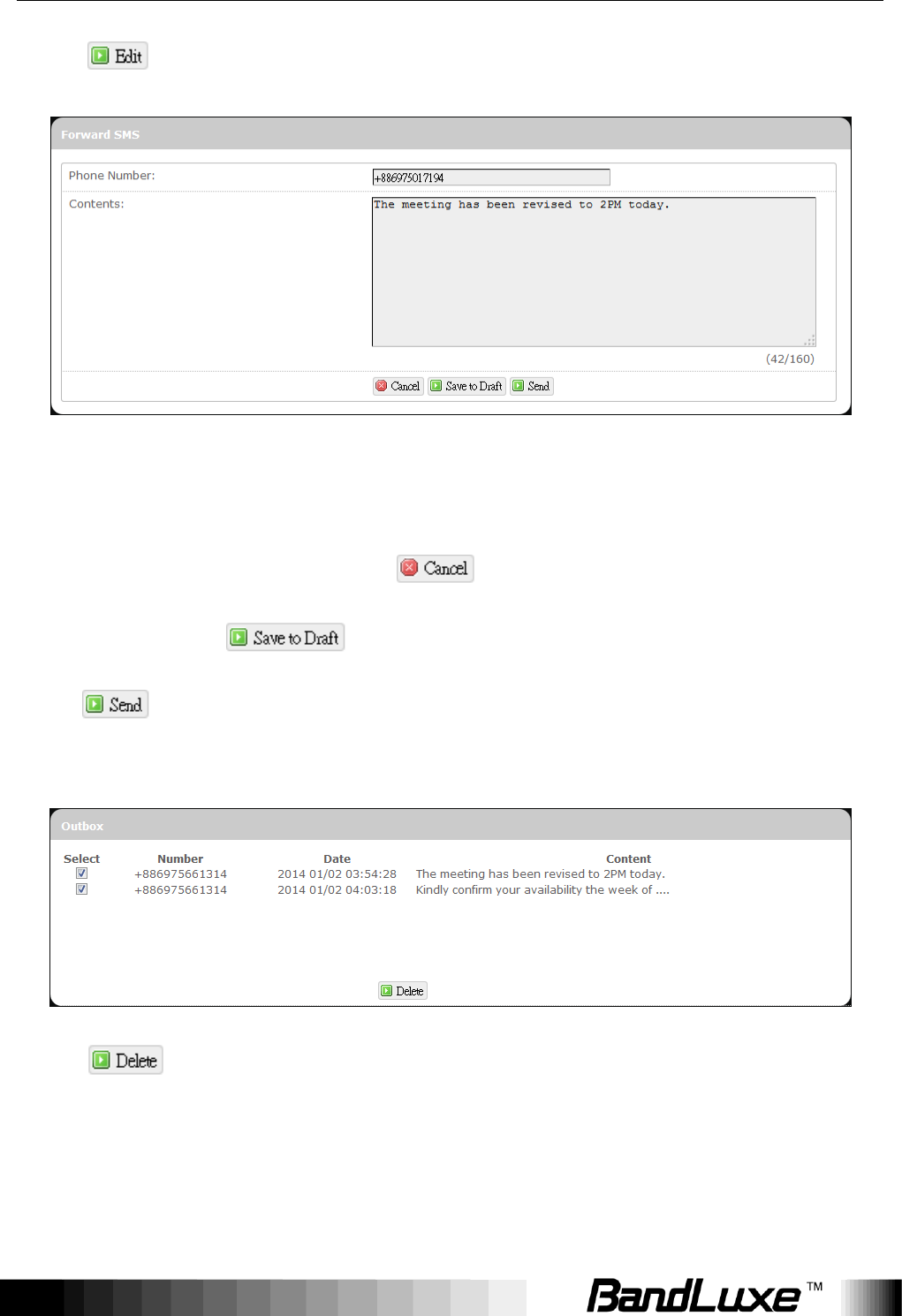
Click .
An additional configuration item Forward SMS will appear on top of the
configuration item Outbox. If necessary, modify the recipient‟s phone number in
the field Phone number or modify message texts in the field Contents. To
cancel message forwarding, click . To save written contents as a draft
for later use, click . When you are ready to forward the message,
click .
To remove SMS messages from Outbox, check the messages to remove.
Click .
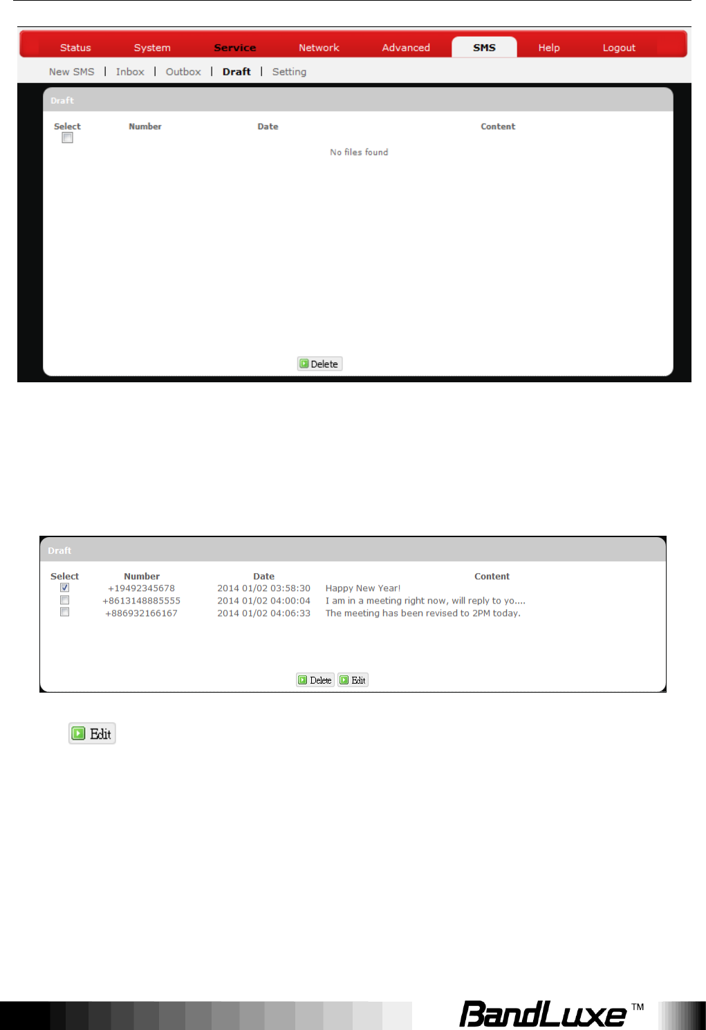
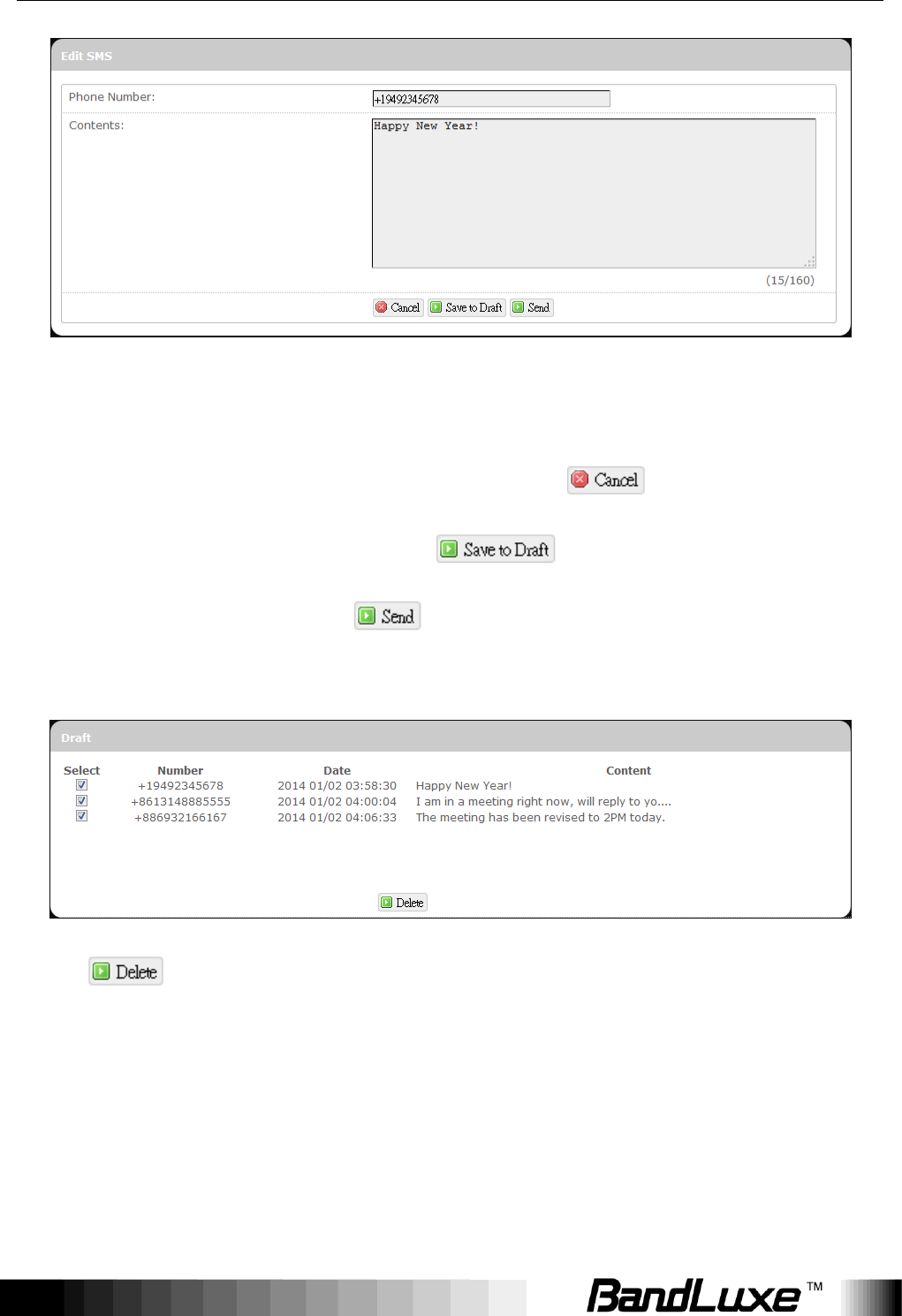
Draft
Using Web-based Management
70
Here you can review and send out SMS messages drafts that have been
previously saved.
To send a particular SMS draft message, check only the message of interest
without checking others.
Click .
Using Web-based Management
71
An additional configuration item Edit SMS will appear on top of the
configuration item Draft. If necessary, modify the recipient‟s phone number in
the field Phone number or modify message texts in the field Contents. To
cancel sending out the SMS draft message, click . To save written
contents as a draft for later use, click . When you are ready to send
the SMS draft message, click .
To remove SMS draft messages from the draft list, check messages to remove.
Click .
Using Web-based Management
72
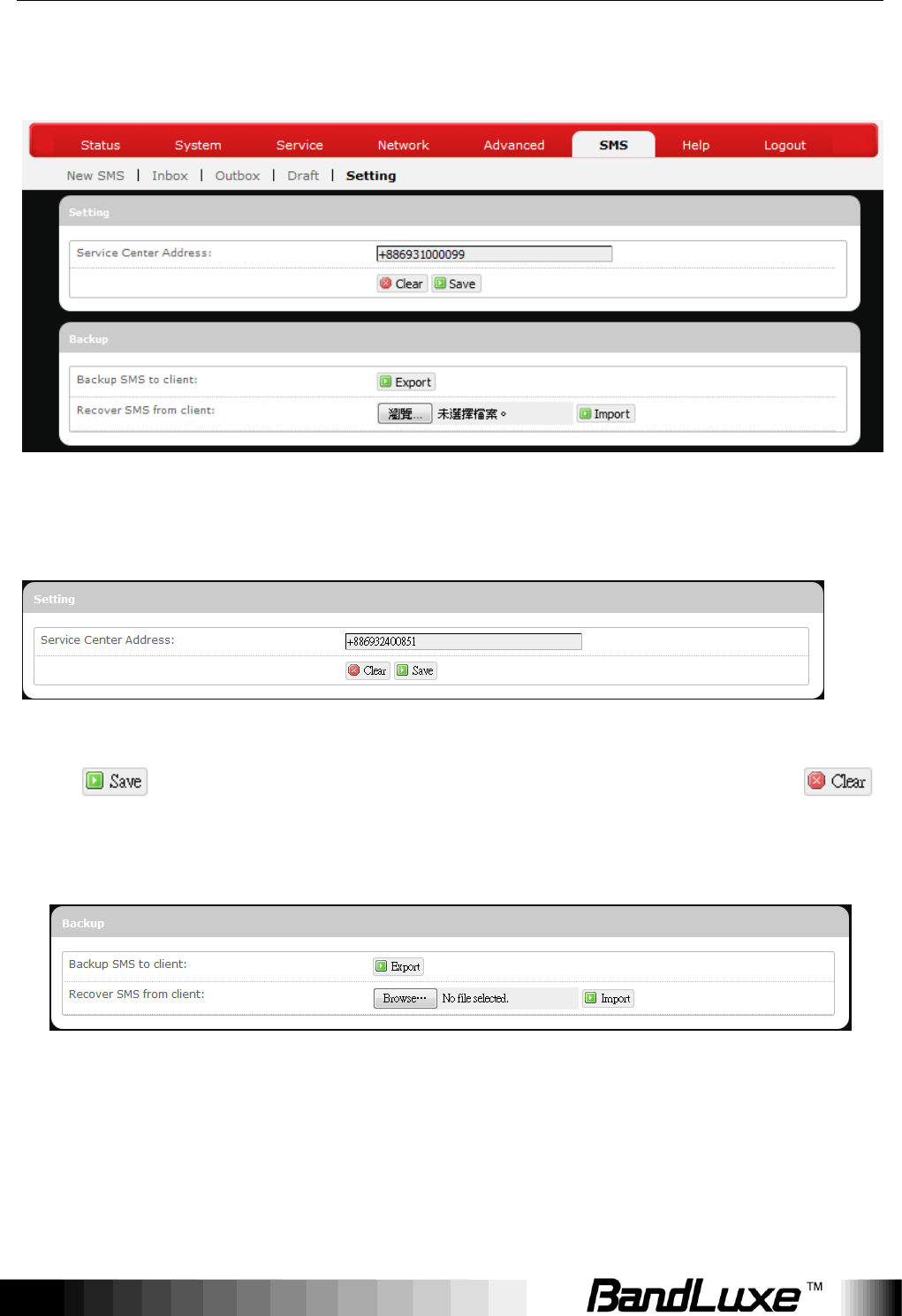
Setting
Here you can configure settings for service center and SMS backup.
Setting
Enter the service center phone number in the field Service Center Address and
click . To clear current phone number and enter a new one, click .
Backup
Using Web-based Management
73
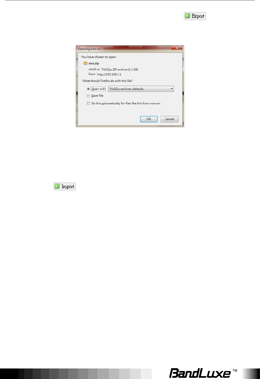
To backup SMS messages to your local computer, click in the field
Backup SMS to client.
Choose Save File, click OK, and follow directions on the screen to save SMS
messages on your local computer as a packed ZIP file.
To recover SMS messages from your local computer, click Browse in the field
Recover SMS from client and select the ZIP file that you have saved previously,
and then click .
Using Web-based Management
74
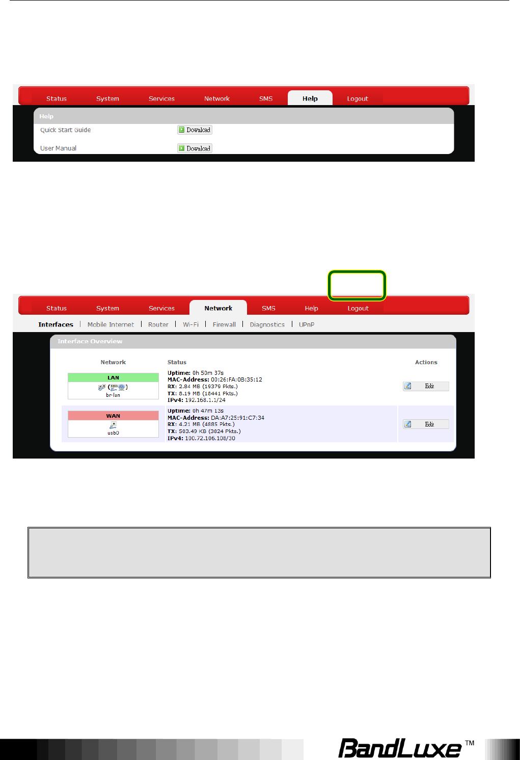
Help
Click the appropriate download link to download the latest Quick Start Guide or
User Manual of this product.
Logout
Exits the web configuration interface and re-directs to login prompt.
Note:
After a period of inactivity, automatic logout will occur. After clicking
any menu item, the login prompt will appear as re-login is needed to
continue using the web configuration interface.

Appendix A: FAQ
75
Appendix A: FAQ
Q: What should I know and how long does it take when I upgrade the firmware
of router or modem?
A: 1. While upgrading the firmware requires some time to finish. During that,
you MUST NOT turn off the power or interrupt the progress.
2. You may use an Ethernet cable or a wireless connection to upgrade the
firmware. We suggest the use of an Ethernet cable.
3. It may take 2 minutes to upgrade the firmware of the router and 5
minutes to upgrade the firmware of the modem.
4. When the firmware of the modem is upgrading, the UMTS LED will flash
among Blue-Green-Red. You should wait until the LED is in single color
(about 4-5 minutes).
Q: How do I connect to the router?
A: 1. Connect an Ethernet cable between PC/Notebook (NB) and the router.
2. Use WiFi to connect.
Q: What‟s the default “User name” and “Password” for the router?
A: User name: admin
Password: admin
Q: How do I enter GUI and setup the configuration for the router?
A: 1. Connect PC/NB to the router.
2. Open Internet Explorer or other Web browser.
3. Input “http://192.168.1.1”.
4. Input User name and Password.
Q: Why can‟t I connect to the network via built-in 3G module?
A: 1. Check the SIM/USIM to see if it is inserted well.
2. Check the UMTS LED on the router to see if it is solid.
3. Check the Status on GUI to see if the SIM/USIM detected well.
4. Check the Status on GUI to see if the APN it is correct.
5. Check the Internet on GUI to see if the Connection is “Keep Alive” or
not.
Appendix A: FAQ
76
Q: Why can't I link on the GUI?
A: If you have changed your WiFi security, SSID, Local IP address, you
have to repair your network to get a new IP that you can link the GUI.
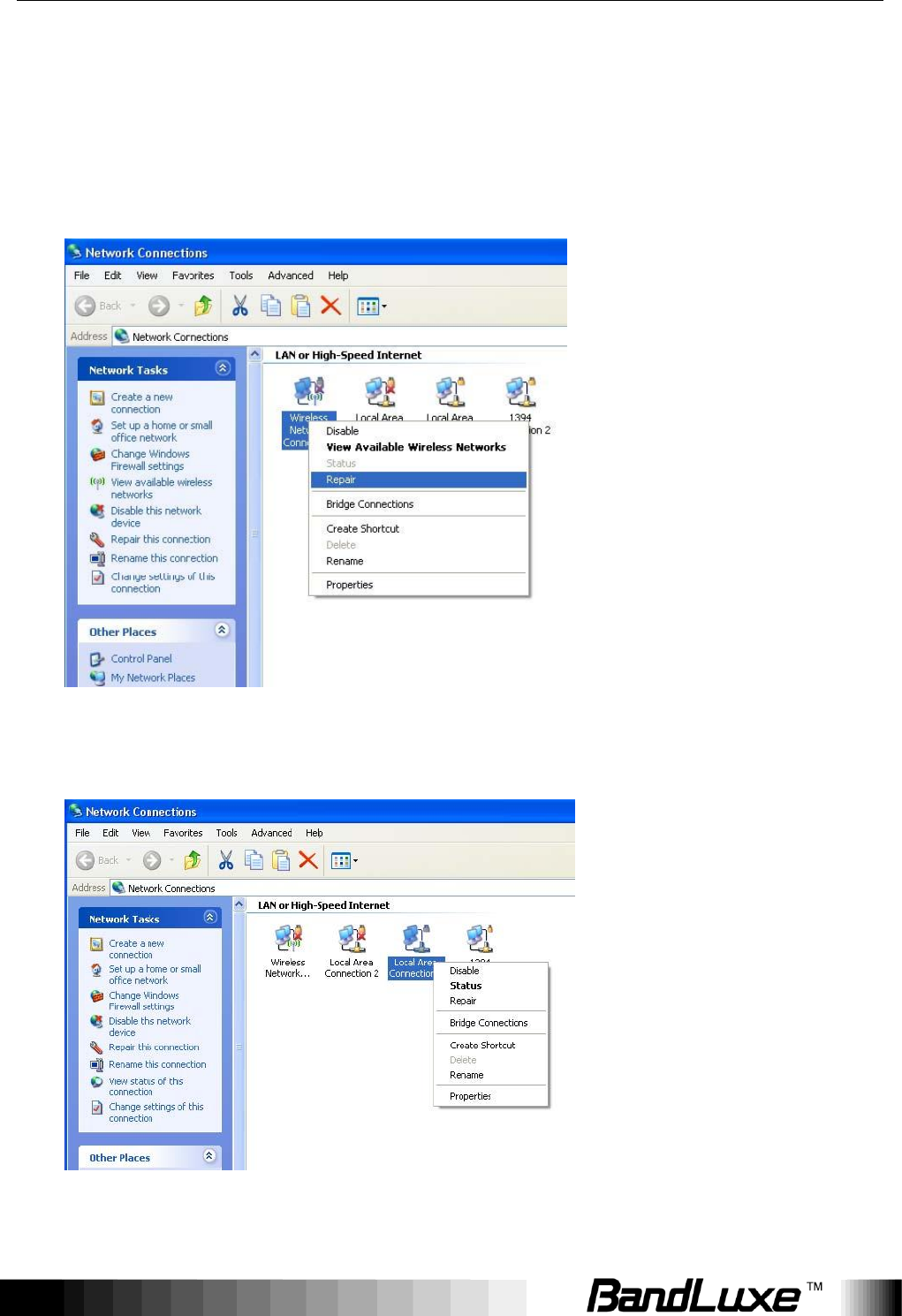
XP:
If you are a WiFi user, click Network Connections and right click on
Wireless Network Connection, click Repair.
If you use Local Area Connection to connect the Router, click Network
Connections and right click on Local Area Connection, click Repair.
Vista/7:
Appendix A: FAQ
77
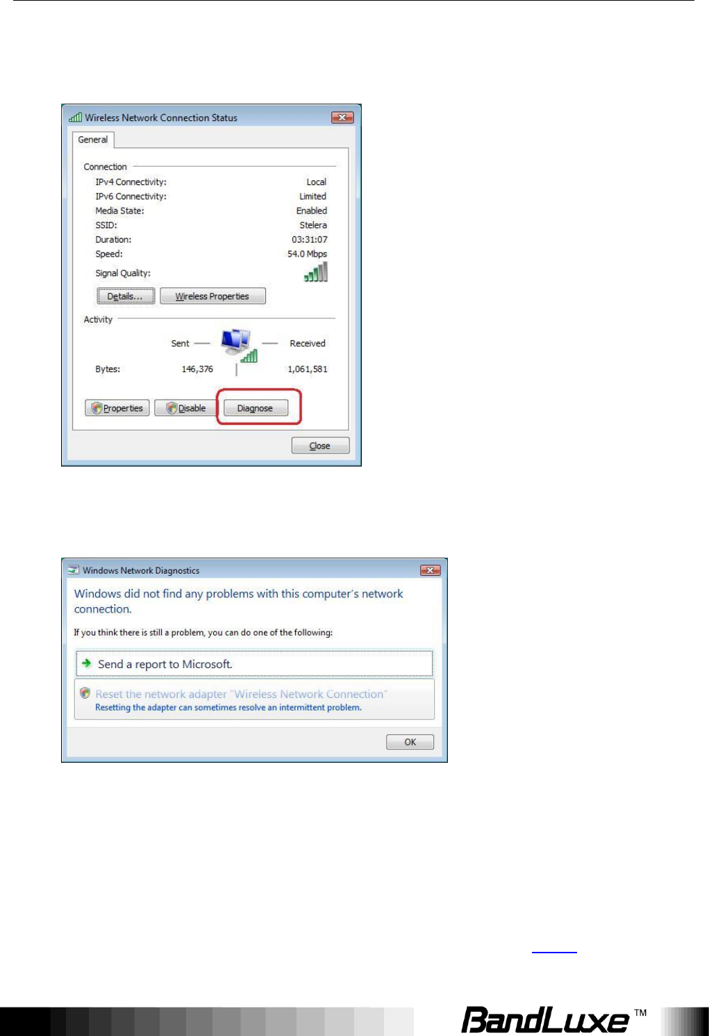
1. If you are a WiFi user, please click Network and Sharing Center >
Manage network connections > Wireless Network Connection >
Diagnose.
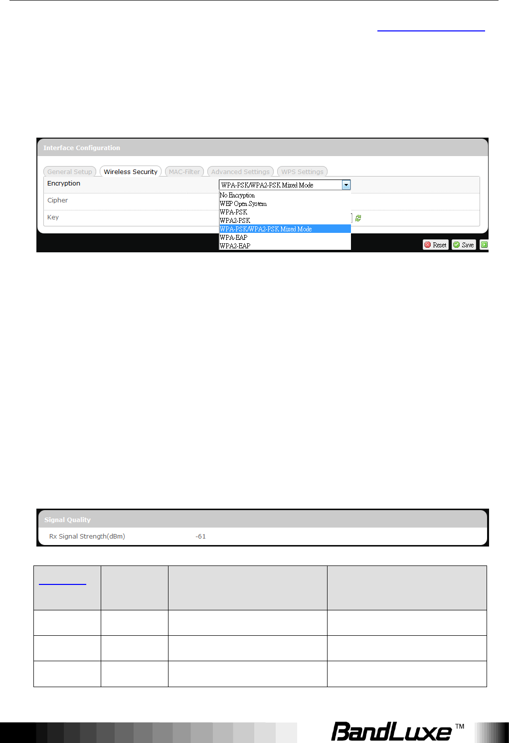
2. Please click Reset the network adapter “Wireless Network
Connection” and it will began to repair.
3. If you use Local Area Connection to connect the Router, please click
Network and Sharing Center > Manage network connections >
Local Area Connection > Diagnose, follow step 1 and the
subsequent messages to repair it.
Q: How do I configure my WiFi settings from GUI?
A: Click the menu tabs Network Wi-Fi to access to the Wi-Fi submenu,
and then click the submenu tab of a particular ESSID.
Appendix A: FAQ
78
If you want to configure WiFi Security please click the “Wireless Security”
tab under “Interface Configuration”.
There are seven wireless security encryption options supported by the
Router: WEP Open System, WEP Shared Key, WPA-PSK, WPA2-PSK,
WPA-PSK/WPA2-PSK Mixed Mode, WPA-EAP, and WPA2-EAP.
Q: How can I have a long-time link?
A: Click the menu tabs Network Router Router Setting. Under “DHCP
Service”, set Client Lease Time to a large value (e.g. 120h = 120 hours = 5
days).
Q: Why can‟t I use the router in the office?
A: Your router‟s IP address might conflict with the office default settings.
Q: Why is my internet speed is so slow with the router?
A: 1. Click the menu tabs Status Mobile Internet to check the Rx Signal
Strength in dBm. Weak signals will significantly slow down internet
speed.
LEDs ON
Signal
Strength
3G WCDMA
RSSI reading
4G LTE
RSRP reading
none
0 bars
Weaker than -100 dBm
Weaker than -115 dBm
#12
1 bar
-100 dBm to (just below) -95 dBm
-115 dBm to (just below) -109 dBm
#12to#13
2 bars
-95 dBm to (just below) -90 dBm
-109 dBm to (just below)) -103 dBm
Appendix A: FAQ
79
#12to#14
3 bars
-90 dBm to (just below) -83 dBm
-103 dBm to (just below) -95 dBm
#12to#15
4 bars
-83 dBm to (just below) -76 dBm
-95 dBm to (just below) -87 dBm
#12to#16
5 bars
-76 dBm or stronger
-87 dBm or stronger
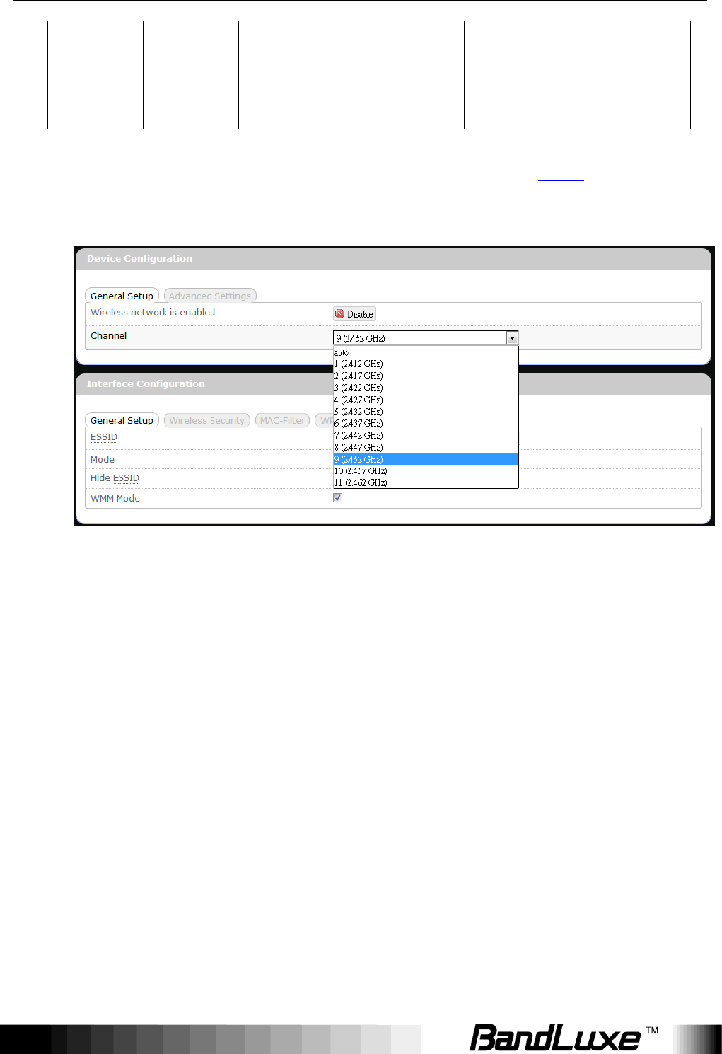
2. Click the menu tabs Network Wi-Fi to access the Wi-Fi submenu,
and then click the submenu tab of the currently used ESSID. Then select
a different WiFi Channel under “Device Configuration.”
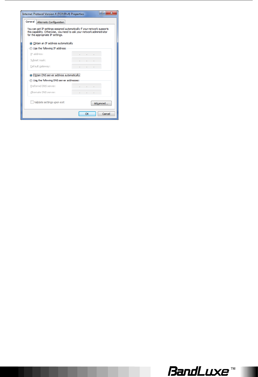
Q: I have connected the computer with the router via LAN connection. Why
can‟t I access the router‟s IP address “http://192.168.1.1” ?
A: Your computer‟s IP address and DNS server addresses may have been
assigned manually. Please set your computer‟s IP address and DNS
server addresses to be obtained automatically. The Windows setup path is:
Control Panel All Control Panel Items Network and Sharing
Center Local Area Connection Properties Internet Protocol
Version 4 (TCP/IPv4)).
Appendix A: FAQ
80
Q: Why can‟t I use VPN via Router?
A: You may check your office IP settings, the IP settings must not conflict with
each other.
Q: How do I configure the settings when I use xDSL to link the router?
A: 1. PPPoE: Go to the GUI Internet > Basic Setting > Ethernet Setting.
Change Connection Type to PPPoE. Enter the Username and
Password provided by your ISP. Remember to connect your xDSL or
Modem to the WAN Port on your Router.
2. Static IP: Go to the GUI Internet > Basic Setting > Ethernet Setting.
Change Connection Type to Static IP. Enter the information in the blank
provided by your ISP. Remember to connect your xDSL or Modem to
the WAN Port on your Router.
Q: Can I prevent others from using my router?
A: Yes, there are some ways to prevent others from using your router.
1. Enable your WiFi client filter.
2. Disabled your SSID Broadcast.
3. Setting your WiFi security.
Appendix A: FAQ
81
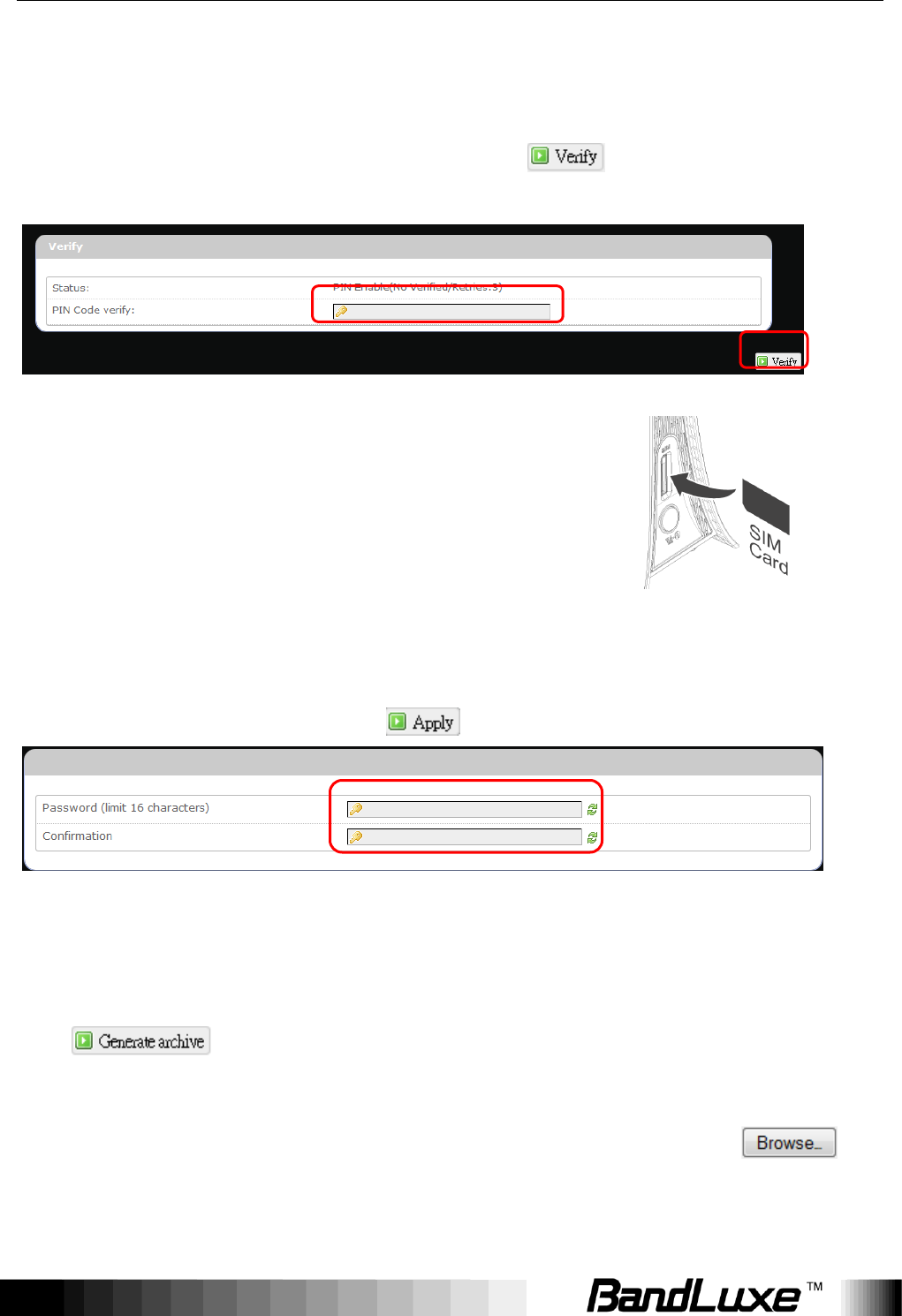
Q: My PIN code is enabled and where can I input the PIN code to use my
Router?
A: Click the menu tabs Network Mobile Internet U/SIM PIN
Management; enter your PIN Code and click .
Q: Why does my U/SIM status display “PIN Disable”?
A: Check that the SIM card (which is properly
activated by your mobile internet service provider) is
inserted correctly in your router.
Q: Where can I change the password of the router?
A: Click the menu tabs System Administration . Enter the new password
twice (set and confirm) and click .
Q: Can I backup and restore all my settings of the router?
A: Yes. Click the menu tabs System Backup / Flash Firmware and click
, then follow instructions on the screen to save router settings
as a TAR file at a desired location on your computer or mobile device.
Conversely, to restore previously saved router settings, click (of
“Restore backup”); follow screen instructions to choose the previously
Appendix A: FAQ
82
saved TAR file; and then click .
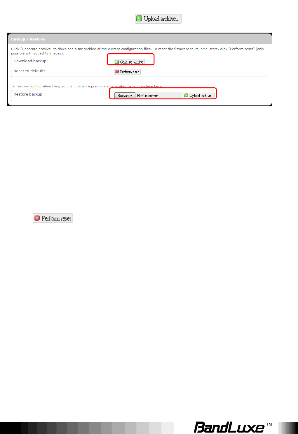
Q: How do I use the Reset button on the router?
A: 1. Short press the Reset button to restart the router.
2. Long press the Reset for more than 10 sec to reset the router to factory
default settings.
Q: Where can I reset the router to factory default settings?
A: 1. Long press the Reset button on the router for more than 10 sec.
2. Click the menu tabs System Backup / Flash Firmware and click
.
Q: If I remove the SIM when 3G is connected, why can‟t I see the SIM status
change?
A: You have to restart the router to see the status. It is best to remove the SIM
card when the router is OFF.

Appendix B: Specifications
83
Appendix B: Specifications
Note: Specifications are subject to change without notice.
Physical
WLAN
802.11 b/g/n (2x2 MIMO)
Cellular modem
Embedded, LTE FDD/DC-HSPA+/HSPA+/HSPA/WCDMA
Dimensions
(LxWxH, mm)
143.6 x 73.3 x 143
Weight (g)
190
Interface
Power On/Off
Switch
Yes
RJ45 Ports
Four LAN ports, each with LED indicator.
Power supply
plug
Yes
SIM slot
Yes
LED Display
Yes, for Network Status, WPS, WiFi, Signal Strength and Power.
SS/WPS/Reset
button
Short press for signal strength indication
Long press (>3s, <10s) for WPS activation
Long press (>10s) for reset to factory default setting
Connectivity and Data Speed
4G LTE Band
Band 2, Band 4
LTE Data Rate
Downlink: up to 100Mbps, Uplink: up to 50Mbps
LTE Bandwidth
Up to 20 MHz
3G WCDMA
Band
Band 2, Band 5, Band 8

Appendix B: Specifications
84
WLAN
802.11 b/g/n, 2x2 MIMO
Antenna
Cellular
embedded main
antenna
Yes
Cellular
embedded
diversity antenna
Yes, supporting LTE bands
Cellular external
main antenna
port
Yes
Cellular external
diversity antenna
port
Yes
WiFi antenna
Embedded
Router Features
Routing
Static Routing, Dynamic Routing (RIP)
Security
Multiple VPN pass-through (IPSec, PPTP, L2TP), Internet Access
Policy (Parental control), Stateless and SPI Firewall
NAT-NAPT
Single Port Forwarding, Port Range Forwarding, Port Range
Triggering, Port Filtering, DMZ, UPnP, Multicast Pass-Through
DNS
DNS Agent, DDNS
Other features
IPv4, IPv6, IPv4v6 dual stack, TCP, UDP, ICMP, ARP, DHCP
Server/Client, HTTP/HTTPs, NTP, ALGs (FTP, PPTP, RTSP)
Browser-based
Administration
GUI
Setup Wizard in GUI.
Browser supported: IE, Firefox, Safari, Chrome
Wireless LAN

Appendix B: Specifications
85
802.11b data
rate
1/2/5.5/11 Mbps
802.11g data
rate
Up to 54 Mbps
802.11n data
rate
Up to 300 Mbps
802.11e QoS
WMM (WiFi Multimedia), No ACK
Security Types
WPA2/WPA/AES/TKIP, WPA/WPA2 PSK mode, None/64/128 bits
WEP Encryption, open system authentication.
Device Unique
Default
Encryption Key
Such unique key is linked to MAC address of the device.
Auto Channel
Select (ACS)
Yes, for channel 1 through 11
Other features
WPS software button, SSID broadcast disable, Guest Network
(Dual SSID), Access control (MAC filter), WLAN on/off software
switch.
Status Indication
LED Display
1x 3-color Network Status
1x Power (also multiplexed with signal strength)
1x WiFi (also multiplexed with signal strength)
1x WPS (also multiplexed with signal strength)
1x SMS (also multiplexed with signal strength)
1x Signal Strength without multiplex
Software Features
Web GUI
Web-based Setup Wizard in GUI.
Browser supported: IE, Firefox, Safari
Web GUI
Language
English

Appendix B: Specifications
86
Support
Connection
Status in Web
GUI
Network name, Signal strength, Roaming indication, Radio
technology, Connection status, Connection time, Total
downlink/uplink byte
Connection
management
Connection on demand, Connection when available, Auto
APN matching with USIM , APN database update through
browser-based GUI, PIN management, Preferred radio NW
type selection, Auto/Manual network selection.
System
protection
Password protected system reset to factory default,
Password protected administrator and user access authority
(provisioning, configuration, authentication).
Support FW
version upgrade
Yes
Device
Management
TR-069
Accessories
Power Adapter
Input: 100to240V, 50to60Hz AC; Output: 9V DC
Environment
Operation
Temperature
0oC to 45oC (32oF to 113oF)
Storage
Temperature
-20oC to 60oC (-4oF to 140oF)
Operating
Humidity
10% to 80% Non-Condensing
Storage
Humidity
5% to 90% Non-Condensing

Appendix B: Specifications
87
Certification
RoHS

Appendix C: Important Safety Information and Glossary
88
Appendix C: Important Safety
Information and Glossary
Europe – EU Declaration of Conformity
European Union Notice
Products with CE marking comply with the R&TTE Directive (99/5/EC), the EMC
Directive (2004/108/EC), and the Low Voltage Directive (2006/95/EC) issued by the
Commission of the European Community.
Compliance with these directives implies conformity to the following European
Norms (in parentheses are the equivalent international standards).
EN 60950-1 (IEC 60950-1)
Safety of Information Technology Equipment.
EN 300 328
Electromagnetic compatibility and Radio spectrum Matters (ERM); Wideband
Transmission systems; data transmission equipment operating in the 2.4 GHz
ISM band and using spread spectrum modulation techniques.
EN 301 489-24
Electromagnetic compatibility and Radio spectrum Matters (ERM);
Electromagnetic Compatibility (EMC) standard for radio equipment and services;
Part 24: Specific conditions for IMT-2000 CDMA direct spread (UTRA) for mobile and
portable (UE) radio and ancillary equipment.
ETSI EN 301 511
Global system for mobile communications (GSM); Harmonised EN for mobile stations in the
GSM 900 and GSM 1800 bands, covering essential requirements of article 3.2 of the R&TTE

Appendix C: Important Safety Information and Glossary
89
directive (1995/5/EC).
ETSI EN 301 489-1
Electromagnetic compatibility and Radio spectrum Matters (ERM);
Electromagnetic Compatibility (EMC) standard for radio equipment and
services; Part 1: Common technical requirements.
ETSI EN 301 489-7
Electromagnetic compatibility and Radio spectrum Matters (ERM);
Electromagnetic Compatibility (EMC) standard for radio equipment and services;
Part 7: Specific conditions for mobile and portable radio and ancillary equipment of digital
cellular radio telecommunications systems (GSM and DCS).
ETSI EN 301 489-17
Electromagnetic compatibility and Radio spectrum Matters (ERM);
Electromagnetic Compatibility (EMC) standard for radio equipment and services;
Part 17: Specific conditions for 2.4 GHz wideband transmission systems.
ETSI EN 301 908-1 & -2
Electromagnetic compatibility and Radio spectrum Matters (ERM); Base Stations (BS),
Repeaters and User Equipment (UE) for IMT-2000 Third Generation cellular networks; Part
1: Harmonised EN for IMT-2000, introduction and common requirements, covering essential
requirements of article 3.2 of the R&TTE Directive.
EN 50385
Product standard to demonstrate the compliance of radio base stations and fixed terminal
stations for wireless telecommunication systems with the basic restrictions or
the reference levels related to human exposure to radio frequency electromagnetic fields
(110 MHz - 40 GHz) - General public.

Appendix C: Important Safety Information and Glossary
90
Federal Communication Commission Interference
Statement
15.21
You are cautioned that changes or modifications not expressly approved by the part
responsible for compliance could void the user‟s authority to operate the equipment.
15.105(b)
Federal Communications Commission (FCC) Statement
This equipment has been tested and found to comply with the limits for a Class B digital
device, pursuant to part 15 of the FCC rules. These limits are designed to provide
reasonable protection against harmful interference in a residential installation. This
equipment generates, uses and can radiate radio frequency energy and, if not installed and
used in accordance with the instructions, may cause harmful interference to radio
communications. However, there is no guarantee that interference will not occur in a
particular installation. If this equipment does cause harmful interference to radio or television
reception, which can be determined by turning the equipment off and on, the user is
encouraged to try to correct the interference by one or more of the following measures:
- Reorient or relocate the receiving antenna.
- Increase the separation between the equipment and receiver.
- Connect the equipment into an outlet on a circuit different from that to which the receiver is
connected.
- Consult the dealer or an experienced radio/TV technician for help.
This device complies with Part 15 of the FCC Rules. Operation is subject to the
following two conditions:
1) This device may not cause harmful interference and
2) This device must accept any interference received, including interference that may cause
undesired operation of the device.
FCC RF Radiation Exposure Statement:
This equipment complies with radio frequency (RF) exposure limits adopted by the

Appendix C: Important Safety Information and Glossary
91
Federal Communications Commission for an uncontrolled environment. This equipment
should operate with minimum distance 20 cm between the radiator & your body.

Appendix C: Important Safety Information and Glossary
92
Glossary
2G: Second-generation mobile networking technology. Represents a switchover from analog
to digital; most 2G networks use GSM.
3G: Third-generation mobile networking technology that enables simultaneous transfer of
voice and non-voice data; most 3G networks use WCDMA.
3.5G: A more recent standard of mobile networking technology; generally uses HSDPA.
3.75G: A more recent standard of mobile networking technology; generally uses HSUPA.
4G: A more recent standard of mobile networking technology; generally uses LTE.
APN (Access Point Name/Network): Provides GPRS routing information. Consists of:
Network ID: Identifies the external service requested by a GPRS user.
Mobile network operator ID: Specifies routing information.
ARFCN (Absolute Radio Frequency Channel Number): The specific ID numbers for all
radio channels used in cellular mobile communications.
bps (bits per second): How data flow is measured.
CHAP (Challenge Handshake Authentication Protocol): CHAP identifiers are changed
frequently and authentication can be requested by the server at any time.
DNS (Domain Name System): Helps route network traffic by making the addressing
process more user-friendly.
DHCP (Dynamic Host Configuration Protocol): How devices obtain IP addresses from a
server.
DUN (Dial-Up Network): Windows component that enables online access via a modem.
EDGE (Enhanced Data GSM Environment/Enhanced Data for Global Evolution):
Advanced GPRS that delivers multimedia and other data needing greater bandwidth at
up to 237 kbps.
GPRS (General Packet Radio Service): Delivers data in packets at up to 86 kbps.
GSM (Global System for Mobile Communications): The most popular cellular network,
mostly operates in 850-900 or 1800-1900 MHz; the primary 2G system.
HSDPA (High Speed Downlink Packet Access): Advanced WCDMA that delivers downlink

Appendix C: Important Safety Information and Glossary
93
bandwidth intensive data at up to 7.2Mbps; typically associated with 3.5G.
HSUPA (High Speed Uplink Packet Access): Advanced WCDMA that delivers uplink
bandwidth intensive data at up to 5.76Mbps; typically associated with 3.75G.
HSPA+ (High Speed Packet Access +): This is also known as HSPA Evolved, is the next
step and is more focused on delivering data services enabling speeds of up to 42Mbps
in the downlink and 11Mbps in the uplink.
IMEI (International Mobile Equipment Identity): A number unique to each GSM/UMTS
device that can be used block network access by a stolen mobile device.
IP (Internet Protocol): Routes packets over a network.
Kbps (Kilobits per second): A data flow measure; 1024 bits/second.
LAN (Local Area Network): A data network with limited range but good bandwidth.
Mbps (Megabits per second): A data flow measure; 1,048,576 bits/second.
LTE (Long Term Evolution): High-speed mobile communication standard based on the
GSM/EDGE and UMTS/HSPA network technologies. LTE provides downlink peak rates
up to 300 Mbit/s and uplink peak rates up to 75 Mbit/s.
PAP (Password Authentication Protocol): The difference between PAP authentication
and a manual or scripted login, is that PAP is not interactive. The username and
password are entered in the client's dialing software and sent as one data package as
soon as the modems have established a connection, rather than the server sending a
login prompt and waiting for a response.
PPP (Point-to-Point Protocol): An internet connection method.
PIN (Personal Identity Number): Four to eight digital numbers SIM card security code;
allows access to the carrier‟s network.
Rx: Shorthand for Reception.
SIM (Subscriber Identity Module): A small card that contains key mobile device
identification, subscription and contact information.
Tx: Shorthand for Transmission.
WCDMA (Wideband Code Division Multiple Access): Advanced EDGE that supports
384kbps data flow. Most 3G networks use this standard, the same as UMTS.