BarMate BARMATE-SAM BARMATE SYSTEM - SAM User Manual BarMate Installation Guide
BarMate Limited BARMATE SYSTEM - SAM BarMate Installation Guide
BarMate >
Contents
- 1. BarMate Installation Guide
- 2. BarMate User Manual
BarMate Installation Guide

“Poolside Service at the Touch of a Button”
Installation Guide
Rev A

“Poolside Service at the Touch of a Button”
Installation Guide
Rev. A
ii BarMate Installation Guide
BarMate Installation Guide iii
Notice
This guide is provided for informational use only. Every effort was made to ensure
accuracy of information in this guide at the time of printing. BarMate reserves the right to
provide updates to content information not available at the time this guide was printed.
Changes or modifications to the BarMate System not expressly approved by BarMate
could void the user’s authority to operate the equipment.
Copyright
2008 BarMate Ltd. All rights reserved. BarMate and its logo are trademarks of BarMate.
All other trademarks and registered trademarks are the property of their respective
owners. No part of this guide may be reproduced manually or electronically without
written permission from BarMate.
Trademarks
BarMate is a trademark or registered trademark of BarMate in the United States,
European Union and/or other countries.
Federal Communications Commission (FCC) Notice
The BarMate system complies with part 15 of the FCC Rules. Operation is subject to the
following two conditions: (1) This device may not cause harmful interference, and (2) this
device must accept any interference received, including interference that may cause
undesired operation.
The Service Request Device (SRD) and the Service Area Manager (SAM) have been
tested and found to comply with the limits for a Class A digital device, pursuant to part 15
of the FCC Rules. These limits are designed to provide reasonable protection against
harmful interference when the equipment is operated in a commercial environment. This
equipment generates, uses, and can radiate radio frequency energy and, if not installed
and used in accordance with the instruction manual, may cause harmful interference to
radio communications. Operation of this equipment in a residential area is likely to cause
harmful interference in which case the user will be required to correct the interference at
his own expense.
The Gateway has been tested and found to comply with the limits for a Class B digital
device, pursuant to part 15 of the FCC Rules. These limits are designed to provide
reasonable protection against harmful interference in a residential installation. This
equipment generates, uses and can radiate radio frequency energy and, if not installed
and used in accordance with the instructions, may cause harmful interference to radio
communications. However, there is no guarantee that interference will not occur in a
iv BarMate Installation Guide
particular installation. If this equipment does cause harmful interference to radio or
television reception, which can be determined by turning the equipment off and on, the
user is encouraged to try to correct the interference by one or more of the following
measures:
• Reorient or relocate the receiving antenna.
• Increase the separation between the equipment and receiver.
• Connect the equipment into an outlet on a circuit different from that to which the
receiver is connected.
• Consult the dealer or an experienced radio/TV technician for help.
CE Compliance
The BarMate System has been designed and tested to be CE compliant under the
R&TTE Directive.

BarMate Installation Guide v
Important Safety Instructions
When installing/using this product, basic safety precautions should always be followed to
reduce the risk of fire, electric shock and injury to persons, including the following:
1. Read and understand all instructions.
2. Do not use the Gateway near water.
3. Clean only with dry cloth.
4. Do not locate the antenna near overhead light or power circuits, or where it can
fall into such power lines or circuits. When installing the antenna, take extreme
care to avoid touching such power lines or circuits, as contact with them can be
fatal.
5. Refer all servicing to qualified service personnel. Servicing is required when the
equipment has been damaged in any way and does not operate normally.
SAVE THESE INSTRUCTIONS

vi BarMate Installation Guide
Symbols
Failure to comply with safety precautions in this guide violates the intended use of this
product. The following safety symbols appear in this guide:
GENERAL HAZARD
This symbol represents a general warning or caution.

BarMate Installation Guide vii
About This Guide
Purpose and scope
The purpose of this guide is to introduce the BarMate system and to help you
successfully setup and install this product. The scope of this guide describes the BarMate
System, components, and capabilities, and provides instruction for installing, setting up,
operating, and verifying installation and operation of the system once installed.
Audience
This guide is intended for trained BarMate Installers. It is assumed that installers have
been trained, and have a basic understanding of the BarMate System and installation
process when installing a system.
Organization
The following table is a roadmap to using this guide efficiently.
Refer to… To…
Chapter 1, The BarMate Overview Understand the BarMate System and how it
functions
Chapter 2, Installation Install the BarMate system components
Chapter 3, Management Centre Setup and
Operation
Setup and operate the BarMate software.
This section also describes how to upload
and configure maps, calibrate a SAM, and
configure an SRD.
Appendix A, BarMate Site Survey See an example survey
Appendix B, Specifications Understand cable wiring and pinouts
Acronyms See a list of the acronyms used in this
guide and the words they represent.
Related information
Use this guide in conjunction with a completed BarMate site survey. The site survey form
is located on page 4 of this guide.

Contents
viii BarMate Installation Guide
Conventions
The following table describes typographical and icon conventions used throughout this
guide.
Description Example
A switch you press on a device appears in
this TYPEFACE.
Press the START switch.
Text you must enter exactly as shown
appears in this typeface.
Type a:\set.exe in the dialog box.
A greater than symbol (>) indicates
choosing a submenu from a menu.
On the status bar, choose Start > Settings
>Network Connections.
A plus sign (+) indicates simultaneous
keystrokes.
Press Ctrl+s.
A comma (,) indicates consecutive
keystrokes.
Press Alt+f, s
An arrow represents a tip or conveys
related information. ►
BarMate Installation Guide ix
Contents
Chapter 1 BarMate Overview .................................................................. 4
About BarMate............................................................................................... 4
How BarMate works...................................................................................... 4
System description ....................................................................................... 4
Technical description of system components ......................................... 4
BarMate software.................................................................................... 4
Chapter 2 Installation .............................................................................. 4
Site survey overview..................................................................................... 4
Installation overview..................................................................................... 4
Required tools ......................................................................................... 4
Before installation.................................................................................... 4
BarMate system contents ............................................................................ 4
Installation guidelines .................................................................................. 4
Installing Gateway......................................................................................... 4
Installing the BarMate software................................................................... 4
Launching the Management Centre Application ....................................... 4
Installing the Solar Panel ............................................................................. 4
Mounting an Antenna Array......................................................................... 4
Assembling a linear antenna array ......................................................... 4
Assembling a square array ..................................................................... 4
Mounting a COM Antenna ............................................................................ 4
Installing a SAM ............................................................................................ 4
Installing the battery................................................................................ 4
Mounting the SAM .................................................................................. 4
x BarMate Installation Guide
Connecting the Antenna Array, COM Antenna, and Solar Panel........... 4
Installing SRDs.............................................................................................. 4
SRD orientation....................................................................................... 4
SRD attachments.................................................................................... 4
Disconnecting an SRD from a Bracket Mount ........................................... 4
Chapter 3 Management Centre Setup and Operations......................... 4
Setting up the Management Centre............................................................. 4
Setting up maps ............................................................................................ 4
About map files ....................................................................................... 4
Uploading and configuring maps ............................................................ 4
Configuring the SAM .................................................................................... 4
Identifying the SAM in the BarMate software.......................................... 4
Configuring an SRD for calibration ......................................................... 4
Calibrating the SAM ................................................................................ 4
Reconfiguring the SRD for operation...................................................... 4
Overview of the Management Centre Application Interface ..................... 4
Map tab ................................................................................................... 4
Service Requests tab.............................................................................. 4
Waiter Config tab .................................................................................... 4
MC Config tab ......................................................................................... 4
SAM Config tab....................................................................................... 4
SRD Config ............................................................................................. 4
Messages tab.......................................................................................... 4
Settings tab ............................................................................................. 4
Appendix A BarMate Site Survey Example ........................................... 4
Appendix B: Square Array Drawing Specification................................ 4
Acronyms ................................................................................................. 4
BarMate Installation Guide 1
Chapter 1 BarMate Overview
This chapter provides an overview of the BarMate system.
Topics discussed in this chapter include the following:
• About BarMate on page 4
• How BarMate works below
• System description on page 4
o Technical description of system
componentson page 4
o BarMate software on page 4

Chapter 1 BarMate Overview
2 BarMate Installation Guide
About BarMate
BarMate is a wireless system that allows guests to request
bar service with the press of a button. The wireless device
sends a request for service signal to a nearby bar. Service is
then provided by a waiter/waitress. After providing prompt
service, the waiter/waitress clears the signal indicating the
guest has been served.
The BarMate system is designed to be scalable, flexible, and
accurate for any resort environment.
How BarMate works
To request service, a guest presses a button on a Service
Request Device (SRD), which sends a signal to the
Management Centre (MC) or the Master Management
Centre (MMC), usually located at the bar or refreshment
area to request service. The Management Centre consists of
a Gateway and a touchscreen personal computer (PC)
running BarMate software. A Waiter will identify the location
of the guest using the BarMate software, and promptly
respond to the guest requesting service. An LED will
illuminate on the SRD to help identify the guest requesting
service. After responding to a guests request for service, the
Waiter clears the signal on the SRD to indicate the guest has
received the requested service. Clearing the signal will
switch the LED on the SRD off and send relevant service
data (date and time service request was fulfilled) to the
Management Centre.
Wireless communications between the SRD and the
Gateway are managed by the Service Area Manager (SAM),
inconspicuous devices located between the SRDs and the
MC to manage wireless communication traffic between
devices and assist with identifying the guests’ location.
Chapter 1 BarMate Overview
BarMate Installation Guide 3
System description
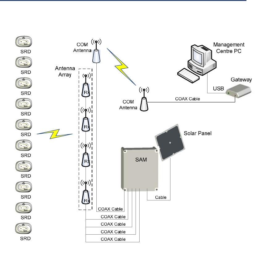
The following diagram illustrates the BarMate System. A
description of system components follows.
Figure 1: System Block Diagram.
Chapter 1 BarMate Overview
4 BarMate Installation Guide
Technical description of system components
The BarMate system sends and receives data using multiple
devices. Each device is described below.
Service Request Device (SRD) – A push button device that
Transmits (TX) and Receives (RX) a signal to and from the
Service Area Manager (SAM). An LED (Light Emitted
Device) illuminates on the SRD, indicating service request.
The illuminated LED identifies the guest requesting service
and also lets the guest know the SRD is active. This is a
battery powered, wireless device that attaches to a surface,
typically on a sun lounger.
Service Area Manager (SAM) – A device that manages
service requests from SRDs. The SAM transmits and
receives signals to and from SRDs using the Antenna Array.
The SAM also uses a COM antenna to transmit and receive
signals between the SAM and the Gateway. The SAM is
powered with a battery that can be recharged using a solar
panel and cable. For environmental protection against
outdoor elements, the SAM shell (box casing) is a NEMA 4
rated enclosure.
Antenna Array – Composed of four antennas that connect
to a SAM. The array transmits and receives signals between
SRDs and a SAM. The array locates the SRD requesting
service by triangulation.
COM Antennas – Connect to the SAM and to the Gateway
(one antenna for each device) by coaxial cable. The COM
antennas transmit and receive signals between the Gateway
and the SAM.
Solar Panel – Connects to the SAM to recharge the battery.
Gateway – Communicates wirelessly with one or more
SAMs using a COM antenna. The Gateway is part of the
Management Centre (MC) and connects to the MC computer
using a USB cable. The COM antenna attaches to the
Gateway with a coaxial cable.
Management Centre (MC) – Composed of a Gateway and a
touchscreen computer running the BarMate software. The
MC is usually located in the bar area, and provides the
Chapter 1 BarMate Overview
BarMate Installation Guide 5
interface between the BarMate system and the site’s wait
staff. A site may have multiple MCs. The MC computer
connects to the Gateway with a USB cable.
Master Management Center (MMC) – Like the MC, the
MMC is composed of a Gateway and a touchscreen
computer running the BarMate software. At sites that have
multiple MCs, the MMC routes messages between MCs as
required. The MMC can also function as an interface
between the BarMate System and the site’s wait staff.
BarMate software
The BarMate software runs on the MC or MMC computer.
The BarMate software enables waiters to identify the
location of guests requesting service and to indicate when
the guest has been served. The BarMate software enables
Administrators to manage and assign waiters at specific MC
locations.
This section will include a table, as well as a graphic with a
Chapter 1 BarMate Overview
6 BarMate Installation Guide
Chapter 2 Installation
BarMate Installation Guide 7
Chapter 2 Installation
This chapter describes how to install the BarMate system.
Topics discussed in this chapter include the following:
• Site survey overview on page 4
• Installation overview on page 4
o Required toolson page 4
o Error! Reference source not found.Before
installationon page 4
• BarMate system contents on page 4
• Installation guidelines on page 4
• Installing Gatewayon page 4
• Installing the BarMate software on page 4
• Launching the Management Centre Application on
page 4
• Installing the Solar Panel on page 4
• Mounting an Antenna Array on page 4
o Assembling a linear antenna array on page 4
o Assembling a square array on page 4
• Mounting a COM Antenna on page 4
• Installing a SAM on page 4
Chapter 2 Installation
8 BarMate Installation Guide
o Installing the battery on page 4
o Mounting the SAM on page 4
o Connecting the Antenna Array, COM
Antenna, and Solar Panel on page 4
• Installing SRDs on page 4
• Disconnecting an SRD from a Bracket Mount on
page 4

Chapter 2 Installation
BarMate Installation Guide 9
Site survey overview
Before the BarMate system is installed, a site survey should
be completed by BarMate-trained personnel. The site survey
involves examining the installation site, and determining the
number of BarMate devices needed, where the devices
should be located, and how they should be mounted.
For example, the site survey should identify the number of
SRDs, SAMs, solar panels, Gateways, and MCs needed for
a particular site. Also, the survey should identify the type of
antenna arrays (square or linear) needed, and the cable
lengths necessary to connect devices. The survey should
also note where each device will be mounted and the
hardware and tools necessary to mount the device.
Information from the site survey should be recorded on the
site survey form located on page 4 of this guide. If more
space is needed to record information, additional pages can
be stapled to the site survey form.
► Note: BarMate devices, such as SRDs, solar panels, and
antennas, include mounting brackets and screws.
However, depending on the requirements of a particular
site, additional hardware and tools may be required.
Any additional hardware and tools required for installation
should be noted on the site survey.
Installation overview
Each installation of the BarMate system will be based on the
BarMate site survey (see “Site survey overview” on page 4
and the site survey form on page 4).
This guide describes installation of a basic system. Refer to
the completed site survey form for the number of SAMs,
SRDs, and Gateways to be installed at a specific site. The
site survey also specifies the cable lengths required between
components and the approximate location where
components should be installed.

Chapter 2 Installation
10 BarMate Installation Guide
► Note: The BarMate system is for industry/commercial use,
and installation of the system requires specific knowledge
and training. For these reasons, the BarMate system
should only be installed by personnel who have been
trained by BarMate to install the system.
Required tools
Installation of the BarMate system requires the following
tools:
► Note: Depending on the requirements of a particular site,
additional tools and hardware may be required. Any
additional tools or hardware should be noted on the site
survey.
• Screw driver
• Drill
• Electrical tape
• Wire splicer
• Refer to the site survey for additional tools and hardware
that may be needed for a specific site.
Before installation
Before you begin installing the BarMate system, complete
the following tasks:
• Make sure you have a completed site survey.
• Use the completed site survey to verify that you have the
items required for installation (for example, the correct
number of BarMate system components, any additional
mounting hardware and tools).
Chapter 2 Installation
BarMate Installation Guide 11
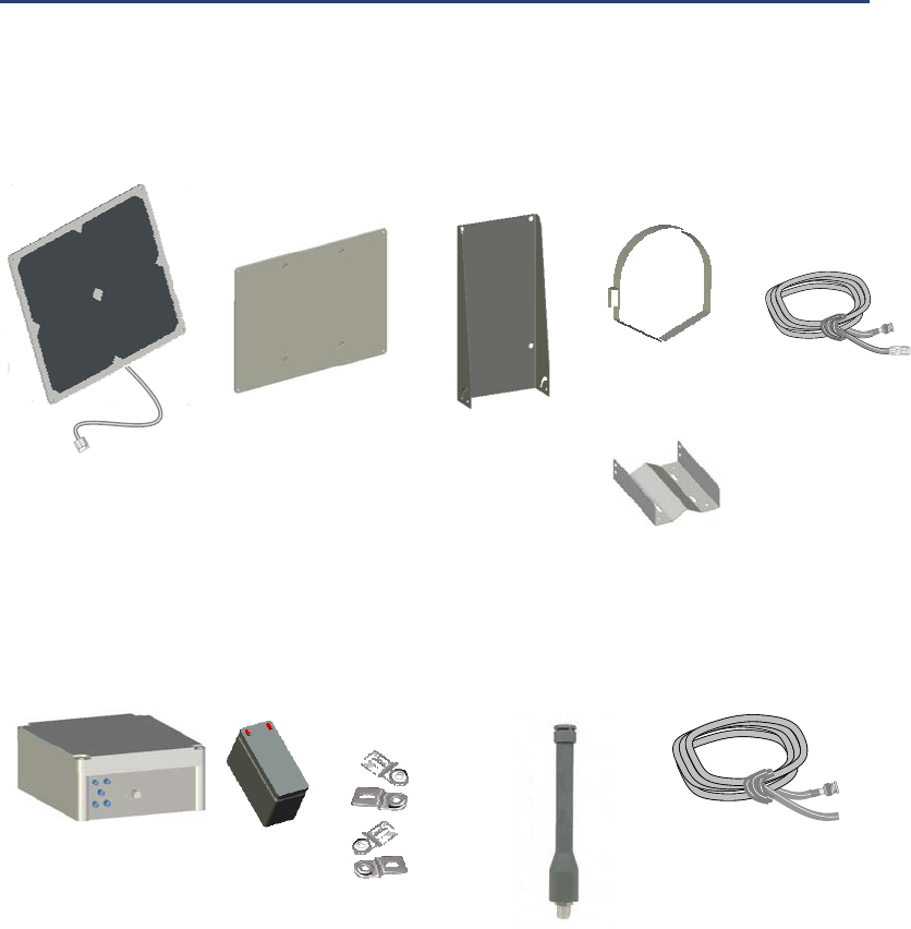
BarMate system contents
The BarMate system includes the following components.
See the site survey for quantities and installation plan for a
specific site.
Solar Panel Assembly
(2) Hose
Clamps
(1) Solar Panel
with Power Cable
(1) Solar Panel
Mount
and 4 screws
(1) Small
Mounting Bracket
and (4) screws
(1) Pole Mount
and (4) screws
(1) Power
Extension Cable
with Cable-to-
Cable connectors
SAM
(1) SAM with cover
and
(4) screws
(1) Battery (4) Mounting
Bracket and
screws
(1) COM Antenna,
(1) Heavy-duty
steel bracket,
(2) U-bolts
(1) Coaxial cable
(See site survey for
cable lengths)
Chapter 2 Installation
12 BarMate Installation Guide
Antenna Array
Square Array may include:
(1) Mast
(4) Horizontal Tubes
(2) Plexi-glass plates with ¼ - 20
bolts, washers, and nuts
(4) Antennas and
(2) brackets per
antenna
(4) Coaxial cables
(See site survey for
cable lengths)
See site survey for Square Array
& Appendix B Drawing
Specification
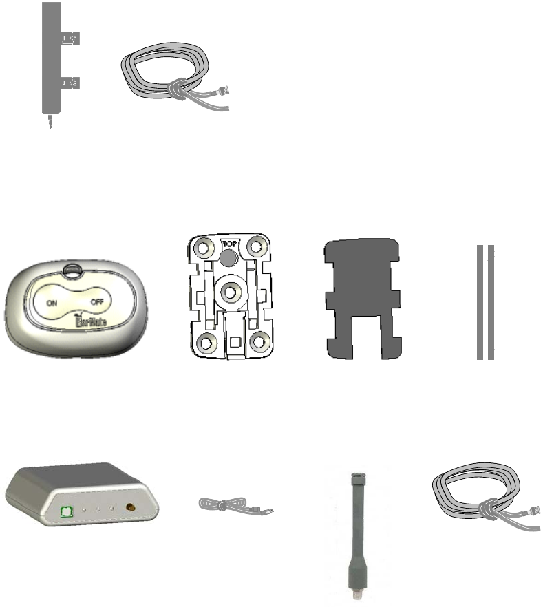
SRD (see site survey for details)
(1) SRD SRD Mounting Bracket
with (4) screws
SRD Mounting
Adhesive
Tie-Wraps
(2 per SRD)
Gateway and related components
(1) Gateway (1) USB Cable
Assembly
(1) COM Antenna
(1) Heavy-duty steel
bracket
(2) U-bolts
(1) Coaxial cable
(See site survey for
cable lengths)

Chapter 2 Installation
BarMate Installation Guide 13
Installation guidelines
When installing the BarMate system, some devices should
be mounted and powered on before others. The following
guidelines indicate the order in which devices should be
mounted or powered.
• Mount the solar panels, antenna array, and COM
antennas before connecting them to their respective
devices.
• Power up the Gateway, launch the Management Centre
(MC) application, and then power up the SAM. Powering
up the devices in this order allows the SRDs to be
registered into the system. If a SAM is powered up
before the Gateway and the MC application are started,
the SAM will have to be powered down, and then
repowered in order for the SRDs to be registered in the
system.
• If there are multiple SAMs, power up the SAM closest to
an active Gateway first. When a SAM is powered up, it
must be in range of an active Gateway or another active
SAM that is in range of an active Gateway.
• Before powering all the SRDs (snapping them into their
mounting brackets), calibrate the SAM with a single
SRD. After the SAM is calibrated, the other SRDs can be
powered on. For more information about calibrating, see
“Configuring the SAM” on page 4.
Chapter 2 Installation
14 BarMate Installation Guide
Installing Gateway
Generally, the Gateway will be located next to the
Management Centre PC. Refer to the site survey for the
exact location. Also, the Gateway’s COM antenna should be
mounted before it is connected to the Gateway.
CAUTION:
The Gateway can be damaged if it gets wet. Do not place
liquids on this device or allow liquids to accidentally spill on this
device.
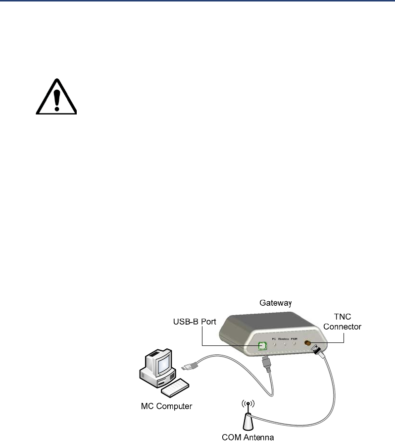
To install Gateway
1 Place the Gateway near the PC to which it will be
connected. It is recommended that the Gateway is
placed in an elevated position with a good line of sight to
at least one SAM.
2 Connect the coaxial cable to the N-Female connector on
the COM Antenna. Connect the other end of the cable to
the TNC connector on the Gateway.
3 Connect one end of the USB cable to the USB port on
the computer. Connect the other end to the USB-B port
on Gateway.
Figure 2: Gateway connections.
Chapter 2 Installation
BarMate Installation Guide 15
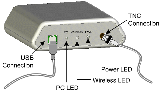
4 Verify that the LEDs illuminate green to indicate
successful connection and communications.
Figure 3: Gateway LEDs and connections.
• PC LED: Illuminates green to indicate successful
communications between Gateway and PC.
• Wireless LED: Illuminates green to indicate successful
wireless communications.
• Power LED: Illuminates green to indicate Gateway is on.

Chapter 2 Installation
16 BarMate Installation Guide
Installing the BarMate software
The following procedure describes how to install the
BarMate software from a CD.
To install the BarMate software
1 Insert the BarMate CD into the Master Management
Centre computer’s disk drive.
2 From the Windows Start key, select Run.
3 In the Run dialog box, type D:\BarMateSetup.exe
and click OK.
The setup utility begins to install the BarMate
Management Centre (MC) application. An icon is placed
on the desktop and a BarMate menu option is inserted
on the Windows Start menu.
Launching the Management Centre Application
After the BarMate software is installed, you can launch the
Management Centre application.
To launch the Management Centre application
1 Click the BarMate icon on the desktop, or click the
Windows Start menu and select Programs > BarMate.
A prompt displays asking if you want to configure the
Management Centre.
2 Select one of the following options:
a. To configure the Management Centre at a later
time, click No. The Management Centre’s Map
tab displays.
b. To configure the Management Centre now, click
Yes. See “Setting up the Management Centre”
on page 4.
Chapter 2 Installation
BarMate Installation Guide 17
Installing the Solar Panel
If specified in the site survey, a solar panel can be used to
recharge the battery in the SAM. Solar panels should be
mounted before they are connected to a SAM.
To install a solar panel
1 Assemble the Solar Panel and mounting assembly:
a. Attach the solar panel to the Large Panel Mount
with the 4 screws.
Figure 4: Solar panel and large panel mount.
Attach with
screws
Chapter 2 Installation
18 BarMate Installation Guide
b. Attach Small Mount to rear of Solar Panel
Assembly with 4 screws.
Figure 5: Solar panel assembly and small mount.
Attach with
screws
Chapter 2 Installation
BarMate Installation Guide 19
c. Attach Solar Panel Assembly to the Small Post
Mount with 4 screws.
► Note: Tighten screws to secure panel, while allowing ability
to adjust solar panel when Solar Panel Assembly is
secured to a fixed object, such as a pole, wall, or roof.
Figure 6: Solar panel assembly and small post mount
2 Mount the Solar Panel Assembly to a fixed object such
as a pole, roof, or wall.
► Note: Solar Panel should be located and angled to receive
a minimum of 6 hours of direct sunlight (see BarMate site
survey).
Attach with
screws, not
too tight—
allow for
panel
adjustment
Chapter 2 Installation
20 BarMate Installation Guide
3 Secure Solar Panel Assembly and post mount to pole
using 2 hose clamps.
Figure 7: Small post mount attached to pole.
4 Adjust Solar Panel to have an unobstructed view of the
sun, and tighten Small Mount screws to secure Solar
Assembly in position.
Small Mount
screws secure
position of the
Solar Panel
Assembly
Hose clamps
thread through
bracket inserts
Chapter 2 Installation
BarMate Installation Guide 21
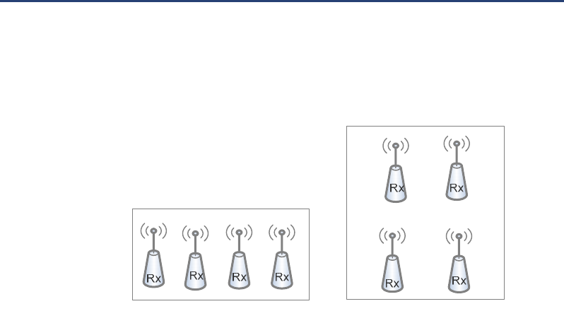
Mounting an Antenna Array
The antenna array is composed of four antennas that
connect to a SAM. There are two types of arrays: a Linear
Array and Square Array. (See Error! Reference source not
found.) Refer to the site survey for guidance on the type of
array to install.
Figure 8: Linear and Square Arrays.
The antenna array should be connected to the SAM only
after the SAM and the antennas have been mounted. The
following procedures describe how to assemble both a linear
and a square array.
Assembling a linear antenna array
The site survey should indicate where and how the antennas
will be mounted. The following procedure describes how to
assemble a linear antenna array.
To assemble a Linear Array
1 Attach Antenna enclosures to surface with brackets in a
straight line. Refer to site survey for distance between
antennas.
2 Attach coaxial cable to the antenna enclosure and dress
cable as described in site survey.
Square Array
Linear Array
Chapter 2 Installation
22 BarMate Installation Guide
3 After the SAM is mounted and operational, connect the
antennas in the array to the SAM. See “Installing a SAM”
on page 4.
Assembling a square array
The site survey should indicate where and how the array is
to be mounted. The following procedure describes how to
assemble a square antenna array.
To assemble a Square Array
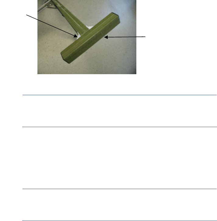
1 Attach four 4-hole corner brackets to Mast (long,
grooved aluminium pole).
2 Create a “X” with (1) long and (2) shorter horizontal
tubes. The smaller #8 tapped holes face outside of the
“X”.
► Note: The shorter horizontal tubes have large holes for
connecting to the Mast and smaller #8 tapped holes for
connecting Antenna Enclosures.
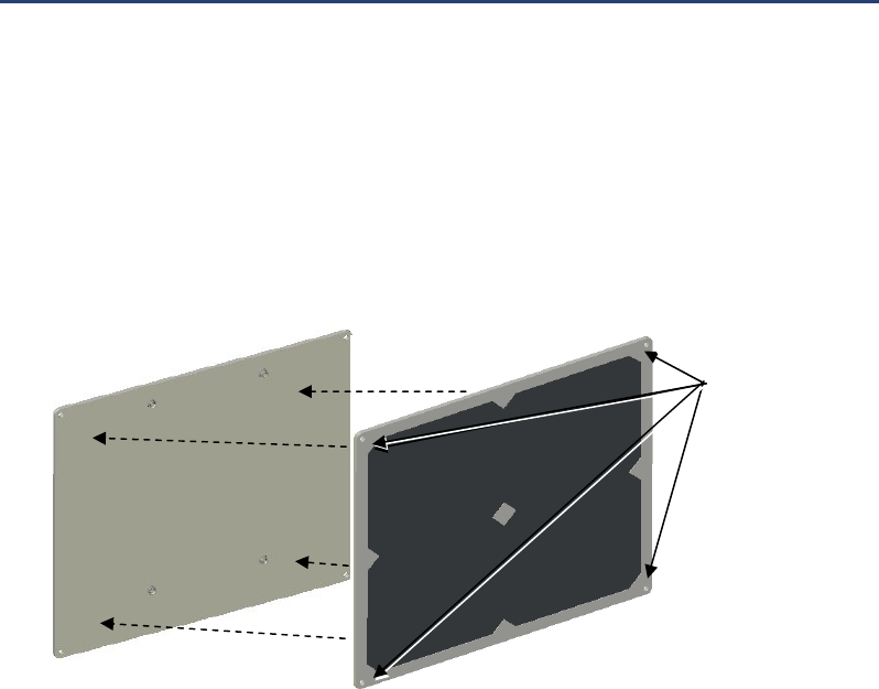
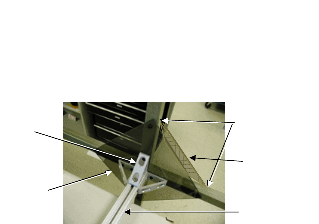
3 Place a plexi-glass plate on top of the “X” and one plexi-
glass plate underneath of the “X”.
Figure 9: Plexi-glass plates, mast, and horizontal tubes.
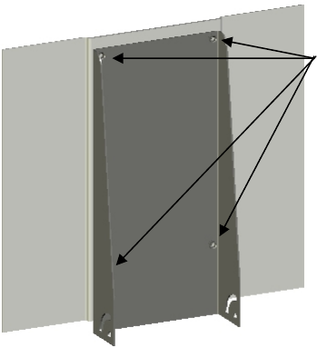
4 Attach horizontal-plexi-glass assembly to corner
brackets on Mast subassembly using ¼-20 bolts,
washers, and nuts.
Horizontal Tubes
Mast
4-Hole Corner
Bracket
Plexi-glass Plate below
Horizontal Tubes
Plexi-glass Plate
on top of
Horizontal Tubes
Chapter 2 Installation
BarMate Installation Guide 23
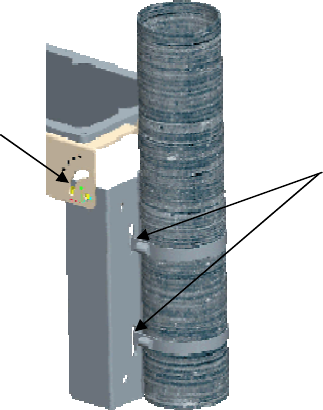
5 Use brackets on antenna enclosures to attach RX
antenna enclosures to each end point on the “X”; attach
the TX antenna enclosure at a to-be-determined point
specified by the site survey.
Figure 10: Antenna enclosure and brackets.
► Note: When the Antenna Array is fully assembled and
mounted, the antenna enclosures should be perpendicular
to the ground with the SMA connector pointing downward
towards the ground.
6 Attach coaxial cable to the SMA jack on the antenna
enclosure.
7 Use cable clamps to dress cables underneath horizontal
tube to centre of Mast, and then run cable down the
groove in the vertical Mast and out to the SAM.
► Note: Each antenna must have an unobstructed view of
the SRD. If an object, such as a structure or tree, is
between the components it may interrupt wireless
communications (see BarMate site survey).
8 After the SAM is mounted and operational, connect the
antennas in the array to the SAM. See “Installing a SAM”
on page 4.
Bracket
Antenna
Enclosure

Chapter 2 Installation
24 BarMate Installation Guide
Mounting a COM Antenna
The SAM and Gateway each require their own COM
Antenna. A COM antenna can be mounted on a pole or a flat
surface. The included U-bolts allow installation on poles up
to 2.0 inches in diameter. Additional hardware may be
needed to mount the COM antenna to a flat surface. See the
BarMate site survey to determine where the COM antenna
should be mounted and what hardware is needed. The
following procedure describes how to mount the antenna to
a pole.
► Note: The COM Antennas for the Gateway and SAM
should be mounted before they are attached to their
respective devices. Also, the Gateway and SAM should be
installed and operational before they are connected to their
COM Antennas.
To mount the COM Antenna
1 Use two U-bolts to attach the mounting bracket to the
pole.
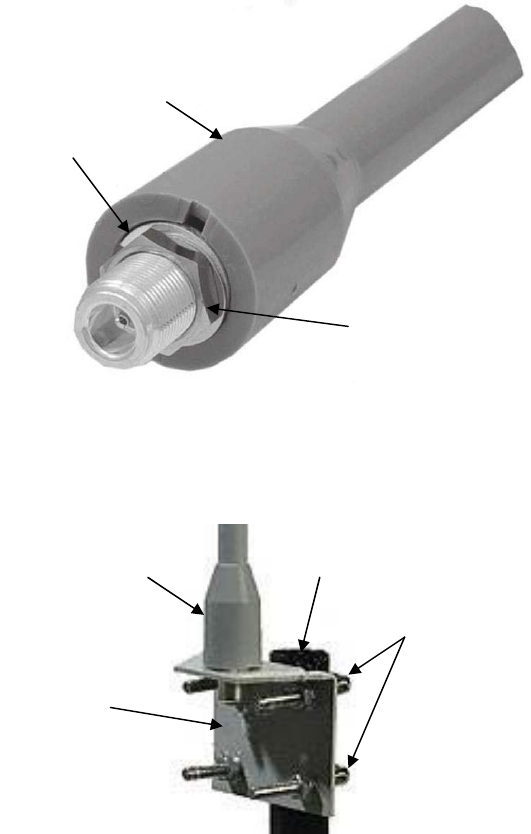
2 Remove the mounting nut and washer from the base of
the antenna. See Figure 11 on page 4.
Chapter 2 Installation
BarMate Installation Guide 25
Figure 11: COM antenna base.
3 Insert antenna into mounting bracket and secure with
washer and antenna mounting nut. Do not over tighten.
Figure 12: COM antenna and mounting bracket.
4 After the COM antennas are mounted and their
associated devices (SAM and Gateway) are installed
and operational, connect the COM antennas to their
respective devices. For information about installing the
devices, see “Installing Gateway” on page 4 and
“Installing a SAM” on page 4.
Antenna
Bracket
U-bolts
Pole
Antenna
Mounting Nut
Washer

Chapter 2 Installation
26 BarMate Installation Guide
Installing a SAM
Each SAM is connected to an Antenna Array (four
antennas), a COM Antenna, and a solar panel. Each of
these items should be mounted before they are connected to
the SAM.
Installing the SAM involves the following tasks:
• Installing a battery
• Mounting the SAM
• Connecting the Antenna Array, COM Antenna, and Solar
Panel.
► Note: Installing the SAM involves powering on the device.
However, you should power up the Gateway and launch
the Management Centre application before powering on the
SAM. Powering up the devices in this order allows the
SRDs to be registered into the system. If a SAM is powered
up before the Gateway and Management Centre
application are started, the SAM will have to be powered
down, and then repowered in order for the SRDs to be
registered in the system.
If there are multiple SAMs, power up the SAM closest to an
active Gateway first. When a SAM is powered up, it must
be in range of an active Gateway.
Each time a SAM is powered on, a prompt will display in
the Management Centre asking you to configure the SAM
now or later. See “Configuring the SAM” on page 4.
Chapter 2 Installation
BarMate Installation Guide 27
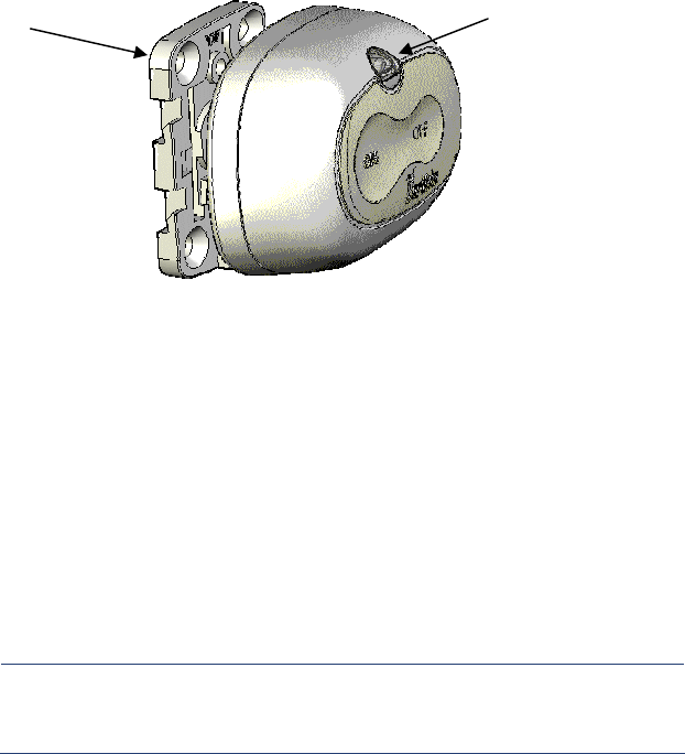
Installing the battery
To prevent damage during shipping, the SAM is shipped
without its battery in place. The following procedure
describes how to install the battery.
CAUTION:
The Management Centre (Gateway and computer) must
be powered and set-up before power is applied to the
SAM.
To install the battery
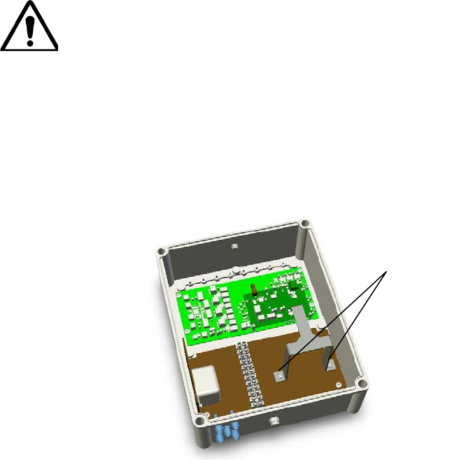
1 Remove the four screws from the SAM cover; and then
remove the cover.
2 Remove the two screws that secure the battery bracket.
Figure 13: Battery bracket and screws inside SAM.
3 Insert the 12V Power Up battery (P/NPUBP-7-12 or
equivalent).
4 Connect the red (positive) battery cable to the red fast-
on connector on the battery. Connect the black
Bracket
screws
Chapter 2 Installation
28 BarMate Installation Guide
(negative) battery cable to the black fast-on connector
on the battery.
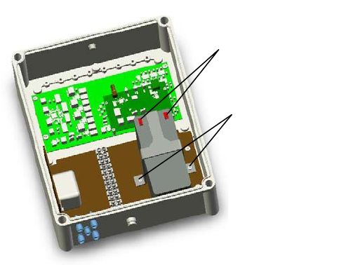
5 Replace the battery bracket and secure with the two
bracket screws.
Figure 14: Battery installed in SAM.
Bracket Screws
Battery cable
fast-on connectors
Chapter 2 Installation
BarMate Installation Guide 29
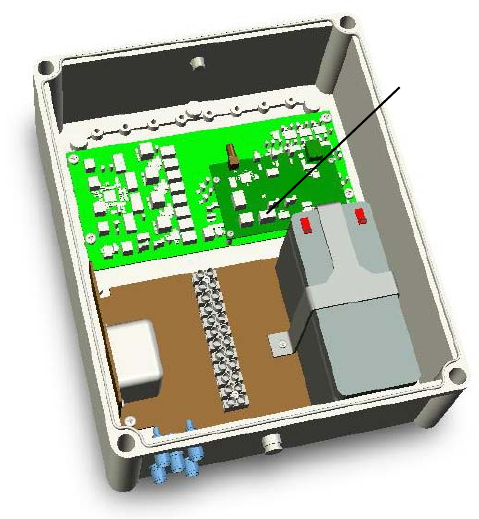
6 Make sure the Management Centre (Gateway,
computer, and software) are running, and then, on the
small PC Board in the SAM, switch the power to ON.
Figure 15: On/Off switch inside SAM.
7 Replace SAM cover and secure with four cover screws.
OFF/ON
switch
Chapter 2 Installation
30 BarMate Installation Guide
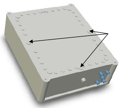
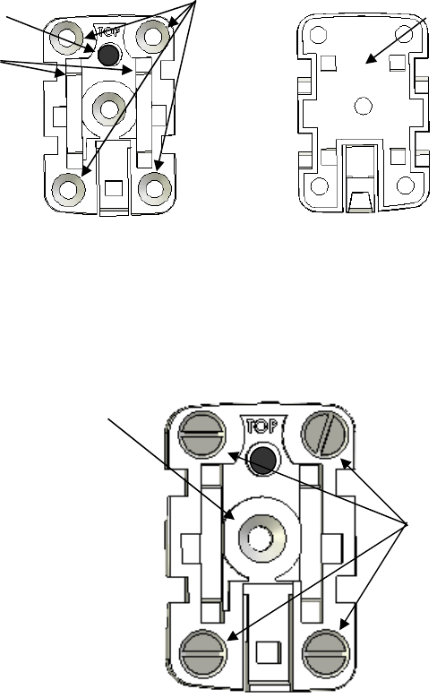
Mounting the SAM
The SAM can be mounted using the included brackets. The
following procedure describes how to attach the brackets
and mount the SAM.
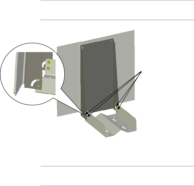
To attach mounting bracket
1 Attach the three mounting brackets to sides and bottom
boss locations on the back of the SAM.
Figure 16: Bosses on the SAM cover.
2 Mount SAM to fixed object (refer to BarMate site survey
for location and object).
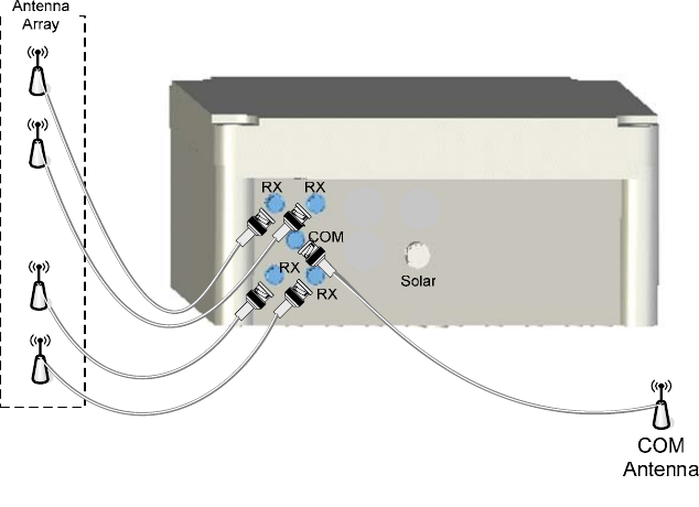
Connecting the Antenna Array, COM Antenna, and
Solar Panel
The antenna array, COM antenna, and solar panel should be
mounted before they are attached to the SAM. The site
survey should indicate the cable lengths needed to connect
the antennas and solar panel to the SAM. The following
procedure describes how to connect the antennas and solar
panel to the SAM.
Back of SAM
Bosses for
mounting
bracket
Chapter 2 Installation
BarMate Installation Guide 31
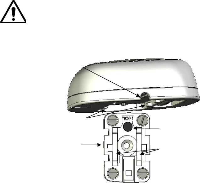
To connect SAM to Antenna Array, COM Antenna, and
Solar Panel
1 For the antenna array, use an RG58 coaxial cable and
connect one end to the SMA port on one of the RX
antennas. Connect the other end to one of the RX
connectors on bottom of the SAM. Repeat this for each
of the four antennas in the array.
2 For the COM antenna, use a coaxial cable and connect
one end to the N-Female connector on the COM
antenna. Connect the other end to the COM (TNC) port
on bottom of the SAM. The TNC port is located in the
middle of the four RX ports.
Figure 17: Antenna connections on the bottom of the SAM.
Chapter 2 Installation
32 BarMate Installation Guide
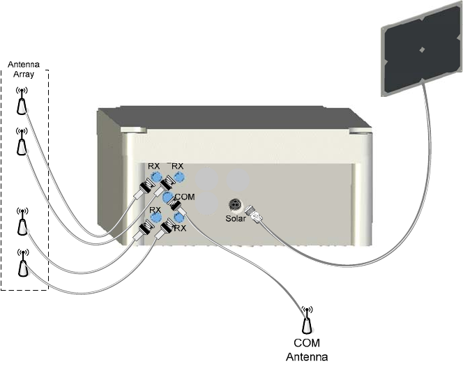
3 Connect one end of the solar panel cable to the Mini-
Con-X Solar port on the SAM. The other end of the cable
is attached to the solar panel. The SAM is now fully
powered.
Figure 18: Antenna and solar panel connections on SAM.
4 The SAM must be configured before it can function. See
“Configuring the SAM” on page 4.
Chapter 2 Installation
BarMate Installation Guide 33
Installing SRDs
The SRD contains an internal battery that is magnetically
activated when the SRD is attached to the Bracket Mount.
The internal SRD battery is not replaceable. To protect
internal electronics, the SRD case is hermetically sealed.
CAUTION:
Trying to open the SRD case will likely break the device,
and the device will no longer be water resistant.
SRD orientation
The SRD includes an internal antenna, which must be in a
vertical position when the SRD is mounted to a surface. The
SRD must also be oriented so that the LED is located on top
so that servers are able to quickly identify a service request.
See Figure 19.
Figure 19: Orientation of SRD when installed.
SRD attachments
The SRD can be mounted to a surface using an adhesive,
screws, or zip ties, or a combination of these attachments.
SRD attached
to side of
lounge chair
so internal
antenna is
vertical
LED is located
on top
Chapter 2 Installation
34 BarMate Installation Guide
To install and mount the SRD
1 Identify a mounting surface that allows the SRD to be
mounted in a vertical orientation.
Figure 20: SRD and mounting plate.
2 Attach to surface identified in site survey:
• If an adhesive is used, attach adhesive to bottom of SRD
Mounting Bracket.
• If Tie-Wraps are used, wrap SRD mounting plate with tie
wrap, inserting tie wrap through plate glides.
• If attaching SRD to a round pole, insert screw to screw
hole in middle of SRD mounting bracket. The screw will
prevent the SRD from rotating around the pole.
► Note: If the adhesive is used for attachment, verify the
surface is clean and dry.
SRD mounting
bracket orientation.
The SRD attaches to
bracket with the LED
on top, so that the
internal antenna is
vertical.
LED is on top
Chapter 2 Installation
BarMate Installation Guide 35
Figure 21: SRD mounting bracket.
3 Attach the SRD Mounting Bracket to a surface using
screws.
Figure 22: SRD mounting bracket and screws.
Sunken
Screw
Slots
Tie-Wrap
Glides
Mounting Bracket - Top
Magnet Adhesive
attaches to
bottom Mounting
Bracket if used
Mounting Bracket – Back
Screws in
sunken holes
secure bracket
to surface at
top of Mounting
bracket
Additional screw
will keep SRD
from rotating
when attached to
a round pole
Chapter 2 Installation
36 BarMate Installation Guide
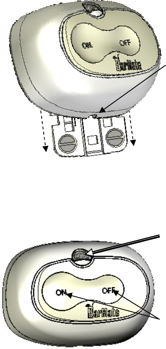
4 Place the SRD on mounted bracket; observe orientation
of SRD and mounting bracket.
CAUTION:
Snapping an SRD into its mounting bracket powers on
the device. Before powering the SRDs, the SAM must be
calibrated with one SRD. After calibrating the SAM, then
snap all SRDs into their brackets. Calibration is an open
question at the moment – TBC!!!
Figure 23: Connecting the SRD to its mounting bracket.
Magnet at top of
bracket
Glides – for tie
wraps
Disconnect Slot
Extenders
fit in
bracket
Bracket
Mount
Chapter 2 Installation
BarMate Installation Guide 37
5 Slide SRD extenders on glides until they snap in place,
locking the SRD to the mounting bracket.
Figure 24: Sliding the SRD onto the mounting bracket.
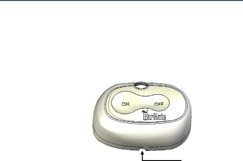
6 To verify that the battery is activated; press the ON
button. The LED flashes indicating the battery is active.
To turn off the LED, press the OFF button.
Figure 25: Mounted SRD.
Slide
Disconnect Slot
on bottom of
SRD
Slide
ON/OFF
butt
o
n
s
LED
Chapter 2 Installation
38 BarMate Installation Guide
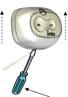
Disconnecting an SRD from a Bracket Mount
Removing an SRD from its Bracket Mount for remounting or
replacement is easy using proper tools.
A slotted screwdriver with a 1/8” tip.
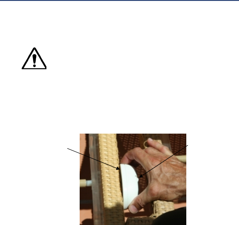
To remove an SRD from its Bracket Mount
1 Insert the screwdriver into the Disconnect Slot on the
side of the SRD.
Figure 26: Disconnect slot on the SRD.
2 Insert screwdriver and apply slight forward pressure
towards the SRD with the screwdriver, while sliding the
SRD upward.
Disconnect Slot
Chapter 2 Installation
BarMate Installation Guide 39
Figure 27: Disconnecting an SRD.
Slide screwdriver up
then gently lever
forwards
Slide
SRD
upward
Chapter 2 Installation
40 BarMate Installation Guide
Chapter 3 Management Centre Setup and Operations
BarMate Installation Guide 41
Chapter 3 Management Centre
Setup and Operations
The purpose of this section is to provide a basic description
of the BarMate Management Centre including how it
operates and how to set it up. Topics discussed in this
section are as follows:
• Setting up the Management on page 4
• Setting up maps on page 4
o About map files on page 4
o Uploading and configuring maps on page 4
• Configuring the SAM on page 4
o Identifying the SAM in the BarMate software
on page 4
o Configuring an SRD for calibration on page 4
o Calibrating the SAM on page 4
o Reconfiguring the SRD for operation on page
4
• Overview of the Management Centre Application
Interface on page 4
o Map tab on page 4
o Service Requests tab on page 44
Chapter 3 Management Centre Setup and Operations
42 BarMate Installation Guide
o Waiter Config tab on page 4
o MC Config tab on page 4
o SAM Config tab on page 4
o SRD Config on page 4
o Messages tab on page 4
o Settings tab on page 4
Chapter 3 Management Centre Setup and Operations
BarMate Installation Guide 43
Setting up the Management Centre
Configuring a Management Centre can be done when the
system is launched for the first time or any time thereafter.
1 Launch the Management Centre application. See
“Launching the Management Centre Application” on
page 4.
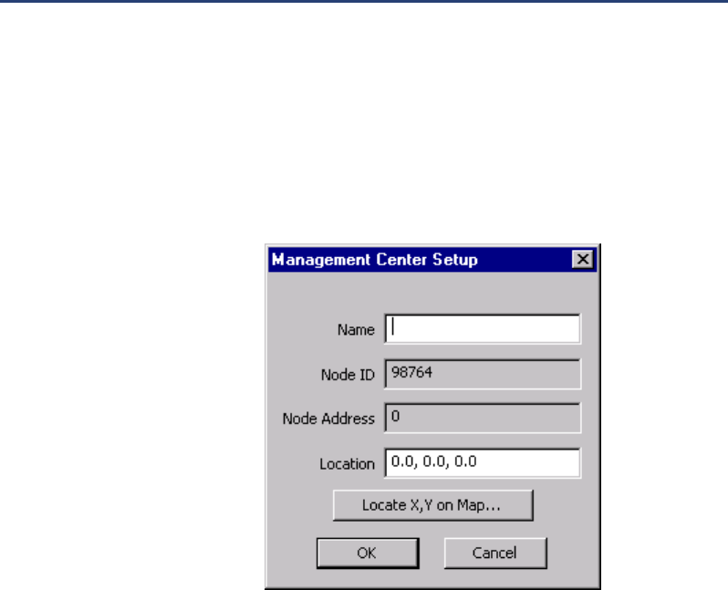
2 Click the MC Config tab and click Edit.
The Management Centre Setup prompt displays.
Figure 28: Management Centre Setup prompt.
3 In the Name box, enter a name for the Master
Management Centre, for example, MMC for Master
Management Centre, and click OK.
A Node ID is automatically assigned. The location for the
Management Centre cannot be entered until maps are
entered into the system. The main Management Centre
work area displays.
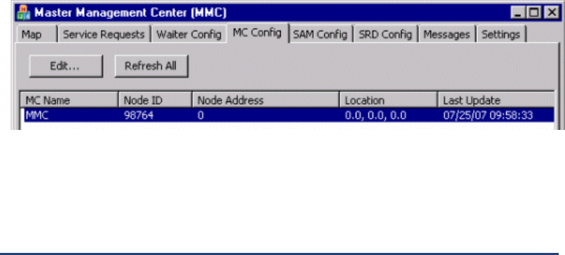
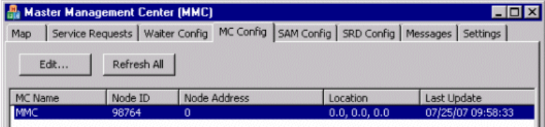
The MC Config tab displays a list of all registered
Management Centres in the system and information
about each system.
Chapter 3 Management Centre Setup and Operations
44 BarMate Installation Guide
The following example shows that one Management
Centre is setup. It shows that the MMC is registered;
however, it is not fully configured as its Node Address
and Location have not been defined.
Figure 29: MC Config tab.
This completes the Management Centre setup. SAMs
may now be connected to power and register into the
system correctly.
Setting up maps
About map files
Map configuration includes uploading a map into the
Management and identifying a Management Centres’ Node
Address and Location. Map file types include .jpeg/jpg, .gif,
.bmp, and .png.
Map files may be stored anywhere on the Master
Management computer. We suggest that maps be stored in
a Maps folder for easy management and browsing.
Uploading and configuring maps
The Management Centre can manage multiple maps. For
example, you may want to include a map of the entire resort
as well as additional maps that provide a close-up of specific
areas.
To configure a map
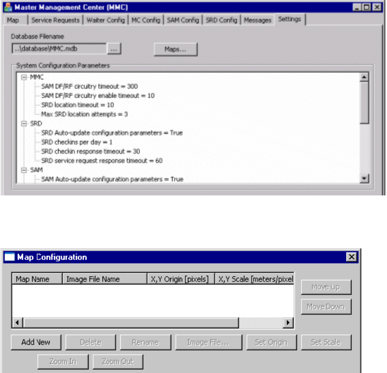
1 Click the Settings tab in the Master Management Centre
(MMC) and the Settings window displays.
Chapter 3 Management Centre Setup and Operations
BarMate Installation Guide 45
Figure 30: Settings tab.
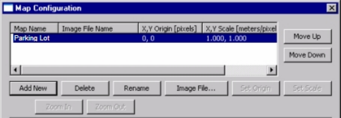
2 Click the Maps... button and the Maps Configuration
window displays.
Figure 31: Map Configuration window.
3 Click Add New, and a prompt asks you to enter a new
map name.
4 Enter a meaningful map name, for example, Parking Lot,
and click OK. The Map Configuration window displays
with the new map entry.
Chapter 3 Management Centre Setup and Operations
46 BarMate Installation Guide
Figure 32: Map Configuration window with new entry.
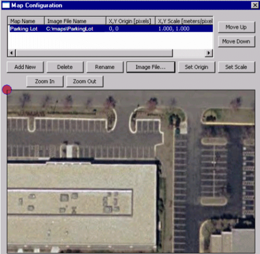
5 Select a Map and click Image File… An Open window
displays.
6 Browse and select the appropriate map, and then click
Open.
The map is now associated with the Map name.
Chapter 3 Management Centre Setup and Operations
BarMate Installation Guide 47
7 Select a map and it displays in the Map Configuration
window. The following example, illustrates a parking lot
map.
Figure 33: Map Configuration window showing selected
map.
8 Set the location and scale of the origin.
a. Use the mouse to pan the image until you see
the origin location (location of Management
Centre) on the map.
b. Click Set Origin. A dialog prompts you to select
a point on the map to identify the system origin
(location coordinates).
c. Click OK, and then click the Origin location on
the map.

Chapter 3 Management Centre Setup and Operations
48 BarMate Installation Guide
A red dot appears on the map (where you clicked)
indicating the Origin, the location of the Management
Centre.
Figure 34: Map Configuration window showing origin
location.
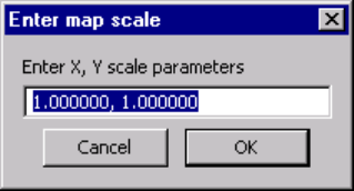
d. Click Set Scale.
e. Specify the scale in meters per pixel for
coordinates X and Y, be sure to separate each
coordinate with a comma, and then click OK.
Chapter 3 Management Centre Setup and Operations
BarMate Installation Guide 49
The following example shows a scale of 1 pixel per
meter for coordinates X and Y. Notice coordinates are
separated by a comma (,).
Figure 35: Enter map scale window.
9 The Map is now configured.
If multiple maps are configured in the system, the map at
the top of the list will always display when the
Management Centre is launched.
10 Select a map and click Move Up or Move Down to
specify the map that will display when the application
launches.
11 Click X in the upper, right corner to close the window.
Chapter 3 Management Centre Setup and Operations
50 BarMate Installation Guide
12 Click the Map tab. The Map tab also displays when the
Management Centre is launched and will display the
primary map.
Figure 36: Master Management Centre window showing
primary map.
Maps are now uploaded into the Management Centre.
Parking Lot

Chapter 3 Management Centre Setup and Operations
BarMate Installation Guide 51
Configuring the SAM
After the SAM and SRDs have been mounted, the SAM
must be configured to be fully operational. To configure the
SAM the following tasks must be completed:
1 Identify the SAM in the BarMate software
2 Configure an SRD to calibrate the SAM
3 Calibrate SAM
4 Reconfigure the SRD for operation
Each task is described in the following sections.
► Note: Each time a SAM is powered on, a dialog will display
in the Management Centre prompting you to configure the
SAM now or later.
Identifying the SAM in the BarMate software
For the SAM to be operational, you must identify the device
on the map in the BarMate software.
To identify the SAM
1 Click the SAM Config tab, and then select and edit the
desired Node ID.
2 Next, you’ll need to locate the SAMs XY coordinates.
This button displays a map enabling you to click on the
map using the mouse to identify its location. The XY
coordinates are automatically calculated by the system.
Configuring an SRD for calibration
An SRD must be configured to the radio frequency (RF)
appropriate for calibrating the SAM.
To configure an SRD for calibration
1 Click the Settings tab, and then select SRD service
request response timeout.

Chapter 3 Management Centre Setup and Operations
52 BarMate Installation Guide
2 Change the SRD service request response timeout
value to 0 (zero). The default value is 60.
3 Click the Message tab, and then select the appropriate
SRD.
4 In the Test Commands group, select SRD RF On.
5 Cycle the SRD’s power.
SRD re-registers with the Management Control Centre.
The SRD is now set to the proper RF for calibrating the
SAM.
6 See “Calibrating the SAM” on page 4.
► Note: After calibration is complete, the RF and SRD
service request response timeout values must be set back
to their original values.
Calibrating the SAM
After configuring an SRD for calibration, you can calibrate
the SAM. Calibrating the SAM is a two-person task in which
one installer trains the SAM using a transmitting SRD.
Another installer collects calibration data points at the Master
Management Centre (MMC).
To Calibrate a SAM
As an installer with the transmitting SRD moves around the
circumference of the SAM, the installer will stop at specific
increments (for example, every 20 meters) and the SRD will
automatically send a signal to the SAM. SAM collects the
data points to learn the SRD’s position.
Calibration data is collected at the MMC after identifying the
SAM Node ID. By specifying the Polar Coordinates (Angle
and Distance), each time a data point is identified (a signal
received from the transmitting SRD), you collect the
calibration data. After collecting the calibration data, you
clear one of the coordinates, usually the Y box, so that you
can collect another data point. The installer with the SRD
then moves, maintaining a fixed radial distance from the
SRD, and stops so that the MMC can collect another
calibration data point. This process is repeated until each
Chapter 3 Management Centre Setup and Operations
BarMate Installation Guide 53
data point around the SAM is collected. This process is also
repeated for the location of each SRD.
If there is no response after collecting a data point (an
inactive data point textbox) or if a message, “Timeout
Occurred,” displays, simply re-enter the coordinates. In
some cases, the installer with the SRD may also need to
adjust their position so that the SAM is able to capture the
coordinates.
After completing the circumference, calculate and save the
parameters. This saves and updates the database with the
SAM calibration.
Reconfiguring the SRD for operation
After the SAM is calibrated, the SRD’s parameters must be
reset back to their original values.
To reconfigure the SRD for operation
1 Click the Settings tab, and then select SRD service
request response timeout.
2 Change the SRD service request response timeout
value to 60.
3 Click the Message tab, and then select the appropriate
SRD.
4 In the Test Commands group, select SRD RF Off.
5 Cycle the SRD’s power.
SRD re-registers with the Management Control Centre.
The SRD is now set to the proper RF to operate in the
BarMate system.

Chapter 3 Management Centre Setup and Operations
54 BarMate Installation Guide
Overview of the Management Centre Application Interface
The Master Management Centre manages all elements of
the BarMate system. It manages setup and configuration of
components; adding and updating system components, for
example expanding an existing system to add new maps,
Management Centres, SAMs, and SRDs. It also manages
day-to-day operations.
When the application is launched the Map tab displays and
the primary map displays in the Map window.
The following sections describe the functionality that each
tab provides and the primary user of those functions.
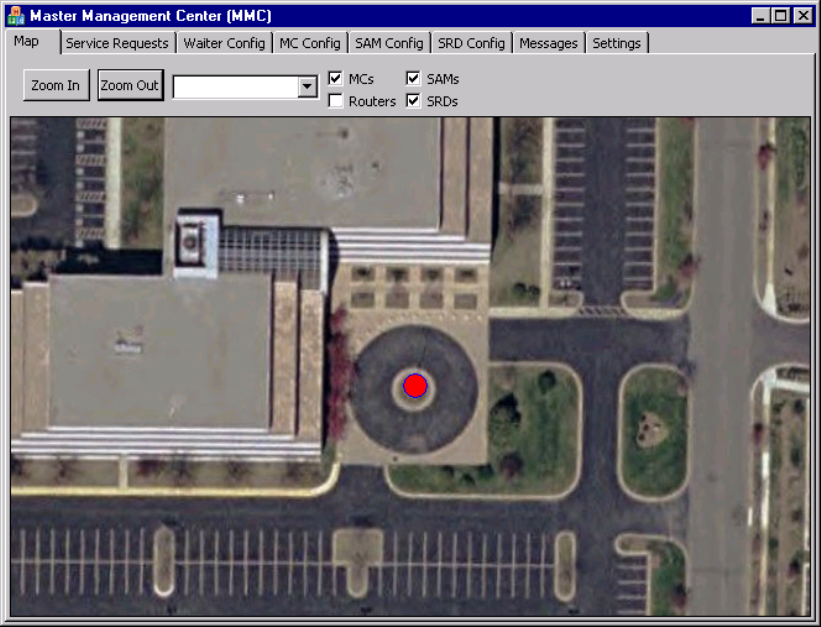
Map tab
This tab displays a map of the service area (see Figure 37
on page 4) and can identify the location of BarMate
components. The text box identifies which map displays in
the Map window. (Multiple service area maps may be
installed on a system to provide clear resolution of a service
area.) The arrow is a pull-down menu that lists service area
map selections. The check boxes display the location of
BarMate components — MCs, SAMs, and SRDs (routers are
not currently used). The primary users of this tab are
Administrators and Waiters to locate components,
specifically the location of SRDs (guests requesting service).
► Note: Identifying a primary map (the map that appears in
the map window when the application is launched) is
performed in the MC Config tab.
Chapter 3 Management Centre Setup and Operations
BarMate Installation Guide 55
Figure 37: Description of Map tab.
To view BarMate components on a resort map
1 Click the text box drop-down menu arrow and select the
desired map to display in the map window.
2 Click the Zoom in or Zoom out buttons for optimal
resolution of the service area map.
3 Click the check boxes to select or deselect components
that display on the map: MCs (Management Centres),
SAMs (Service Area Managers), and SRDs (Service
Request Devices) on the map. Deselecting a check box
will remove it from the service area map displaying in the
map window.
Parking Lot
Chapter 3 Management Centre Setup and Operations
56 BarMate Installation Guide
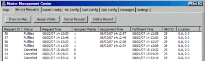
Service Requests tab
This tab manages service requests. Each state of a request
illuminates a different colour to indicate a pending request,
the device location, when the request is assigned, when a
request is satisfied, and when a request is cancelled. The
primary users of this tab are Waiters and Administrative
personnel.
Figure 38: Description of Service Requests tab.
To manage service requests
• Click the Show on Map button to display the location of
the device/guest.
• Click the Assign Waiter button and identify waiter taking
ownership / responding to the service request.
• After attending guest,
o Press OFF on the SRD to clear the server
request.
o Click the Cancel Request button to cancel a
request for service without deleting the record
(service request).
• Click the Delete Record button to delete the database
record of request from the system.

Chapter 3 Management Centre Setup and Operations
BarMate Installation Guide 57
Waiter Config tab
This tab manages waiters: logs waiters who are on duty in
and out, and provides the ability to add or remove waiters to
an MC. The MC that a waiter is logged in on determines the
area to which a waiter is assigned. For example, if a waiter
logs into MC “A”, the waiter is assigned to area “A”. The
primary users of this tab are Administrators.
Figure 39: Description of Waiter Config tab.
To manage waiters
• Select the appropriate name or ID and click Log In to
sign into the BarMate system.
• Select the appropriate name or ID and click Log Out to
sign out of the BarMate system.
• Click the Add New button and enter a new name or ID
to add a new waiter to this MC.
• Select the name or ID to be removed and click Remove
to remove a waiter from this MC.
Chapter 3 Management Centre Setup and Operations
58 BarMate Installation Guide
MC Config tab
Provides a list of all Management Centres (MC) configured
in the system. The window displays the location of MCs;
buttons provide configuration management of MCs.
Figure 40: Description of MC Config tab.
• Edit button allows you to edit and update map
configurations.
• Refresh All” button is useful for Secondary MCs (non
Master). This button clears the local database of all MCs
and creates a new list of all MCs from the Master MC.
This is useful if the Master MC and a Secondary MC are
out of sync.
Chapter 3 Management Centre Setup and Operations
BarMate Installation Guide 59
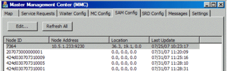
SAM Config tab
This tab provides a list and pertinent information about all
SAMs configured in the system. The window displays the
Node ID, Node Address, Location, and last configuration
update of each SAM in the BarMate system. Buttons provide
configuration management of individual SAMs. The primary
users of this tab are BarMate Installers and BarMate Service
personnel.
Figure 41: Description of SAM Config tab.
• Edit button – allows you to edit and update a specific
SAM configuration.
• Refresh All button – useful for clearing and updating the
local database of all SAMs. It will create a fresh, new list
of all SAMs in the system. This is useful if the Master
MC and a Secondary MC are out of sync.
Chapter 3 Management Centre Setup and Operations
60 BarMate Installation Guide
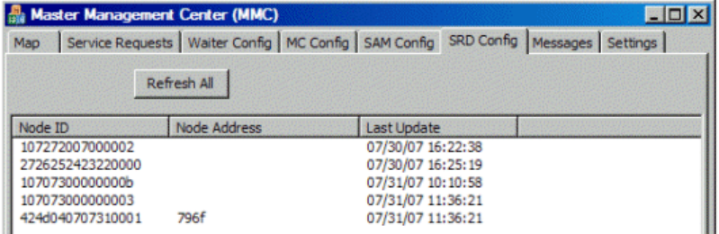
SRD Config
This tab provides a list of all SRDs in the system. The
window displays the Node ID, Node Address, and the date
last SRD registered into the BarMate system. The primary
users of this tab are BarMate Installers and BarMate Service
personnel.
Figure 42: SRD Config tab description.
The Refresh All button – clears and updates the local
database of all SRDs. It will also create a fresh, new list of
SRDs in the system. This is useful if the Master MC and a
Secondary MC are out of sync.
Chapter 3 Management Centre Setup and Operations
BarMate Installation Guide 61
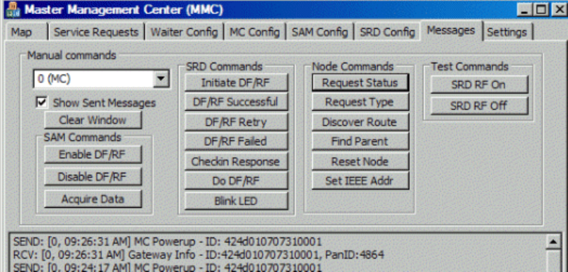
Messages tab
This tab is used for troubleshooting purposes. The Message
window provides internal status and troubleshooting
information exchanged between a Gateway and MC. The
primary users of this tab are BarMate Installers and BarMate
Service personnel.
Figure 43: Description of Messages tab.
Chapter 3 Management Centre Setup and Operations
62 BarMate Installation Guide
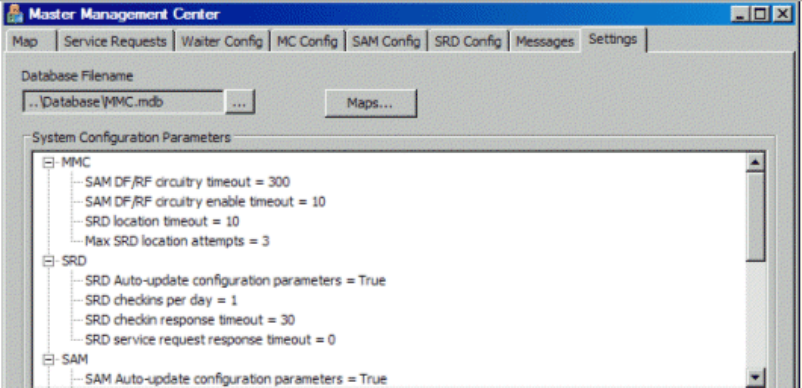
Settings tab
This tab provides the ability to add and configure new maps
to the system and to configure various parameters related to
system operation. The primary users of this tab are BarMate
Installers and BarMate Service personnel.
Figure 44: Description of Settings tab.
Appendix A BarMate Site Survey Example
BarMate Installation Guide 63
Appendix A BarMate Site
Survey Example
This appendix provides an example BarMate site survey that
is used to support installation. This appendix is for reference
purposes only.
Appendix A BarMate Site Survey Example
64 BarMate Installation Guide
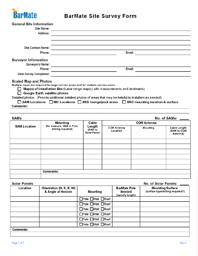
Figure 45: Site Survey Example, page 1.
Appendix A BarMate Site Survey Example
BarMate Installation Guide 65
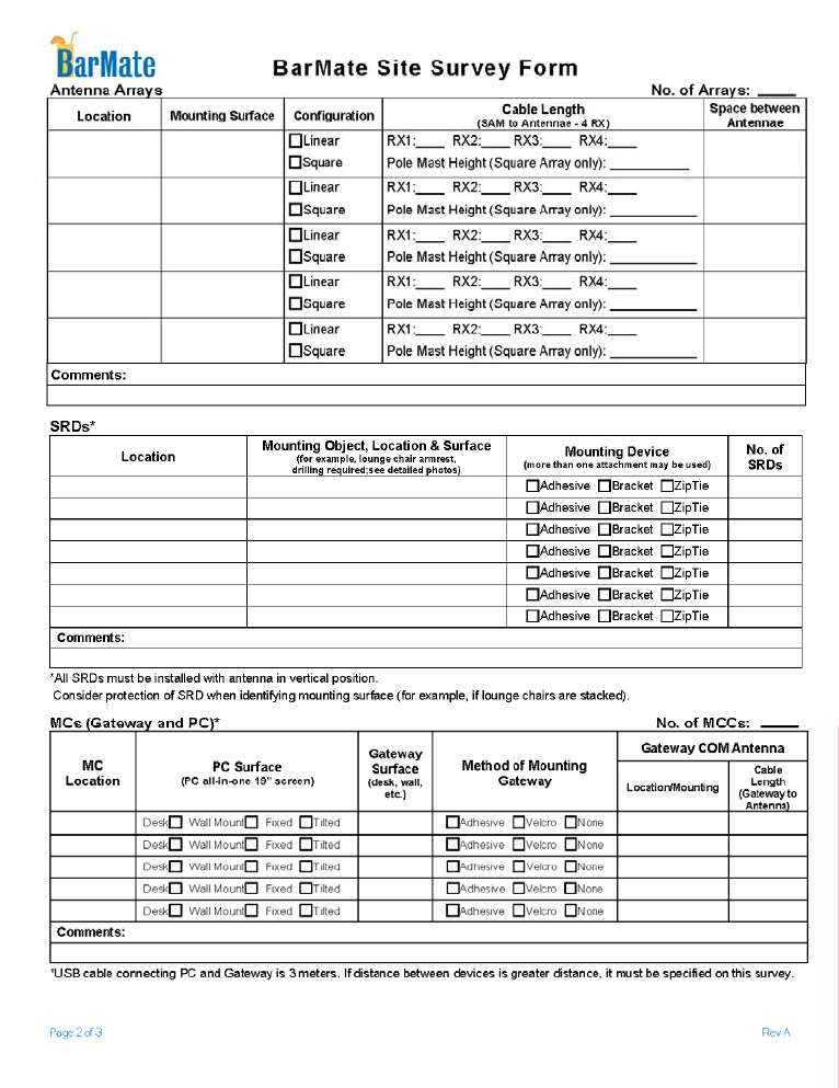
Figure 46: Site Survey Example, page 2.
Appendix A BarMate Site Survey Example
66 BarMate Installation Guide
Figure 47: Site Survey Example, page 3.
Appendix B: Square Array Drawing Specification
BarMate Installation Guide 67
Appendix B: Square Array
Drawing Specification
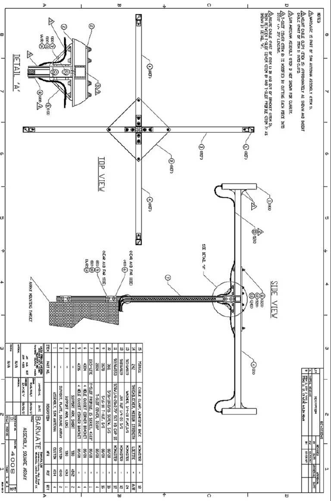
This section provides a Drawing Specification that illustrates
construction of a Square Array.
Appendix B: Square Array Drawing Specification
68 BarMate Installation Guide
Acronyms
BarMate Installation Guide 69
Acronyms
CE – Conformité Européenne (European Conformity)
COAX – Coaxial Cable
FCC – Federal Communications Commission
LED – Light Emitted Device
MC – Management Centre
MMC – Master Management Centre
NEMA – National Electrical Manufacturers Association
PC – Personal Computer
SAM – Service Area Manager
SRD – Service Request Device
TX – Transmit
RX – Receive
USB – Universal Serial Bus
Acronyms
70 BarMate Installation Guide

BarMate Ltd ▪ Trafalgar House ▪ Grenville Place ▪ London ▪ NW7 3SA ▪ UK
Copyright BarMate 2008 ▪ Printed March 2008 ▪ Revision A