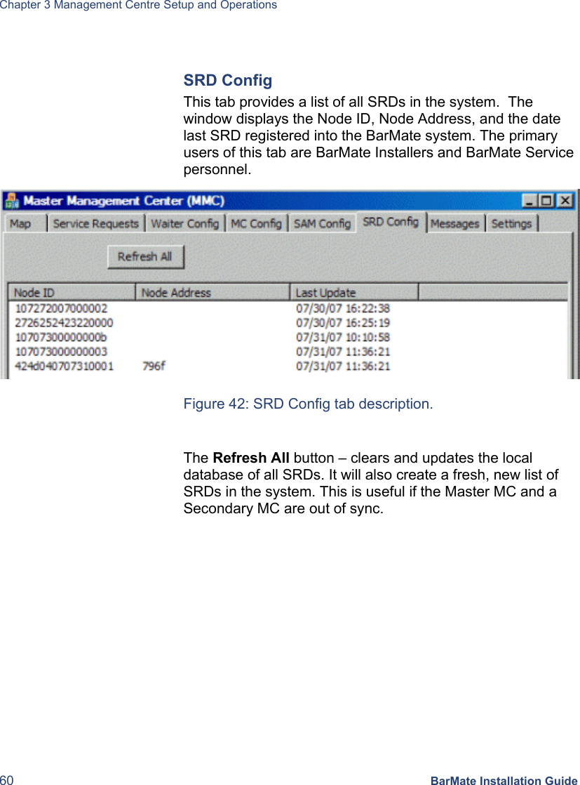
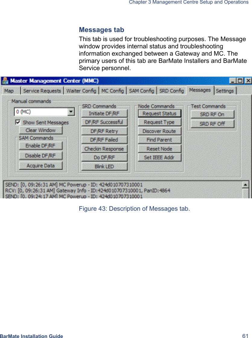
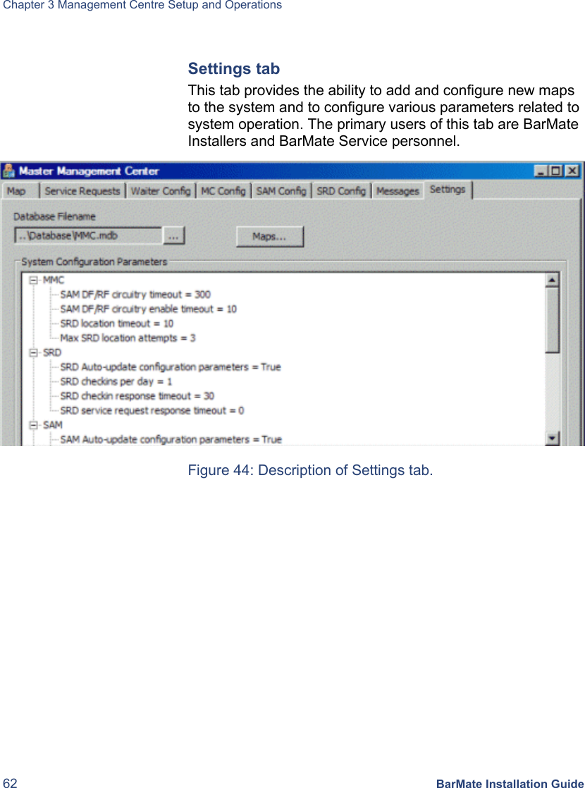
BarMate BARMATE-SAM BARMATE SYSTEM - SAM User Manual BarMate Installation Guide
BarMate Limited BARMATE SYSTEM - SAM BarMate Installation Guide
BarMate >
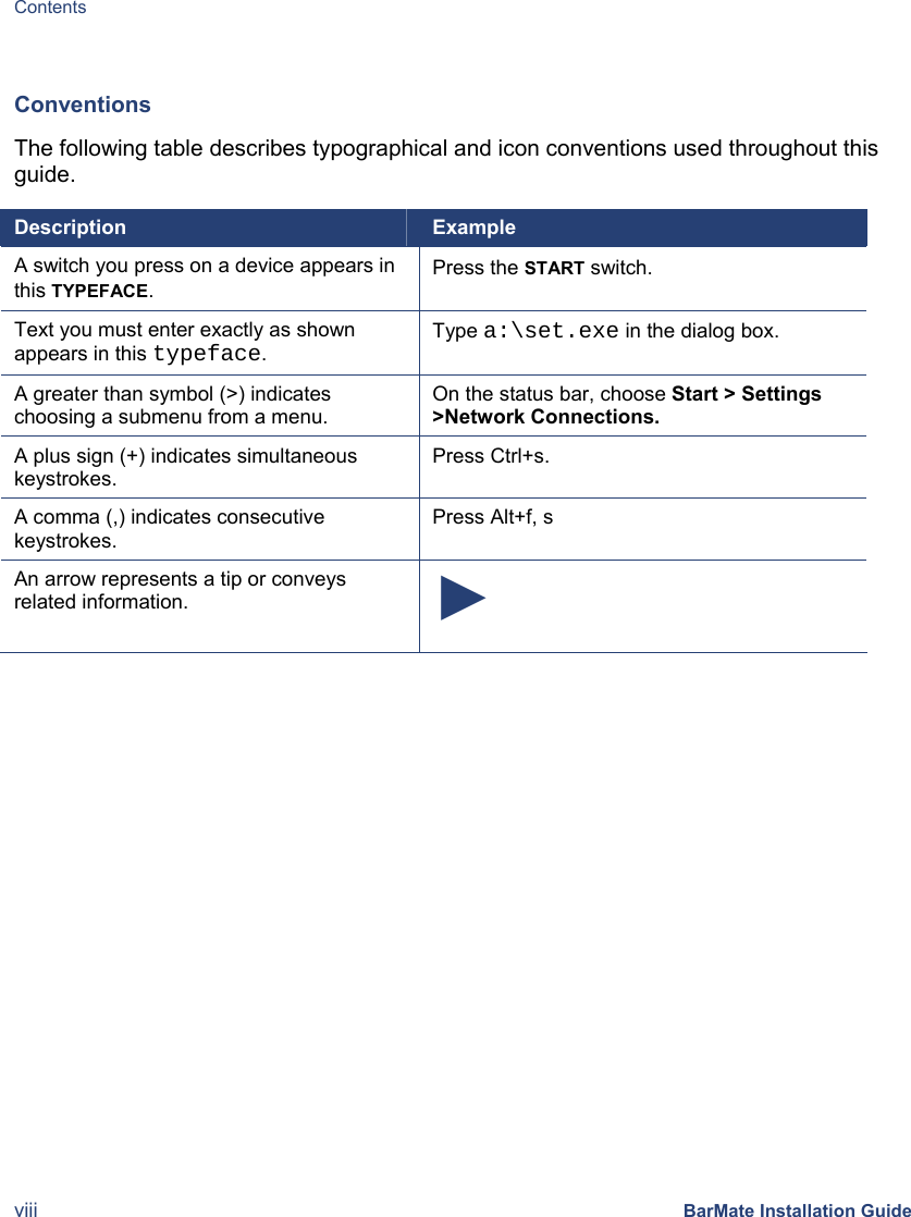
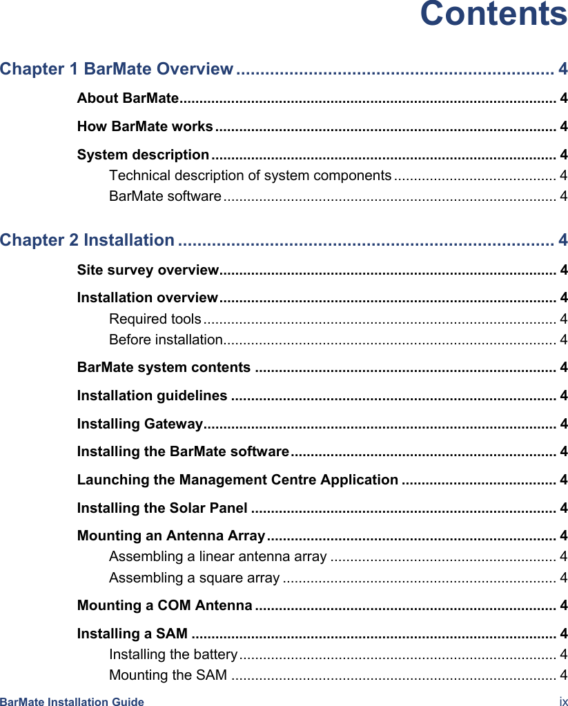
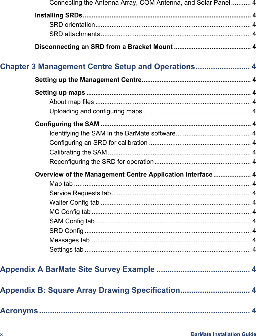
Contents
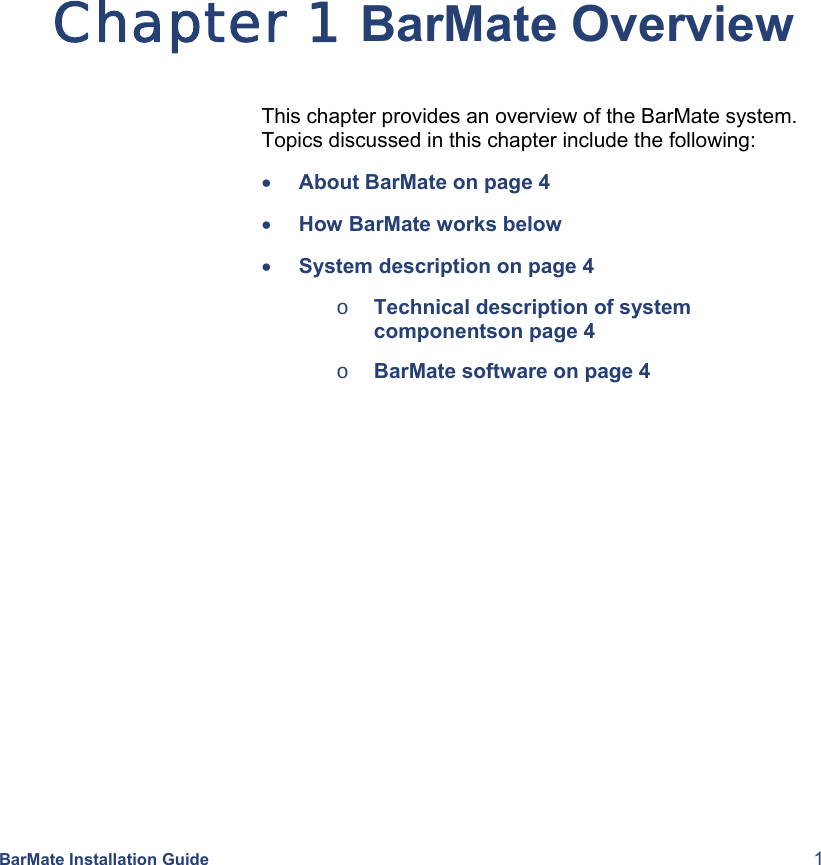
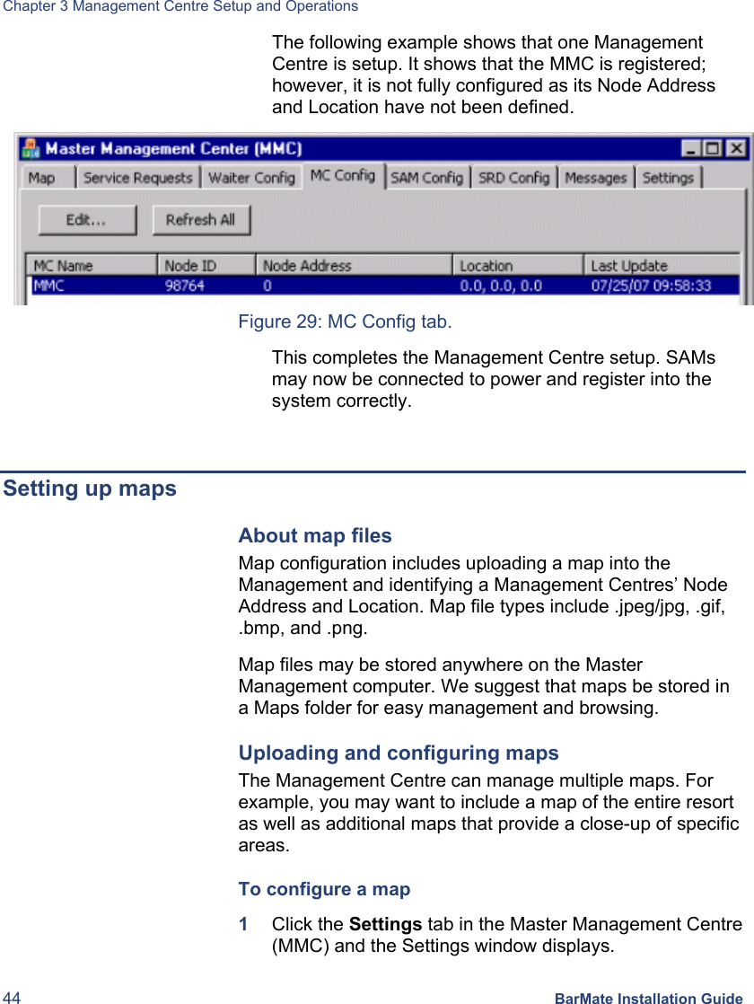
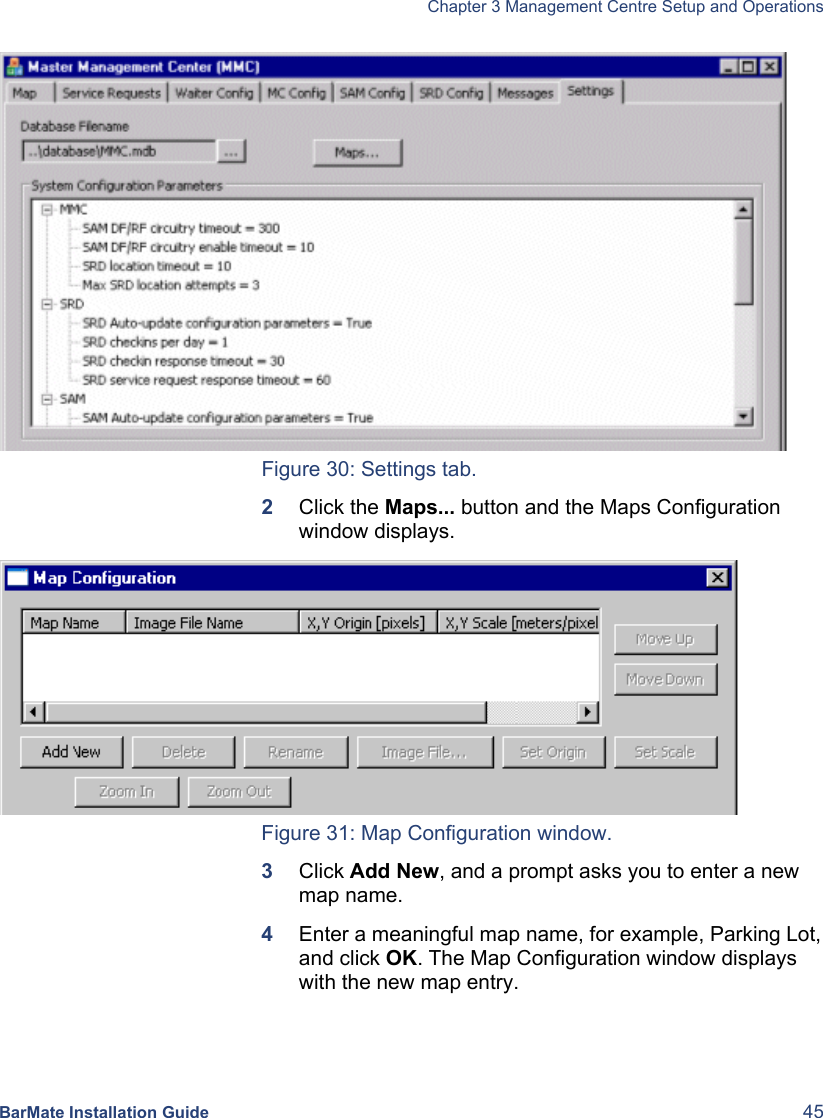
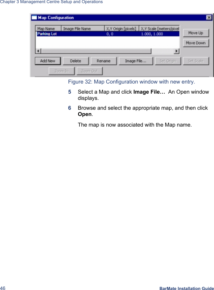
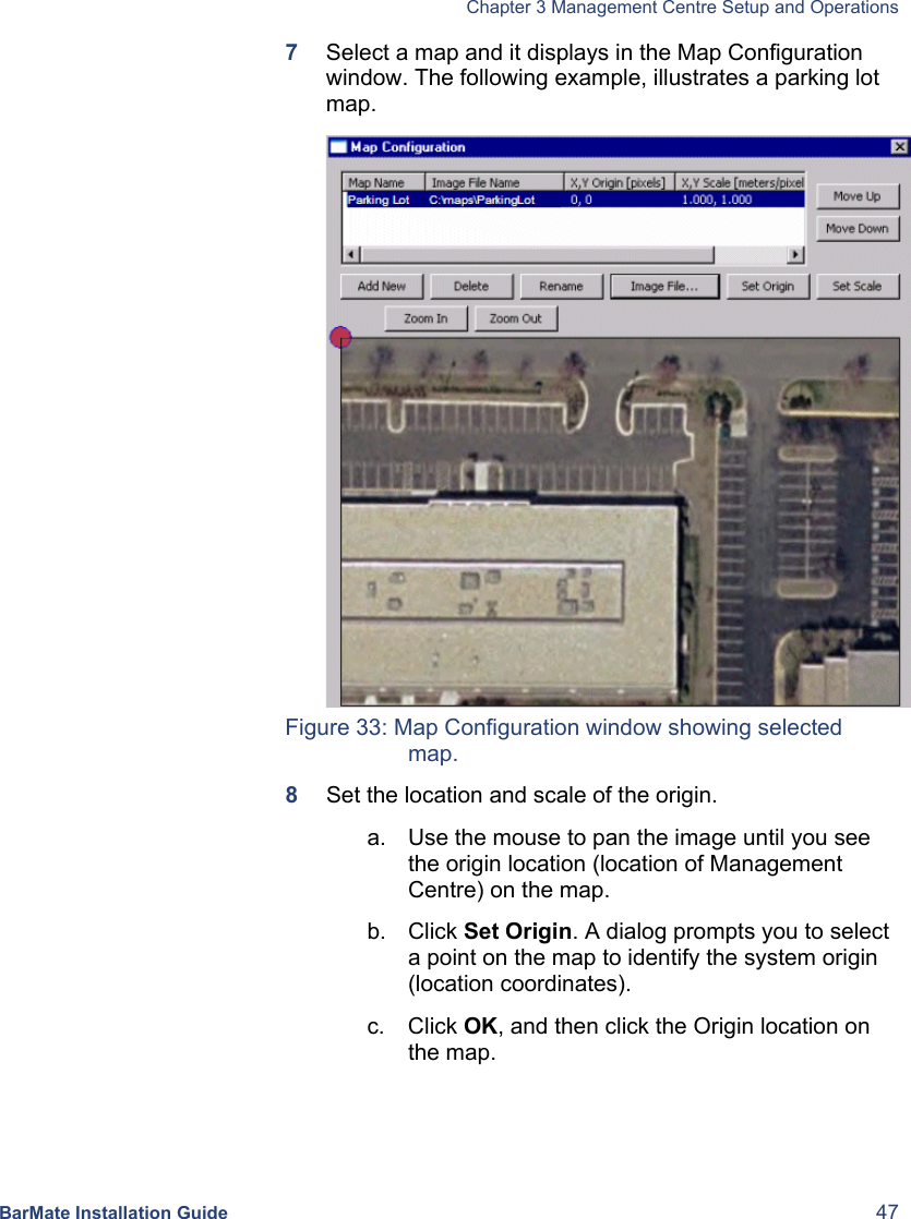
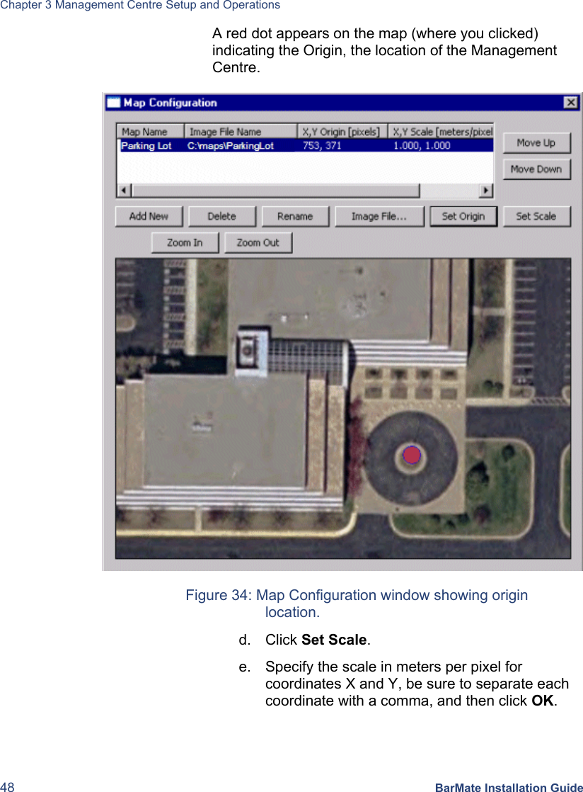
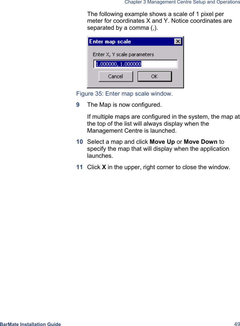
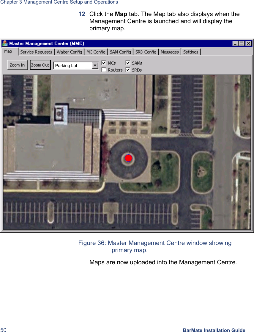
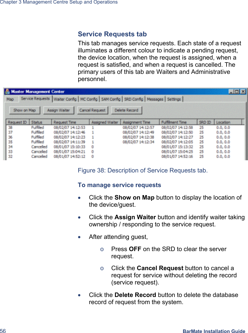
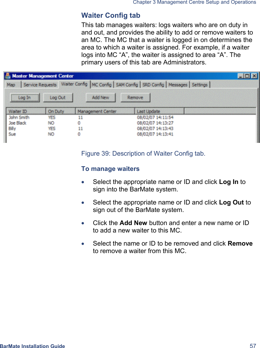
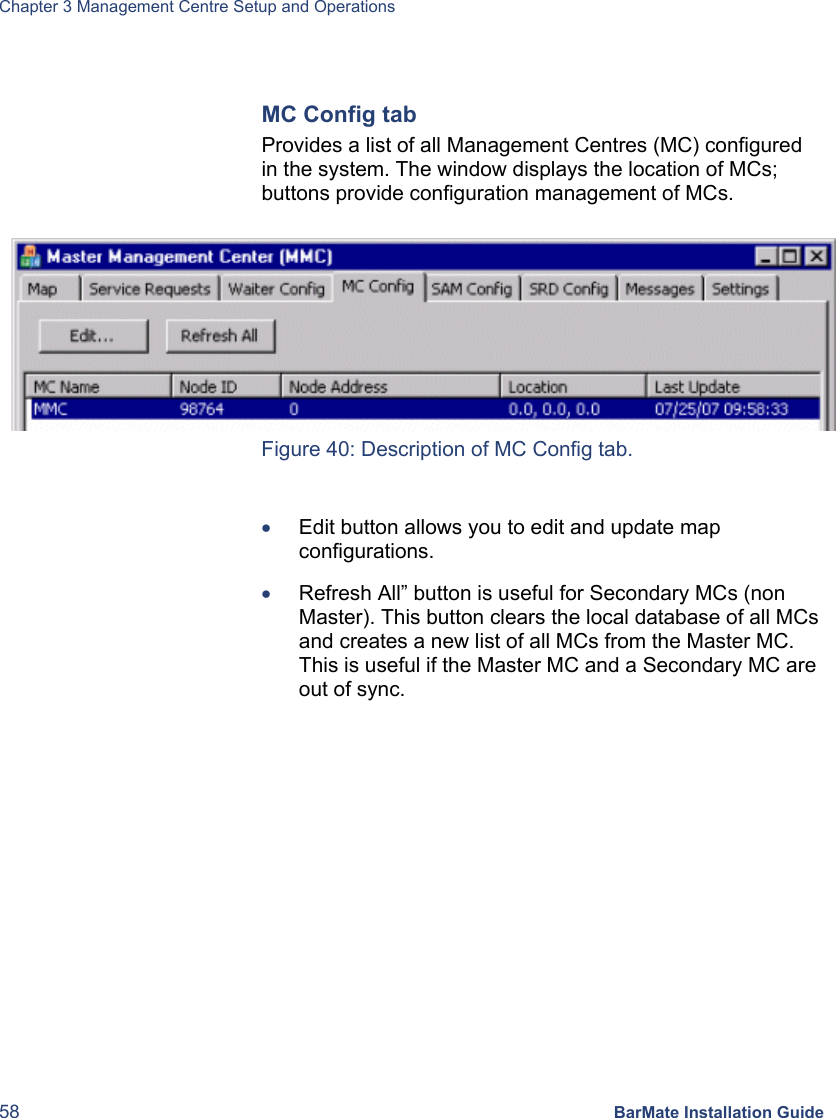
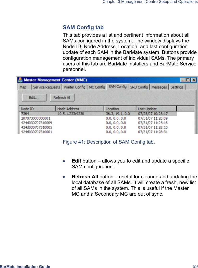
- 1. BarMate Installation Guide
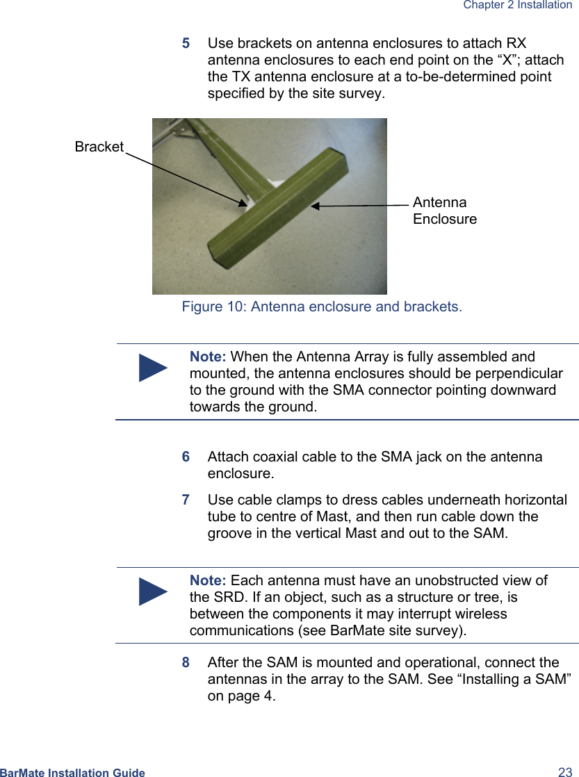
- 2. BarMate User Manual
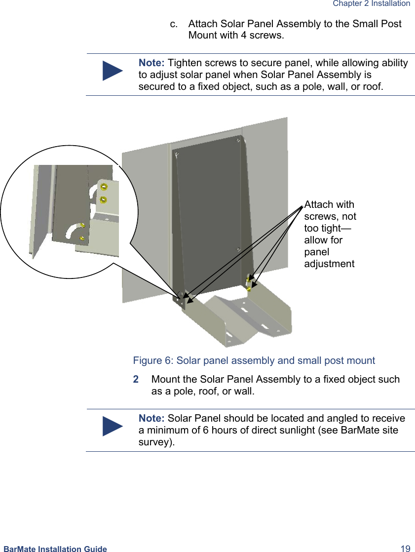
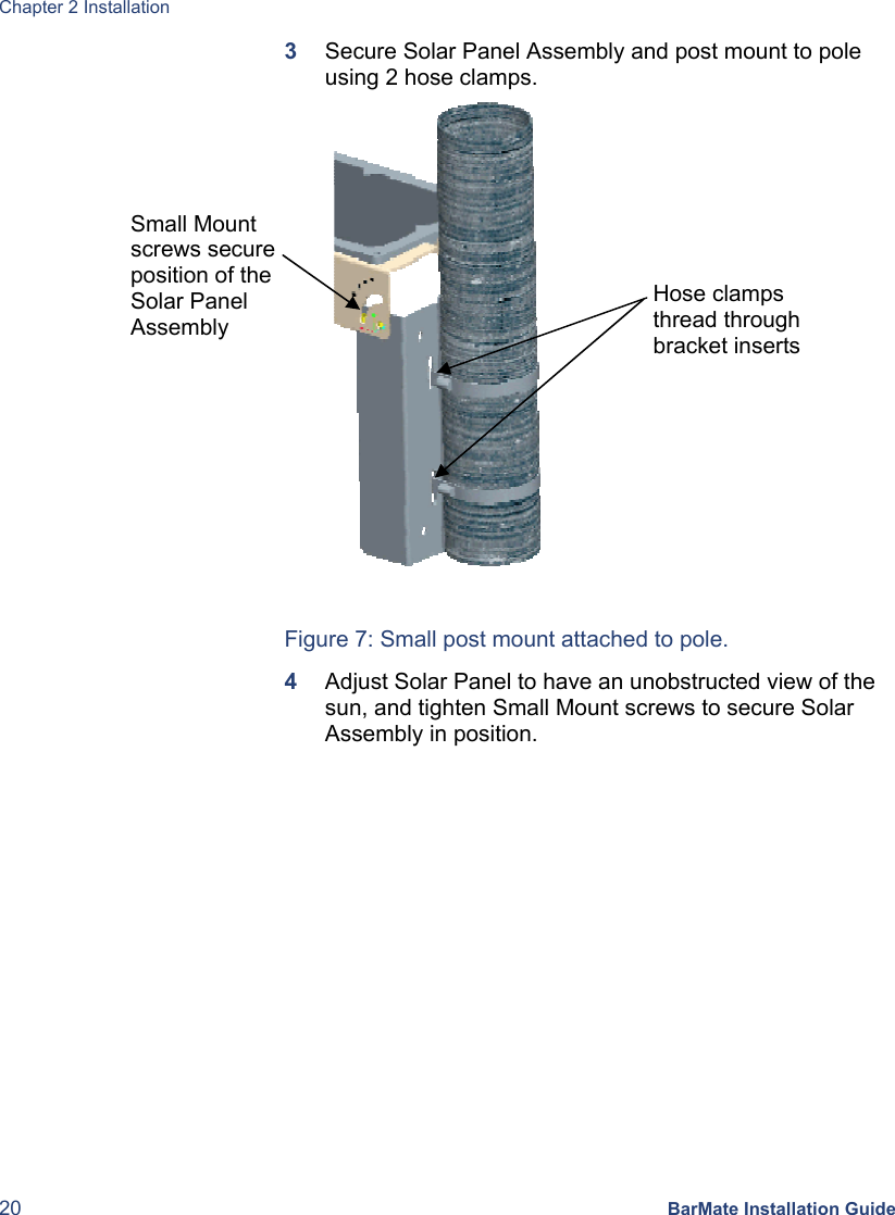
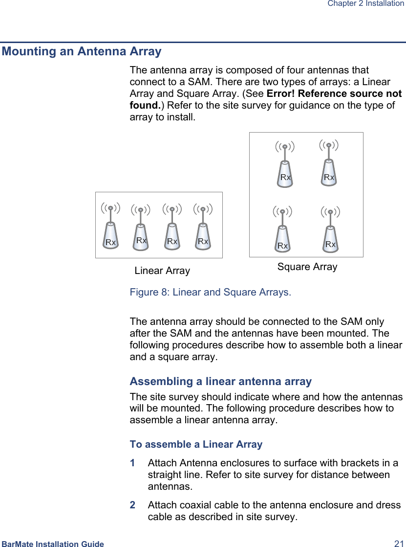
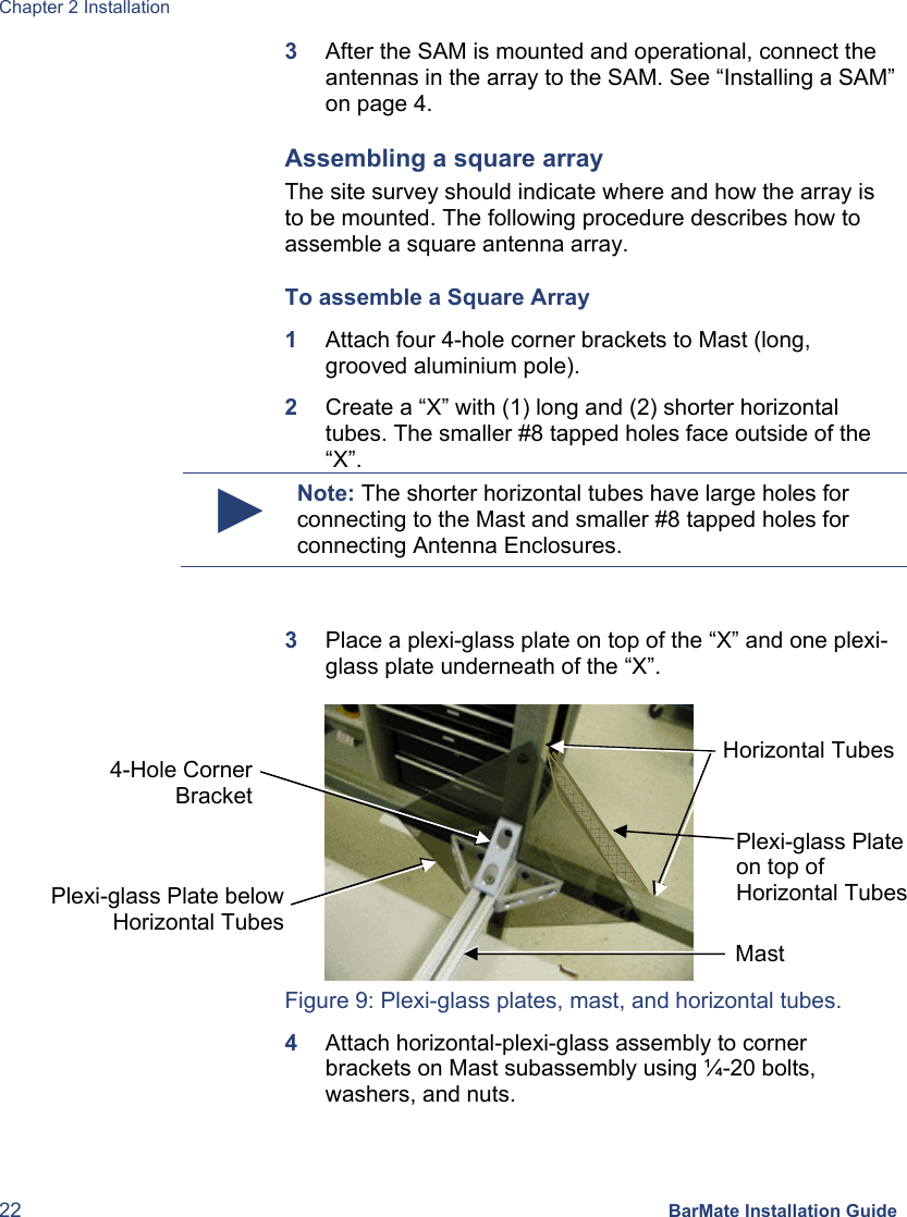
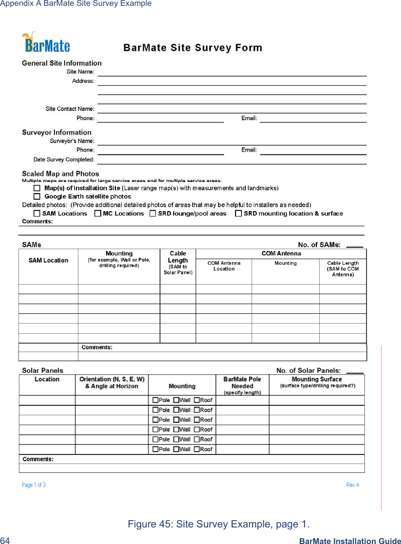
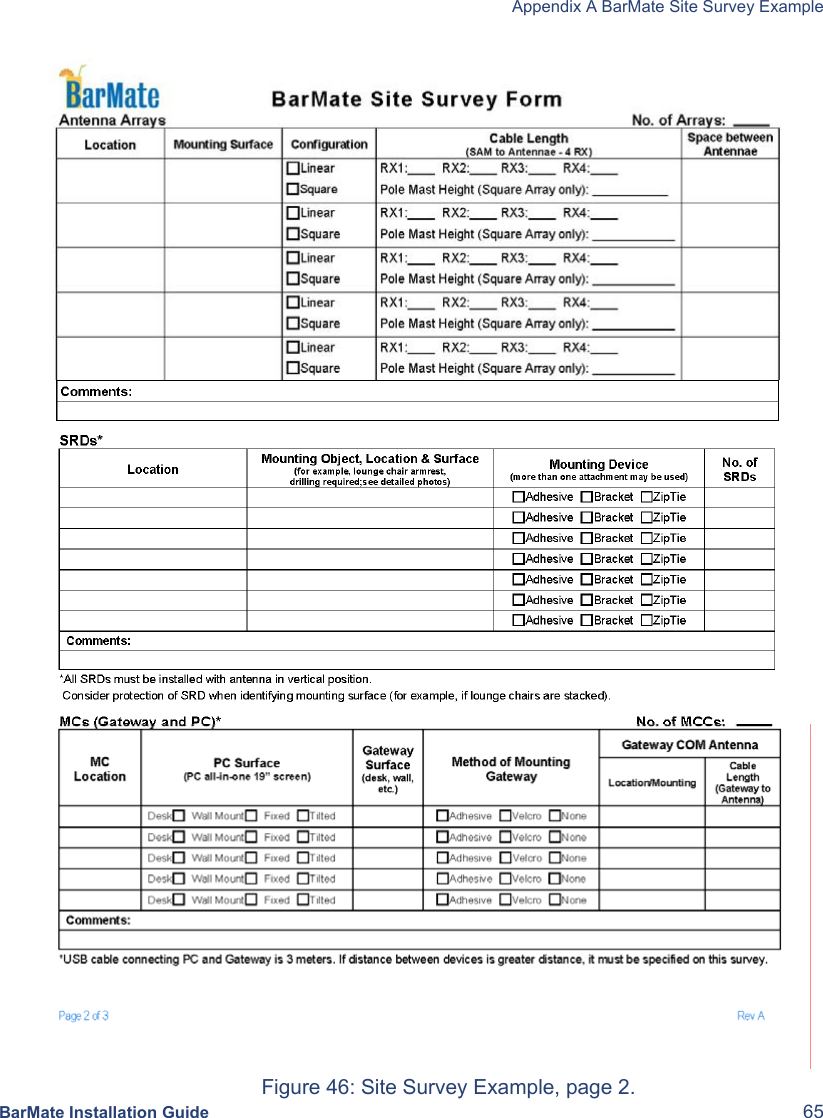
BarMate Installation Guide