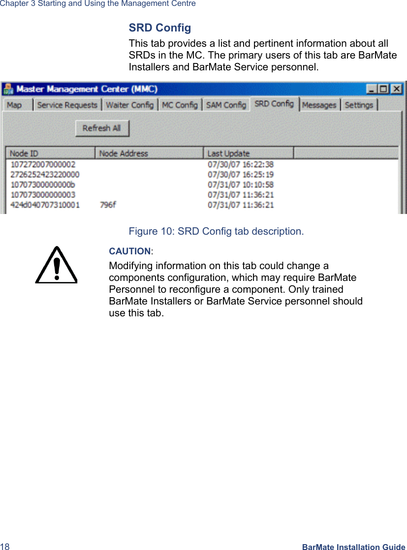
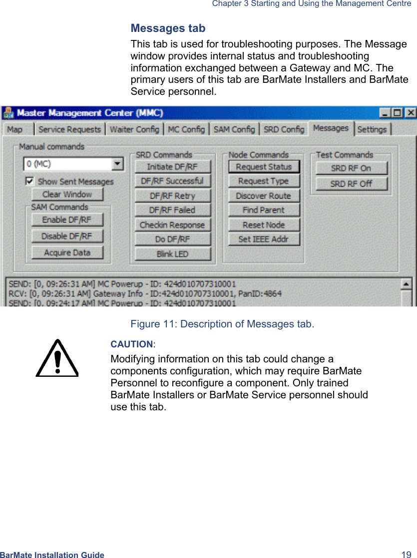
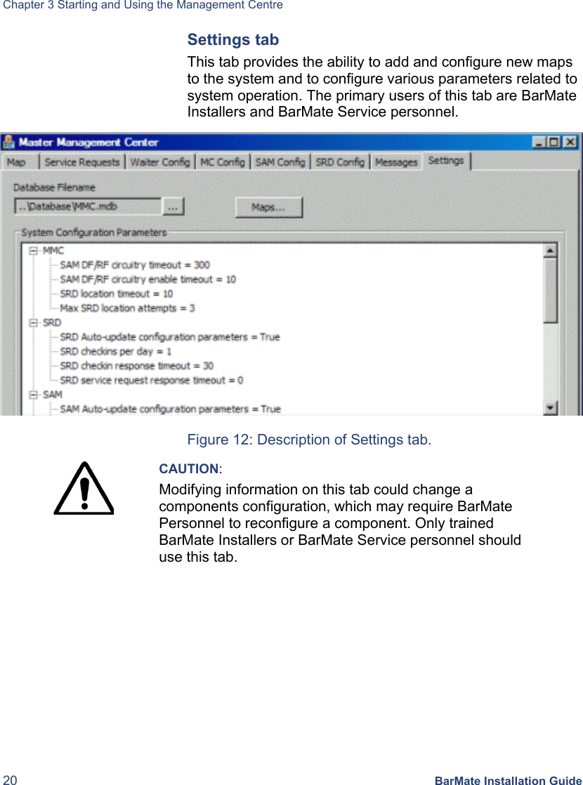
BarMate BARMATE-SAM BARMATE SYSTEM - SAM User Manual BarMateUsersGuideRevA3
BarMate Limited BARMATE SYSTEM - SAM BarMateUsersGuideRevA3
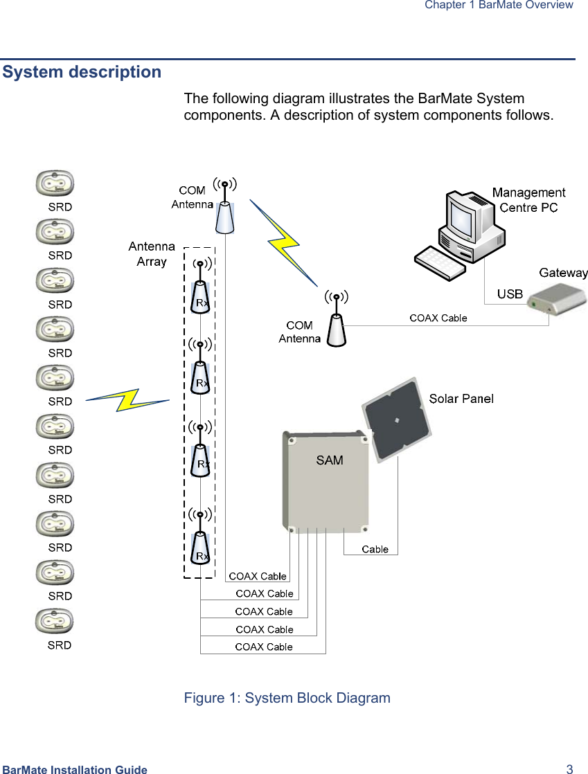
UserManual.wiki
>
BarMate
>
BARMATE-SAM User Manual
>
BarMate User Manual
Contents
1.
BarMate Installation Guide
2.
BarMate User Manual
BarMate User Manual
Navigation menu
Upload a User Manual
Namespaces
Wiki Guide
HTML
PDF
Info
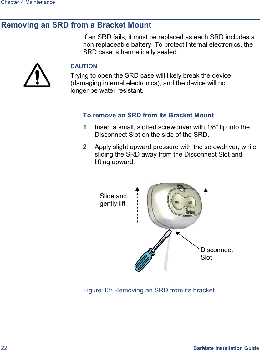
Views
User Manual
Discussion / Help
Navigation