Barco N V J150A01 Panel PC User Manual
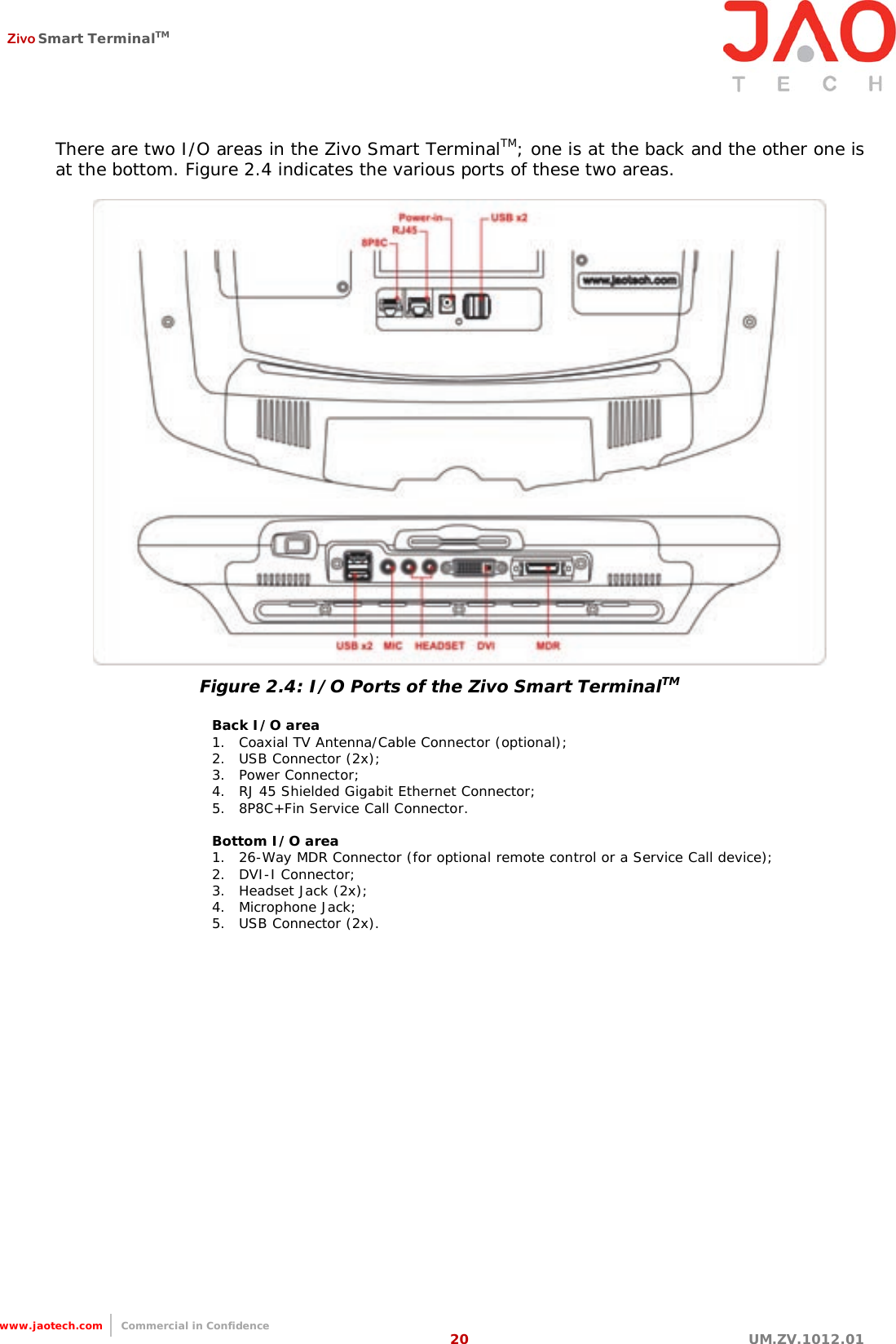
Barco N.V. Panel PC

User manual

          Zivo Smart TerminalTM  User Manual UM.ZV.1012.01    Revision 1 October 09, 2012 JAOtech Ltd
 Zivo Smart TerminalTM   1 UM.ZV.1012.01                                                                  www.jaotech.com     Commercial in Confidence Contents  Revisions & amendment record      4    Introduction 0.1 Copyright     5 0.2  Disclaimer        5 0.3  Life support policy       5 0.4  Acknowledgements       6 0.5  FCC interference statement class B       7 0.6  JAOtech customer services     7 0.7  Technical support     7 0.8  Product warranty       8 0.9  Safety instructions     9 0.10  Packing list     11  Chapter 1 General information 1.1  Introduction    12 1.2  Specifications     13 1.2.1  General     13 1.2.2  Handset specifications     15 1.2.3  Camera specifications     15 1.2.4   Other optional peripherals     16 1.3  Cleaning    16 1.4  Dimensions    17  Chapter 2 System setup 2.1  A quick tour of the Zivo    18 2.2  Installation procedures    21 2.2.1  Connecting the power cord    21 2.2.2  Connecting the keyboard and mouse    21 2.2.3  Switching on the power    21 2.3  Running the BIOS setup program    22 2.4  Installing system software    22 2.5  Installing the drivers    22  Chapter 3 Graphic chipset setup 3.1  Introduction    23 3.1.1  Chipset    23 3.1.2  Display memory    23 3.1.3  LVDS transmitter    23 3.1.4  Display types    23 3.2  Installation for Windows XP    23 3.3  Further information    23  Chapter 4 Audio interface 4.1  Introduction    24 4.2   Audio system    24 4.3   Installation of audio driver    24
 Zivo Smart TerminalTM   2 UM.ZV.1012.01                                                                  www.jaotech.com     Commercial in Confidence 4.3.1  Installation for Windows 2000 XP     24 4.4   Further information      25    Chapter 5 Touch screen interface 5.1  Introduction    26 5.1.1  General information    26 5.1.2  General specifications    26 5.1.3  Environmental specifications    26 5.2  Installation of touch screen drivers    27 5.2.1  Installation for Windows    27 5.3  Further information    27
 Zivo Smart TerminalTM   3 UM.ZV.1012.01                                                                  www.jaotech.com     Commercial in Confidence Appendix  Appendix A Mother board layout A.1  Atom with Intel 945GSE    28  Appendix B Jumpers and connectors B.1 Jumpers setting   29 B.2 Connectors    30  Appendix C Hardware installation C.1  Overview of hardware installation and upgrading    36 C.2  Disassembling the terminal   36 C.3  Installing the 2.5" Hard Disk Drive (HDD)    37 C.4  Installing the Central Processing Unit (CPU)    37  Appendix D    VESA mounting    38  Appendix E Desk Stand E.1  Installing the Smart Terminal to the Desk Stand    40 E.2  Safety Instructions    40
 Zivo Smart TerminalTM   4 UM.ZV.1012.01                                                                  www.jaotech.com     Commercial in Confidence Revisions & Amendment Record  Issue No. Date Section Reason A July 20, 2010  First draft B Feb 18, 2011  • Remove Core Duo and 945GME specifications • Remove COM1 spec. • Remove IR spec. • Remove Sonitor spec. 01 Oct. 09, 2012 p.5  p.10   p.10  p.11  P.11   p.14  p.19  p.20  p.20     p.21  p.32  p.35    p.40 Remove Life Support Policy  Modify Classification to Technology Equipment only Remove information of Medical Electrical Equipment  Remove descriptions regarding IEC704-1:1982  Add note  Remove note Add icon and description for RJ11 socket of handset  Change Power Input from 3A to 4.74A  Figure 2.3: Rear view of the Zivo Smart Terminal  Figure 2.4: I/O Ports of the Zivo Smart Terminal (up)  Remove Figure 2.4, point 1. Modify point 6. to 8P8C+Fin Service Call Connector Modify Nurse Call Device of 26-Way MDR Connector to Service Call Device  Figure 2.5: Connecting the power cord  Modify Pin name from NURSEX to SERVICEX  Modify Nurse call connector (JNURx) to Service call connector (JNURx) Modify Pin name from NURSEX to SERVICEX.  Add Appendix E: Desk Stand
 Zivo Smart TerminalTM   5 UM.ZV.1012.01                                                                  www.jaotech.com     Commercial in Confidence Introduction  Copyright  This document is copyrighted, ©2007. All rights are reserved by JAOtech Ltd. JAOtech Ltd. reserves the right to make changes to its products without prior notice.  No part of this manual may be reproduced, copied, translated or transmitted in any form or by any means without the prior written permission of JAOtech Ltd. Information provided in this  manual is  intended  to  be  accurate  and  reliable.  However,  JAOtech Ltd. assumes  no responsibility for its use, or for any infringements upon the rights of third parties  that  may result from such use.  Disclaimer  JAOtech Ltd. reserves the right to make changes, without notice, to any product, including circuits and/or software described or contained in this manual. JAOtech  Ltd.  assumes  no responsibility or liability for the use of the described product(s), conveys no license or title under any patent, copyright, or masks work rights to these products, and makes no representations or warranties that these products are free from patent, copyright, or mask work right infringement, unless otherwise specified. Applications that are described in this manual are for illustration purposes only. JAOtech Ltd. makes no representation or warranty that such application will be suitable for the specified use without further testing  or modification.
 Zivo Smart TerminalTM   6 UM.ZV.1012.01                                                                  www.jaotech.com     Commercial in Confidence Acknowledgements  • Award is a trademark of Award Software International, Inc. • IBM, PC/AT, PS/2 and VGA are trademarks of International Business Machines Corporation. • Intel, Pentium, Core, Celeron and Atom are trademarks of Intel Corporation. • Microsoft Windows is a registered trademark of Microsoft Corp. • RTL is a trademark of Realtek Semiconductor Co., Ltd. • Creative is a trademark of Creative Technology LTD. • All other product names or trademarks are properties of their respective owners. • This manual is for the Zivo Smart TerminalTM.
 Zivo Smart TerminalTM   7 UM.ZV.1012.01                                                                  www.jaotech.com     Commercial in Confidence FCC Class B  This equipment has been tested and found to comply with the limits for a Class B digital device, pursuant to Part 15 of FCC Rules. These limits are designed to provide reasonable protection against harmful interference in a residential installation. This equipment generates, uses, and can radiate radio frequency energy and, if not installed and used in accordance with the instruction, may cause harmful interference to radio communications.   However, there is no guarantee that interference will not occur in a particular installation. If this equipment does cause harmful interference to radio or television reception, which can be determined by turning the equipment off and on, the user is encouraged to try to correct the interference by one or more of the following measures:  • Reorient or relocate the receiving antenna. • Increase the separation between the equipment and receiver. • Connect  the  equipment  into  an  outlet  on  a  circuit  different  from  that  to which the receiver is connected. • Consult the dealer or an experienced radio/TV technician for help.  Notice: (1) An unshielded-type power cord is required in order to meet FCC emission limits and also to prevent interference to the nearby radio and television reception. It is essential that only the supplied power cord be used.      (2) Use only shielded cables to connect I/O devices to this equipment. (3) Changes or modifications not expressly approved by the party responsible for compliance could void the user’s authority to operate the equipment.   JAOtech customer services  Each and every JAOtech product is built to the most exacting specifications to ensure reliable performance  in  the  harsh  and  demanding  conditions  typical  of  industrial  environments. Whether your new Zivo Smart  TerminalTM is destined for the laboratory or the hospital ward, you can be assured that your product will provide the reliability and ease of operation for which the name JAOtech has come to be known.  Your satisfaction is our primary concern. Here is a guide to JAOtech’s customer services. To ensure you get the full benefit of our services, please follow the instructions below carefully.   Technical support  We want you to get the maximum performance from your products. So if you  run  into technical difficulties, we are here to help. For the most frequently asked questions, you can find answers in your product documentation. These answers are normally more detailed than the ones we can give over the phone. So please consult the user manual first.  If you still cannot find the answer, gather all the information or questions that apply to your problem and with the product close at hand, call your local JAOtech office, or e-mail us. We are ready to give you the support you need to get the most from your products. In fact, most problems reported are minor and are able to be easily resolved over the phone.
 Zivo Smart TerminalTM   8 UM.ZV.1012.01                                                                  www.jaotech.com     Commercial in Confidence  Product warranty  JAOtech  Ltd. warrants to you, the original purchaser, that each of its products will be free from defects in materials and workmanship for two years from the date of purchase.  This warranty does not apply to any products which have been repaired or altered by persons other than repair personnel authorised by JAOtech, or which have been subject to misuse, abuse, accident or improper installation. JAOtech assumes no liability under the terms of this warranty as a consequence of such events. Because of JAOtech’s high quality-control standards and rigorous testing, most of our customers never need to use our repair service. If any of JAOtech’s products is defective, it will be repaired or replaced at no charge during the warranty  period.  For  out-of-warranty repairs, you will be billed according to the cost of replacement materials, service time, and freight. Please consult your local JAOtech office or reseller for more details. If you think you have a defective product, follow these steps:  1. Visit the JAOtech website at www.jaotech.com where you can find the latest information about the product.  2. Contact your JAOtech reseller, sales representative, or JAOtech’s customer service center for technical support if you need additional assistance. Please have the following information ready before you call:  • Product name and serial number • Description of your peripheral attachments • Description of your software (operating system, version, application software, etc.) • A complete description of the problem • The exact wording of any error messages  Note:  This  equipment  is  a  source  of  electromagnetic  waves.  Before  use  please, make sure that there are no EMI sensitive devices nearby which may malfunction.  Warning 1. Input voltage rated 100-240 VAC, 50-60 Hz, 4-2 A (AC Mode) 2. Use a 3 V @ 195 mA lithium battery   3. Packing: please carry the unit with both hands, handle with care 4. Maintenance: to properly maintain and clean the surfaces, use only approved products or clean with dry applicator. In environments where specific chemicals or cleaning agents are required to be used, please contact JAOtech  Selon les demieres RSS-210 et CNR-GEN Le present appareil est conforme aux CNR d'Industrie Canada applicables aux appareilsradio exempts de licence. L'exploitation est autorisee aux deux conditions suivantes :  (1) l'appareil ne doit pas produire de brouillage, et (2) l'utilisateur de l'appareil doit acceptertout brouillage radioelectrique subi, meme si le brouillage est susceptible d'en compromettre  le fonctionnement.
 Zivo Smart TerminalTM   9 UM.ZV.1012.01                                                                  www.jaotech.com     Commercial in Confidence Safety instructions  1. Read these safety instructions carefully. 2. Keep this user manual for later reference. 3. Keep this equipment away from humidity. 4. Place  the  terminal on  a  stable surface or  hang  from  a  reliable  structure during installation. Dropping the equipment is likely to cause damage. 5. The  vents  on  the  enclosure are for air convection and  protect  the  equipment  from overheating. DO NOT COVER THE VENTS. 6. Make sure the voltage of the power source is correct before connecting the equipment to the power outlet. 7. Position the power cord so that it is not a hazard. Do not place anything over the power cord. 8. Please take note of all the cautions and warnings on the equipment. 9. The  Smart  terminals  should  be  cleaned  regularly  according  to  usage.  Standard computer  monitor cleaning methods and wipes are suitable for  this purpose.  In environments where specific chemicals or cleaning agents are used, please contact your local JAOtech office. 10. If the equipment is out of use for an extended period, make sure to disconnect it from the power source to avoid damage in the event of a power surge. 11. Do not pour any liquid into the vents on the terminal. This may cause fire or electrical shock. 12. Never open the equipment. For safety reasons, the equipment should be opened only by qualified service personnel. 13. If one of the following situations  arises, ensure  you  get  the  equipment  checked  by service personnel: a. The power cord or plug is damaged. b. The equipment has been exposed to moisture. c. The equipment is not functioning properly, or you cannot get it to work according to the user manual. d. The equipment has been dropped and damaged. e. The equipment has obvious signs of breakage.  14. DO NOT LEAVE THIS EQUIPMENT IN AN UNCONTROLLED ENVIRONMENT WHERE THE STORAGE TEMPERATURE IS BELOW -20˚C (-4˚F) OR ABOVE 60˚C ( 1 40 ˚ F ) .   T H I S  M A Y  D A M AG E  T H E  E Q UI PM E N T . 15. If your computer is losing time or the BIOS configuration resets to default settings, the battery has no power. Caution:  Do  not  replace  the battery  yourself.  Please  contact  a  qualified technician  or  your  supplier  of  the  Zivo Smart  TerminalTM.  The  Zivo Smart TerminalTM is provided with a battery-powered real-time clock circuit. There is a danger of explosion if battery is incorrectly replaced. Replace only with same or equivalent type recommended by the manufacturer. Discard used batteries according to the manufacturer’s instructions.
 Zivo Smart TerminalTM   10 UM.ZV.1012.01                                                                  www.jaotech.com     Commercial in Confidence 16. IMPROPER INSTALLATION OF VESA MOUNTING CAN RESULT IN SERIOUS PERS ONAL  IN JURY! VESA mount installation should be carried out by a professional technician. Please contact the service technician or your reseller if you need this service. 17. CLASSIFICATION:  According to UL60950 (Technology Equipment) if JAOtech’s terminals are used in combination with a standard Class II 2 or 3 pin power adapter this system can be classified as a Class III electrical appliance. 18. To disconnect the device: Remove the rear power supply power connection. 19. Follow national requirements when disposing of the unit. 20. This equipment shall not be used in life support systems. 21. Accessory  equipment  connected  to  the  analog  and  digital  interfaces  must  be  in compliance with the respective nationally harmonized IEC standards (i.e. IEC 60950 for data processing equipment, IEC 60065 for video equipment, IEC 61010-1 for laboratory equipment, and IEC 60601-1 for medical equipment.) If in doubt, consult the technical services department or your local representative. 22. The user is not to touch SIP/SOPs and the patient at the same time.   Non-ionizing radiation
 Zivo Smart TerminalTM   11 UM.ZV.1012.01                                                                  www.jaotech.com     Commercial in Confidence Packing list  Before  installing  your  Zivo Smart  TerminalTM,  ensure  that  the  following  parts  have  been received in the box:  • Zivo Smart TerminalTM • User manual  • PSU & Power cord - USA, European, UK types (where applicable) • Handset & Coiled Cable (where applicable)  • Accessories for Zivo Smart TerminalTM (where applicable)   Warning:  To  prevent  electric  shock, DO  NOT  remove covers.  No  user  serviceable parts inside, refer servicing to qualified personnel.   Note: This RJ11 socket is for handset connection only.
 Zivo Smart TerminalTM   12 UM.ZV.1012.01                                                                  www.jaotech.com     Commercial in Confidence CHAPTER 1 General information  This chapter gives an overview of the Zivo Smart TerminalTM, sections include:  • Introduction • Specifications • Cleaning/Disinfecting • LCD Specifications • Dimensions   1.1 Introduction  The Zivo is a multimedia Intel® Atom processor-based computer that is designed to serve as a Point of Care (POC) and Point of Information terminal (POI) within healthcare applications. It is a PC based system with 15" color TFT LCD display, Gigabit Ethernet, multi-COM port and USB 2.0 interfaces and High Definition Audio codec.  The  Zivo Smart  TerminalTM is as compact and user-friendly  as  a  notebook  computer.  This simple, complete and highly integrated multimedia system lets system integrators easily build the Zivo Smart TerminalTM into their applications.
 Zivo Smart TerminalTM   13 UM.ZV.1012.01                                                                  www.jaotech.com     Commercial in Confidence 1.2 Specifications   1.2.1 General   Display screen Type 15" SXGA TFT (1024 x 768 resolution) Colour depth 16.2 M Response time 5ms Dot size 0.3 x 0.3 Viewing angle 170/160˚ Hor./Vert. Luminance 300 cd/m² Typ Contrast ratio 1000:1 Typ LCD MTBF 50,000 Hrs Typ   Touch screen Touch screen Resistive 5-Wire Software driver Linux/Windows Durability (touches in a lifetime) 35 million finger touches/10 million pen touches Light transmission 82% Touch controller Internal USB   Environment Temperature 0 ~ 40˚C Relative humidity 10 ~ 40˚C / 20 ~ 90% RH Storage temperature -40˚C ~ 60˚C / 20 Storage relative humidity 10 ~ 80% RH Atmospheric pressure range 500 to 1060hPa Shock 30G, Half Sine, 11msec Vibration 5 ~ 500Hz 1G acceleration non operating Power MTBF 100,000 hrs Altitudes Operational: 6,000 ft; shipping:40,000 ft      Peripherals and device interfaces Headphone socket 2 x 3.5mm jack socket in connector recess Microphone socket 1 x 3.5mm jack socket in connector recess Phone handset RJ11 socket RJ11 socket Mounted on phone cradle User controls Front membrane /capacitive buttons and 1 mechanical switch USB ports 2 x USB2.0 sockets in connector recess, 2 x on rear I/O
 Zivo Smart TerminalTM   14 UM.ZV.1012.01                                                                  www.jaotech.com     Commercial in Confidence Peripherals Multifunction connector with USB, serial, audio and power Visual call indication Call indication visible from LED array on front and back of terminal Reset switch Internal push button behind the RAM door Power switch Internal push button behind the RAM door Display inverter Power enable and brightness control   Computing platform CPU Intel ® Atom based Processor Northbridge Intel ® 945GSE chipset Southbridge Intel ® I/O controller hub 7 mobile (ICH7M) I/O companion Winbond W83627EHG or similar System memory 200-pin DDRII 667/533/400 SODIMM socket 3D graphics Intel ® 945GSE integrated extreme graphics controller Video memory Intel DVMT 3.0 Supports up to 224MB shared video memory Audio Realtek ALC888 High Definition Audio Codec Storage 1 x 2.5” SATA disk connector with power, 1 x SATA data connector, 1 x compact flash socket Serial ports 6 x RS232 USB 4 x External,  1 x internal A-type socket, 3 x internal headers, 1 x external multi-signal connector GPIO Keypad, hook sensor, buzzer, indicator lights, audio input/output controls, internal headers Thermal protection Internal sensors generate interrupt Watchdog Programmable up to 255 seconds LAN Marvell 88E8053 or Intel 82574L (945GSE only) Power input 19V DC, 4.74A   Audio Amplifier 1.2W RMS headphone output per channel Bass boost 20dB at 50Hz 2 off 6 Watt peak RMS integral speakers Software speaker / headphone mute Independent control of all audio channels via internal mixer Call buzzer Incoming telephone call indication Software mute Piezo ringer   Telephone sub system Dialing On screen by software Call indicator Software controlled piezo ringer and call indicator lights
 Zivo Smart TerminalTM   15 UM.ZV.1012.01                                                                  www.jaotech.com     Commercial in Confidence Peripheral devices Hard drive Up to 160GB HDD Compact flash Slave on secondary IDE port   Operating system Primary Linux, Windows   Mechanical specifications Plastic materials PC/ABS: IDES C6200 UL94-V0 + Anti bacteria PC: GE 945A UL94-V0 + Anti bacteria Mounting Rear fixture VESA 75mm x M6 IP rating IP64 Front Face, IP52 Rear Dimensions 384 x 354 x 70 (mm) (Without handset) Weight 4 kg Power consumption 50 Watts Cooling Fanless design, rear heat sink and heat pipe dissipating up to 40W   1.2.2 Handset specifications  Handset Keypad None, keypad mapped on display Cable Type Retractable handset coiled cable Interface RJ11 connection   Audio sub system Amplifier Integrated on motherboard Disability features Inductive loop pickup for hearing aids  Adjustable volume via software  Mechanical specifications  Mounting Hook and cradle located on side of terminal Dimensions 52 w x 64 d x 205 h (mm) Weight 400g   1.2.3 Camera specifications  Camera Resolution  1.3 Megapixel (1280 x 1024) Focus Fixed 60cm - infinity Frame rate 640x480 @ 30fps; 1280x1024 @ 8fps
 Zivo Smart TerminalTM   16 UM.ZV.1012.01                                                                  www.jaotech.com     Commercial in Confidence   1.2.4 Other optional peripherals  For other optional peripherals please contact JAOtech Ltd. for more information.   1.3 Cleaning  During normal use the Zivo will become soiled and should be regularly cleaned. Examples of approved cleaning agents: • Green tinctured soap and Enzymatic detergents • Mediwipes • Vernacare wipes  1. Prepare agent per manufacturer’s instructions or hospital protocol. 2. Wipe the Zivo with a clean cloth that has been moistened in the cleaning solution. 3. Wipe thoroughly with a clean cloth.  The Zivo Smart Terminal’s surfaces are resistant to the following cleaning materials:  • Isopropyl alcohol • Ammonia-based glass cleaners • Turpentine • Mineral spirits   Cautions:  Do not immerse or rinse the Zivo and its peripherals. If you accidentally spill liquid on the device, disconnect the unit from the power source. Contact  your Biomed  regarding the continued safety of  the  unit before  placing  it back in operation. Do not spray cleaning agent on the chassis.  Do  not use  disinfectants  that  contain  phenol. Do  not  autoclave or  clean the Zivo Smart TerminalTM or its peripherals with strong aromatic, chlorinated, ketone, ether, or ester solvents, sharp tools or abrasives. Never immerse electrical connectors in  water or other liquids.  In environments where specific chemicals or cleaning agents are required to be used, please contact JAOtech.
 Zivo Smart TerminalTM   17 UM.ZV.1012.01                                                                  www.jaotech.com     Commercial in Confidence  1.4 Dimensions   Figure 1.1: Dimensions of the Zivo Smart TerminalTM
 Zivo Smart TerminalTM   18 UM.ZV.1012.01                                                                  www.jaotech.com     Commercial in Confidence CHAPTER 2 System setup  This chapter gives hardware and system software installation information. Sections include:  • A quick tour of the Zivo Smart TerminalTM • Installation procedures • Running the BIOS setup program • Installing system software • Installing drivers   2.1 A quick tour of the Zivo  Before  you set  up  the  Zivo, take a moment to become familiar with the locations and functions of the controls, drives, connections and ports, which are illustrated in the figures below.   When you place the Zivo upright on the desktop, its front panel appears as shown in Figure 2.1.   Figure 2.1: Front View of the Zivo Smart TerminalTM Membrane which contains functions for Volume Up/Down, Phone, Menu, Power, Information, TV, and Channel Up/Down.    When you look at the left side of the Zivo, you will see the Handset fitted to one of the Zivo’s docking ports.
 Zivo Smart TerminalTM   19 UM.ZV.1012.01                                                                  www.jaotech.com     Commercial in Confidence  Figure 2.2: Left side view of the Zivo Smart TerminalTM  On the rear of the Zivo you will find the two removable access doors located left and right of the terminal. The right-hand cover provides access  to  the  system DDR memory and a mini PCIe slot, and the left-hand cover provides access to the HDD as shown in Figure 2.3.   Figure 2.3: Rear view of the Zivo Smart TerminalTM
 Zivo Smart TerminalTM   20 UM.ZV.1012.01                                                                  www.jaotech.com     Commercial in Confidence There are two I/O areas in the Zivo Smart TerminalTM; one is at the back and the other one is at the bottom. Figure 2.4 indicates the various ports of these two areas.   Figure 2.4: I/O Ports of the Zivo Smart TerminalTM  Back I/O area 1. Coaxial TV Antenna/Cable Connector (optional); 2. USB Connector (2x); 3. Power Connector; 4. RJ 45 Shielded Gigabit Ethernet Connector; 5. 8P8C+Fin Service Call Connector.  Bottom I/O area 1. 26-Way MDR Connector (for optional remote control or a Service Call device); 2. DVI-I Connector; 3. Headset Jack (2x); 4. Microphone Jack; 5. USB Connector (2x).
 Zivo Smart TerminalTM   21 UM.ZV.1012.01                                                                  www.jaotech.com     Commercial in Confidence 2.2 Installation procedures  2.2.1 Connecting the power cord  Always handle the power cord by holding the plug end only. Follow these steps:  1. Connect the male end of the power supply DIN cable to the DC inlet of the Zivo Smart TerminalTM. (See Figure 2.5) 2. Connect the male plug of the power supply to an electrical outlet.   Figure 2.5: Connecting the power cord   2.2.2 Connecting USB keyboard and mouse  Connect the mouse and keyboard to the USB ports located on the bottom cover of the Zivo Smart TerminalTM. (See Figure 2.6)   Figure 2.6: Connecting the mouse and keyboard   2.2.3 Switching on the power  Switch on the Zivo Smart TerminalTM via the power switch on the front cover. (See Figure 2.7)    Figure 2.7: Switching on the power
 Zivo Smart TerminalTM   22 UM.ZV.1012.01                                                                  www.jaotech.com     Commercial in Confidence 2.3 Running the BIOS setup program  Your  Zivo is likely to have been properly set up and configured by your dealer prior to delivery. If you still find it necessary to use the BIOS (Basic Input-Output  System)  setup program to change system configuration information please contact your JAOtech supplier for support, or email JAOtech at: techsupport@jaotech.com.  The settings you specify with the setup program are recorded in a special area of memory called CMOS RAM. This memory is backed up by a battery so that it will not be erased when you turn off or reset the system. Whenever you turn on the power, the system reads the settings stored in CMOS RAM and compares them to the equipment check conducted during the  power  on  self-test (POST). If an error occurs, an error message will be displayed on screen, and you will be prompted to run the setup program.   2.4 Installing system software  Recent releases of operating systems from major vendors include setup programs which load automatically and guide you through hard disk preparation and operating system installation. The guidelines below will help you determine the steps necessary to install your operating system on the Zivo Smart TerminalTM. If required, insert your operating system’s installation or setup disc into a portable optical drive and plug into one of the Zivo USB ports.  Note:  Some  distributors  and  system  integrators  may  have  already  pre-installed system software prior to shipment of your Smart TerminalTM.  If you are presented with a  setup/installation screen then carefully follow the instructions. The setup program will guide you through preparation of your hard drive, and installation of the operating system.   2.5 Installing the drivers  After installing the system software, you will be able to install the necessary drivers. All the Zivo drivers and updates can be obtained from JAOtech.  Note: The drivers and utilities used for the Zivo Smart  TerminalTM are  subject  to change without notice. If in doubt, check with your local JAOtech office or contact our application engineers for the latest information regarding drivers and utilities.
 Zivo Smart TerminalTM   23 UM.ZV.1012.01                                                                  www.jaotech.com     Commercial in Confidence CHAPTER 3 Graphic chipset setup  This chapter gives details of graphics chipset setup. Sections include:  • Introduction • Installation of graphic driver • Further information   3.1 Introduction The  Zivo has an onboard VGA interface. The specifications and features are described as follows:  3.1.1 Chipset The Zivo uses Mobile Intel® 945GSE chipset for its graphic controller which enables excellent graphics performance and low power consumption.  3.1.2 Display memory Intel DVMT 3.0 Supports up to 224MB shared video memory.  3.1.3 LVDS transmitter The Zivo uses a Chrontel CH7308/7307 for driving its LCD panel. The controller supports 18-bit/24-bit single or dual channel LCD panels.  3.1.4 Display types CRT+LVDS simultaneous display with single, clone or extended display configuration.   3.2 Installation for Windows For  windows  installations,  please  refer  to  your  installation  instructions  and  install  via  a portable optical drive connected through one of the Zivo USB ports.   3.3 Further information For  further  information  about  the  Zivo Smart  TerminalTM,  including  driver  updates, troubleshooting guides and FAQs, please contact your local JAOtech office or reseller.
 Zivo Smart TerminalTM   24 UM.ZV.1012.01                                                                  www.jaotech.com     Commercial in Confidence CHAPTER 4 Audio interface  This chapter gives details of audio interface setup. Sections include:  • Introduction • Audio system • Installation of audio driver • Further information   4.1 Introduction The Zivo onboard audio interface is a high-performance 7.1+2 Channel High Definition Audio Codec  providing  10 DAC channels that simultaneously support 7.1 sound playback, plus 2 channels of independent stereo sound output (multiple streaming). The codec integrates 2 stereo ADCs that can support a stereo microphone, and feature Acoustic Echo Cancellation (AEC), Beam Forming (BF), and Noise Suppression (NS) technology.   4.2 Audio system The  Zivo Smart  Terminal TM features a VoIP handset, internal speakers, and three 3.5mm audio jacks for external microphone and speakers. The main features of the audio system are: • Compatible with the Intel High Definition Audio standard • One mono microphone input for the VoIP handset • One stereo microphone input for internal microphones • One mono speaker output for the VoIP handset • One stereo speaker output for internal speakers • Each input and output is controllable through GPIO • Two 3.5mm audio jacks with jack sensing capability for external speakers • One 3.5mm microphone jack with jack sensing capability for external microphone   4.3 Installation of Audio driver Before installing the audio driver, please take note of the procedures detailed below. You must  know  which  operating  system  you  are  using  in  your  Zivo,  and  then  refer  to  the corresponding installation flow chart. Just follow the steps in the flow chart. You can quickly and successfully complete the installation, even if  you are not familiar with instructions for Windows.  Important:  It  is  important  that  you  follow  the  flow  chart  instructions  and instructions on the screen.  4.3.1 Installation for Windows 2000/XP 1. Click the ‘Start’ button in the task bar, click ‘Run’ and then select ‘infinst_autol.exe’ from the drive directory ‘D:\Audio\’ where the driver files are stored. The Install dialog will appear. 2. Click ‘Next’ to continue.
 Zivo Smart TerminalTM   25 UM.ZV.1012.01                                                                  www.jaotech.com     Commercial in Confidence 3. When the ‘Setup Complete’ message appears click ‘Finish’ to restart your computer.   4.4 Further information For further information about the Audio interface installation in your Zivo including  driver updates, troubleshooting guides and FAQs please contact your local JAOtech office or reseller.
 Zivo Smart TerminalTM   26 UM.ZV.1012.01                                                                  www.jaotech.com     Commercial in Confidence CHAPTER 5 Touch screen interface  This chapter gives details of touch screen interface setup. Sections include:  • Introduction • Installation of Touch Screen Drivers • Further Information   5.1 Introduction  5.1.1 General information The Zivo touch screen incorporates advanced second-generation 5-wire resistive technology which allows 85% light transmission. The resistive touch screen has an antiglare surface and new  improved  scratch-resistant  features and  is  manufactured  from  UL-recognized components. When properly installed, the touch screen’s ball impact resistance meets the UL 1950 standard. Its fire resistance meets the UL-746C, 19 mm (0.75") flame test standard. The  Zivo Smart TerminalTM which  incorporates touch screen, controller, and cable has been approved to FCC Class A and Class B standards.  5.1.2 General specifications Please refer to Chapter 1, Section 1.2 of this manual.  5.1.3 Environmental specifications  • Temperature: − Operating temperature -0 ~ 40˚C − Storage temperature -20 ~ 60˚C  • Relative humidity: − Operating 90 RH at 35˚C − Storage 90 RH at 35˚C for 240 hours, non-condensing  • Chemical resistance: The active area of the touch screen is resistant to the following chemicals when exposed for a period of one hour at a temperature of 21˚C (71˚F):  − Isopropyl alcohol − Ammonia-based glass cleaners − Turpentine − Mineral spirits − Foods and beverages  In environments where specific chemicals or cleaning agents are used, please contact JAOtech.
 Zivo Smart TerminalTM   27 UM.ZV.1012.01                                                                  www.jaotech.com     Commercial in Confidence 5.2 Installation of Touch screen drivers To  facilitate installation of the touch screen driver, you should read the instructions in this section carefully before you attempt installation.  5.2.1 Installation for Windows XP Click the ‘Start’ button in the task bar, click ‘Run’ and then select the Zivo Touch Screen driver from the driver disk. The Install dialog will appear.  Important:  It  is  important  that  you  follow  the  flow  chart  instructions  and instructions on the screen.    5.3 Further Information  For further information about the touch screen installation in your Zivo Smart  TerminalTM, including driver updates, troubleshooting guides and FAQs, please contact your local JAOtech office or reseller.
 Zivo Smart TerminalTM   28 UM.ZV.1012.01                                                                  www.jaotech.com     Commercial in Confidence APPENDIX A Motherboard layout A.1 Atom with Intel 945GSE
 Zivo Smart TerminalTM   29 UM.ZV.1012.01                                                                  www.jaotech.com     Commercial in Confidence APPENDIX B Jumper Setting and Connectors  B.1 Jumper Setting  LVDS Voltage Selector (JLVDSVx) Pin 1-2 2-3 Voltage 5V 3.3V (default)   AT/ATX Power Mode Selector (JATx) Pin 1-2 2-3 Mode AT ATX   CMOS Clear Jumper (JCMOSx) Pin 1-2 2-3 Mode Protected (default) Clear   Handset 2 Mode Selector Pin 1-5, 2-6, 3-7, 4-8 5-9, 6-10, 7-11, 8-12 Mode VOIP PSTN   Compact Flash Master/Slave Selector (JCFMx) Pin Close Open Mode Master Slave
 Zivo Smart TerminalTM   30 UM.ZV.1012.01                                                                  www.jaotech.com     Commercial in Confidence B.2 Connectors  USB Headers (JUSBx) 5-pin JST PH series connector, 2.0mm pitch. Pin Signal 1 VCC 2 D- 3 D+ 4 GND 5 SHIELD  SATA Disk Connectors (JSATAx) 1 x 2.5” SATA disk connector with power, 1 x SATA data connector.  Compact Flash Socket (JCFx)  Ethernet Connector (JLANx) Shielded RJ-45 connector  Power Input Connector (JPWRx) 19V DC power input jack  Serial Port Headers (JCOMx) 12 and 14 pin Hirose DF11 series connector, 2.0mm pitch.  Signal Purpose COM1 N.A. N.A. COM2 RS-232 IR/Serial Port COM3 TTL Barcode Scanner, etc. COM4 RS-232 Remote Control, etc. COM5 TTL Synaptics Touch Module. COM6 RS-232/TTL MSR, etc.  RS-232 header  TTL (+5V) Pin Signal Pin Signal  Pin Signal Pin Signal 11 +5V 12 +3.3V  13 NC 14 NC 9 RI 10 GND  11 +5V 12 +3.3V 7 RTS 8 CTS  9 RI 10 GND 5 GND 6 DSR  7 RTS 8 CTS 3 TxD 4 DTR  5 GND 6 DSR 1 DCD 2 RxD  3 TxD 4 DTR      1 DCD 2 RxD  COM3 Only (+5V) Pin Signal Pin Signal 13 NC 14 NC 11 +5V 12 +3.3V 9 RI 10 BAR_SCAN 7 RTS 8 CTS 5 GND 6 DSR 3 TxD 4 DTR 1 DCD 2 RxD
 Zivo Smart TerminalTM   31 UM.ZV.1012.01                                                                  www.jaotech.com     Commercial in Confidence LVDS LCD Connector (JLVDSx) 20-pin JAE FI-SE20P-HF connector Pin Signal 1 VDD 2 VDD 3 GND 4 GND 5 TX0- 6 TX0+ 7 GND 8 TX1- 9 TX1+ 10 GND 11 TX2- 12 TX2+ 13 GND 14 TXCLK- 15 TXCLK+ 16 GND 17 TX3- 18 TX3+ 19 GND 20 GND   LCD Inverter Connector (JINVx) 6-pin JST PH series connector, 2.0mmpitch Pin Signal 1 +12V 2 GND 3 ENBKL 4 VR 5 5V 6 PWM Note: Analog brightness control (VR) ranges between 0V (Max brightness) and 5V (Min brightness).   Front Panel Buttons Connector (JKEYx) 12-pin Hirose DF11 connector, 2.00mm pitch Pin Signal Pin Signal 11 NC 12 KEY_DET 9 KEY_VOL- 10 GND 7 KEY_PHONE 8 KEY_VOL+ 5 KEY_POWER 6 KEY_TV 3 KEY_MENU 4 KEY_INFO 1 KEY_CH+ 2 KEY_CH-
 Zivo Smart TerminalTM   32 UM.ZV.1012.01                                                                  www.jaotech.com     Commercial in Confidence GPIO Connector (JGPIOx) 8-pin Hirose DF11 connector, 2.0mm pitch. Pin Signal Pin Signal 7 GPI4 8 GND 5 GPI3 6 NC 3 GPI2 4 GPO2 1 GPI1 2 GPO1    DVI Connector (JDVIx) Standard DVI-I connector   Remote Control Connector (JMDRx) 26-pin MDR connector with multiple signals Pin Signal Pin Signal 1 USBVCC 14 USBD- 2 USBD+ 15 USBGND 3 RxD 16 TxD 4 RI 17 GND 5 DTR 18 DSR 6 SERVICE1 19 SERVICE2 7 SERVICE3 20 SERVICE4 8 SERVICE5 21 SERVICE6 9 SERVICE7 22 SERVICE8 10 MIC_IN+ 23 PH_OUT 11 PHONE_GND 24 MIC_IN- 12 REM_HANDSET_HOOK 25 +5V 13 REM_HANDSET_GPI1 26 REM_HANDSET_GPO1   System Power and Reset Buttons (SRST, SPWR) Two internal tact switches   Service Call Connector (JNURx) 8P8C connector, unshielded. Pin Signal 1 SERVICE1 2 SERVICE2 3 SERVICE3 4 SERVICE4 5 SERVICE5 6 SERVICE6 7 SERVICE7 8 SERVICE8
 Zivo Smart TerminalTM   33 UM.ZV.1012.01                                                                  www.jaotech.com     Commercial in Confidence LED Connectors (JLEDx) 2-pin JST PH connector, 2.0mm pitch. Pin Signal 1 +5V 2 LED   Handset Hook Sensor Connectors (JHOOKx) 4-pin JST PH series connector, 2.0mm pitch. Pin Signal 1 +5V 2 GND 3 GND 4 ON_HOOK   Handset Connectors (JHSx) 4-pin JST PH series connector, 2.0mm pitch. Left Connector Pin Signal 1 MIC_IN+ 2 PH_OUT 3 PHONE_GND 4 MIC_IN-   Auxiliary Power Connector (JPOx) 2-pin JST PH series connector, 2.0mm pitch. Pin Signal 1 +12V 2 GND   Keyboard and PS/2 Mouse Connector (JKMx) 4P*2(W/O-Pin8) 2.54mm 180D(M) Pin Header Signal Pin Pin Signal KDAT 1 2 KCLK GND 3 4 +5V MDAT 5 6 MCLK NC 7 X Null   Power and Hard Disk Activity LED Connectors (JLEDPx - power, JLEDHx - hard disk) 2x2 pin header with 2.54mm pitch Pin Signal 1 PWR- 2 PWR+ 3 HDD- 4 HDD+
 Zivo Smart TerminalTM   34 UM.ZV.1012.01                                                                  www.jaotech.com     Commercial in Confidence Touch Panel Connector (JTPx) Mini Base/Dip 90D 5-pin 1-side Pin Signal 1 UL 2 UR 3 Probe 4 LR 5 LL  Signal Signal Description UR, UL 5-wire touch panel signal of upper right/left side PROBE 5-wire touch panel signal of centre LR, LL 5-wire touch panel signal of bottom right/left side  System Fan and CPU Fan Connectors (JFANx) 3 x 1 wafer, 2.54mm pitch Pin Signal 1 GND 2 +12V 3 TAC   Line In Connector (JLINx) 4-pin JST PH series connector, 2.0mm pitch Pin Signal 1 LINE_IN R 2 AUD_GND 3 AUD_GND 4 LINE_IN L   Buzzer Connector (JBZx) 2-pin JST PH series connector, 2.0mm pitch Pin Signal 1 BUZZER- 2 BUZZER+   I2C/SMBus based Slave Device Connector from the Southbridge (JSMx) 6-pin JST PH series connector, 2.0mm pitch Pin Signal 1 SDA (I2C Data) 2 SCL (I2C Clock) 3 ATTN 4 5V 5 3.3V 6 GND
 Zivo Smart TerminalTM   35 UM.ZV.1012.01                                                                  www.jaotech.com     Commercial in Confidence 1 PCI Express Mini Card Slot (JPCIEx)   Internal Microphones Connector (JMIC2_L & JMIC2_R) 2-pin JST PH series connector, 2.0mm pitch. Left Channel  Right Channel Pin Signal  Pin Signal 1 MIC2_L  1 MIC2_R 2 AGND  2 AGND   Internal Stereo Speaker Connectors (JSPK1_L & JSPK1_R) 2-pin JST PH series connector, 2.0mm pitch. Left Channel  Right Channel Pin Signal  Pin Signal 1 SPK_OUT_L-  1 SPK_OUT_R- 2 SPK_OUT_L+  2 SPK_OUT_R+   Headphone and Microphone Connectors (JHPx & JEMIC2_R) 3.5mm audio jacks with jack-sensing capability. Connector Function Jack Color JHP1 Headphone Output Green JHP2 Headphone Output Green JEMIC2_R Microphone Input Pink   SPDIF Connector (JSPDIFx) 2-pin JST PH series connector, 2.0mm pitch. Pin Signal 1 SPDIF 2 DGND
 Zivo Smart TerminalTM   36 UM.ZV.1012.01                                                                  www.jaotech.com     Commercial in Confidence APPENDIX C Hardware installation  This appendix describes hardware installation. Sections include:  • Overview of Hardware installation and upgrading • Disassembling the Smart TerminalTM • Installing the 2.5" Hard Disk Drive (HDD) • Installing the Central Processing Unit (CPU)   C.1 Overview of Hardware installation and upgrading  The Zivo Smart TerminalTM consists of an embedded computer that is housed in a plastic rear panel and a metal shielding case. The HDD, DDR2 RAM and similar components are all readily accessible  by  removing  the  covers on  the rear  plastic  panel.  Any  maintenance or hardware upgrades can be easily completed after removing the rear covers at the back to the terminal.  Note: The colour LCD display installed in the Zivo Smart TerminalTM is may contain a few defective pixels which do not always illuminate. With current LCD technology, it is almost impossible to guarantee zero defective pixels.  Warning: Do not remove the plastic rear covers  until  you  have  verified  that  no power is flowing through the Smart TerminalTM. Power must be switched off and the power cord must be unplugged.   C.2 Disassembling the Zivo Smart TerminalTM  The  following  is  the  standard  procedure  for  disassembling  the  Zivo Smart  TerminalTM to upgrade your system. All procedures are illustrated in Figure C.1.  Figure C.1: Disassembling the plastic rear cover of the Zivo Unscrew the screws that secure the plastic rear covers, and then remove the covers
 Zivo Smart TerminalTM   37 UM.ZV.1012.01                                                                  www.jaotech.com     Commercial in Confidence  C.3 Installing the 2.5" Hard Disk Drive (HDD)  You  can  attach  one  SATA Hard  Disk  Drive  to  the  Zivo Smart  TerminalTM. The following are instructions for installation:  1. Detach the HDD bracket by unscrewing the 2 M3 screws on the top of the HDD bracket. 2. Place the HDD inside the HDD bracket and tighten 4 screws from both sides of the HDD bracket. 3. Slide the HDD and bracket into the on-board Sata Connector (JSATA1). 4. Fix the HDD and bracket to the board with the 2 M3 screws.   Figure C.2: Installing the primary 2.5" HDD   C.4 Installing the Central Processing Unit (CPU)  The Zivo Smart Terminal’s central processing unit (CPU) cannot be upgraded.  Warning: The CPU may be damaged if operated without a heatsink.  Caution:  Always disconnect the power cord from the terminal before maintenance or  upgrade  work. Do  not connect  while  the  power  is  on  as  sensitive  electronic components  can  be  damaged  by  a  power  surge.  Only  experienced  electronics personnel should work on the Smart TerminalTM. 2.5” HDD and Bracket
 Zivo Smart TerminalTM   38 UM.ZV.1012.01                                                                  www.jaotech.com     Commercial in Confidence APPENDIX D VESA mounting  This appendix describes VESA mounting.  The Zivo Smart TerminalTM also provides standard VESA mounting to help system integrators conveniently integrate the terminal into their system. It is recommended that customers use mounting brackets provided by JAOtech to ensure safe and reliable fixing.  VESA mount installation should be carried out by a professional technician. Please contact the service technician or your JAOtech reseller if you require this service.  Follow the instructions below to mount the Zivo Smart TerminalTM to the JAOtech wall bracket:  1. The  Zivo wall  bracket is comprised of two parts: one ‘back bracket’, and one ‘mounting bracket’. (See Figure D.1)  2. First attach the  back  bracket to the VESA mount at the back of  the Zivo, securing it in place with the four M6 Phillips-head screws provided.  3. Attach the mounting bracket to the wall or another flat surface. The back bracket slides vertically from  the  top into  the  mounting  bracket.  It  can  be  secured  to  the  mounting bracket  by  screwing the  four  M3  Phillips-head screws provided through the corresponding holes at the tops of the mounting bracket.  Warning: To avoid injury be sure to secure the screws of the wall bracket tightly.  Figure D.1: JAOtech wall bracket
 Zivo Smart TerminalTM   39 UM.ZV.1012.01                                                                  www.jaotech.com     Commercial in Confidence  Figure D.2: VESA mounting dimension diagram (75 x 75 mm)
 Zivo Smart TerminalTM   40 UM.ZV.1012.01                                                                  www.jaotech.com     Commercial in Confidence APPENDIX E DESK STAND  This appendix describes ARCOS5100 Desk Stand.  The Zivo Smart TerminalTM can also be provided with a Desk Stand to help system integrators conveniently integrate the terminal into their system. It is recommended that customers use Desk  Stands provided by JAOtech for desk top mounting to ensure safe and reliable use of the terminal.  E.1 Installing the Smart Terminal to the Desk Stand  Desk Stand installation should be carried out by a professional technician. Please contact the service technician or your JAOtech reseller if you require this service.  Follow the instructions below to mount the Zivo Smart  TerminalTM to the ARCOS 5100 Desk Stand:  1. Remove the hinge cover from Stand Arm by unscrewing the 2 M3 screws. 2. Tread the power cable through Stand Arm from the bottom of Foot. 3. Fix the terminal to the VESA plate with four M6x10 VESA Screws. 4. Plug the power cable and all other cables necessary into the terminal 5. Fix the hinge cover to Stand Arm with the 2 M3 screws.  E.2 Safety Instructions  1. The Acros 5100 Desk Stand is especially designed to support and position the JAOtech Smart Terminal range only. 2. Before beginning to assemble / disassemble the terminal, be sure the terminal is turned off and all cables are disconnected. 3. The Arcos 5100 Desk Stand should only be used on stable, horizontal, flat surfaces that exceed the surface area of the Desk Stand Foot in every direction.
 Zivo Smart TerminalTM   41 UM.ZV.1012.01                                                                  www.jaotech.com     Commercial in Confidence   Warning: To avoid injury be sure to secure all screws of the Desk Stand tightly.  Figure E.1: ARCOS 5100 Desk Stand
 Zivo Smart TerminalTM   42 UM.ZV.1012.01                                                                  www.jaotech.com     Commercial in Confidence    Figure E.2: ARCOS 5100 Main Dimensions
 Zivo Smart TerminalTM   43 UM.ZV.1012.01                                                                  www.jaotech.com     Commercial in Confidence Further information  If you require any more information regarding this product or any others in the JAOtech range then please visit our website at www.jaotech.com, email us at sales@jaotech.com, or contact our UK head office using the numbers below:  Tel: +44 (0) 1737 781060 Fax: +44 (0) 1737 789734  JAOtech is registered in England and has sites at the following locations:  JAOtech UK (Head Office) Perrywood Business Park  Honeycrock Lane  Redhill Surrey RH1 5DZ  JAOtech Taiwan 5th Floor, No.59, Lane 77 Xing-ai Rd. Neihu Dist.,  Taipei City 11494 Taiwan  JAOtech USA 126 Monroe Turnpike Trumbull, Connecticut USA 06611  JAOtech Europe De Trompet 1703 1967 DB Heemskerk The Netherlands   Authorised reseller stamp below:

Navigation menu