Barco N V JAO1802 Panel PC User Manual
Barco N.V. Panel PC
Contents
- 1. User Manual
- 2. User manual
User manual

Copyright 2013 NEXCOM International CO., Ltd. All Rights Reserved 1 VPPC 1632P/2132P User Manual
NEXCOM International Co., Ltd
Panel PC
JAO15/ JAO18
User Manual
Version: 1.1

Copyright 2013 NEXCOM International CO., Ltd. All Rights Reserved 2 VPPC 1632P/2132P User Manual
Content
Preface ........................................................................................................... 3
Copyright ................................................................................................ 3
Disclaimer .............................................................................................. 3
Acknowledgements ............................................................................... 3
Regulatory Compliance Statements ...................................................... 3
Declaration of Conformity ..................................................................... 3
RoHS Compliance ........................................................................................... 4
Safety Precautions ......................................................................................... 5
Technical Support and Assistance .................................................................. 6
Conventions Used in this Manual .................................................................. 6
Ordering Information ..................................................................................... 7
Chapter 1: Product Introduction .................................................................... 8
JAO15 ..................................................................................................... 8
JAO18 ................................................................................................... 11
IO introduction ............................................................................................. 14
Mechanical Dimensions ............................................................................... 16
JAO15 ................................................................................................... 16
JAO18 ................................................................................................... 17
Chapter2: Jumpers and Connectors ............................................................ 18
Before you Begin .................................................................................. 18
Jumper Setting ..................................................................................... 19
Locations of the Jumpers and Connectors ................................................... 20
Top View ............................................................................................... 20
Jumpers and DIP Switch Setting ................................................................... 21
CMOS Clear Select ................................................................................ 21
Connector Pin Definition .............................................................................. 22
External I/O Interface ........................................................................... 22
19V DC Power Input ..................................................................... 22
REAR IO USB PORT ....................................................................... 23
Service Call connector .................................................................. 23
LAN Ports ...................................................................................... 24
Line-out Jack ................................................................................. 24
Internal Connectors .............................................................................. 25
SATA .............................................................................................. 25
Mini-PCIe Slot ............................................................................... 26
Chapter 3: System Setup ...................................................................... 27
Replace SATA Disk ................................................................................. 27
Replace RAM ........................................................................................ 27
Install Handset ...................................................................................... 28

Copyright 2013 NEXCOM International CO., Ltd. All Rights Reserved 3 VPPC 1632P/2132P User Manual
Preface
Copyright
This publication, including all photographs, illustrations and software, is
protected under international copyright laws, with all rights reserved. No
part of this manual may be reproduced, copied, translated or transmitted
in any form or by any means without the prior written consent from
NEXCOM International Co., Ltd.
Disclaimer
The information in this document is subject to change without prior notice
and does not represent commitment from NEXCOM International Co., Ltd.
However, users may update their knowledge of any product in use by
constantly checking its manual posted on our website:
http://www.nexcom.com. NEXCOM shall not be liable for direct, indirect,
special, incidental, or consequential damages arising out of the use of any
product, nor for any infringements upon the rights of third parties, which
may result from such use. Any implied warranties of merchantability or
fitness for any particular purpose is also disclaimed.
Acknowledgements
ST156B/ST185D is a trademark of NEXCOM International Co., Ltd. All other
product names mentioned herein are registered trademarks of their
respective owners.
Regulatory Compliance Statements
This section provides the FCC compliance statement for Class B devices and
describes how to keep the system CE compliant.
Declaration of Conformity
FCC
This equipment has been tested and verified to comply with the limits for a
Class B digital device, pursuant to Part 15 of FCC Rules. These limits are
designed to provide reasonable protection against harmful interference
when the equipment is operated in a commercial environment. This
equipment generates, uses, and can radiate radio frequency energy and, if
not installed and used in accordance with the instructions, may cause
harmful interference to radio communications. Operation of this
equipment in a residential area (domestic environment) is likely to cause
harmful interference, in which case the user will be required to correct the

Copyright 2013 NEXCOM International CO., Ltd. All Rights Reserved 4 VPPC 1632P/2132P User Manual
interference (take adequate measures) at their own expense.
CE
The product(s) described in this manual complies with all applicable
European Union (CE) directives if it has a CE marking. For computer systems
to remain CE compliant, only CE-compliant parts may be used. Maintaining
CE compliance also requires proper cable and cabling techniques.
RoHS Compliance
NEXCOM RoHS Environmental Policy and Status
Update
This publication, including all photographs,
illustrations and software, is protected under
international copyright laws, with all rights
reserved. No part of this manual may be reproduced, copied, translated or
transmitted in any form or by any means without the prior written consent
from NEXCOM International Co., Ltd.
RoHS restricts the use of Lead (Pb) < 0.1% or 1,000ppm, Mercury (Hg) <
0.1% or 1,000ppm, Cadmium (Cd) < 0.01% or 100ppm, Hexavalent
Chromium (Cr6+) < 0.1% or 1,000ppm, Polybrominated biphenyls (PBB) <
0.1% or 1,000ppm, and Polybrominated diphenyl Ethers (PBDE) < 0.1% or
1,000ppm.
In order to meet the RoHS compliant directives, NEXCOM has established
an engineering and manufacturing task force to implement the
introduction of green products. The task force will ensure that we follow
the standard NEXCOM development procedure and that all the new RoHS
components and new manufacturing processes maintain the highest
industry quality levels for which NEXCOM are renowned.
The model selection criteria will be based on market demand. Vendors and
suppliers will ensure that all designed components will be RoHS compliant.
How to recognize NEXCOM RoHS Products?
For existing products where there are non-RoHS and RoHS versions, the
suffix “(LF)” will be added to the compliant product name.
All new product models launched after January 2006 will be RoHS
compliant. They will use the usual NEXCOM naming convention.

Copyright 2013 NEXCOM International CO., Ltd. All Rights Reserved 5 VPPC 1632P/2132P User Manual
Safety Precautions
1. Read these safety instructions carefully.
2. Keep this User Manual for later reference.
3. Disconnect this equipment from any AC outlet before cleaning. Use a
damp cloth. Do not use liquid or spray detergents for cleaning.
4. For plug-in equipment, the power outlet socket must be located near the
equipment and must be easily accessible.
5. Keep this equipment away from humidity.
6. Put this equipment on a stable surface during installation. Dropping it or
letting it fall may cause damage.
7. The openings on the enclosure are for air convection to protect the
equipment from overheating. DO NOT COVER THE OPENINGS.
8. Make sure the voltage of the power source is correct before connecting
the equipment to the power outlet.
9. Place the power cord in a way so that people will not step on it. Do not
place anything on top of the power cord. Use a power cord that has been
approved for use with the product and that it matches the voltage and
current marked on the product’s electrical range label. The voltage and
current rating of the cord must be greater than the voltage and current
rating marked on the product.
10. All cautions and warnings on the equipment should be noted.
11. If the equipment is not used for a long time, disconnect it from the
power source to avoid damage by transient overvoltage.
12. Never pour any liquid into an opening. This may cause fire or electrical
shock.
13. Never open the equipment. For safety reasons, the equipment should
be opened only by qualified service personnel.
14. If one of the following situations arises, get the equipment checked by
service personnel:
a. The power cord or plug is damaged.
b. Liquid has penetrated into the equipment.
c. The equipment has been exposed to moisture.
d. The equipment does not work well, or you cannot get it to work
according to the user’s manual.
e. The equipment has been dropped and damaged.
f. The equipment has obvious signs of breakage.
15. Do not place heavy objects on the equipment.
16. The unit uses a three-wire ground cable which is equipped with a third
pin to ground the unit and prevent electric shock. Do not defeat the
purpose of this pin. If your outlet does not support this kind of plug,
contact your electrician to replace your obsolete outlet.
17. CAUTION: DANGER OF EXPLOSION IF BATTERY IS INCORRECTLY
REPLACED. REPLACE ONLY WITH THE SAME OR EQUIVALENT TYPE
RECOMMENDED BY THE MANUFACTURER. DISCARD USED BATTERIES
ACCORDING TO THE MANUFACTURER’S INSTRUCTIONS.
Copyright 2013 NEXCOM International CO., Ltd. All Rights Reserved 6 VPPC 1632P/2132P User Manual
Technical Support and Assistance
1. For the most updated information of NEXCOM products, visit NEXCOM’s
website at www.nexcom.com.
2. For technical issues that require contacting our technical support team
or sales representative, please have the following information ready
before calling:
– Product name and serial number
– Detailed information of the peripheral devices
– Detailed information of the installed software (operating system,
version, application software, etc.)
– A complete description of the problem
– The exact wordings of the error messages
Warning!
1. Handling the unit: carry the unit with both hands and handle it with care.
2. Maintenance: to keep the unit clean, uses only approved cleaning
products or clean with a dry cloth.
3. CompactFlash: Turn off the unit’s power before inserting or removing a
CompactFlash storage card.
Conventions Used in this Manual
Warning:
Information about certain situations, which if not observed,
can cause personal injury. This will prevent injury to you
when performing a task.
Caution:
Information to avoid damaging components or losing data.
Note:
Provides additional information to complete a task easily.

Copyright 2013 NEXCOM International CO., Ltd. All Rights Reserved 7 VPPC 1632P/2132P User Manual
Ordering Information
The following information below provides ordering information.
JAO 15 / ST156BIPC000 (P/N: 10Q0ST15600X1)
15.6” bedside terminal, Intel Bay Trail J1900 2.0GHz, resistive touch screen, 2GB DDR3L, 32GB MLC SSD, 13.56MHz RFID and smart card reader
JAO18/ ST185DIPC000 (P/N: 10Q0ST18500X1)
18.5” bedside terminal, Intel Bay Trail J1900 2.0GHz, PCAP touch screen, 2GB DDR3L, 32GB MLC SSD, 13.56MHz and 125KHz dual RFID and smart card reader
Copyright 2013 NEXCOM International CO., Ltd. All Rights Reserved 8 VPPC 1632P/2132P User Manual
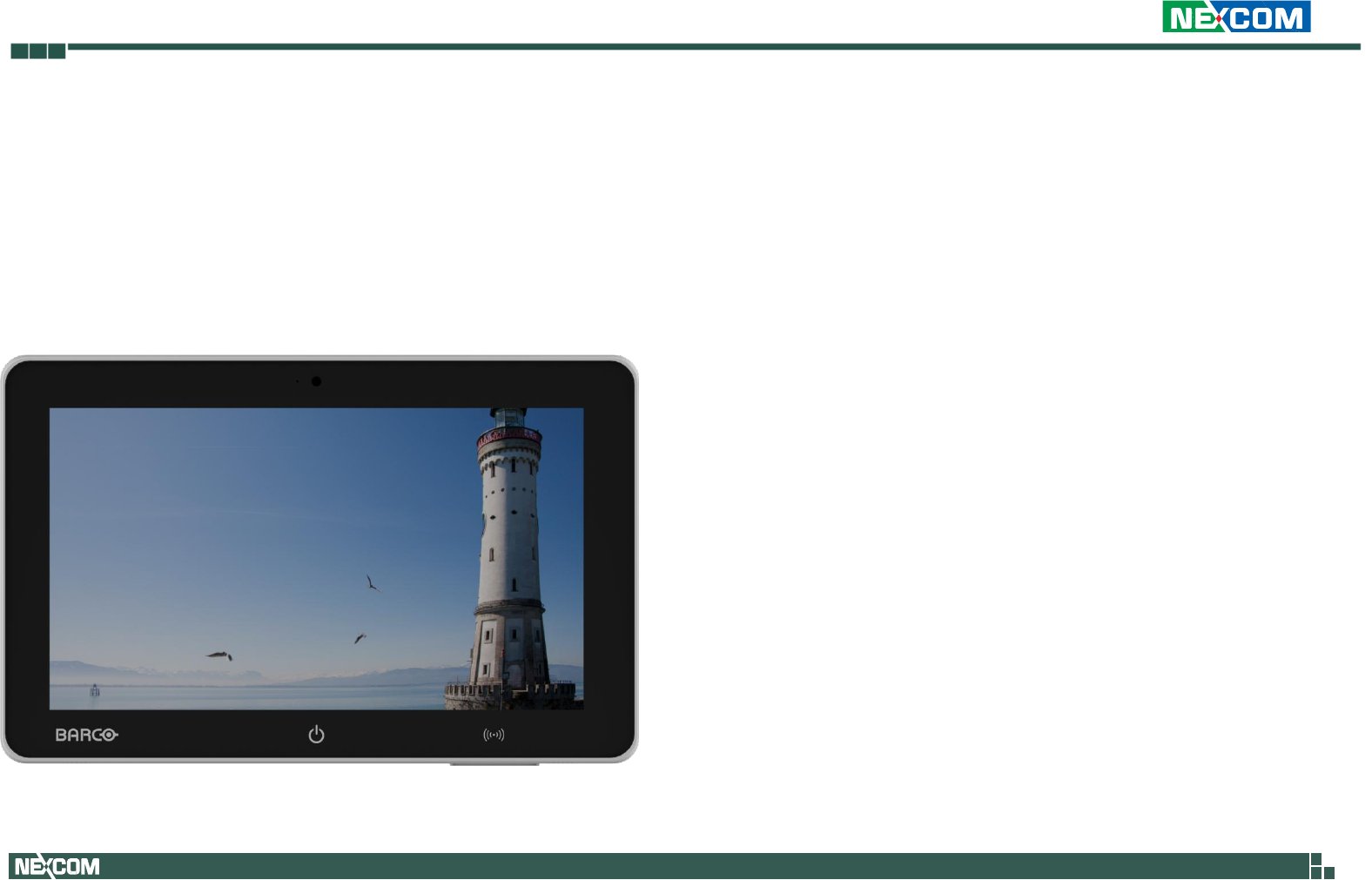
Chapter 1: Product Introduction
JAO15
Overview
Key Features
16:9 15.6” 1366x768 Fanless LED Panel Computer
Intel® Celeron® J1900, Quad Core, Low Consumption CPU
Flat Panel by Resistive Touch Screen
With 1x GbE/ HDMI input/ 5x USB ports
Built in speaker/ microphone/ 2x line out
13.56MHz RFID/ Smart card reader
DDR3L 2GB/ 2.5” 32GB SSD
Power Input 19V DC

Copyright 2013 NEXCOM International CO., Ltd. All Rights Reserved 9 VPPC 1632P/2132P User Manual
Specification
Panel
- LED size: 15.6”, 16:9
- Resolution: 1366x768
- Luminance: 300 cd/m2
- Contrast ratio: 500
- LED color: 16.7M
- Viewing Angle: 80(U) 80(D) 80(L) 80(R)
- Backlight: LED
Touch Screen
- 5 wire Resistive touch
- Light transmission: 78%
- Interface: USB
System
- CPU: On-board Intel® Celeron® J1900, 2.0GHz,2M L2 Cache
- BIOS: AMI BIOS
- IO chipset: ITE 8786
- System memory: 1x 204-pin DDR3L SO-DIMM socket, 2G
DDR3L (Default), support up to 8GB DDR3L-1333, Non-ECC
and un-buffered
- Storage Device: 1x 2.5” SATA HDD
- Watchdog timer: Watchdog timeout can be programmed by
software. from 1 second to 255 seconds and from 1 minute
to 255 minutes
(Tolerance 15% under room temperature 25°C)
- H/W status monitor: Monitoring system temperature, and
voltage
- Expansion: 1x mini-PCIe sockets
I/O
- Ethernet: 1x RJ45
- USB: 5 x USB 2.0
- Audio port: 2x Line out/built in speaker and microphone
- HDMI input connector
- Front touch icon
- 720p camera
Audio
- HDA codec: Realtek ALC886-GR
- Audio interface: Line out Audio Jack
Ethernet
- LAN chip: Intel® I210AT Gigabit LAN
- Ethernet interface: 10/100/1000 Based-Tx Ethernet
compatible

Copyright 2013 NEXCOM International CO., Ltd. All Rights Reserved 10 VPPC 1632P/2132P User Manual
Mechanical & Environment
- Color: white, pantone RAL9016
- IP protection: IP65 front
- Power input: 19V DC
- Power adapter: AC to DC power adaptor (+19V, 84W)
- Vibration:
IEC 68 2-64 (w/ HDD)
1Grms @ sine, 5~500Hz, 1hr/axis (HDD Operating)
- Shock:
IEC 68 2-27
HDD: 20G@panel mount, half sine, 11ms
- Operating temperature: 0°C to 40°C
- Storage temperature: -20°C to 60°C
- Operating humidity: 20%~80% relative humidity,
non-condensing
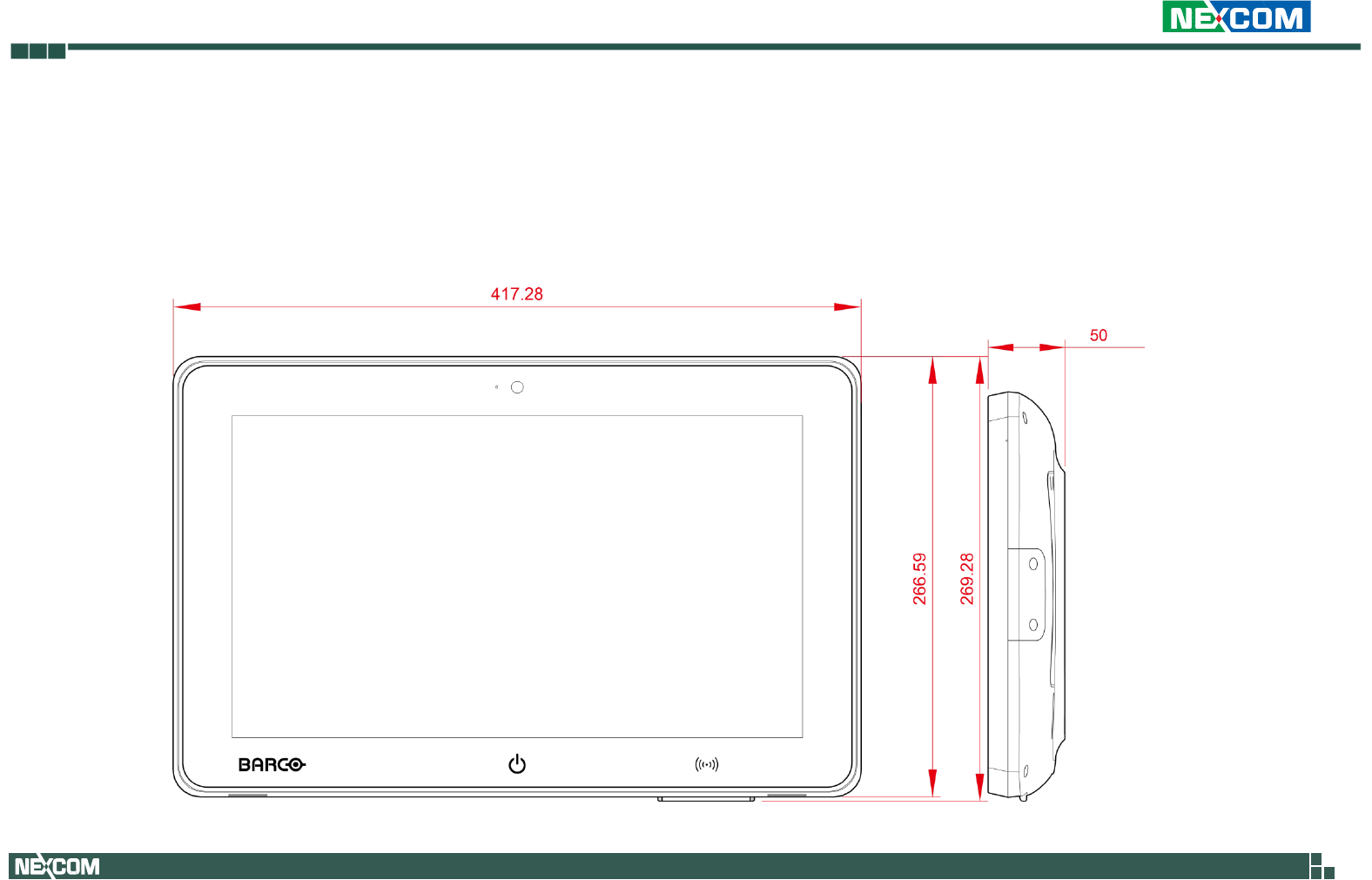
- Dimension: 417.2x 266.6x50 mm
- Weight: 4.5 Kg
Certifications
- CE
- FCC class B
- EN60601-1
- UL60601-1
- IEC 60950-1 CB
- ANSI/AAMI ES60601-1
- CAN/CSA-C22.2 No.60601-1
Copyright 2013 NEXCOM International CO., Ltd. All Rights Reserved 11 VPPC 1632P/2132P User Manual
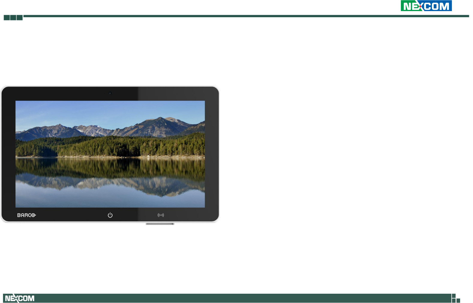
JAO18
Overview
Key Features
16:9 18.5” 1366x768 Fanless LED Panel Computer
Intel® Celeron® J1900, Quad Core, Low Consumption CPU
Flat Panel by PCAP Touch Screen
With 1x GbE/ HDMI input/ 5x USB ports
Built in speaker/ microphone/ 2x line out
13.56MHz and 125KHz dual RFID/ Smart card reader
DDR3L 2GB/ 2.5” 32GB SSD
Power Input 19V DC

Copyright 2013 NEXCOM International CO., Ltd. All Rights Reserved 12 VPPC 1632P/2132P User Manual
Specification
Panel
- LED size: 18.5”, 16:9
- Resolution: 1366X768
- Luminance: 300 cd/m2
- Contrast ratio: 1000
- LED color: 16.7M
- Viewing Angle: 80(U) 80(D) 85(L) 85(R)
- Backlight: LED
Touch Screen
- PCAP touch
- Light transmission: 87%
- Interface: USB
System
- CPU: On-board Intel® Celeron® J1900, 2.0GHz,2M L2 Cache
- BIOS: AMI BIOS
- IO chipset: ITE 8786
- System memory: 1x 204-pin DDR3L SO-DIMM socket, 2G
DDR3L (Default), support up to 8GB DDR3L-1333, Non-ECC
and un-buffered
- Storage Device: 1x 2.5” SATA HDD
- Watchdog timer: Watchdog timeout can be programmed by
software. from 1 second to 255 seconds and from 1 minute
to 255 minutes
(Tolerance 15% under room temperature 25°C)
- H/W status monitor: Monitoring system temperature, and
voltage
- Expansion: 1x mini-PCIe sockets
I/O
- Ethernet: 1x RJ45
- USB: 5 x USB 2.0
- Audio port: 2x Line out/built in speaker and microphone
- HDMI input connector
- Front touch icon
- 720p camera
Audio
- HDA codec: Realtek ALC886-GR
- Audio interface: Line out Audio Jack
Ethernet
- LAN chip: Intel® I210AT Gigabit LAN
- Ethernet interface: 10/100/1000 Based-Tx Ethernet
compatible

Copyright 2013 NEXCOM International CO., Ltd. All Rights Reserved 13 VPPC 1632P/2132P User Manual
Mechanical & Environment
- Color: white, pantone RAL9016
- IP protection: IP65 front
- Power input: 19V DC
- Power adapter: AC to DC power adaptor (+19V, 84W)
- Vibration:
IEC 68 2-64 (w/ HDD)
1Grms @ sine, 5~500Hz, 1hr/axis (HDD Operating)
- Shock:
IEC 68 2-27
HDD: 20G@panel mount, half sine, 11ms
- Operating temperature: 0°C to 40°C
- Storage temperature: -20°C to 60°C
- Operating humidity: 20%~80% relative humidity,
non-condensing
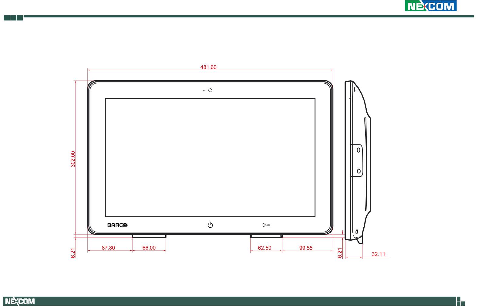
- Dimension: 481.6x308.2x50 mm
- Weight: 4.7 Kg
Certifications
- CE
- FCC class B
- EN60601-1
- UL60601-1
- IEC 60950-1 CB
- ANSI/AAMI ES60601-1
- CAN/CSA-C22.2 No.60601-1
Copyright 2013 NEXCOM International CO., Ltd. All Rights Reserved 14 VPPC 1632P/2132P User Manual
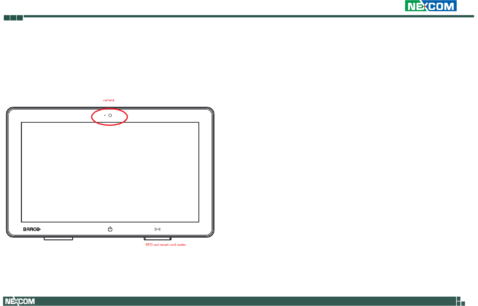
IO introduction
Front side
Camera
720p camera with white LED
RFID and smart card reader
13.56MHz and 125KHz dual RFID and smart card reader. RFID tag
also readable while parking in smart card reader slot
Power Key
Touch icon input. Long press 5 seconds to turn on panel
backlight; long press 10 seconds to reset or power off system.
Copyright 2013 NEXCOM International CO., Ltd. All Rights Reserved 15 VPPC 1632P/2132P User Manual
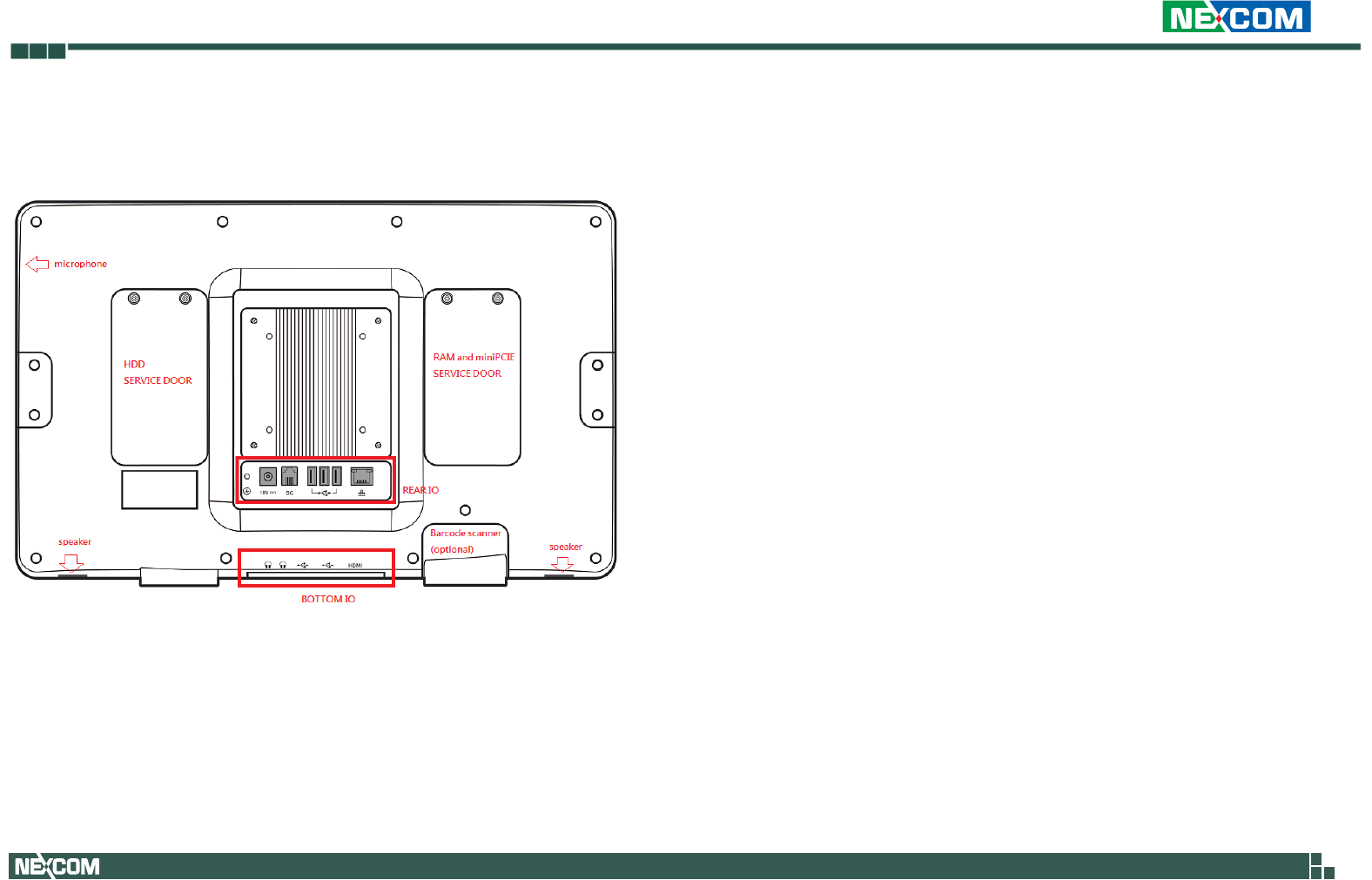
Back side
HDD service door
Lock with Torx screws, use for SSD replacement
RAM and miniPCIe service door
Lock with Torx screws, use for RAM replacement or install
extension module
Rear IO
19V DC input connect to PSU
Service call connect to nurse station with 4 wire signal pin
USB 3x USB 2.0 ports
LAN Gigabit Ethernet
Bottom IO
Line out 2x line out jack
USB 2x USB 2.0 ports with 1.5A V
HDMI use as HDMI input
Microphone
Built in digital microphone
Speaker
Built in stereo speaker
Copyright 2013 NEXCOM International CO., Ltd. All Rights Reserved 16 VPPC 1632P/2132P User Manual
Mechanical Dimensions
JAO15
Copyright 2013 NEXCOM International CO., Ltd. All Rights Reserved 17 VPPC 1632P/2132P User Manual
JAO18

Copyright 2013 NEXCOM International CO., Ltd. All Rights Reserved 18 VPPC 1632P/2132P User Manual
Chapter2: Jumpers and Connectors
This chapter describes how to set the jumpers and connectors on the
motherboard. Note that information in this chapter applies to VPPC1632P
and VPPC2132P.
Before you Begin
Ensure you have a stable, clean working environment. Dust and dirt can get
into components and cause a malfunction. Use containers to keep small
components separated.
Adequate lighting and proper tools can prevent you from accidentally
damaging the internal components. Most of the procedures that follow
require only a few simple tools, including the following:
- A Philips screwdriver
- A flat-tipped screwdriver
- A set of jewelers screwdrivers
- A grounding strap
- An anti-static pad
Using your fingers can disconnect most of the connections. It is
recommended that you do not use needle-nosed pliers to disconnect
connections as these can damage the soft metal or plastic parts of the
connectors.
Before working on internal components, make sure that the power is off.
Ground yourself before touching any internal components, by touching a
metal object. Static electricity can damage many of the electronic
components. Humid environments tend to have less static electricity than
dry environments. A grounding strap is warranted whenever danger of static
electricity exists.
Precautions
Computer components and electronic circuit boards can be damaged by
discharges of static electricity. Working on computers that are still
connected to a power supply can be extremely dangerous.
Follow the guidelines below to avoid damage to your computer or yourself:
Always disconnect the unit from the power outlet whenever you are
working inside the case.
If possible, wear a grounded wrist strap when you are working inside the
computer case. Alternatively, discharge any static electricity by touching the
bare metal chassis of the unit case, or the bare metal body of any other
grounded appliance
Hold electronic circuit boards by the edges only. Do not touch the
components on the board unless it is necessary to do so. Don’t flex or stress
the circuit board.
Copyright 2013 NEXCOM International CO., Ltd. All Rights Reserved 19 VPPC 1632P/2132P User Manual
Leave all components inside the static-proof packaging that they shipped
with until they are ready for installation. Use correct screws and do not over
tighten screws.
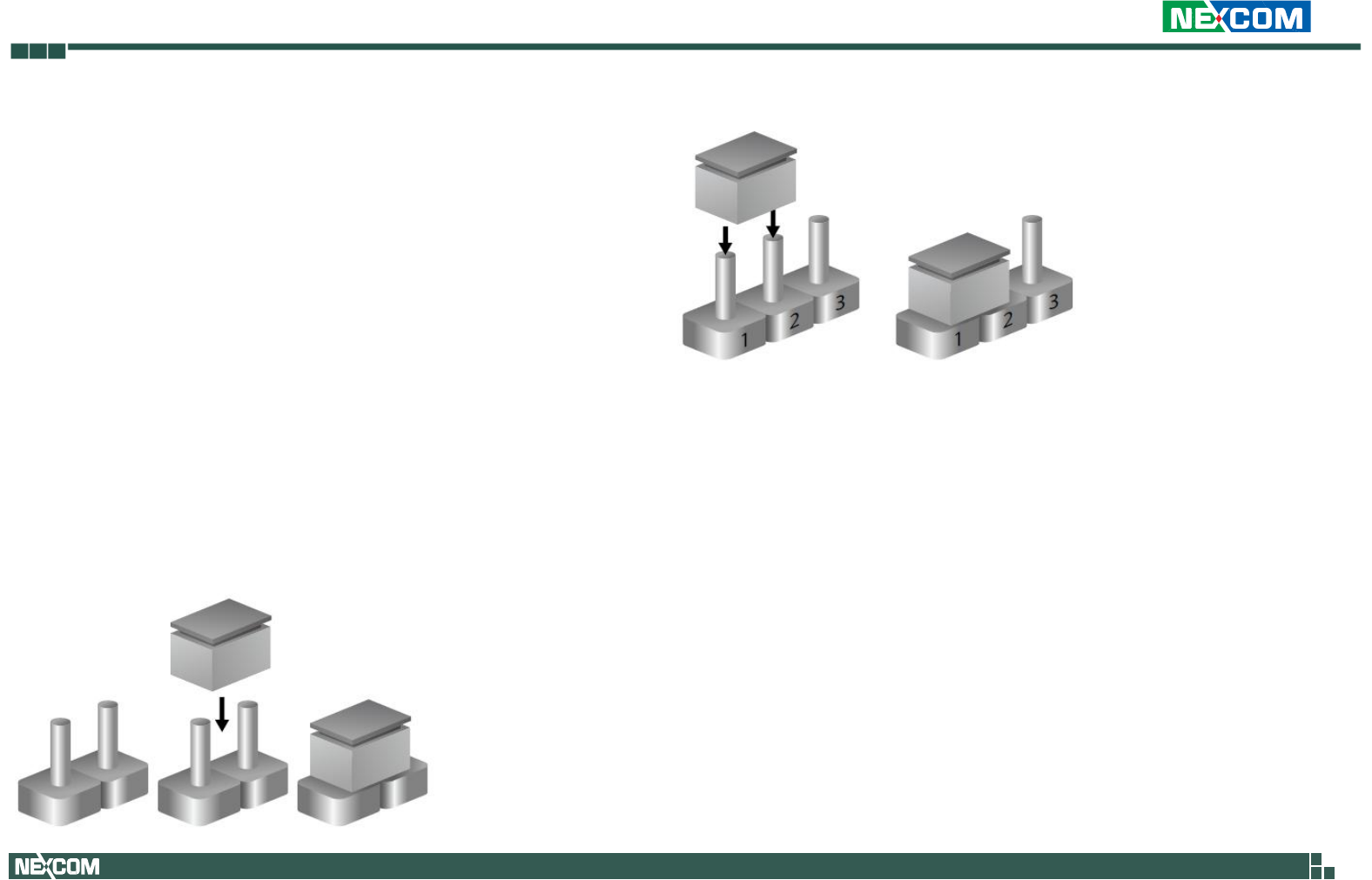
Jumper Setting
A jumper is the simplest kind of electric switch. It consists of two metal pins
and a cap. When setting the jumpers, ensure that the jumper caps are
placed on the correct pins. When the jumper cap is placed on both pins,
the jumper is short. If you remove the jumper cap, or place the jumper cap
on just one pin, the jumper is open.
Refer to the illustrations below for examples of what the 2-pin and 3-pin
jumpers look like when they are short (on) and open (off).
Two-Pin Jumpers: Open (Left) and Short (Right)
Three-Pin Jumpers: Pins 1 and 2 are Short
Copyright 2013 NEXCOM International CO., Ltd. All Rights Reserved 20 VPPC 1632P/2132P User Manual
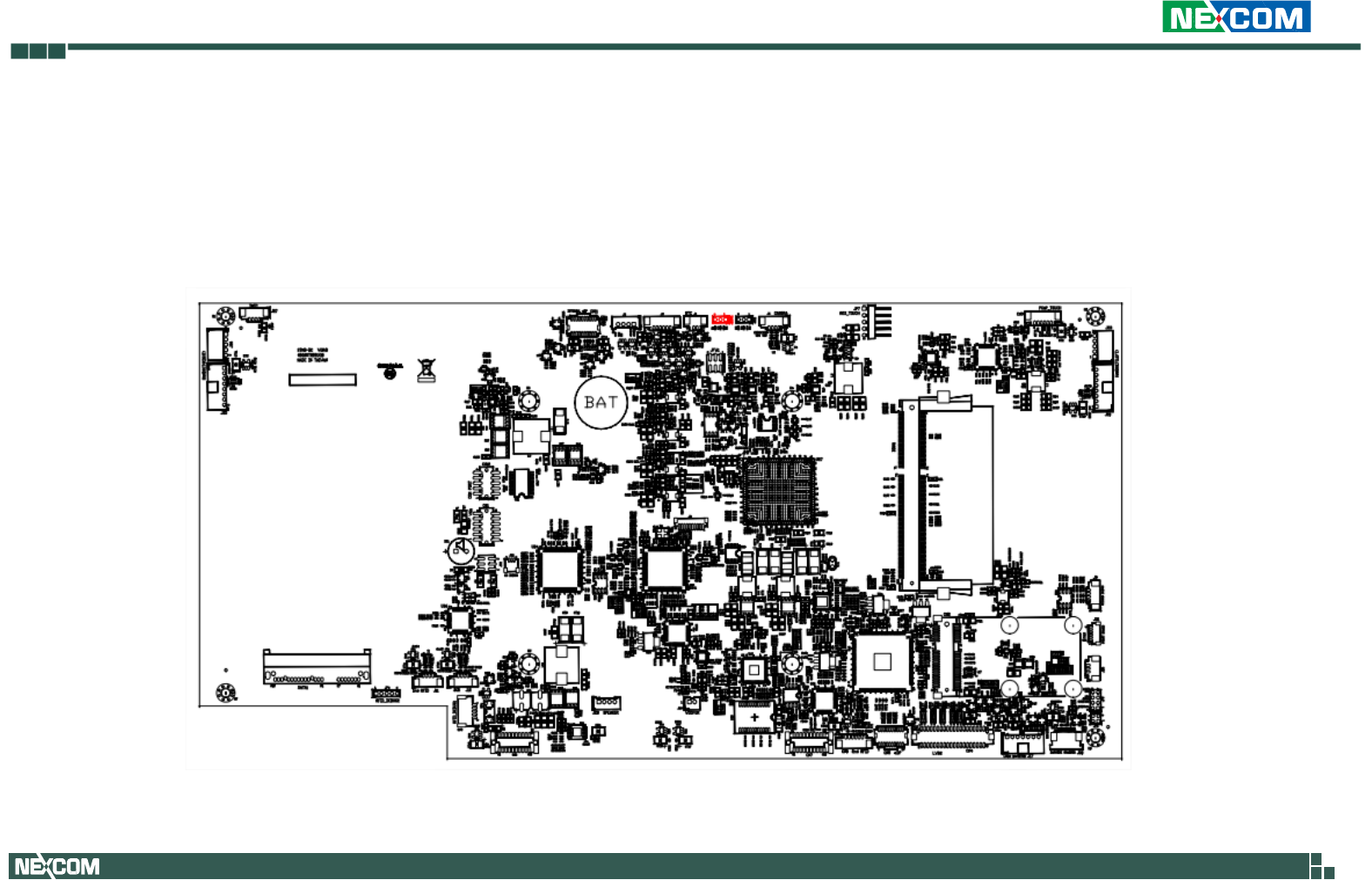
Locations of the Jumpers and Connectors
Top View
Copyright 2013 NEXCOM International CO., Ltd. All Rights Reserved 21 VPPC 1632P/2132P User Manual
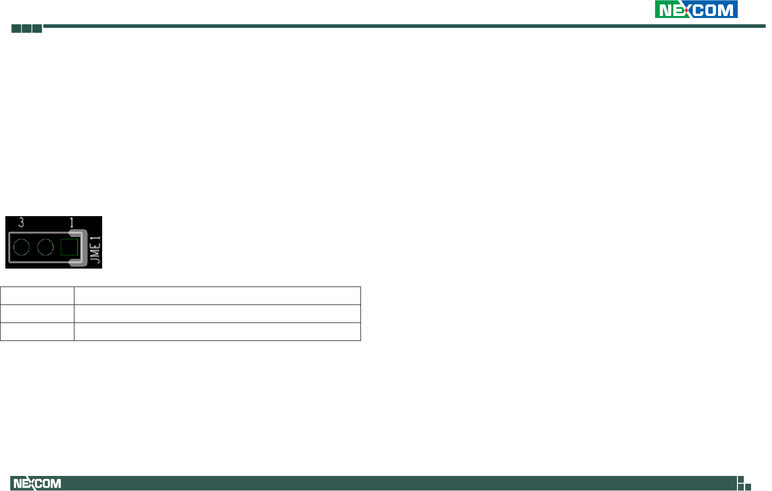
Jumpers and DIP Switch Setting
CMOS Clear Select
Connector type: 1x3 3-pin header, 2.54mm pitch
Connector location: JBIOS1
Pin
Settings
1-2 ON
Normal
2-3 ON
Clear BIOS
Copyright 2013 NEXCOM International CO., Ltd. All Rights Reserved 22 VPPC 1632P/2132P User Manual
Connector Pin Definition
External I/O Interface
19V DC Power Input
Connector type: 5.5mm DC jack
HDMI Input Port
Connector type: HDMI Female connector
Pin
Definition
Pin
Definition
1
TMDS Data2+
11
TMDS Clock Shield
2
TMDS Data2 Shield
12
TMDS Clock–
3
TMDS Data2–
13
CEC
4
TMDS Data1+
14
N.C
5
TMDS Data1 Shield
15
SCL
6
TMDS Data1–
16
SDA
7
TMDS Data0+
17
DDC/CEC Ground
8
TMDS Data0 Shield
18
+5 V Power
9
TMDS Data0–
19
Hot Plug Detect
10
TMDS Clock+
Copyright 2013 NEXCOM International CO., Ltd. All Rights Reserved 23 VPPC 1632P/2132P User Manual
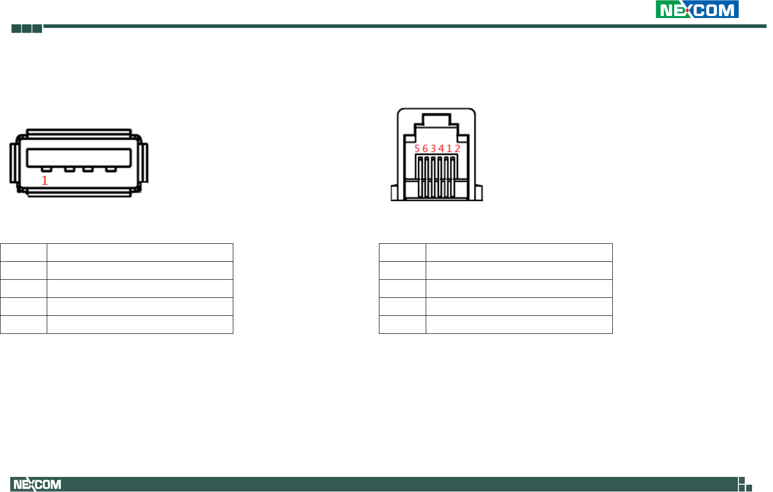
REAR IO USB PORT
Connector type: USB type A female
USB
Pin
Definition
1
VCC5
2
USB 0-
3
USB 0+
4
GND
Service Call connector
Connector type: 6 pin RJ 11 connector
Service call
Pin
Definition
2
Service call +
3
Service call -
4
Handset LED +
5
Handset LED -
Copyright 2013 NEXCOM International CO., Ltd. All Rights Reserved 24 VPPC 1632P/2132P User Manual
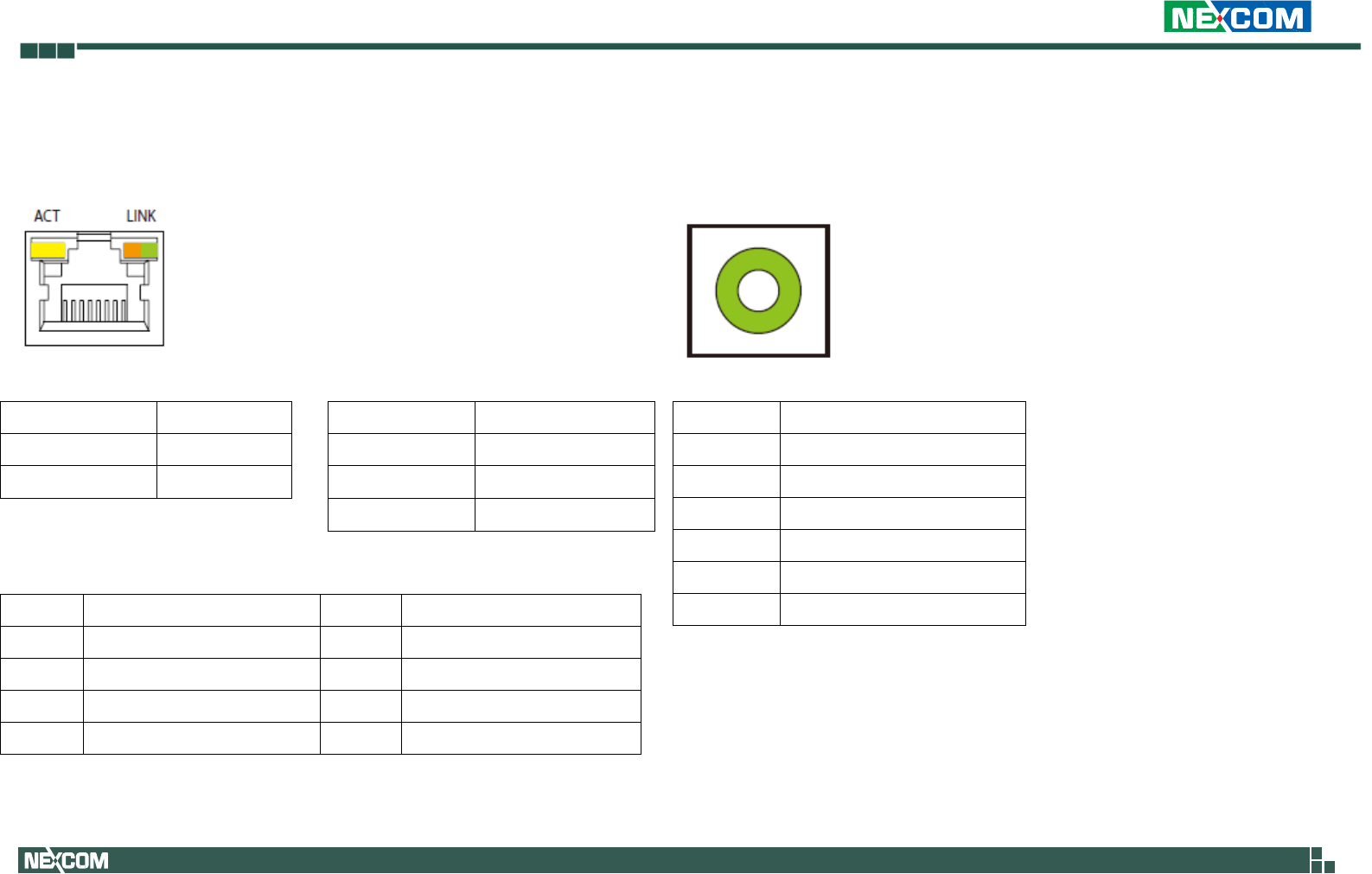
LAN Ports
Connector type: RJ45 port with LEDs
ACT
Status
LINK
Status
Yellow blinking
Data activity
Steady green
1000M link
Off
No activity
Steady orange
100M link
Off
10M or no link
Pin
Definition
Pin
Definition
1
LAN M0+
5
LAN M2-
2
LAN M0-
6
LAN M1-
3
LAN M1+
7
LAN M3+
4
LAN M2+
8
LAN M3-
Line-out Jack
Connector type: 3.5mm Earphone Jack
Pin
Definition
1
LOUT_R
2
JD
3
NC
4
LOUT_L
5
GND
6
GND
Copyright 2013 NEXCOM International CO., Ltd. All Rights Reserved 25 VPPC 1632P/2132P User Manual
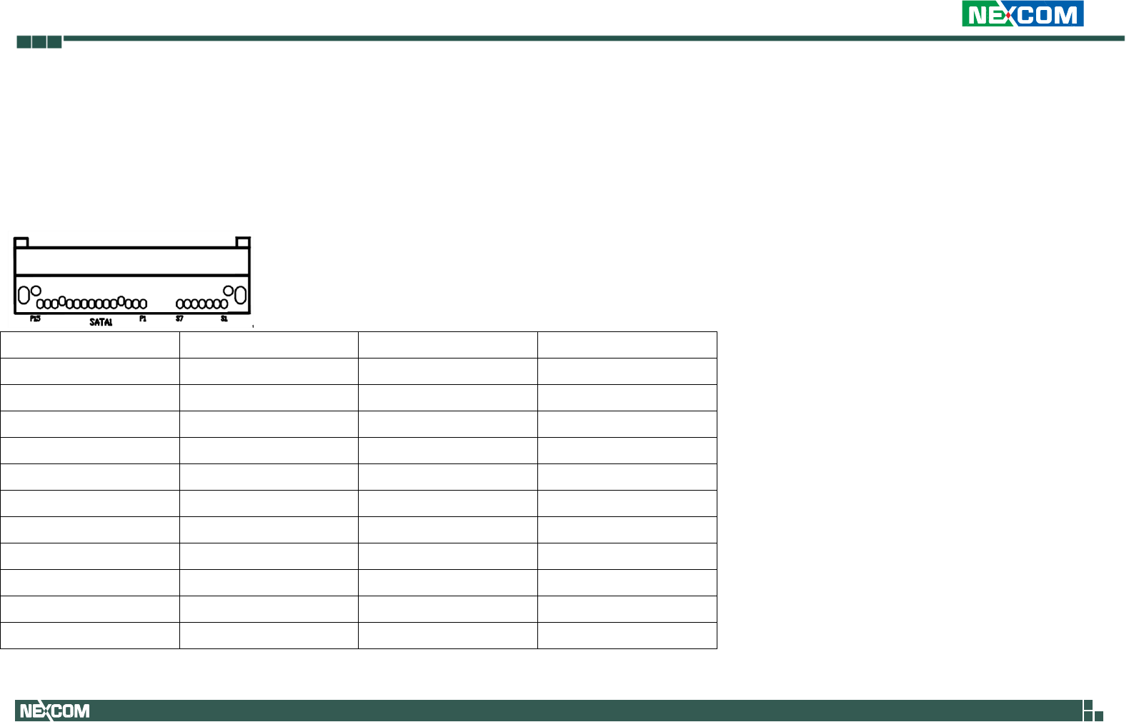
Internal Connectors
SATA
Connector location: SATA1
Pin
Signal
Pin
Signal
S1
GND
S2
SATA_TX0P
S3
SATA_TX0N
S4
GND
S5
SATA_RX0N
S6
SATA_RX0P
S7
GND
P1
VCC3
P2
VCC3
P3
VCC3
P4
GND
P5
GND
P6
GND
P7
VCC5
P8
VCC5
P9
VCC5
P10
GND
P11
NC
P12
GND
P13
VCC12
P14
VCC12
P15
VCC12
Copyright 2013 NEXCOM International CO., Ltd. All Rights Reserved 26 VPPC 1632P/2132P User Manual
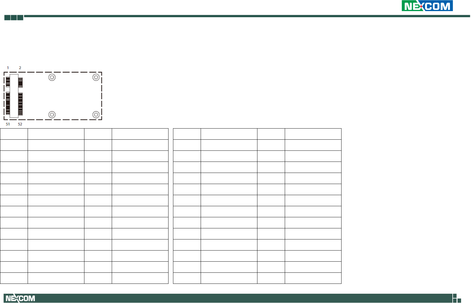
Mini-PCIe Slot
Connector location: CN2
Pin
Signal
Pin
Signal
Pin
Signal
Pin
Signal
1
WAKE0#
2
3.3V_MINI
27
GND
28
+1.5V_MINI
3
NC
4
GND
29
GND
30
SMB_CLK
5
NC
6
1.5V_MINI
31
PCIE_TX3-
32
SMB_DAT
7
PCIE_CLKREQ
8
NC
33
PCIE_TX3+
34
GND
9
GND
10
NC
35
GND
36
USB-
11
GPP_CLK1-
12
NC
37
GND
38
USB+
13
GPP_CLK1+
14
NC
39
+3.3V_MINI
40
GND
15
GND
16
NC
41
+3.3V_MINI
42
NC
17
NC
18
GND
43
GND
44
NC
19
NC
20
MINICARD1_DIS#
45
NC
46
NC
21
GND
22
PCIE_RST#
47
NC
48
+1.5V_MINI
23
PCIE_RX2-
24
3.3V_MINI
49
NC
50
GND
25
PCIE_RX2+
26
GND
51
NC
52
+3.3V_MINI
Copyright 2013 NEXCOM International CO., Ltd. All Rights Reserved 27 VPPC 1632P/2132P User Manual
Chapter 3: System Setup
Prior to removing the chassis cover, make sure the unit’s
power is off and disconnected from the power sources to
prevent electric shock or system damage.
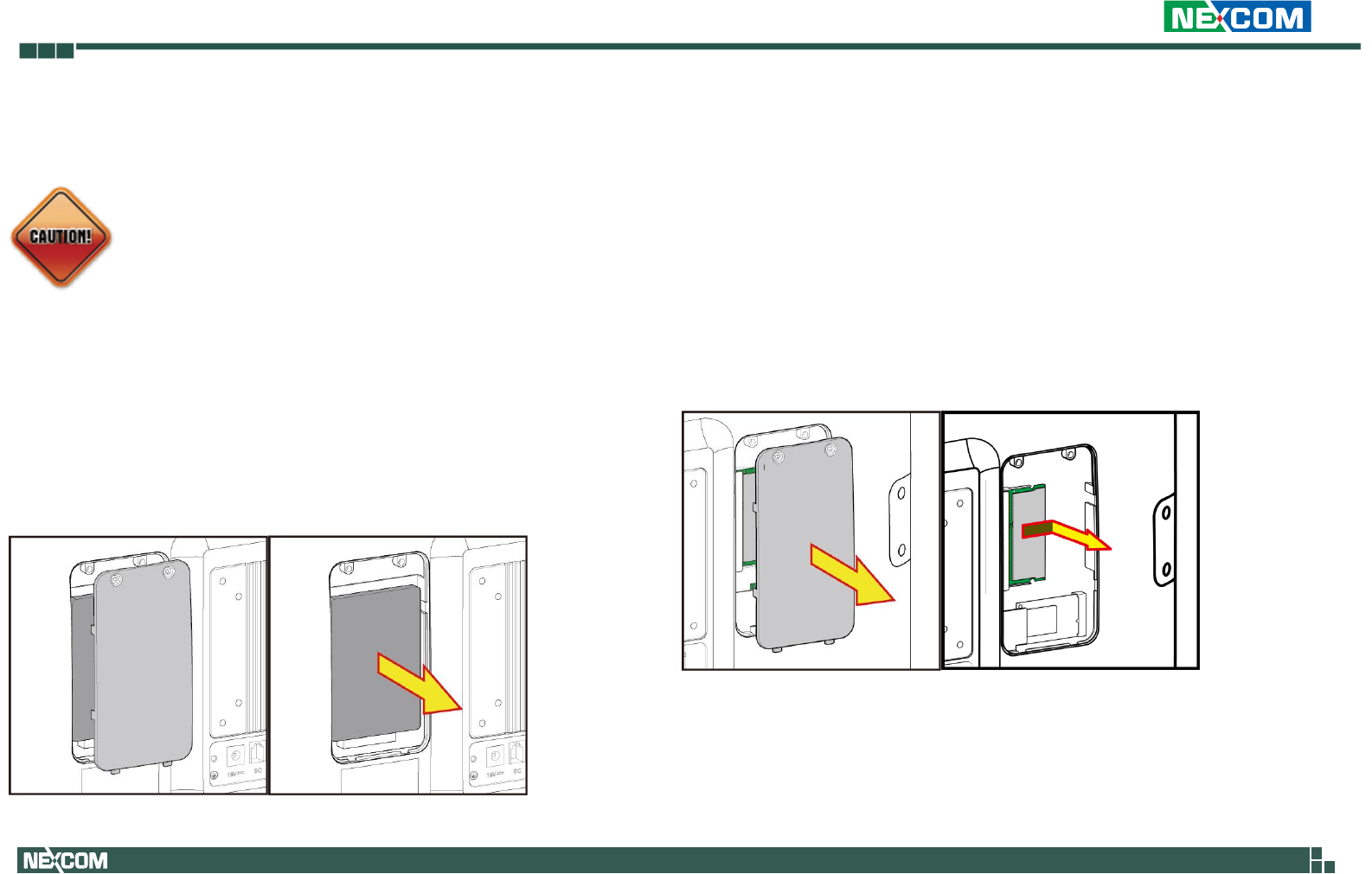
Replace SATA Disk
1. Loose the screw of HDD service door.
2. Remove current SATA and replace with new one.
Replace RAM
1. Loose the screw of RAM service door.
2. Remove DDR3L RAM module and replace with new one.
3.
Copyright 2013 NEXCOM International CO., Ltd. All Rights Reserved 28 VPPC 1632P/2132P User Manual
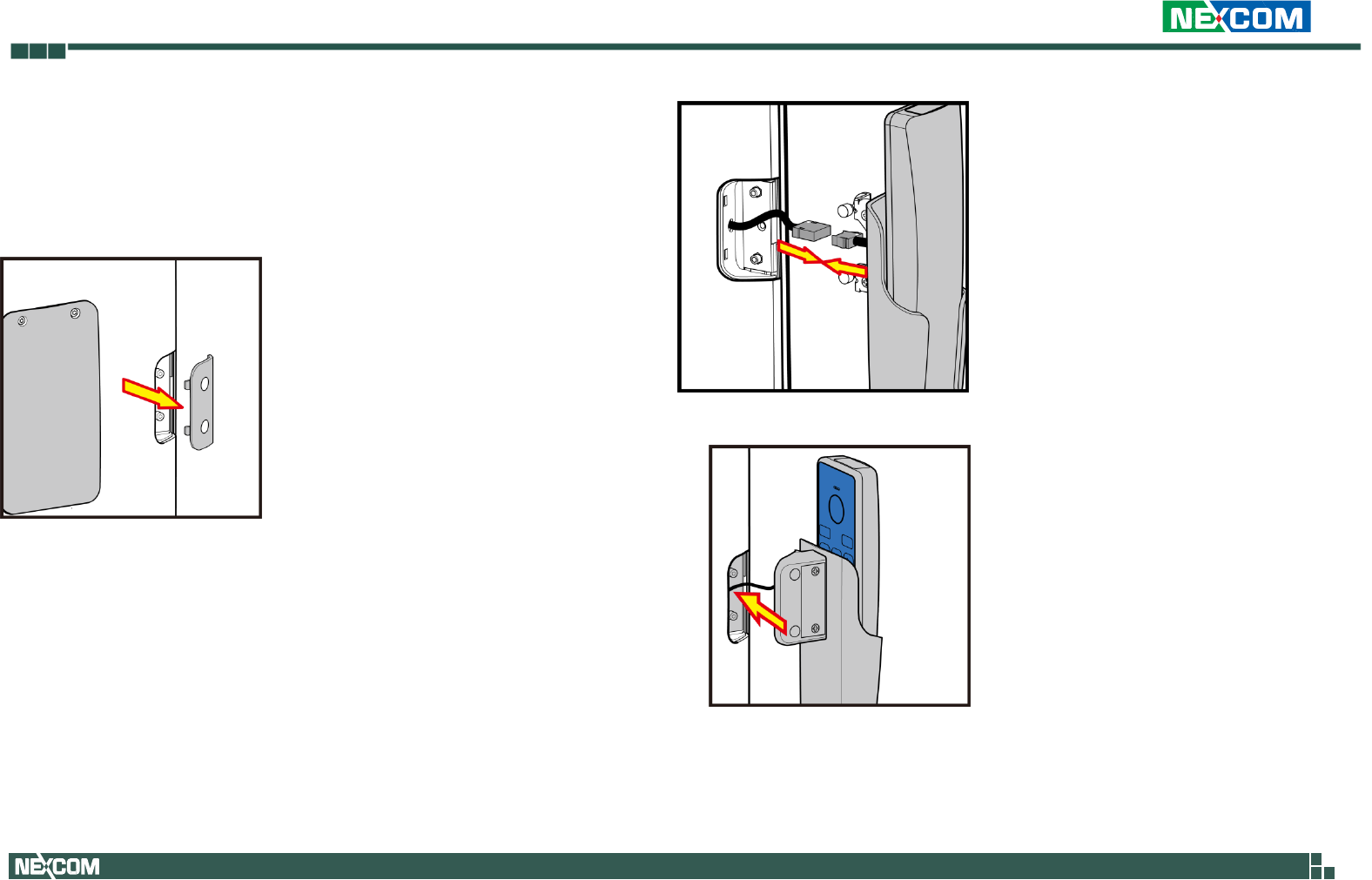
Install Handset
1. Remove handset side door.
2. Connects handset connector to cable behind the side door. Please connect
the white dot to white dot pin.
3. take screws in handset accessory and screw in the mounting

Copyright 2013 NEXCOM International CO., Ltd. All Rights Reserved 29 VPPC 1632P/2132P User Manual
Federal Communication Commission Interference Statement
This device complies with Part 15 of the FCC Rules. Operation is subject to the following two conditions: (1) This device may not cause harmful interference,
and (2) this device must accept any interference received, including interference that may cause undesired operation.
This equipment has been tested and found to comply with the limits for a Class B digital device, pursuant to Part 15 of the FCC Rules. These limits are
designed to provide reasonable protection against harmful interference in a residential installation. This equipment generates, uses and can radiate radio
frequency energy and, if not installed and used in accordance with the instructions, may cause harmful interference to radio communications. However,
there is no guarantee that interference will not occur in a particular installation. If this equipment does cause harmful interference to radio or television
reception, which can be determined by turning the equipment off and on, the user is encouraged to try to correct the interference by one of the following
measures:
Reorient or relocate the receiving antenna.
Increase the separation between the equipment and receiver.
Connect the equipment into an outlet on a circuit different from that
to which the receiver is connected.
Consult the dealer or an experienced radio/TV technician for help.
FCC Caution:
Any changes or modifications not expressly approved by the party responsible for compliance could void the user's authority to operate this
equipment.
This transmitter must not be co-located or operating in conjunction with any other antenna or transmitter.

Copyright 2013 NEXCOM International CO., Ltd. All Rights Reserved 30 VPPC 1632P/2132P User Manual
Radiation Exposure Statement:
This equipment complies with FCC radiation exposure limits set forth for an uncontrolled environment. This equipment should be installed and operated
with minimum distance 20cm between the radiator & your body.
Note: The country code selection is for non-US model only and is not available to all US model. Per FCC regulation, all WiFi product marketed in US must
fixed to US operation channels only.