Barco N V ST185C01 Panel PC User Manual
Barco N.V. Panel PC
User Manual
ST-185C
User Guide
K5903077/01
28/11/2013
Barco nv
President Kennedypark 35, 8500 Kortrijk, Belgium
Phone: +32 56.23.32.11
Fax: +32 56.26.22.62
Support: www.barco.com/esupport
Visit us at the web: www.barco.com
PrintedinBelgium

Table of contents
TABLE OF CONTENTS
1. Welcome! .......................................................................................... 3
1.1 About the product ............................................................................................. 3
1.2 What’s in the box.............................................................................................. 3
2. Parts, controls and connectors ............................................................... 5
2.1 System setup.................................................................................................. 5
3. System installation .............................................................................. 11
3.1 Mounting .......................................................................................................11
3.2 Installation of the ST-185C...................................................................................11
3.3 Installation of HDD, SSD (optional) .........................................................................12
3.4 Running the BIOS setup program...........................................................................12
3.5 Installing system software....................................................................................12
3.6 Installing the drivers ..........................................................................................13
4. System operation ................................................................................ 15
4.1 Frequently used functions....................................................................................15
5. Important information ........................................................................... 17
5.1 Safety information.............................................................................................17
5.2 Environmental information ...................................................................................19
5.3 Regulatory compliance information .........................................................................21
5.4 EMC notice ....................................................................................................22
5.5 Explanation of symbols.......................................................................................25
5.6 Legal disclaimer...............................................................................................27
5.7 Technical specifications ......................................................................................28
K5903077 ST-185C 28/11/2013 1

Table of contents
2K5903077 ST-185C 28/11/2013
1. Welcome!
1. WELCOME!
1.1 About the product
Smart Terminal
Thank you for choosing this Barco Smart Terminal: ST-185C.
The ST-185C is a multimedia Intel® Atom processor-based computer that is designed to serve as a Point
of Care (POC) and Point of Information terminal (POI) within healthcare applications. It is a PC based
system with 18.5" WXGA LED display, Gigabit Ethernet, multi-COM port and USB 2.0 interfaces and High
Definition Audio codec.
The ST-185C is as compact and user-friendly as a notebook computer. This simple, complete and highly
integrated multimedia system lets system integrators easily build the ST-185C into their applications.
The device is not intended to be used in patient monitoring, diagnosis, treatment, alle-
viation or prevention of diseases, injuries and handicaps.
CAUTION:Read all the important safety information before installing and operating your
ST-185C. Please refer to the dedicated chapter in this user guide.
1.2 What’s in the box
Overview
Your ST-185C comes with:
• PSU & Power cord — USA, European, UK types (where applicable)
• Handset & Coiled Cable (where applicable)
• Accessories for the ST-185C (where applicable)
Keep your original packaging. It is designed for this terminal and is the ideal protection during transport
and storage.
WARNING:To prevent electric shock, DO NOT remove covers. No user serviceable
parts inside, refer servicing to qualified personnel.
K5903077 ST-185C 28/11/2013 3

1. Welcome!
4K5903077 ST-185C 28/11/2013
2. Parts, controls and connectors
2. PARTS, CONTROLS AND
CONNECTORS
2.1 System setup
Become familiar
Before you set up the ST-185C, take a moment to become familiar with the locations and purposes of the
controls, drives, connections and ports, which are illustrated in the figures below.
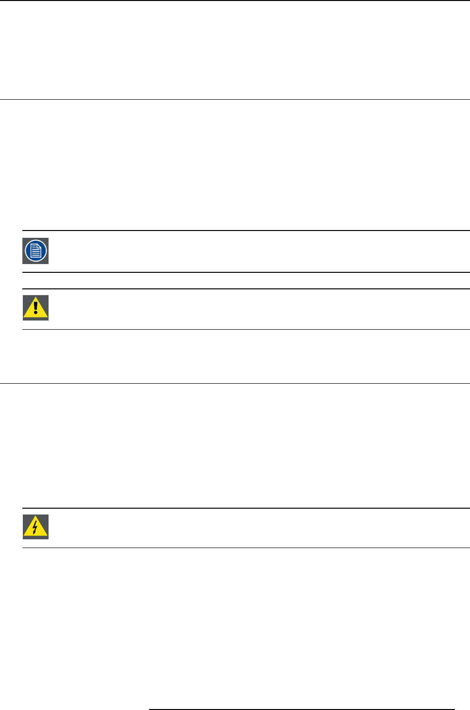
Front
When you place the ST-185C upright on the desktop, its front panel appears as shown in the figure below.
1
2
4
3
5
Image 2-1
Front view of the ST-185C
1Power button
2Membrane which contains functions Volume Up/Down, Backward/Forward, Stop, Play/Pause
and Channel Up/Down
3Handset (optional)
4Webcam
5External SCR (Smart Card Reader)
K5903077 ST-185C 28/11/2013 5
2. Parts, controls and connectors
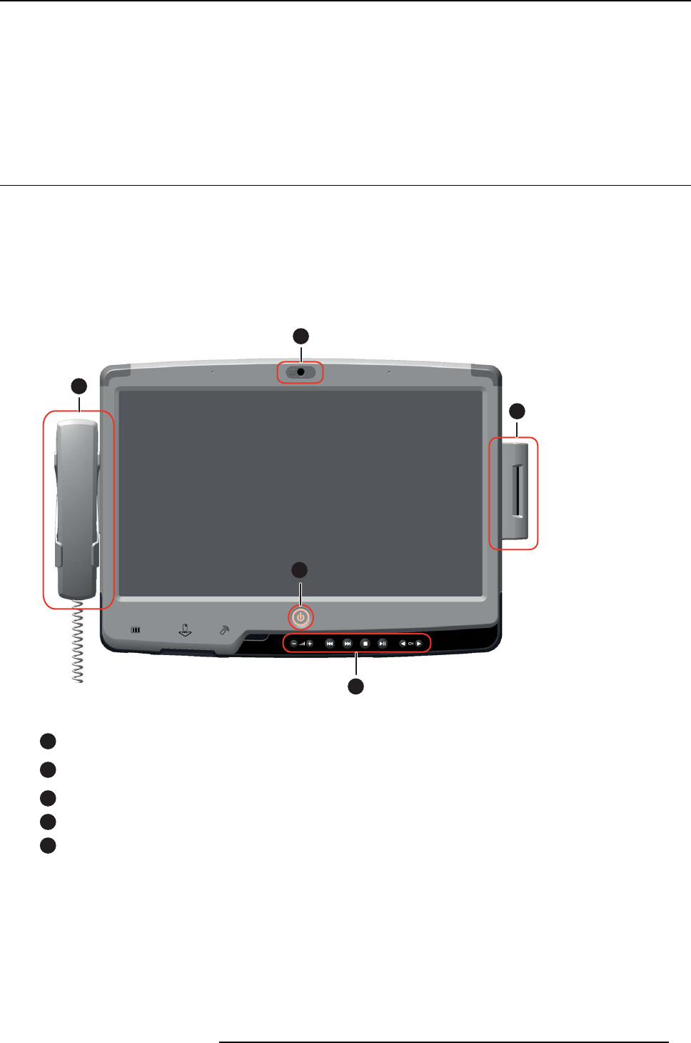
Left and Right
When you look at the left side of the ST-185C, you will see a handset, fitted to the left docking port. At
the right side of the terminal, you will see an external SCR (Smart Card Reader), fitted to the right docking
port.
Image 2-2
Left and Right side view of the ST-185C
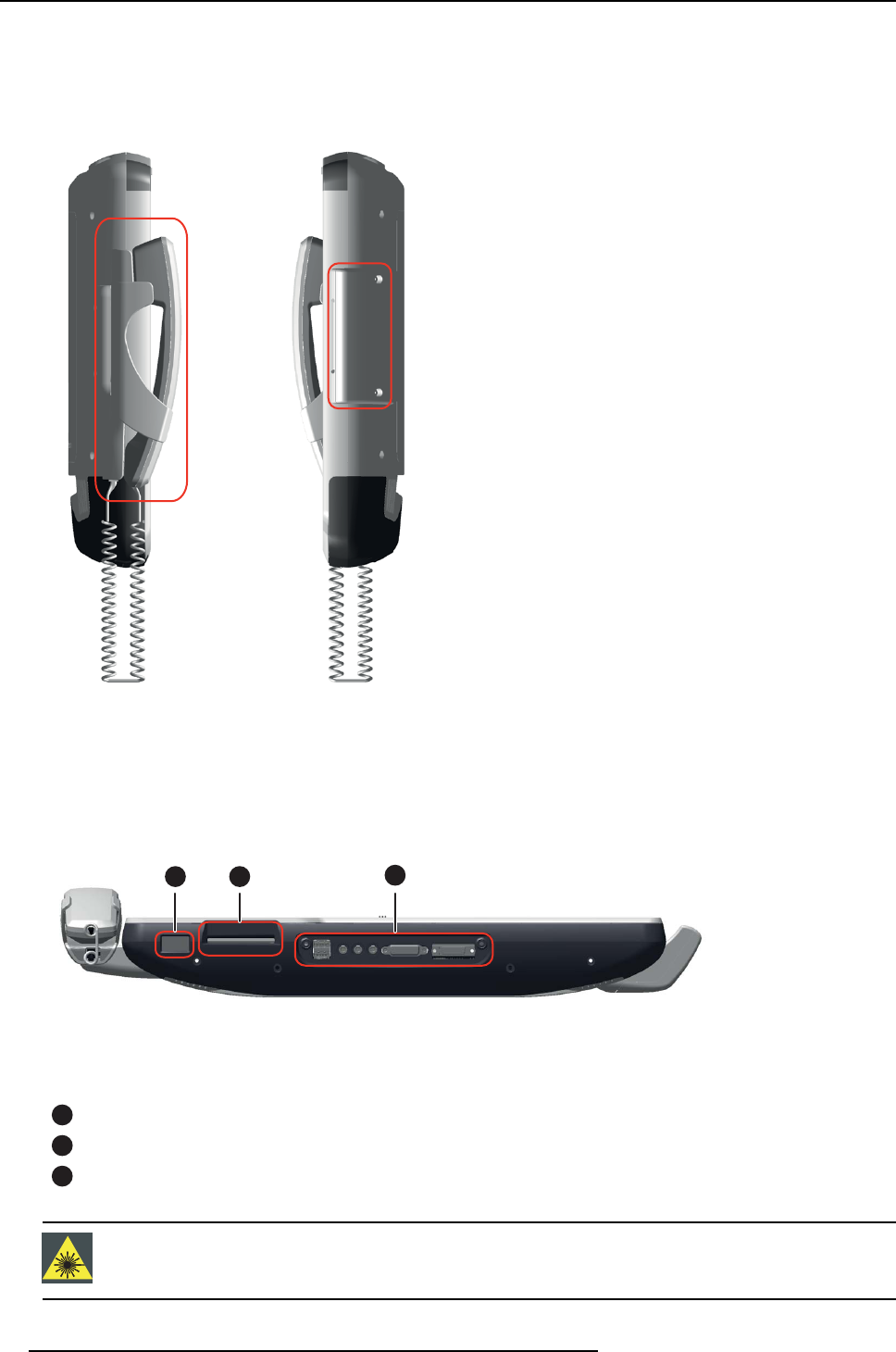
Bottom
On the bottom side of the ST-185C you will find the BarCode Scanner, a Smart Card Reader and an I/O
area, as shown in the figure below.
1 2 3
Image 2-3
Bottom view of the ST-185C
1BCS (BarCode Scanner)
2SCR (Smart Card Reader)
3I/O area bottom
WARNING:The BarCode Scanner exceeds Class 1 of the Accessible Emission Limit!
6K5903077 ST-185C 28/11/2013
2. Parts, controls and connectors
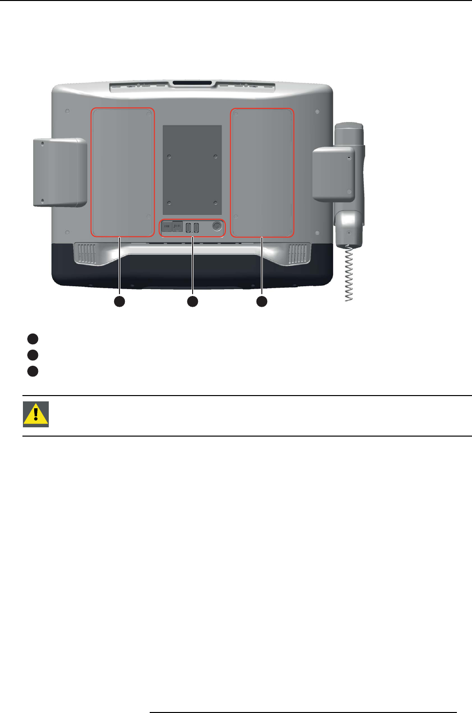
Rear
On the rear of the ST-185C you will find the two removable access doors located left and right of the
terminal. The right-hand cover provides access to the system DDR memory and a mini PCIe slot, and the
left-hand cover provides access to the HDD, as shown in the figure below.
21 3
Image 2-4
Rear view of the ST-185C
1Access door to HDD*
2I/O area rear
3Access door to System DDR memory and mini PCIe slot*
CAUTION:* The access doors may only be opened by qualified service personal, no
user serviceable parts inside.
K5903077 ST-185C 28/11/2013 7
2. Parts, controls and connectors
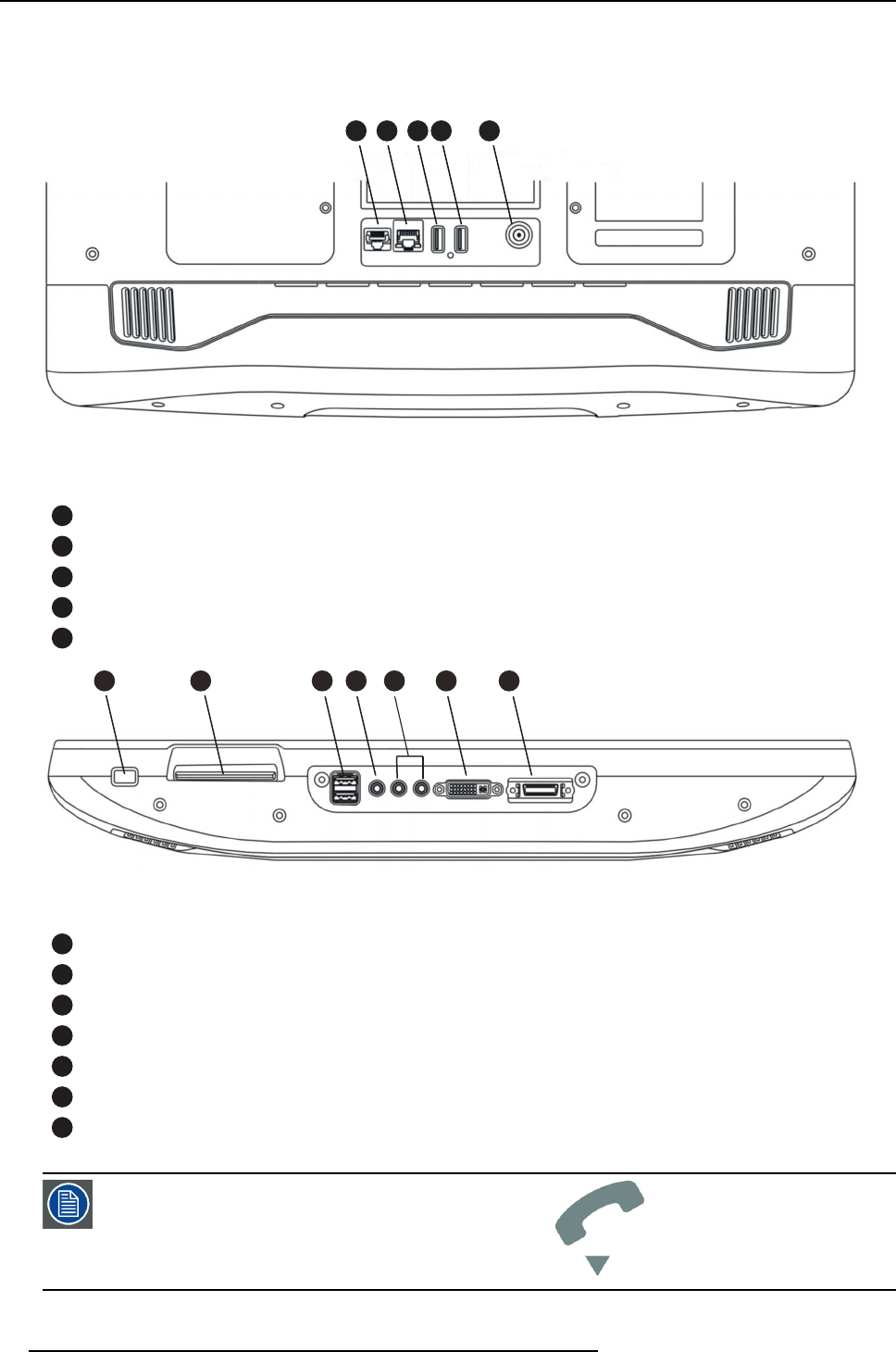
IO areas
There are two I/O areas in the ST-185C; one is at the rear and the other one is at the bottom. The figures
below indicate the various ports of these two areas.
1 2 3 4 5
Image 2-5
I/O ports at the rear of the ST-185C
18P8C handset connector +Fin Service Call Connector
2RJ 45 Shielded Gigabit Ethernet Connector
3USB Connector
4USB Connector
5Power Connector
1 2 3 4 5
6 7
Image 2-6
I/O ports at the bottom of the ST-185C
1USB Connector (2x)
2Microphone Jack
3Headset Jack (2x)
4DVI-I Connector
526-Way MDR Connector (for optional remote control or a Service Call device)
6BCS (BarCode Scanner) (optional)
7SCR (Smart Card Reader) (optional)
The RJ9 socket is for handset connection only.
8K5903077 ST-185C 28/11/2013
2. Parts, controls and connectors
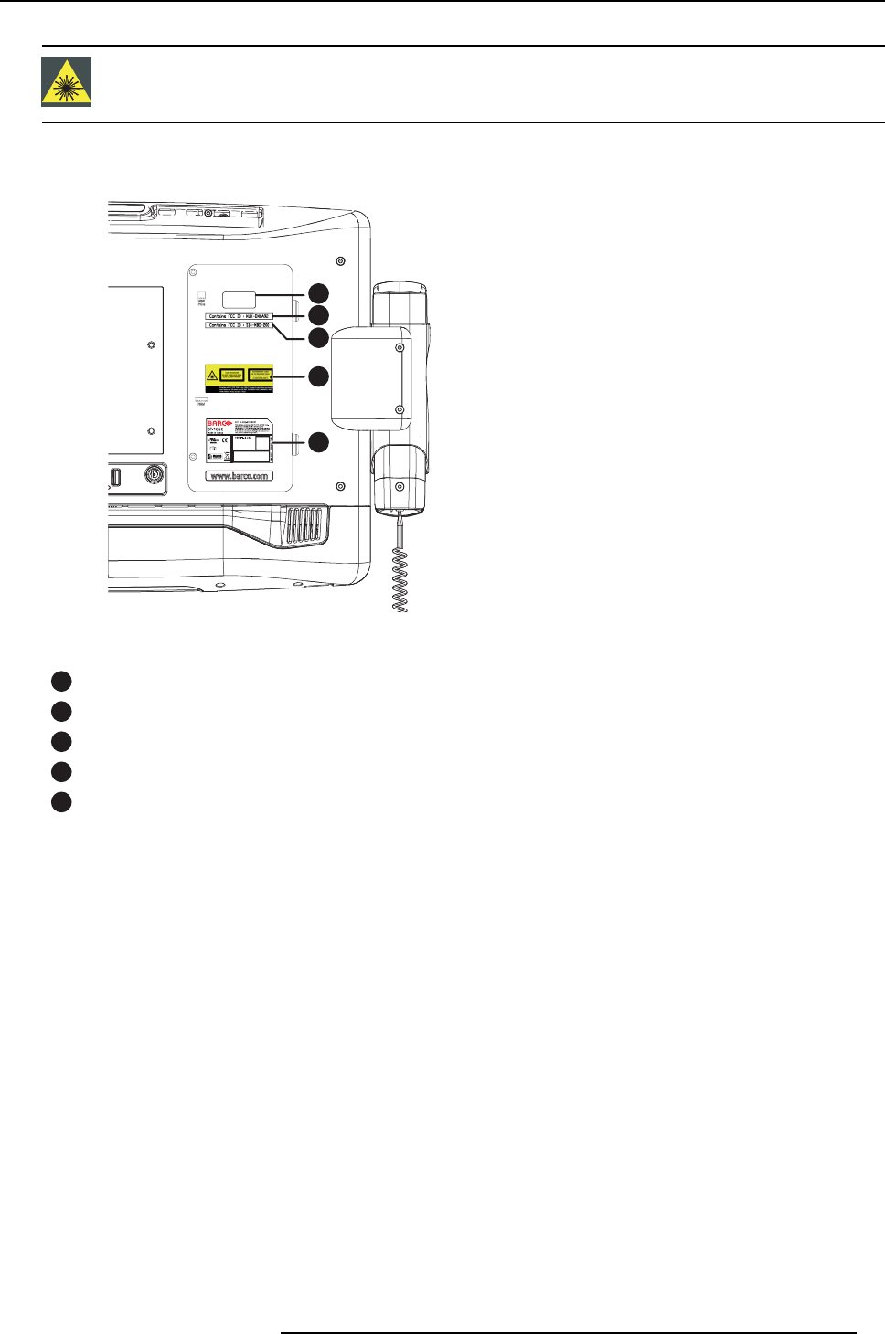
WARNING:The BarCode Scanner exceeds Class 1 of the Accessible Emission Limit!
Label location
2
1
3
4
5
Image 2-7
Label location
1Intel® label
2FCC label WiFi module
3FCC label Bluetooth
4BCS laser radiation warning label
5Rating label
K5903077 ST-185C 28/11/2013 9

2. Parts, controls and connectors
10 K5903077 ST-185C 28/11/2013
3. System installation
3. SYSTEM INSTALLATION
3.1 Mounting
Fixing the terminal to a mounting solution
The terminal is foreseen from a mounting anchor that can be used for different mounting solutions (arms,
desk stands, ...).
To install the terminal, please follow the detailed mounting instructions in the user guide, which is delivered
with the mounting solution you have chosen for your terminal.
3.2 Installation of the ST-185C
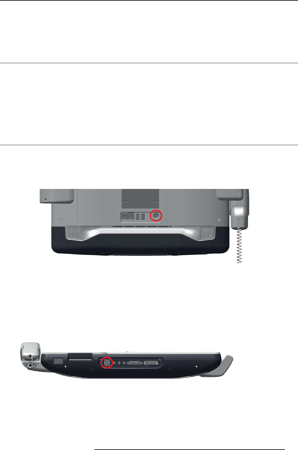
Connecting the power cable
Always handle the power cable by holding the plug end only. Follow these steps:
1. Connect the male end of the power supply DIN cable to the DC inlet of the ST-185C, see figure below
and connector 3 in the image 2-5.
Image 3-1
Connecting the power cable
2. Connect the male plug of the power supply to an electrical outlet.
Connecting USB keyboard and mouse
1. Connect the keyboard and mouse to the USB ports located on the bottom cover of the ST-185C, see
figure below and connector 1 in image 2-6.
Image 3-2
Connecting the keyboard and mouse
Switching on the power
1. Switch on the ST-185C via the power switch on the front cover (See figure below).
K5903077 ST-185C 28/11/2013 11
3. System installation
Image 3-3
Switching on the power
3.3 Installation of HDD, SSD (optional)
CAUTION:The installation of the optional HDD and/or SSD drive should be carried out
by a professional technician. Only UL-certified hard disks may be installed!
Please contact a service technician or your reseller if you need this service.
3.4 Running the BIOS setup program
BIOS setup
Your ST-185C is likely to have been properly set up and configured by your dealer prior to delivery. If
you still find it necessary to use the BIOS (Basic Input-Output System) setup program to change system
configuration information please contact Barco for support.
The settings you specify with the setup program are recorded in a special area of memory called CMOS
RAM. This memory is backed up by a battery so that it will not be erased when you turn off or reset
the system. Whenever you turn on the power, the system reads the settings stored in CMOS RAM and
compares them to the equipment check conducted during the power on self-test (POST). If an error occurs,
an error message will be displayed on screen, and you will be prompted to run the setup program.
3.5 Installing system software
Setup and installation instructions
Recent releases of operating systems from major vendors include setup programs which load automati-
cally and guide you through hard disk preparation and operating system installation. The guidelines below
will help you determine the steps necessary to install your operating system on the ST-185C. If required,
insert your operating system’s installation or setup disc into a portable optical drive and plug into one of
the ST-185C USB ports.
Some distributors and system integrators may have already pre-installed system soft-
ware prior to shipment of your ST-185C.
If you are presented with a setup/installation screen then carefully follow the instructions. The setup pro-
gram will guide you through preparation of your hard drive, and installation of the operating system.
12 K5903077 ST-185C 28/11/2013

3. System installation
3.6 Installing the drivers
Drivers
After installing the system software, you will be able to install the necessary drivers. All the ST-185C
drivers and updates can be obtained from Barco.
The drivers and utilities used for the ST-185C are subject to change without notice. If
in doubt, check with your local Barco office or contact our application engineers for the
latest information regarding drivers and utilities.
K5903077 ST-185C 28/11/2013 13

3. System installation
14 K5903077 ST-185C 28/11/2013
4. System operation
4. SYSTEM OPERATION
4.1 Frequently used functions
Using the BarCode Reader (BCR)
The integrated BCS can be used to scan barcodes (e.g. found on patient identification bracelets, or on
medication bottles) next to the patients bedside. This to ensure better quality of care with lower probability
of error.
1. Present the barcode to be scanned under the aperture at the bottom of the terminal clearly marked with
the BCS symbol, and the barcode will be scanned (See figure below).
Image 4-1
Using the BarCode Scanner (BCS)
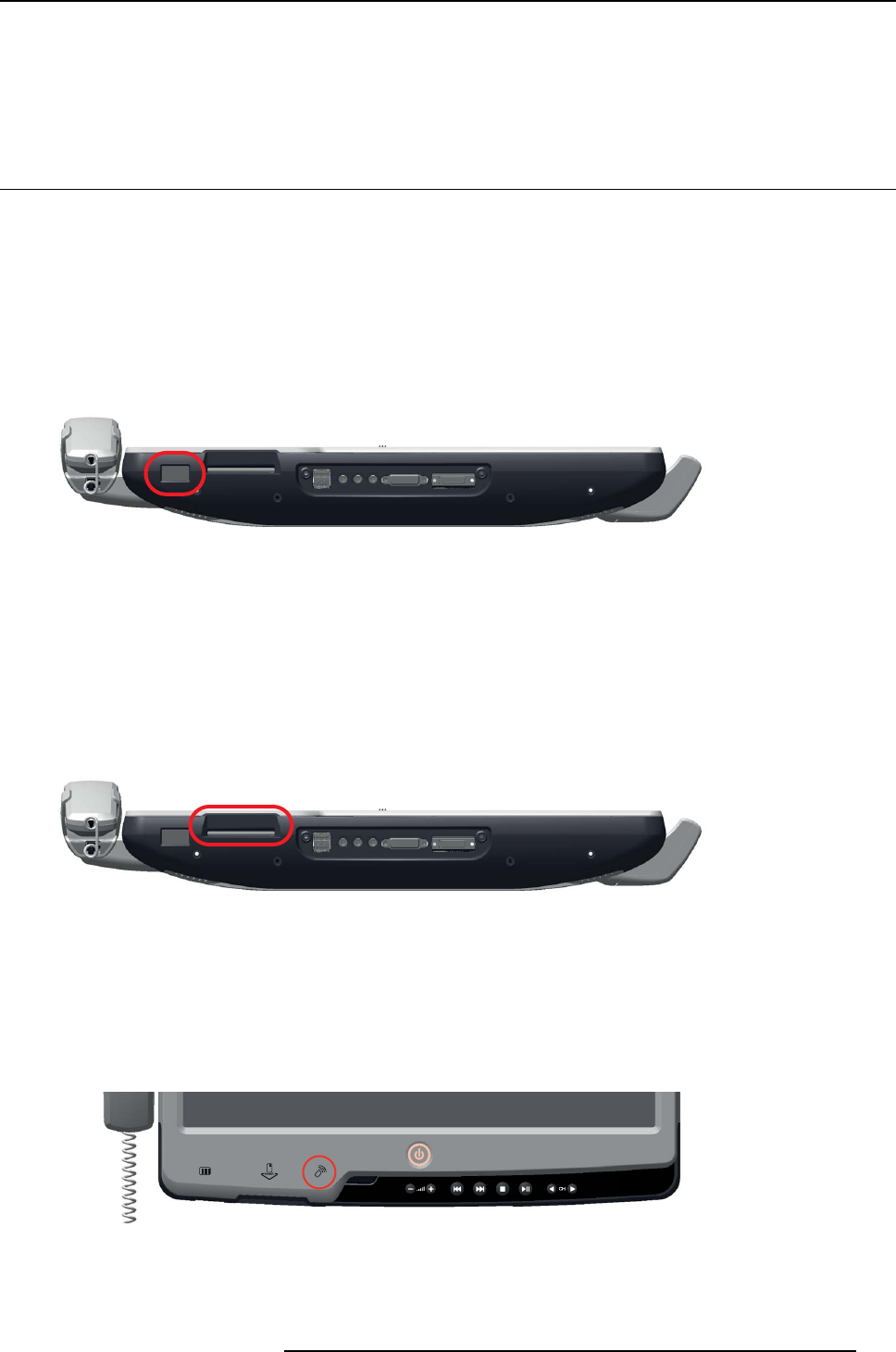
Using the Smart Card Reader (SCR)
1. Insert the card firmly into the allocated slot with the chip facing towards the front of the terminal. (See
figure below). The Smart Card will be recognized by the terminal.
Image 4-2
Using the Smart Card Reader (SCR)
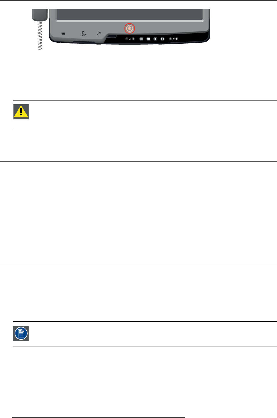
Using the RFID Reader
1. Present the card to the reader by tapping and holding it briefly onto the clearly reader-marked area until
the card is read.
Image 4-3
Using the RFID reader
K5903077 ST-185C 28/11/2013 15
4. System operation
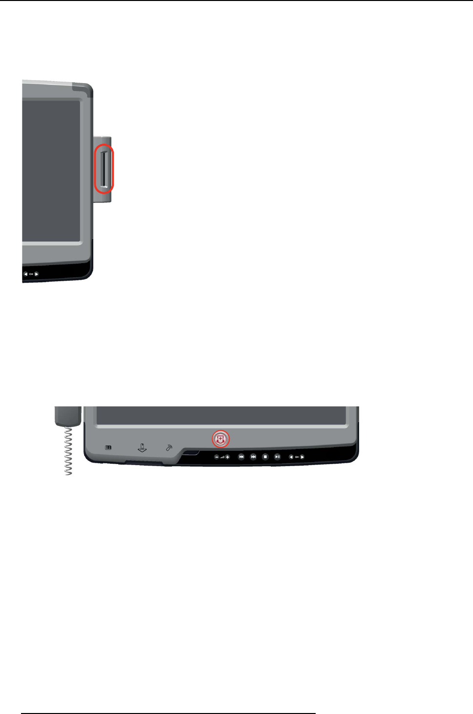
Using the external SCR (Smart Card Reader)
1. Insert the card firmly into the allocated slot with the chip facing towards the side of the terminal. (See
figure below). The Smart Card will be recognized by the terminal.
Image 4-4
Using the external SCR (Smart Card Reader)
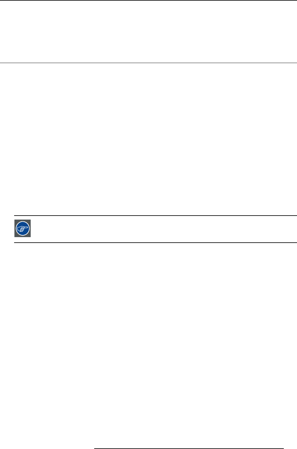
Using Service call
The service call button (optional button on the front of the terminal, replacing the power button) can be
used in case there is need to call a nurse for some service, independent of a medical need.
1. Push the Service Call button to start a service call to a nurse (See figure below).
2. The nurse will need to press the button again to deactivate the call.
Image 4-5
Using Service call
16 K5903077 ST-185C 28/11/2013
5. Important information
5. IMPORTANT INFORMATION
5.1 Safety information
General recommendations
Read the safety and operating instructions before operating the device.
Retain safety and operating instructions for future reference.
Adhere to all warnings on the device and in the operating instructions manual.
Follow all instructions for operation and use.
Electrical Shock or Fire Hazard
To prevent electric shock or fire hazard, do not remove cover.
No serviceable parts inside. Refer servicing to qualified personnel.
Do not expose this apparatus to rain or moisture.
Safety instructions
• The equipment must be powered using the delivered medical approved DC power supply only.
• The medical approved DC power supply must be powered by the AC mains voltage (protective earth
terminal).
To avoid the risk of electric shock, this equipment must only be connected to a supply
mains with protective earth.
• Make sure the voltage of the power source is correct before connecting the equipment to the power
outlet.
• Position the power cord so that it is not a hazard. Do not place anything over the power cord.
• If the equipment is out of use for an extended period, make sure to disconnect it from the power source
to avoid damage in the event of a power surge.
• Earth the ST-185C by connecting the protective earth pin to a grounded outlet by means of the sup-
plied wire.
• If one of the following situations arises, ensure you get the equipment checked by service personnel:
a) The power cord or plug is damaged.
b) The equipment has been exposed to moisture.
c) The equipment is not functioning properly, or you cannot get it to work according to the user manual.
d) The equipment has been dropped and damaged.
e) The equipment has obvious signs of breakage.
• To disconnect the device: Remove the rear power supply power connection.
• If your computer is losing time or the BIOS configuration resets to default settings, the battery most
likely has no power.
• Do not replace the battery yourself. Please contact a qualified technician or your supplier of the
ST-185C. The ST-185C is provided with a battery-powered real-time clock circuit. There is a danger
of leakage or explosion if the battery is incorrectly replaced. Replace only with same or equivalent
type recommended by the manufacturer. Discard used batteries according to the manufacturer’s in-
structions.
K5903077 ST-185C 28/11/2013 17

5. Important information
•Warning: if the equipment is not used for a long time, please make sure that the battery is removed
from the equipment.
• Place the terminal on a stable surface that can support the weight of at least 4 terminals or hang from
a reliable structure during installation. Dropping the equipment is likely to cause serious injury to a
child or adult, and serious damage to the equipment.
• Improper installation of VESA mounting can result in serious personal injury! Use a VESA mounting
solution that can support a weight of at least 10kg. VESA mount installation should be carried out by a
professional technician. Please contact the service technician or your reseller if you need this service.
• Keep this equipment away from excessive humidity.
• Do not pour any liquid into the vents on the terminal. This may cause fire or electrical shock.
• The vents on the enclosure are for air convection and protect the equipment from overheating. Do not
cover the vents.
When installing the terminal in a cupboard or another closed location, heed the necessary space be-
tween the set and the sides of the cupboard.
• Do not leave this equipment in an uncontrolled environment where the storage temperature is below
-20 °C or above 60°C. This may damage the equipment.
• Equipment not suitable for use in the presence of a flammable anesthetic mixture with air or with
oxygen or nitrous oxide.
• For more information about recycling of this product, please contact your local city office, your munic-
ipal waste disposal service or the shop where you purchased the product.
• This equipment is not intended to be used in life support systems, operating rooms or for diagnostic
purposes.
• External connections to model ST-185C (I/O, LAN, etc) shall be in compliance with the requirements
for medical electrical systems as stated in chapter 16 of the standard for medical electrical equipment
IEC 60601-1: 2005.
• Accessory equipment connected to the analog and digital interfaces must be in compliance with the
respective nationally harmonized IEC standards (i.e. IEC 60601 for data processing equipment). If in
doubt, consult the technical services department or your local representative.
Type of protection (electrical):
Display with external power supply: Class I equipment.
Degree of safety (flammable anesthetic mixture):
Equipment not suitable for use in the presence of a flammable anesthetic mixture with air or with oxygen
or nitrous oxide.
Non-patient care equipment
• Equipment primarily for use in a health care facility that is intended for use where contact with a patient
is unlikely (no applied part).
• The equipment may not be used with life support equipment.
• The user is not supposed to touch SIP/SOPs and the patient at the same time.
Power connection – Equipment with external 19 VDC power supply
• Power requirements: The equipment must be powered using the delivered medical approved 19 VDC
() power supply.
• The medical approved DC ( ) power supply must be powered by the AC mains voltage.
• The power supply is specified as a part of the ME equipment or combination is specified as a ME
system.
• To avoid the risk of electric shock, this equipment must only be connected to a supply mains with
protective earth.
• The equipment should be installed near an easily accessible outlet.
• The equipment is intended for continuous operation.
18 K5903077 ST-185C 28/11/2013
5. Important information
Transient over-voltage
If the device is not used for a long time, disconnect it from the AC inlet to avoid damage by transient
over-voltage.
To fully disengage the power to the device, please disconnect the power cord from the AC inlet.
Power cords:
• Utilize a UL-listed detachable power cord, 3-wire, type SJ or equivalent, 18 AWG min., rated 250 V
min., provided with a hospital-grade type plug 5-15P configuration for 120V application, or 6-15P for
240V application.
• Do not overload wall outlets and extension cords as this may result in fire or electric shock.
• Mains lead protection (U.S.: Power cord): Power cords should be routed so that they are not likely to
be walked upon or pinched by items placed upon or against them, paying particular attention to cords
at plugs and receptacles.
• The power supply cord should be replaced by the designated operator only at all time.
Water and moisture
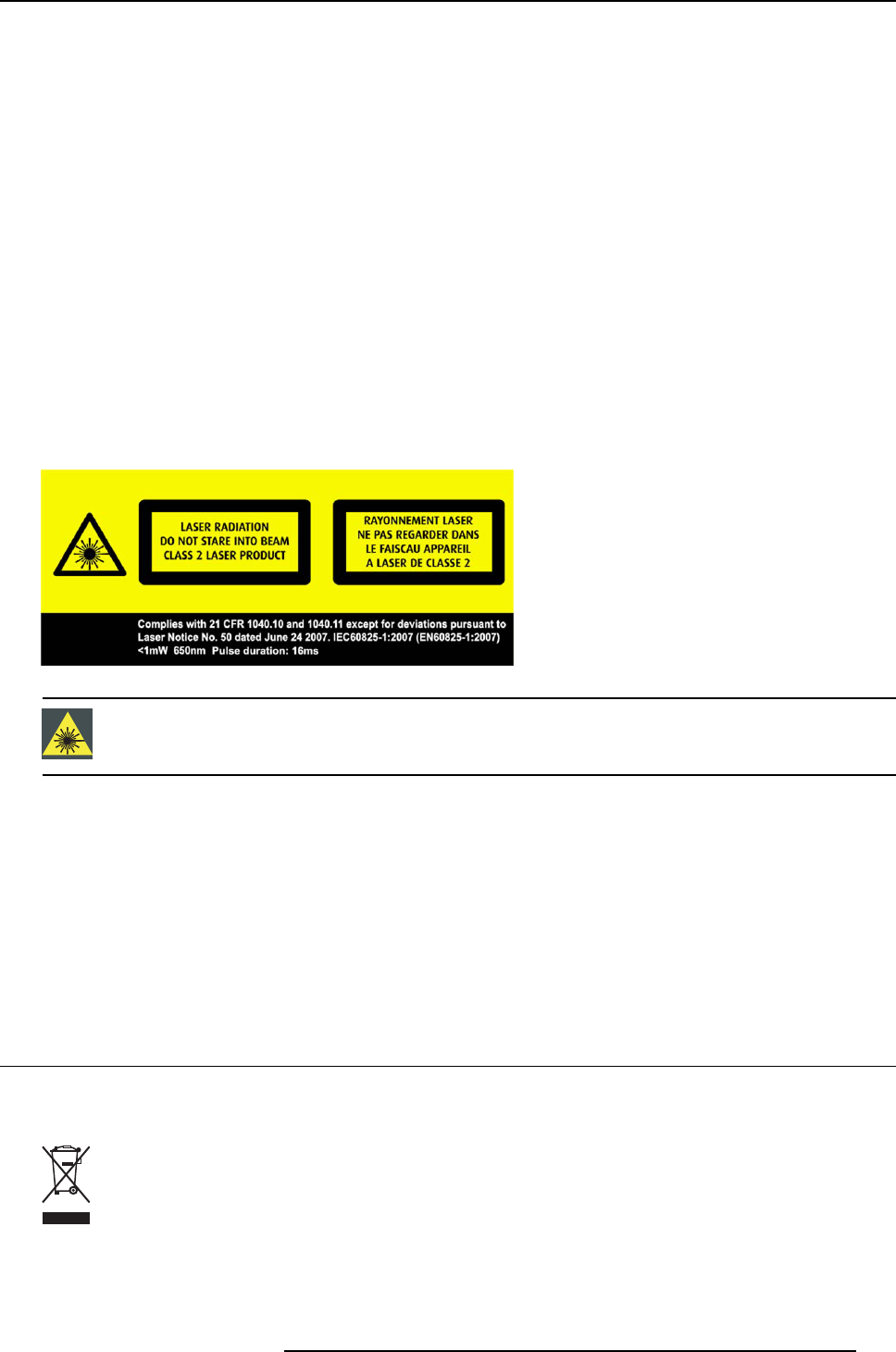
Laser radiation
WARNING:Use of controls or adjustments or performance of procedures other than
those specified herein may result in hazardous radiation exposure.
Ventilation
Do not cover or block any ventilation openings in the cover of the set. When installing the device in a
cupboard or another closed location, heed the necessary space between the set and the sides of the
cupboard.
This apparatus conforms to:
ANSI/AAMI ES 60601-1:2005; CAN/CSA-C22.2 No.60601-1:08; FCC-Class A; CE
5.2 Environmental information
Disposal Information
Waste Electrical and Electronic Equipment
This symbol on the product indicates that, under the European Directive 2012/19/EU governing
waste from electrical and electronic equipment, this product must not be disposed of with other municipal
waste. Please dispose of your waste equipment by handing it over to a designated collection point for the
recycling of waste electrical and electronic equipment. To prevent possible harm to the environment or
K5903077 ST-185C 28/11/2013 19
5. Important information
human health from uncontrolled waste disposal, please separate these items from other types of waste
and recycle them responsibly to promote the sustainable reuse of material resources.
For more information about recycling of this product, please contact your local city office or your municipal
waste disposal service. For details, please visit the Barco website at: http://www.barco.com/en/About-
Barco/weee
Disposal of batteries in the product
This product contains batteries covered by the Directive 2006/66/EC which must be collected and
disposed of separately from municipal waste.
If the battery contains more than the specified values of lead (Pb), mercury (Hg) or cadmium (Cd), these
chemical symbols will appear below the crossed-out wheeled bin symbol.
By participating in separate collection of batteries, you will help to ensure proper disposal and to prevent
potential negative effects on the environment and human health.
Turkey RoHS compliance
Türkiye Cumhuriyeti: AEEE Yönetmeliğine Uygundur.
[Republic of Turkey: In conformity with the WEEE Regulation]
中国大陆RoHS
Chinese Mainland RoHS
根据中国大陆《电子信息产品污染控制管理办法》(也称为中国大陆RoHS), 以下部分列出了Barco产品
中可能包含的有毒和/或有害物质的名称和含量。中国大陆RoHS指令包含在中国信息产业部MCV标准:
“电子信息产品中有毒物质的限量要求”中。
According to the “China Administration on Control of Pollution Caused by Electronic Information Products”
(Also called RoHS of Chinese Mainland), the table below lists the names and contents of toxic and/or
hazardous substances that Barco’s product may contain. The RoHS of Chinese Mainland is included in
the MCV standard of the Ministry of Information Industry of China, in the section “Limit Requirements of
toxic substances in Electronic Information Products”.
零件项目(名称)
Component name
有毒有害物质或元素
Hazardous substances and elements
铅
Pb
汞
Hg
镉
Cd
六价铬
Cr6+
多溴联苯
PBB
多溴二苯
醚
PBDE
印制电路配件
Printed Circuit Assemblies
xooo oo
外接电(线)缆
External Cables
xooo oo
內部线路
Internal wiring
oo oo oo
塑胶外壳
Plastic enclosure
oo oo oo
电源供应器
Power Supply Unit
xooo oo
20 K5903077 ST-185C 28/11/2013
5. Important information
零件项目(名称)
Component name
有毒有害物质或元素
Hazardous substances and elements
铅
Pb
汞
Hg
镉
Cd
六价铬
Cr6+
多溴联苯
PBB
多溴二苯
醚
PBDE
风扇
Fan
oo oo oo
文件说明书
Paper Manuals
oo oo oo
光盘说明书
CD manual
oo oo oo
O: 表示该有毒有害物质在该部件所有均质材料中的含量均在 SJ/T 11363-2006 标准规定的限量要求以下.
O: Indicates that this toxic or hazardous substance contained in all of the homogeneous materials for
this part is below the limit requirement in SJ/T11363-2006.
X: 表示该有毒有害物质至少在该部件的某一均质材料中的含量超出 SJ/T 11363-2006 标准规定的
限量要求.
X: Indicates that this toxic or hazardous substance contained in at least one of the homogeneous
materials used for this part is above the limit requirement in SJ/T11363-2006
在中国大陆销售的相应电子信息产品(EIP)都必须遵照中国大陆《电子信息产品污染控制标识要求》标准
贴上环保使用期限(EFUP)标签。Barco产品所采用的EFUP标签(请参阅实例,徽标内部的编号使用于制
定产品)基于中国大陆的《电子信息产品环保使用期限通则》标准。
All Electronic Information Products (EIP) that are sold within Chinese Mainland must comply with the
“Electronic Information Products Pollution Control Labeling Standard” of Chinese Mainland, marked with
the Environmental Friendly Use Period (EFUP) logo. The number inside the EFUP logo that Barco uses
(please refer to the photo) is based on the “Standard of Electronic Information Products Environmental
Friendly Use Period” of Chinese Mainland.
10
5.3 Regulatory compliance information
Indications for use
The ST-185C is not intended to be used in patient monitoring, diagnosis, treatment, alleviation or preven-
tion of diseases, injuries and handicaps.
RF exposure warning
This equipment must be installed and operated in accordance with provided instructions and the an-
tenna(s) used for this transmitter must be installed to provide a separation distance of at least 20 cm
from all persons and must not be co-located or operating in conjunction with any other antenna or trans-
K5903077 ST-185C 28/11/2013 21
5. Important information
mitter. End-users and installers must be provided with antenna installation instructions and transmitter
operating conditions for satisfying RF exposure compliance.
FCC class A
This equipment has been tested and found to comply with the limits for a Class A digital device, pursuant
to part 15 of the FCC Rules. These limits are designed to provide reasonable protection against harmful
interference when the equipment is operated in a commercial environment. This equipment generates,
uses, and can radiate radio frequency energy and, if not installed and used in accordance with the instruc-
tion manual, may cause harmful interference to radio communications. Operation of this equipment in a
residential area is likely to cause harmful interference in which case the user will be required to correct
the interference at his own expense.
5.4 EMC notice
General information
No specific requirement on the use of external cables or other accessories except power supply.
With the installation of the device, use only the delivered power supply or a spare part provided by the
legal manufacturer. Using another can result in a decrease of the immunity level of the device.
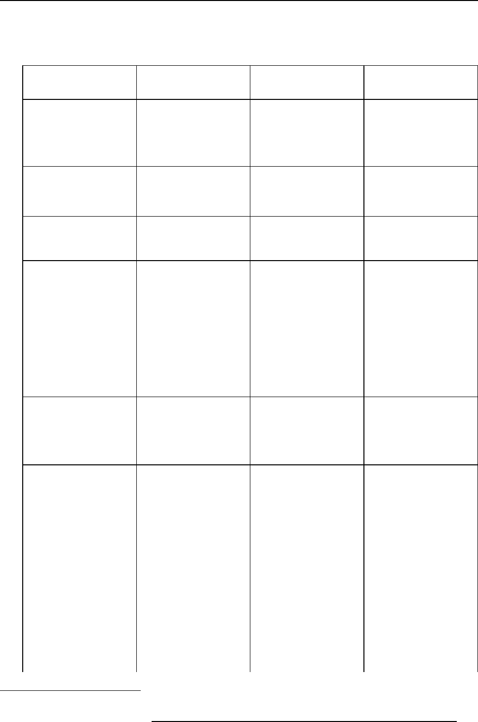
Electromagnetic emissions
The ST-185C is intended for use in the electromagnetic environment specified below. The customer or
the user of the ST-185C should assure that it is used in such an environment.
Emissions test Compliance Electromagnetic environment –
Guidance
RF emissions
CISPR 11
Group 1 The ST-185C uses RF energy
only for its internal function.
Therefore, its RF emissions are
very low and are not likely to
cause any interference in nearby
electronic equipment.
RF emissions
CISPR 11
Class A
Harmonic emissions
IEC 61000-3-2
Class D
Voltage fluctuations/ flicker
emissions
IEC 61000-3-3
Complies
The ST-185C is suitable for use
in all establishments, including
domestic establishments and
those directly connected to the
public low-voltage power supply
network that supplies buildings
used for domestic purposes.
This ST-185C complies with appropriate medical EMC standards on emissions to, and interference from
surrounding equipment. Operation is subject to the following two conditions: (1) this device may not cause
harmful interference, and (2) this device must accept any interference received, including interference that
may cause undesired operation.
Interference can be determined by turning the equipment off and on.
If this equipment does cause harmful interference to, or suffer from harmful interference of, surrounding
equipment, the user is encouraged to try to correct the interference by one or more of the following mea-
sures:
• Reorient or relocate the receiving antenna or equipment.
• Increase the separation between the equipment and receiver.
• Connect the equipment into an outlet on a circuit different from that to which the receiver is connected.
• Consult the dealer or an experienced technician for help.
22 K5903077 ST-185C 28/11/2013
5. Important information
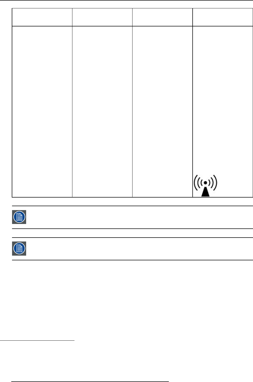
Electromagnetic immunity
The ST-185C is intended for use in the electromagnetic environment specified below. The customer or
the user of the ST-185C should assure that it is used in such an environment.
Immunity test IEC 60601
Test levels
Compliance level Electromagnetic
environment –
guidance
Electrostatic discharge
(ESD)
IEC 61000-4-2
± 6kV contact
±8kVair
± 6kV contact
±8kVair
Floors should be wood,
concrete or ceramic tile.
If floors are covered with
synthetic material, the
relative humidity should
be at least 30%
Electrical fast
transient/burst
IEC 61000-4-4
± 2kV for power supply
lines
± 1kV for input/ output
lines
± 2kV for power supply
lines
± 1kV for input/ output
lines
Mains power quality
should be that of a typical
commercial or hospital
environment
Surge
IEC61000-4-5
± 1 kV line(s) to line(s)
± 2 kV line(s) to earth
± 1 kV line(s) to line(s)
±2kVline(s)toearth
Mains power quality
should be that of a typical
commercial or hospital
environment
Voltage dips, short
interruptions and voltage
variations on power
supply input lines
IEC 61000-4-11
<5%U
T1(> 95% dip in
UT) for 0.5 cycle
40% UT(60%dipinU
T)
for 5 cycles
70% UT(30%dipinU
T)
for 25 cycles
<5%U
T(>95% dip in
UT) for 5s
<5%U
T(> 95% dip in
UT) for 0.5 cycle
40% UT(60% dip in UT)
for 5 cycles
70% UT(30% dip in UT)
for 25 cycles
<5%U
T(>95% dip in
UT)for5s
Mains power quality
should by that of a typical
commercial or hospital
environment. If the
user of the ST-185C
requires continued
operation during power
mains interruptions, it is
recommended that the
ST-185C be powered
from an uninterruptible
power supply or a battery.
Power frequency (50/60
Hz) magnetic field
IEC 61000-4-8
3A/m Not applicable Power frequency
magnetic fields should
be at levels characteristic
of a typical location in
a typical commercial or
hospital environment.
Conducted RF
IEC 61000-4-6
Radiated RF
IEC 61000-4-3
3Vrms
150 kHz to 80 MHz
3V/m
80 MHz to 2.5 GHz
3V
3V/m
Portable and mobile
RF communications
equipment should be
used no closer to any
part of the ST-185C,
including cables, than
the recommended
separation distance
calculated from the
equation applicable
to the frequency
of the transmitter.
Recommended
separation distance
d=1.2√P
d=1.2√P80 MHz to 800
MHz
1. is the a.c. mains voltage prior to application of the test level.
K5903077 ST-185C 28/11/2013 23
5. Important information
Immunity test IEC 60601
Test levels
Compliance level Electromagnetic
environment –
guidance
d=2.3√P800 MHz to 2.5
Ghz
Where P is the maximum
output power rating
of the transmitter in
watts (W) according
to the transmitter
manufacturer and d
is the recommended
separation distance in
meters (m).
Field strengths from
fixed RF transmitters,
as determined by an
electromagnetic site
survey,2should be less
than the compliance
level in each frequency
range.3
Interference may occur in
the vicinity of equipment
marked with symbol:
At 80 MHz and 800 MHz, the higher frequency range applies.
These guidelines may not apply in all situations. Electromagnetic propagation is af-
fected by absorption and reflection from structures, objects and people.
Recommended separation distance
The ST-185C is intended for use in an electromagnetic environment in which radiated RF disturbances
are controlled. The customer of the user of the ST-185C can help prevent electromagnetic interference
by maintaining a minimum distance between portable and mobile RF communications equipment (trans-
mitters) and the ST-185C as recommended below, according to the maximum output power of the com-
munications equipment.
2. Field strengths from fixed transmitters, such as base stations for radio (cellular/cordless) telephones and land mobile radios, amateur
radio, AM and FM radio broadcast and TV broadcast cannot be predicted theoretically with accuracy. To assess the electromagnetic
environment due to fixed RF transmitters, an electromagnetic site survey should be considered. If the measured field strength in the
location in which the ST-185C is used exceeds the applicable RF compliance level above, the ST-185C should be observed to verify
normal operation. If abnormal performance is observed, additional measures may be necessary, such as re-orienting or relocating
the ST-185C.
3. Over the frequency range 150 kHz to 80 MHz, field strengths should be less than3V/m.
24 K5903077 ST-185C 28/11/2013
5. Important information
Separation distance according to frequency of transmitter
Rated maximum output
power of transmitter 4
W
150kHz to 80MHz
d=1.2√P
80MHz to 800MHz
d=1.2√P
800MHz to 2.5GHz
d=2.3√P
0.01 0.12 0.12 0.23
0.1 0.38 0.38 0.73
1 1.2 1.2 2.3
10 3.8 3.8 7.3
100121223
At 80 MHz and 800 MHz, the separation distance for the higher frequency range applies.
These guidelines may not apply in all situations. Electromagnetic propagation is af-
fected by absorption and reflection form structures, object and people.
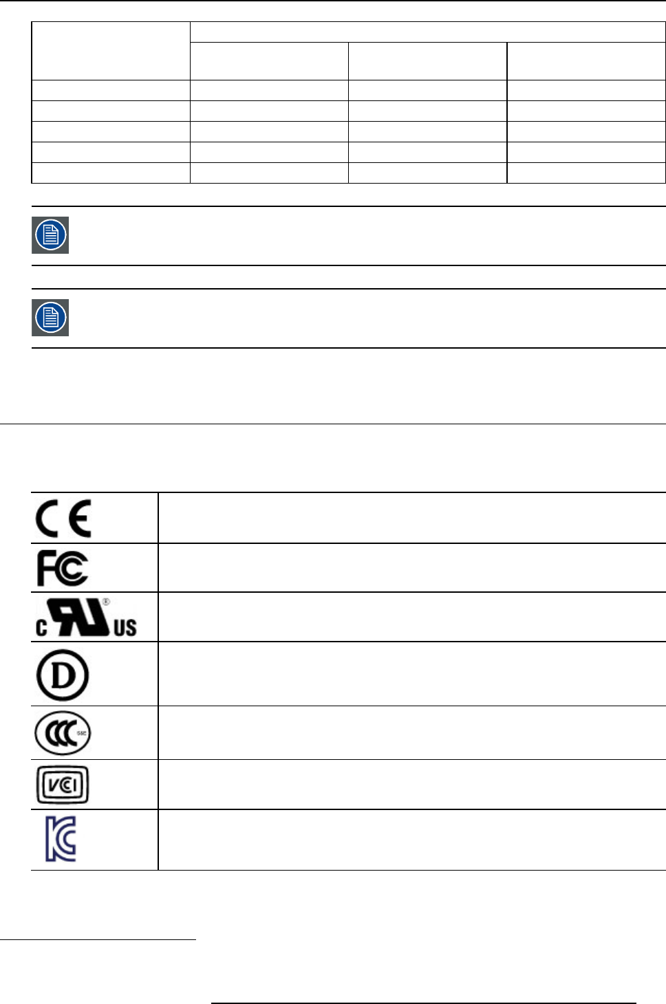
5.5 Explanation of symbols
Symbols on the device
On the device or power supply, you may find the following symbols (nonrestrictive list):
Indicates the device meets the requirements of the applicable EC directives.
Indicates compliance with Part 15 of the FCC rules (Class A or Class B)
Indicates the device is approved according to the UL Recognition regulations
Indicates the device is approved according to the UL Demko regulations
Indicates the device is approved according to the CCC regulations
Indicates the device is approved according to the VCCI regulations
Indicates the device is approved according to the KC regulations
4. For transmitters rated at a maximum output power not listed above, the recommended separation distance d in meters (m) can be
estimated using the equation applicable to the frequency of the transmitter. Where P is the maximum output power rating of the
transmitter in watts (W) according to the transmitter manufacturer.
K5903077 ST-185C 28/11/2013 25
5. Important information
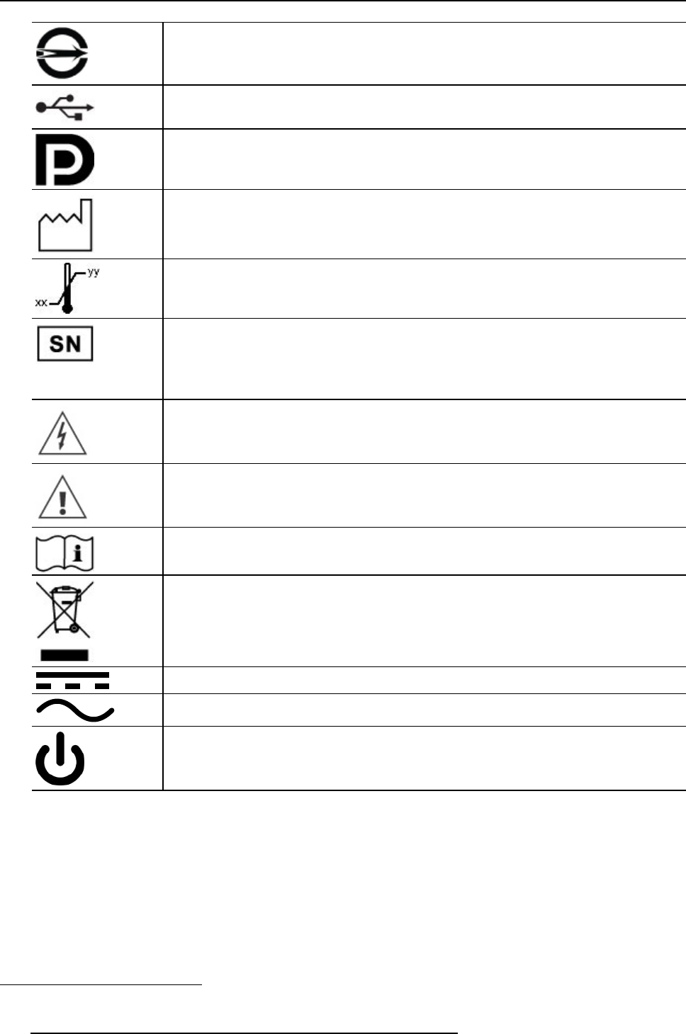
Indicates the device is approved according to the BSMI regulations
Indicates the USB connectors on the device
Indicates the DisplayPort connectors on the device
Indicates the manufacturing date
Indicates the temperature limitations5for the device to safely operate within specs.
Indicates the device serial no
Warning: dangerous voltage
Caution
Consult the operating instructions
Indicates this device must not be thrown in the trash but must be recycled,
according to the European WEEE (Waste Electrical and Electronic Equipment)
directive
Indicates Direct Current (DC)
Indicates Alternating Current (AC)
Stand-by
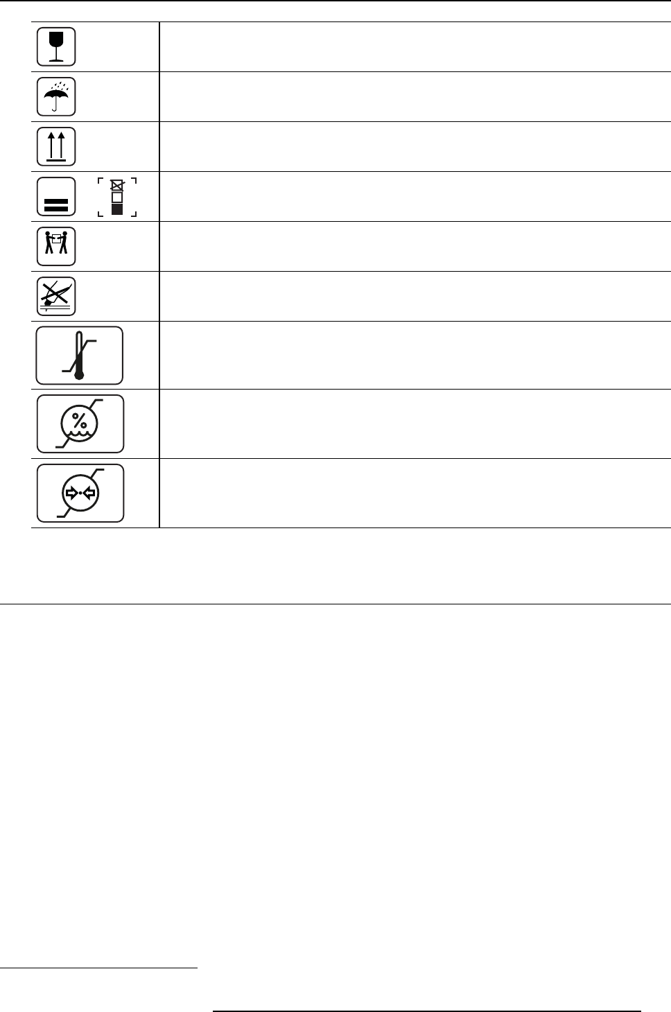
Symbols on the box
On the box of the device, you may find the following symbols (nonrestrictive list):
5. Values for xx and yy can be found in the technical specifications paragraph.
26 K5903077 ST-185C 28/11/2013
5. Important information
Indicates a device that can be broken or damaged if not handled carefully when
being stored.
Indicates a device that needs to be protected from moisture when being stored.
Indicates the storage direction of the box. The box must be transported, handled
and stored in such a way that the arrows always point upwards.
15
or
n
Indicates the maximum number of identical boxes which may be stacked on each
other, where “n” is the limiting number.
20 - 30 Kg
Indicates that the box should be carried with two persons.
Indicates that the box should not be cut with a knife, a cutter or any other sharp
object.
-20 °C
+60 °C
xx
yy
Indicates the temperature limits6to which the device can be safely exposed when
being stored.
85 %
5 %
x
yy Indicates the range6of humidity to which the device can be safely exposed when
being stored.
106 kPa
50 kPa
xx
yyy Indicates the range6of atmospheric pressure to which the device can be safely
exposed when being stored.
5.6 Legal disclaimer
Disclaimer notice
Although every attempt has been made to achieve technical accuracy in this document, we assume no
responsibility for errors that may be found. Our goal is to provide you with the most accurate and usable
documentation possible; if you discover errors, please let us know.
Barco software products are the property of Barco. They are distributed under copyright by Barco N.V. or
Barco, Inc., for use only under the specific terms of a software license agreement between Barco N.V. or
Barco Inc. and the licensee. No other use, duplication, or disclosure of a Barco software product, in any
form, is authorized.
The specifications of Barco products are subject to change without notice.
Trademarks
All trademarks and registered trademarks are property of their respective owners.
Copyright notice
This document is copyrighted. All rights are reserved. Neither this document, nor any part of it, may
be reproduced or copied in any form or by any means - graphical, electronic, or mechanical including
photocopying, taping or information storage and retrieval systems - without written permission of Barco.
6. Values for xx and yy can be found in the technical specifications paragraph.
K5903077 ST-185C 28/11/2013 27
5. Important information
© 2013 Barco N.V. All rights reserved.
5.7 Technical specifications
Technical specifications for the ST-185C
Display LED, 18.5" WXGA (1366 x 768)
Processor Intel Atom Cedar Trail D2550 - 1.86 GHz
System chip set Intel NM10
BIOS AMI 16M-bit SPI UFEI BIOS
RTC battery CR2032
Storage Optional 2.5” HDD or SSD (Standard - no storage installed)
Required rating: 5Vdc, max 2A
HDD drive 320 GB (optional)
SSD drive 8, 16, or 32 GB (optional)
System memory DDR3 1066
2or4GB
Operating system Linux
Windows® XP Embedded
Windows® XP Professional for Embedded Systems
Windows® 7 Embedded
Connectivity LAN (x1)
USB 2.0 (x4)
Headphone jack (x2)
Microphone jack (x1)
Handset connector
DVI-I out
Programmable GPIO
Service Call (optional)
User interface 5-wire resistive touch-screen
On screen keyboard
Membrane keypad
On/Off switch
LED call warning lights
Webcam Integrated, with privacy shutter
HD720P
Audio 2 off 2 Watt integral speakers
Internal microphone
Warning / ring tones
28 K5903077 ST-185C 28/11/2013
5. Important information
Medical Environment
Consideration
Antibacterial coating
Fanless cooling
Certifications ANSI/AAMI ES 60601-1:2005; CAN/CSA-C22.2 No.60601-1:08;
FCC-Class A; CE
Power requirements 19V DC, 4.74A
Device is intended to be supplied with a PSU with rated output of 19V,
4.74A,
Dimensions (mm) 456 x 339 x 67 (without handset, external SCR (Smart Card Reader))
Weight 5.5 kg
Internal options
Smart Card Reader (SCR) √
Combined SCR and RFID
reader
√
WiFi Mini PCe 802.11b/g/n Wireless LAN Module
Bluetooth USB Bluetooth Module
Service call √
BarCode Scanner (BCS) 2D
External options
Analogue handset √
External SCR (Smart Card
Reader)
√
Wired remote (RIMO) √
Operating temperature 0°C to 40°C
Storage & transport
temperature
-20°C to 60°C
Operating humidity 20% - 90% (non-condensing)
Storage & transport humidity 10% - 80% (non-condensing)
Operating atmospheric
pressure
50 - 106 kPa
Storage and transport
atmospheric pressure
50 - 106 kPa
K5903077 ST-185C 28/11/2013 29