Bard Dc3003 2100 484(E) (2011 08) User Manual To The D2f73565 F22f 4022 B61c 840a8053e1c9
User Manual: Bard Dc3003 to the manual
Open the PDF directly: View PDF ![]() .
.
Page Count: 22
Manual 2100-484E
Page 1 of 22
DC3002 and DC3003 SOLID STATE
LEAD/LAG CONTROLLER
with DC FAN CONTROL
INSTALLATION INSTRUCTIONS
& REPLACEMENT PARTS LIST
Manual No.: 2100-484E
Supersedes: 2100-484D
File: Vol. III Tab 19
Date: 08-29-11
Bard Manufacturing Company, Inc.
Bryan, Ohio 43506
Since 1914...Moving ahead, just as planned.

Manual 2100-484E
Page 2 of 22
CONTENTS
Getting Other Information and Publications 3
DC3000 General Information
Shipping Damage .................................................. 4
General .................................................................. 4
Theory of Operation ............................................... 4
Controller Certifications ......................................... 4
Specifications/Features for Basic Controller
DC3000 Basic Controller ....................................... 5
Mounting the Controller
Installation Instructions .......................................... 5
Temperature Sensors
Remote Indoor Sensor........................................... 5
Remote Outdoor Sensor ........................................ 5
Temperature Sensor Logic
Using Multiple Sensors .......................................... 5
Controller Input/Output Specifications
Main Controller Board ............................................ 6
Internal Alarm Board .............................................. 6
Low Voltage Field Wiring
Circuitry in the DC3000.......................................... 7
Controller Grounding
Earth ground .......................................................... 7
Controller Power-Up
Time Delay on Power-Up ....................................... 7
Fire Suppression Circuit
Disabling the DC3000 ............................................ 7
Staging Delay Periods
Stages 1 - 4............................................................ 7
Blower Operation
Various Blower Options ......................................... 7
Advance (Swap) Lead/Lag Unit Feature
Manual Switching of Units ..................................... 7
Accelerate Timer Feature
Testing the Timer Function..................................... 7
Humidity Control Option
Adding Optional Humidity Control.......................... 8
Sequence of Operation - Cooling (Air Conditioners)
No Economizer ...................................................... 8
With Economizers.................................................. 8
Sequence of Operation - Heating (Air Conditioners)
With Electric Heat .................................................. 9
Figures
Figure 1 DC3002 Controller Connections for 2 Air
Conditioners with Economizer ................... 11
Figure 2 DC3002 Controller Connections for 2 Air
Conditioners with No Economizer.............. 12
Figure 3 DC3003 Controller Connections for 3 Air
Conditioners with 3 Economizers .............. 13
Figure 4 DC3003 Controller Connections for 3 Air
Conditioners with Economizers
(No Economizer A/C #3)......................... 14
Figure 5 DC3003 Controller Connections for 3 Air
Conditioners with No Economizers ............ 15
Figure 6 Alarm Board Connections for Normally Closed
“NC” Open-On-Alarm Strategy ................... 17
Figure 7 Alarm Board Connections for Normally
Open “NO” Close-On-Alarm Strategy ..... 18
(Label) DC3000 Series ....................................... 20
Figure 8 Parts List Description ............................. 21
Tables
Table 1 Controller Connection Diagrams ............ 10
Table 2 Parts List ................................................ 22
Security (Locking) Feature
Locking and Unlocking the DC3000 ...................... 9
Generator Run Feature
Standby Generator Disable Operation ................... 9
Backup DC Power Connection
Input Connections Available .................................. 9
DC Fan Control
Free Cooling & Emergency Ventilation ................ 10
Shelter Purge Control .......................................... 10
Controller Wiring
Refer to Connection Diagram ...................... 10 & 11
Alarm Wiring
Wiring Alarm Relays ............................................ 16
2nd Stage Cooling Alarm
Alarm Output is Available..................................... 16
Refrigerant Pressure Alarms
Connecting the Alarm Circuit ............................... 16
Emergency Ventilation Sequence
Using Economizers
Two Operating Sequences .................................. 16
Programming Instructions ................................... 19

Manual 2100-484E
Page 3 of 22
Getting Other Information and Publications
These publications can help you install the air
conditioner or heat pump. You can usually find these at
your local library or purchase them directly from the
publisher. Be sure to consult current edition of each
standard.
Standard for the Installation .............. ANSI/NFPA 90A
of Air Conditioning and
Ventilating Systems
Standard for Warm Air Heating ........ ANSI/NFPA 90B
and Air Conditioning Systems
FOR MORE INFORMATION, CONTACT
THESE PUBLISHERS:
ACCA Air Conditioning Contractors of America
1712 New Hampshire Avenue, NW
Washington, DC 20009
Telephone: (202) 483-9370
Fax: (202) 234-4721
ANSI American National Standards Institute
11 West Street, 13th Floor
New York, NY 10036
Telephone: (212) 642-4900
Fax: (212) 302-1286
ASHRAE American Society of Heating, Refrigerating,
and Air Conditioning Engineers, Inc.
1791 Tullie Circle, N.E.
Atlanta, GA 30329-2305
Telephone: (404) 636-8400
Fax: (404) 321-5478
BARD Bard Manufacturing Company, Inc.
1914 Randolph Drive
Bryan, OH 43506
Telephone: (419) 636-1194
Fax: (419) 636-2640

Manual 2100-484E
Page 4 of 22
SHIPPING DAMAGE
Upon receipt of equipment, the carton should be checked
for external signs of shipping damage. If damage is
found, the receiving party must contact the last carrier
immediately, preferably in writing, requesting inspection
by the carrier’s agent.
GENERAL
NOTE: DC3000 is used throughout this Manual as a
general reference to the controller system. There are
two controller models, DC3002 for 2 HVAC units and
DC3003 for 3 HVAC units, and these model numbers
are referenced when specific features or characteristics
apply only to either the DC3002 or the DC3003.
Occasional reference is made to alarm board AB3002 or
AB3003. AB3002 is the internal alarm board for the
DC3002 controller, and AB3003 is the internal alarm
board for the DC3003 controller.
These instructions explain the operation, installation and
troubleshooting of the DC3000 controller.
All internal wiring is complete. Only attach low voltage
field wiring to designated terminal strips.
The DC3000 is for use with units with or without
economizers, and has a dehumidification control feature
if an optional humidity controller is connected.
Each unit should be sized to handle the total load of the
structure if 100% redundancy is required.
It is recommended that a five (5) minute compressor
time delay relay be installed in each unit.
The DC3000 controllers are suitable for both 50 and 60
HZ operation, and are fully configurable such that they
can be used in virtually any installation. See Controller
Programmable Features and Default Settings.
THEORY OF OPERATION
The DC3002 controller is used to control two wall
mount air conditioners from one control system. It
provides total redundancy for the structure and equal
wear on both units. It can be used with units with or
without economizers and it is recommended that both
units be equipped alike.
The DC3003 controller is designed to control 3 air
conditioners, and can be used for 2 if it is anticipated the
third unit may be installed later.
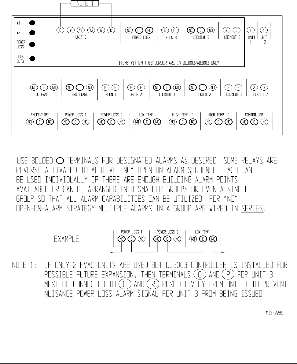
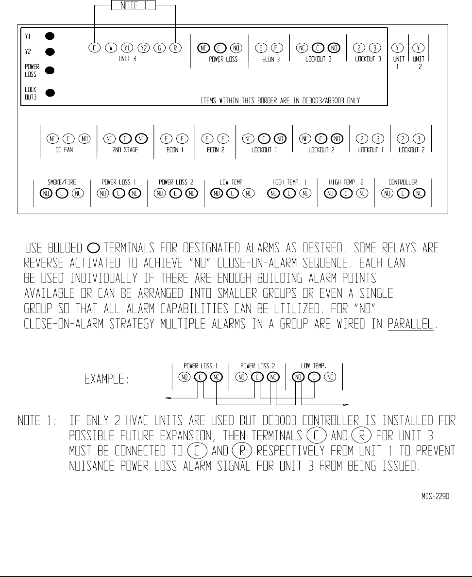
NOTE: If this is done, see Note 1 on Alarm Board
Connections (Figure 6 or 7) to prevent nuisance Power
Loss Alarm indication for absent HVAC #3
When DC3003 is used for controlling three HVAC
units, only units 1 or 2 operate in lead/lag sequence.
HVAC #3 is always last to operate and functions only in
the number 3 position. All three units are available to
operate on-demand as required.
Alarm capability is standard on both models.
CONTROLLER CERTIFICATIONS
The DC3000 main controller board, optional alarm
boards, and remote sensors have undergone extensive
testing for immunity and emissions. This system is
FCC-compliant, in accordance with CE requirements,
and meets the following standards:
EN50082-2 Standard for Immunity
EN55011 Standard for Emissions
** IMPORTANT **
The equipment covered in this manual is to be installed by
trained, experienced service and installation technicians.
Please read entire manual before proceeding.

Manual 2100-484E
Page 5 of 22
SPECIFICATIONS/FEATURES FOR
BASIC CONTROLLER
DC3000 Basic Controller
•Input power: 18 to 32VAC, 60/50Hz, power is supplied
from A/C #1 and/or A/C #2
•Isolation circuitry: no line or low voltage phasing
required
•Backup power: connection for -24VDC or -48VDC
(-20 to -56V) maintains microprocessor operation, front
panel indication, and alarm relay operation during
commercial power outages.
•Digital display: 4-character LCD
•Temperature display: F or C
•HVAC outputs: Form A (NO) relays (1A @ 24VAC)
•Cooling control stages: 2 for each A/C unit
•Heating Control stages: 1 for each A/C unit
•Dehumidification circuit: requires optional humidity
controller as input signal.
•Operating temperature range: 0 to 120F (-18 to 49C)
•Storage temperature range: -20 to 140F (-29 to 60C)
•Temperature accuracy: +/- 1F from 60-85F (16-30C)
+/- 1% outside 60-85F
•Lead/lag changeover time: 0 to 30 days
•Timing accuracy: +/- 1%
•Inter-stage time delay: 10 seconds between stages
•Inter-stage differential: 2F (1C) for all modes
•On-Off differential: 2F (1C) is standard, 4F (3C) when
“excessive cycling” mode is enabled.
•Cooling set point range: 65 to 90F (18 to 32C)
•Comfort setting-Cooling 72F (22C), Heating 68F(20C),
for 1 hour.
•Dead band (difference between cooling and heating set
points): 2F to 20F (1C to 10C)
•Fire/smoke interface: standard NC circuit jumper, remove
for connection to building system control, shuts down both
A/C units immediately.
•Memory: EEPROM for set point and changeable
parameters (maintains settings on power loss).
•Temperature sensors: 1 local is standard, will accept up to
2 optional 25-foot remote sensors, Bard part number
8612-023. One can be used for remote indoor sensor and
one is dedicated for outdoor sensor for DC Fan free
cooling operation, if desired.
•Controller Enclosure: 20-gauge pre-painted steel, 9.25"W
x 13.50"H x 3.00"D, hinged cover, thirteen (13) .875"
diameter electrical knockouts.
•LEDs for basic controller: Lead unit, Cooling stages 1
through 4, Heating Stages 1 through 4, Dehumidification
operation. DC3003 has cooling stage and alarm LED’s
displayed internally for HVAC #3.
•Six (6) Push-button controls: On/Off switch-Change lead
unit-Increase and Decrease set points-Program/Save-
Comfort.
MOUNTING THE CONTROLLER
Included in the controller carton is the controller and
installation instructions.
The controller should be installed on a vertical wall
approximately four (4) feet above the floor - away
from drafts and outside doors or windows. Four (4)
mounting holes are provided for mounting to the wall,
and 7/8" holes for conduit connections are provided in
both the base, sides and top of the controller.
TEMPERATURE SENSORS
The standard (local) temperature sensor has 12" leads
and comes installed from the factory.
The controller is designed to accept 1 additional
remote indoor sensor, and connects to “Rem 1”. The
Bard part number for the optional sensor with 25-foot
leads is 8612-023. This remote indoor sensor can be
installed as required in the structure to address hot
spots, barriers to airflow, etc. It can also be used as
the local sensor
Outdoor sensor, same 8612-023 with 25-foot leads, is
required for non-economizer installations when DC
fan is to be used for free cooling. This sensor
connects to the “Out” terminals.
It is recommended that the sensor lead wires be
installed in conduit for protective purposes.
The highest reading of any connected indoor sensor
will be used for high temperature alarm and the lowest
reading sensor will be used for low temperature alarm.
TEMPERATURE SENSOR LOGIC
The standard local (Loc) sensor monitors the
temperature at the controller location. If this is the
only sensor connected, it will control the temperature
read-out, the space (building) temperature, and also be
used for Low and High Temperature alarm functions.
If one REMOTE sensor is installed and connected
(Rem 1), the temperature read-out will display and the
building will be controlled to an average of connected
sensors. If there is more than 10F difference from the
highest to the lowest connected sensor, the actual
control will be governed by the hottest sensor for
cooling and the coldest sensor for heating.
If two indoor temperature sensors are used, the
average of the two sensors becomes the controller
cooling and testing set point.
NOTE: All sensors are polarity sensitive. The
copper lead must connect to terminal CU,
and the silver lead to AG.
Sensors are solid state, not RTD.
Use only sensors supplied by Bard.

Manual 2100-484E
Page 6 of 22
Note: All alarm relays are dry contacts rated 1A @
24VAC, 120VAC or 150VDC.
DC3002/3003 CONTROLLER CONNECTIONS
Located on Main Controller Board
Unit #1 C – 24VAC common
R – 24VAC hot
G – fan (Form A, NO)
Y1 – 1st-stage cool (Form A, NO)
Y2 – 2nd-stage cool (Form A, NO)
W – heat (Form A, NO)
Unit #2 C – 24VAC common
R – 24VAC hot
G – fan (Form A, NO)
Y1 – 1st-stage cool (Form A, NO)
Y2 – 2nd-stage cool (Form A, NO)
W – heat (Form A, NO)
Unit #3 C – 24VAC common
(DC3003 only R – 24VAC hot
and located on G – fan (Form A, NO)
Internal Alarm Y1 – 1st-stage cool (Form A, NO)
Board) Y2 – 2nd-stage cool (Form A, NO)
W – heat (Form A, NO)
F1-F2 Fire/smoke interface
Shipped with jumper installed (a)
48Vdc Back-up power input
-24Vdc or –48Vdc
-20V to –56V range
Local Main sensor, 12-inch leads
CU – copper, AG – silver
Polarity sensitive
Rem 1 Optional remote indoor sensor
CU – copper, AG – silver
Polarity sensitive
Out Optional outdoor sensor (b)
CU – copper, AG – silver
Polarity sensitive
Gen Generator interface G1-G2
Shipped with jumper installed (a)
H1-H2 Humidity controller input
Requires optional controller
Field installed
(a) These connections require either jumper or Normally
Closed (NC) relay contact at the Fire/Smoke and Generator
interface for Controller to function.
(b) Required connection if field installed DC Fan is to be used
for free cooling and no economizers are installed in HVAC
units.
DC3002/3003 CONTROLLER CONNECTIONS
Located on Internal Alarm Board AB3002
DC3002 Inputs
Lockout 1 2,3 – input from HVAC #1
Lockout 2 2, 3 – input from HVAC #2
Y Unit 1 signals when comp. #1 is active
Y Unit 2 signals when comp. #2 is active
DC3002 Alarm Outputs
Smoke/Fire Form C (SPDT)
Lockout 1 Form C (SPDT)
Refrigerant alarm HVAC #1
Lockout 2 Form C (SPDT)
Refrigerant alarm HVAC #2
Power Loss 1 Form C (SPDT)
Power loss HVAC #1
Power Loss 2 Form C (SPDT)
Power loss HVAC #2
Low Temp Form C (SPDT)
Low temperature alarm
High Temp 1 Form C (SPDT)
High temperature alarm #1
High Temp 2 Form C (SPDT)
High temperature alarm #2
Controller Form C (SPDT)
Controller failure alarm
DC3002 Control Outputs
Econ 1 E, F - Form A (NO)
See note (c )
Econ 2 E, F - Form A (NO)
See note (c )
DC Fan Form C (SPDT)
Pilot relay for DC Fan control
2nd Stage Form C (SPDT)
2nd-stage cooling alarm
(c ) Make these connections to terminals E & F in HVAC 1
and 2 respectively if desired to have economizers open for
emergency ventilation at High Temp Alarm #2 setpoint
condition.
DC3003 Inputs
Everything from DC3002 plus:
Lockout 3 2,3 – input from HVAC #3
DC3003 Alarm Outputs (on AB3003 Internal Alarm Board)
Everything from DC3002 plus:
Lockout 3 Form C (SPDT)
Refrigerant alarm HVAC # 3
Power Loss 3 Form C (SPDT)
Power loss HVAC #3
DC3003 Control Outputs
Econ 3 E, F - Form A (NO)
See note (c )
CONTROLLER INPUT/OUTPUT SPECIFICATIONS
Alarm relays can be wired for NO (close on alarm) or NC (open on alarm) strategy. Alarm relays can be used individually if
there are enough available building alarm points, or can be arranged into smaller groups or even a single group so that all
alarm capabilities can be utilized. When multiple alarms are grouped together and issued as a single alarm there will be no
off-site indication of which specific problem may have occurred, only that one of the alarms in the group has been triggered.
The individual alarm problem will be displayed on the LED display on face of the controller.
NOTE:
Sensors are
solid state,
not RTD.
Use Bard
sensors only.

Manual 2100-484E
Page 7 of 22
LOW VOLTAGE FIELD WIRING
The DC3000 is powered from the air conditioners that it
is controlling, 24VAC (18-32V) low voltage only.
Circuitry in the DC3000 isolates the power supplies of
all connected air conditioners so that no back feeds or
phasing problems can occur. Additionally, if any air
conditioner loses power, the DC3000 and the other air
conditioner are unaffected and will continue to operate
normally.
Connect the low voltage field wiring from each unit per
the low voltage field wiring diagrams in Section on
“Controller Wiring”.
CONTROLLER GROUNDING
A reliable earth ground must be connected in addition to
any grounding from conduit.
CONTROLLER POWER-UP
Whenever power is first applied to the controller, there
is a twenty (20) second time-delay prior to any function
(other than display) becoming active. This time-delay is
in effect if the controller On/Off button is used when
24VAC from air conditioners is present, and also if
controller is in “ON” position and 24VAC from all
connected air conditioners is removed and then restored.
FIRE SUPPRESSION CIRCUIT
To disable the DC3000 and shut down both air
conditioners, terminals F1 and F2 may be used. The F1
and F2 terminals must be jumpered together for normal
operation. A normally closed (nc) set of dry contacts
may be connected across the terminals and the factory
jumper removed for use with a field-installed fire
suppression system. The contacts must open if a fire is
detected. See appropriate connection diagram - Figures
1, 2 or 3 for this connection. Contacts should be rated
for pilot duty operation at 2 amp 24VAC minimum.
Shielded wire (22-gauge minimum) must be used, and
the shield must be grounded to the controller enclosure.
IMPORTANT NOTE: Some Bard models employ an
electronic blower control that has a 60-second blower
off-delay. In order to have immediate shutdown of the
blower motor, in addition to disabling the run function
of the air conditioners will require a simple wiring
modification at the blower control located in the
electrical control panel of the air conditioners being
controlled by the lead/lag controller. To eliminate the
60-second blower off-delay, disconnect and isolate the
wire that is factory-connected to the “R” terminal on the
electronic blower control, and then connect a jumper
from the “G” terminal on the blower control to the “R”
terminal on the blower control. The electronic blower
control will now function as an on-off relay with no off-
delay, and the blower motor will stop running
immediately when the F1-F2 fire suppression circuit is
activated (opened).
STAGING DELAY PERIODS
The following delays are built in for both cooling and
heating:
Stage 1 –
0 seconds for blower (if not already on as
continuous)
10 seconds for cooling or heating output
Stage 2 –
10 seconds after Stage 1 for blower
10 additional seconds for cooling or heating
output
Stage 3 –
10 seconds after Stage 2
Stage 4 –
10 seconds after Stage 3
Note: For cooling Stages 1 and 2, the stage LED will
blink for 10 seconds while the cooling output is delayed
after that stage is called for. There is also a delay after
the stage is satisfied, and after the LED stops blinking,
the stage will turn off. There is a minimum 10-second
delay between stages 2 & 3, and 3 & 4, but no delayed
output when stage is turned on or off, and LED for those
stages will not blink.
BLOWER OPERATION
The controller can be configured to have main HVAC
blowers cycle on and off on demand; have all blowers
run continuously (for DC3003, the blower is not “On”
continuously for HVAC #3, but runs on demand only
condition); or have the lead unit blower run continuously
with the lag unit blower cycling on demand. Lead unit
blower operating continuously is the default setting.
There is also an option to have all blowers cycle on if one
remote sensor is connected, and a temperature difference
of more than 5F between any two sensors is observed.
This helps to redistribute the heat load within the structure
and should reduce compressor operating time.
When any of the stages are satisfied, the stage LED will
blink for ten (10) seconds before the stage is actually
turned off.
ADVANCE (SWAP) LEAD/LAG UNIT
FEATURE
Pressing the Advance button for one (1) second will cause
the lead and lag units to change positions. This may be
useful during service and maintenance procedures.
Note: DC3003 always operates HVAC #3 in last position:
only HVAC #1 and #2 operate in lead/lag sequence.
ACCELERATE TIMER FEATURE
Pressing the UP arrow button for five (5) seconds will
activate an accelerate (speed-up) mode, causing the
normal changeover time increments of days to be
reduced to seconds. Example: 7 days becomes 7
seconds. When “ACC” displays, release button.
Whichever LED is on, indicating lead unit will blink
over for each second until the controller switches. This
is a check for the timer functionality.
Manual 2100-484E
Page 8 of 22
SEQUENCE OF OPERATION – COOLING AIR
CONDITIONERS – (NO ECONOMIZER)
First stage cooling set point is the setting (SP) input into the
controller. Factory default is 75F/24C. At Stage 1 cooling
SP, the blower of the lead unit will come on (if not already
operating because of continuous fan selection for lead unit).
The DC fan will also operate at this time if controller is
configured for free cooling using DC fan, and if outdoor
temperature is 1F or more below (dFon) setting for DC fan
operation 50, 55 or 60F (default is 55). DC fan is off at 1F
above the (dFon) setting.
At Stage 2 cooling call (SP + 2F), the compressor for lead
unit comes on.
At Stage 3 cooling call (SP + 4F), the blower for the lag unit
comes on, followed 10 seconds later by the compressor for
the lag unit.
SEQUENCE OF OPERATION – COOLING AIR
CONDITIONERS – (WITH ECONOMIZERS)
Note: Economizer Logic Enabled must be switched from
No to Yes in the Programming Menu.
First stage cooling set point is the setting (SP) input into the
controller. Factory default is 75F/24C. On a call for 1st Stage
cooling, the blower will come on immediately (if not already
on - See Blower Operation), and the Stage 1 LED will blink for
10 seconds before going solid, at which time the cooling output
turns on. If the outdoor temperature and humidity conditions
are below the set point of the economizer enthalpy control, the
economizer will operate instead of the compressor. If outdoor
conditions are not acceptable for free cooling, the compressor
will automatically operate instead of the economizer.
Stage 2 cooling is 2F (1C) warmer than Stage 1. On a call for
2nd Stage cooling, the blower of the lag unit is turned on, and
the Stage LED will blink for 10 seconds before going solid, at
which time either the economizer or the compressor will turn
on - based on enthalpy control setting and outdoor conditions.
Stage 3 cooling is 2F (1C) warmer than Stage 2. On a call for
Stage 3 cooling, a signal is input into the lead unit
economizer to cancel economizer and force lead unit
compressor on. Stage 3 LED comes on solid with no
blinking.
Stage 4 cooling is 2F (1C) warmer than Stage 3. If the lead unit
compressor and lag unit economizer cooling capacity are not
sufficient to hold the building temperature, and Stage 4 calls for
cooling, a signal is input into the lag unit economizer to cancel
economizer and force the lag unit compressor on. Stage 4 LED
comes on solid with no blinking.
When any of the four (4) Stages are satisfied, the stage LED
will blink for 10 seconds before the stage is actually turned
off.
DC3003 only: Stage 5 cooling is 1F warmer than Stage 4.
Stage 5 LED is located on the alarm board mounted inside the
controller, and is marked Y1. There is also a Y2 LED, and
Y1 and Y2 will cycle together.
Humidity controller set point should be in 55-60%
relative humidity area: Setting controller to lower
settings will result in excessive operating time and
operating costs for the electric reheat, and in
extreme cases could cause evaporator (indoor) coil
freeze-up if there are periods of light internal
equipment (heat) loading.
CAUTION
HUMIDITY CONTROL OPTION
Note: This function is not available if controller is
configured for heat pump.
The standard air conditioning system can be adapted to
perform dehumidification control by addition of a
simple humidity controller that closes-on-rise, and is
connected to terminals H1 and H2 on the main controller
board. Recommended Bard part number is 8403-038
(H600A 1014). See appropriate connection diagram -
Figures 1, 2 or 3 for this connection.
The humidity control logic needs to be enabled in the
program menu. Go to HuLE in the Programming Menu
and change from No to Yes. This permits the following
sequence of operation:
1. Temperature control always has priority over
dehumidification. If there is any stage of cooling
demand active, the dehumidification sequence is
locked out.
2. If all stages of cooling are satisfied, and relative
humidity is above the set point of humidity
controller:
a. The green “Dehumid. Operation” light will come
on, and the lag unit compressor and blower will
operate until the set point of humidity controller
is satisfied (or cancelled by a call for cooling).
b. If the space temperature drops to 67F, the electric
heater of the lead unit will cycle to help maintain
building temperature. It will cycle off at 69F.
c. If space temperature drops to 64F, the Stage 2
Heating light will come on and the lag unit
compressor operating for dehumidification mode
will cycle off until the building temperature rises
above 65F from 1st stage heat and building load.
The green “Dehumid. Operation” light stays on
during this sequence, and when Stage 2 Heating
light is Off, the compressor is On. The electric
heater in lag unit is locked out in
dehumidification mode.

Manual 2100-484E
Page 9 of 22
SEQUENCE OF OPERATION – HEATING
(AIR CONDITIONERS W/ELECTRIC HEAT)
First stage heating set point is the dead band setting
below first stage cooling set point (the SP entered into
the program). The dead band is adjustable from 2-20F
(1-10C), and the factory default is 10F (5C).
Second stage heating set point is 2F (1C) cooler than
Stage 1.
DC3003 only: Stage 3 heat is the electric heater in
HVAC #3.
SECURITY (LOCKING) FEATURE
The DC3000 controller can be locked such that
unauthorized persons cannot make any changes to
temperature set points or any other selectable
parameters of the controller system.
The ON/OFF and Comfort buttons remain fully active
for their normal intent. The Advance/Change/Save
button remains active for the Advance feature only,
which allows the position of the lead and lag air
conditioners to be swapped (reversed). The Program
button remains partially active - allowing the review of
temperature sensor(s) actual reading of temperature, and
the current settings/choices that have been chosen.
However, no changes can be made when the controller
is locked, and if the change button is pressed when in
the Program mode, the display will come up showing
“Locd” instead of flashing the selectable choices for that
parameter. The default (DEF) reset capability is also
disabled when the controller is in locked mode.
Locking and Unlocking the DC3000 Controller:
1. Locking the controller requires using 3 buttons
while the controller is in the normal operating (run)
mode.
2. Press and hold the Advance/Change/Save button
and the Up and Down arrow buttons simultaneously
for 20 seconds until the display shows “Locd”.
3. To unlock the controller, press and hold the
Advance/Change/Save button and the Up and Down
arrow buttons simultaneously for 20 seconds until
the display shows “uLoc”.
GENERATOR RUN FEATURE
If desired, the DC3000 controller can be signaled from a
standby generator system to lockout (disable operation)
of the lag air conditioning system. This is sometimes
mandated if the generator size is not sufficient to handle
the building load (amperage) and that of all air
conditioning systems.
A normally closed (NC) dry contact as part of generator
controls is required. These contacts must open when the
generator is started, and such action will signal the
DC3000 controller to this condition and disable lag air
conditioner run function.
On DC3003 with 3 HVAC’s, only the “lag” A/C is
locked out; the lead A/C and A/C #3 will still function.
A wire jumper is factory-installed across the G1 and G2
terminals on main controller board. To utilize the
generator run feature, remove the jumper from G1 and
G2, and connect the generator normally closed (NC,
open-on-run) to the G1 and G2 terminals.
BACKUP DC POWER CONNECTION
There are input connections available for -24VDC or
-48VDC (-20 to -56V) backup power connection.
Making this connection will maintain microprocessor
operation, front panel display, LED signaling, and alarm
relay operation during periods of commercial power
outages and when no standby generator is available.
This circuit is protected by a replaceable .5A (500mA)
250V fuse.
IMPORTANT
The shelter DC battery power must be connected
to the controller and wired as shown in
controller wiring diagrams in order to control
the DC Fan ventilation package during periods
when AC power is not available.
The backup DC power connection is polarity
sensitive. If polarity is reversed, the controller
will not function on backup power, no display
and no alarm functions will be evident.
Manual 2100-484E
Page 10 of 22
DC FAN CONTROL
The primary reason the DC30002 or DC3003 controller
system would be used is for additionally controlling a
DC Fan ventilation system installed in the shelter in
addition to controlling either 2 or 3 HVAC units. The
DC Fan package and intake system is independent of the
HVAC systems, and is supplied by others.
A DC Fan pilot-duty control relay, Form C (SPDT) rated
at 1A is incorporated into both DC3002 and DC3003
alarm boards for this purpose. DC Fan package must
include the load control relay, or be otherwise field-
supplied.
The DC Fan control can be configured to be used as
follows:
1. For emergency ventilation only
2. For both free cooling and emergency ventilation
3. For free cooling only
The controller default setting is “Both”
When economizers are used in HVAC units 1 and 2 and
Free Cooling is selected, the economizer controls make
the decision when the DC Fan can be active as free
cooling or not. The logic is as follows:
1. As long as at least one of the HVAC economizers is
operating the DC Fan can operate
2. When outdoor conditions are not acceptable for free
cooling using the economizers or when indoor load
conditions as such that both economizers are forced
off, the DC Fan is turned off. This is monitored by
the Unit 1 and Unit 2 “Y” signals feeding from the
HVAC 1 and 2 units to the DC3002 or DC3003
internal alarm boards. If both Unit 1 and 2 Y signals
are present the DC Fan will not operate in Free
Cooling mode.
When economizers are not used, and Free Cooling with
the DC Fan is desired, and optional remote sensor Bard
Part Number 8612-023 must be used.:
1. Sensor is connected to main controller board OUT
terminals CU (copper wire) and AG (silver colored
wire). The sensor is polarity sensitive and will not
work correctly if connected in reverse.
2. The sensor must be located outside the shelter and
should be in a junction box for physical protection.
3. It should be on the north side of the shelter if
possible to keep from being influenced by the effects
of the sun.
4. In the Program menu under “dFon” there are 3
choices for the DC Fan decision for free cooling or
not: 50-55-60F. Factory default is 55F.
5. If set-point is 55F, the outdoor temperature must be
54F or colder for DC Fan to operate. Above 56F the
DC Fan would be inhibited for Free Cooling.
For Emergency Ventilation using the DC Fan package,
either “Emergency Ventilation Only” or “Both” must be
selected in the Program menu. This means that if the
shelter temperature rises to 1F above the High
Temperature #2 set-point, the DC Fan control relay will
be energized. The High Temperature #2 alarm relay also
is energized at the same time. Default setting for High
Temperature #2 is 90F.
NOTE: If economizers are installed, they can also be
used for emergency ventilation. See Emergency
Ventilation Sequence Using Economizers on page 16.
DC FAN PURGE OPTION
The DC Fan can also be used for intermittent purge cycle
if desired for purpose of controlling out-gassing from
storage batteries or for any other reasons.
DC Fan purge duration is defined in minutes:
1. Shown as “Purg” in Programming Menu
2. Choices are No, 1, 2, 3, 4, 5, 6, 7, 8, 9 or 10-minutes
3. Default is set to No
DC Fan purge interval is defined in hours:
1. Shown as “Pint” in Programming Menu
2. Choices are 1, 2, 3, 4, 5, 6, 7, 8 up to 24-hours
3. Default is 1-hour
4. The “Pint” display is suppressed if Purg is set to No
NOTE: The purge interval starts at the end of the
selected purge duration.
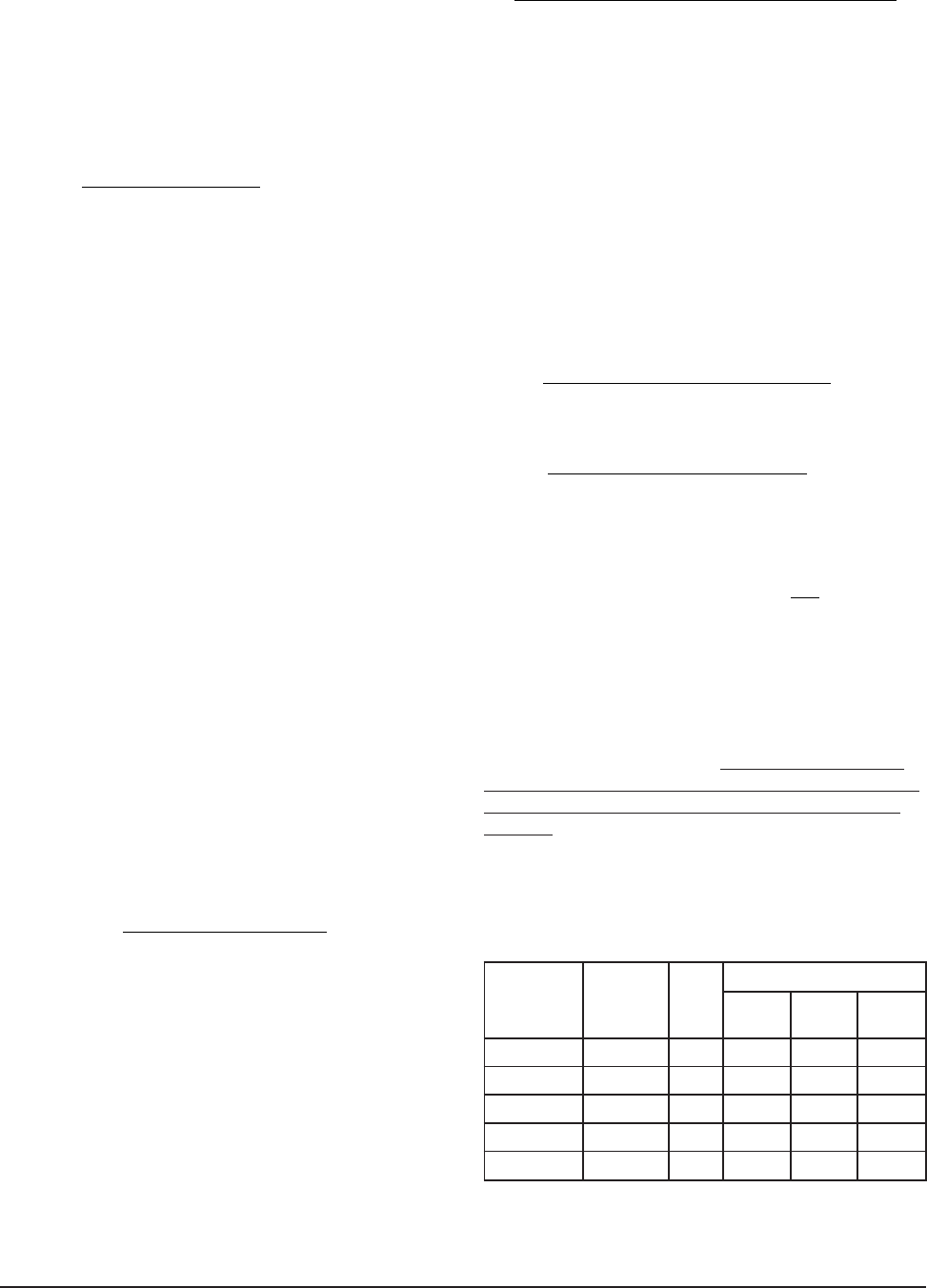
CONTROLLER WIRING
The DC3002 can be used for controlling two (2) air
conditioners with or without economizers. The DC3003
can be used for controlling three (3) air conditioners
with or without economizers. Units with economizers
will connect differently than units without economizers;
therefore, it is important to use the correct connection
diagram. See Table 1 for correct connection diagrams.
noitcennoC margaiD rellortnoC ledoM fo.oN CAVH
dellatsnIrezimonocE
CAVH 1# CAVH 2# CAVH 3#
1erugiF 2003CD2seYseY---
2erugiF 2003CD2
oNoN---
3erugiF 3003CD3ro2seYseYseY
4erugiF 3003CD3ro2seYseYoN
5erugiF 3003CD3ro2oNoNoN
TABLE 1
Manual 2100-484E
Page 11 of 22
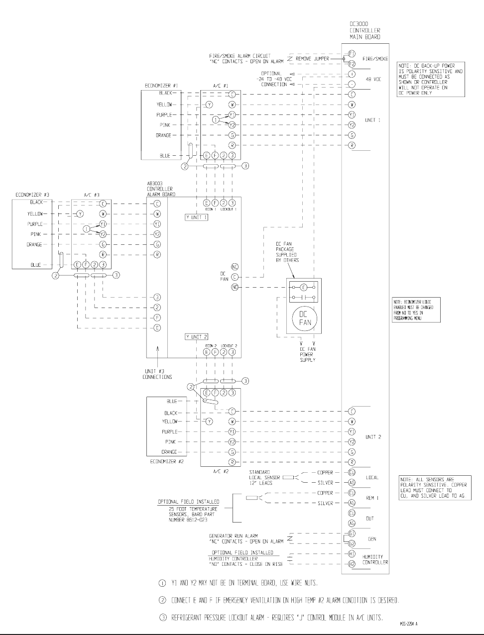
FIGURE 1
DC3002 CONNECTION DIAGRAM
2 UNITS WITH ECONOMIZERS

Manual 2100-484E
Page 12 of 22
FIGURE 2
DC3002 CONNECTION DIAGRAM
2 UNITS NO ECONOMIZERS
Manual 2100-484E
Page 13 of 22
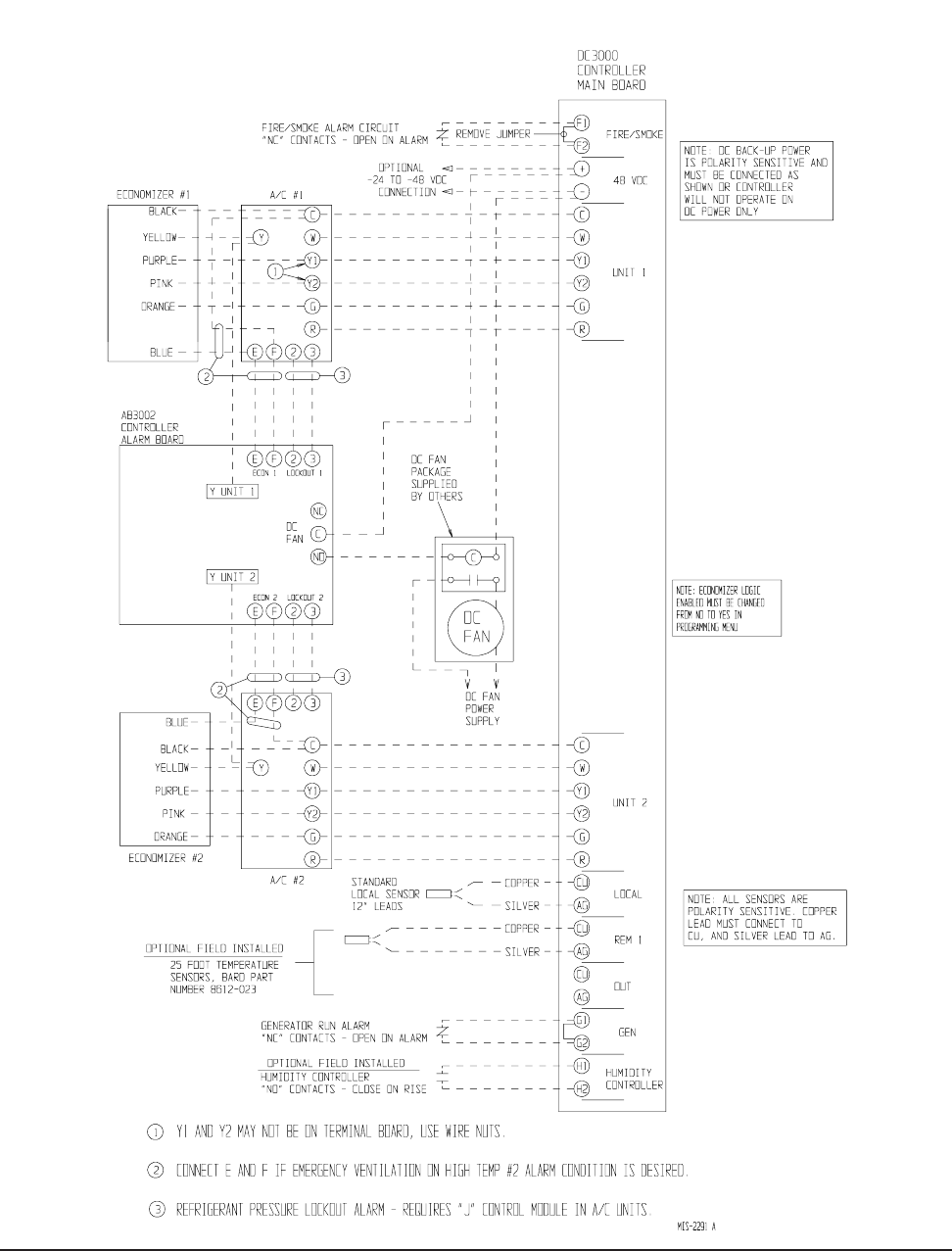
FIGURE 3
DC3003 CONNECTION DIAGRAMS
3 UNITS WITH ECONOMIZERS
Manual 2100-484E
Page 14 of 22
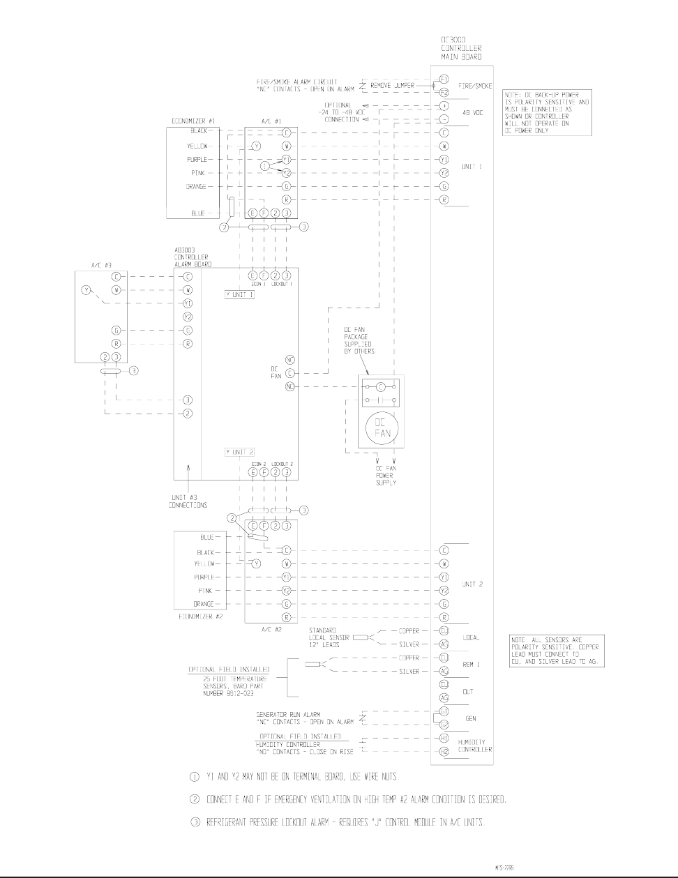
FIGURE 4
DC3003 CONNECTION DIAGRAMS
3 UNITS WITH ECONOMIZERS
(NO ECONOMIZER A/C #3)
Manual 2100-484E
Page 15 of 22
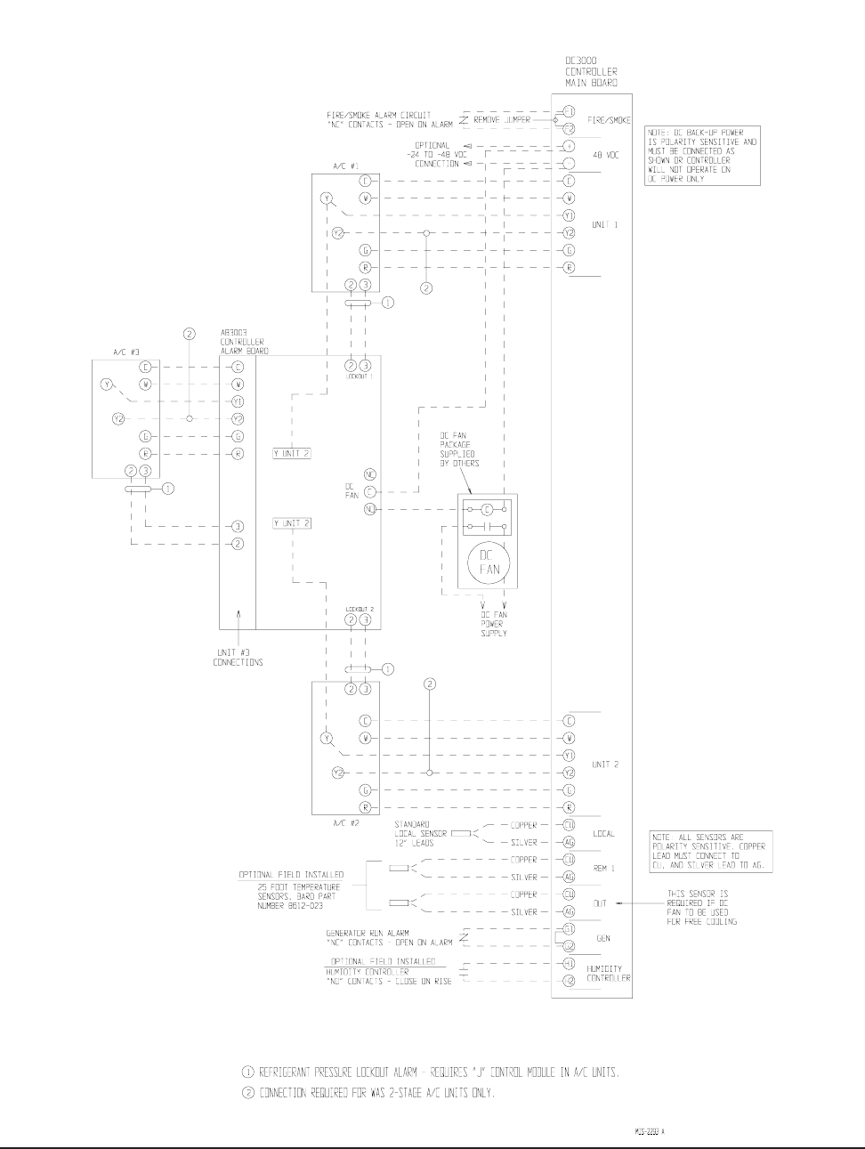
FIGURE 5
DC3003 CONNECTION DIAGRAMS
3 UNITS WITH NO ECONOMIZERS
Manual 2100-484E
Page 16 of 22
ALARM WIRING
Alarm relays can be wired for NO (close on alarm) or
NC (open on alarm) strategy.
Alarm relays can be used individually if there are
enough available building alarm points, or can be
arranged into smaller groups or even a single group so
that all alarm capabilities can be utilized.
When multiple alarms are grouped together and issued
as a single alarm, there will no off-site indication of
which specific problem may have occurred, only that
one of the alarms in the group has been triggered. The
individual alarm problem will be shown on the LED
display on the face of the controller.
Note: All alarm relays are Form C (SPDT) dry contacts
rated 1A @ 24VAC, 120VAC or 150VDC.
The Power Loss and Controller Alarm relays are all
“reverse actuated”, which means they are continuously
energized (the NO contact is closed) and switched to NC
position upon alarm condition. Therefore, it is
important to closely follow the alarm board connection
diagrams that follow.
Any alarm feature that is not desired can simply be
ignored (not connected).
2ND STAGE COOLING ALARM
This alarm output is available for use if desired. It is
important to note that in some installations, due to A/C
system sizing and internal heat load, that the secondary
(lag) air conditioning unit may be called upon to assist
the lead air conditioner some of the time. If this is the
case, or possibly when additional heat load is added,
using the 2nd stage cooling alarm will cause nuisance
alarm conditions.
For installations where it is known that there is 100%
redundancy (one air conditioning unit can handle 100%
of the load 100% of the time) use of the 2nd Stage
Cooling Alarm is a method to issue an alarm signal that
the lead air conditioner is down (or not delivering full
capacity) and that the lag air conditioner is now
operating.
REFRIGERANT PRESSURE ALARMS
Air conditioners with “J” control module are equipped
with an alarm relay that is activated upon high or low
refrigerant pressure lockout conditions. Connecting
terminals 2 and 3 from the air conditioner 24V terminal
block to the matching terminals 2 and 3 on the alarm
board will allow these alarms to function.
EMERGENCY VENTILATION SEQUENCE
USING ECONOMIZERS
For units with economizers, there are two (2) emergency
ventilation sequences designed into the controller. Both
require the connection of terminals E and F from the air
conditioner 24V terminal block to the matching
terminals on the alarm board.
Sequence one requires a refrigerant pressure alarm,
coupled with high temperature alarm condition No. 1
(HAL 1 set point). If both of these conditions occur, the
economizer in the air conditioner that issued the
refrigerant alarm will drive open to ventilate the
building.
Sequence two (HAL 2 set point) is activated by high
temperature alarm No. 2, and will initiate even without a
refrigerant pressure alarm signal. Both economizers will
be activated to provide emergency ventilation. This
strategy help protect against building overheating if air
conditioner(s) are inoperative for non-pressure related
reasons (bad compressor, contactor, run capacitor, etc.).
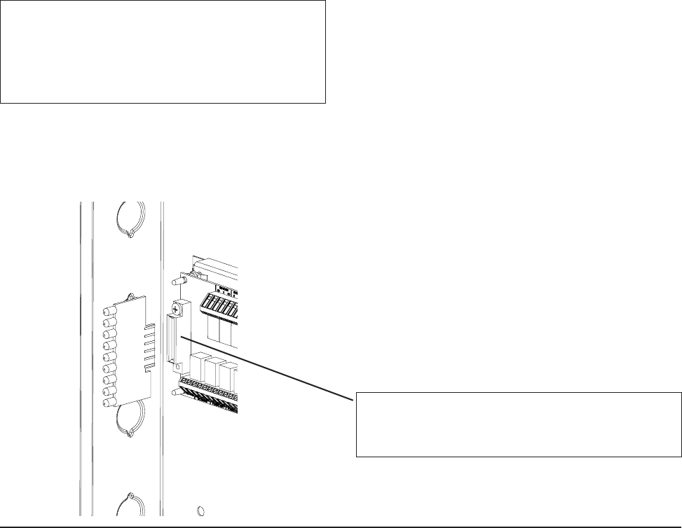
NOTE: The LED display board can be replaced if
needed independently of the alarm board.
Bard part number is 8612-022.
ALARM LED DISPLAY BOARD
MIS-2042
NOTE: The LED display board is polarized and will
only fit in one direction as shown. It must be fully
inserted in order for the controller to function properly.
NOTE: The alarm LED display board is shipped
uninstalled to protect it from possible damage
during installation of the wiring to main
controller board and/or the alarm board. It is
polarity sensitive and is keyed so it can only be
installed in correct position.
Manual 2100-484E
Page 17 of 22
FIGURE 6
ALARM BOARD CONNECTIONS
FOR NORMALLY CLOSED "NC" OPEN-ON-ALARM STRATEGY
Manual 2100-484E
Page 18 of 22
FIGURE 7
ALARM BOARD CONNECTIONS
FOR NORMALLY OPEN "NO" CLOSE-ON-ALARM STRATEGY

Manual 2100-484E
Page 19 of 22
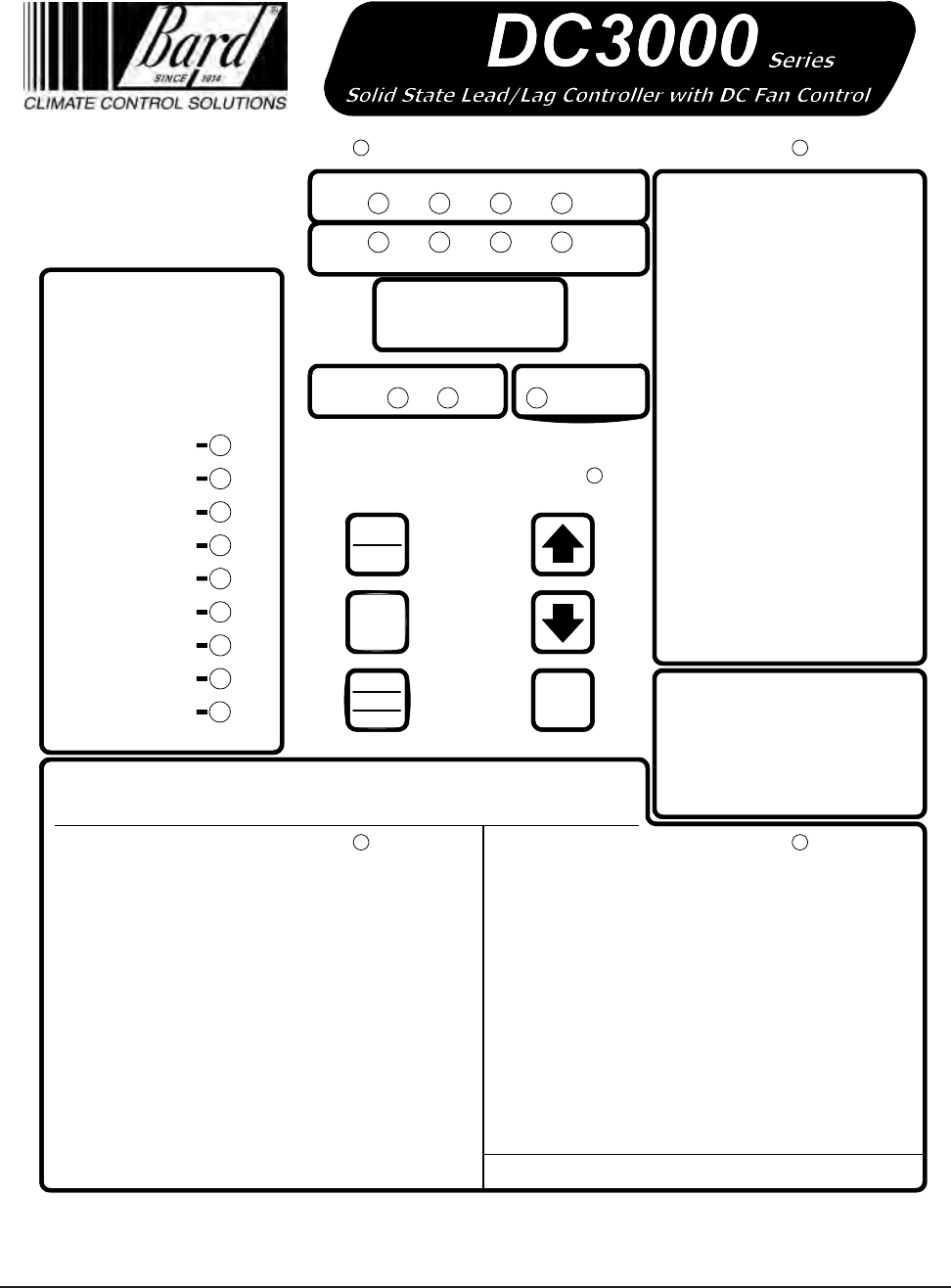
PROGRAMMING INSTRUCTIONS
To swap lead and lag unit positions, press the
ADVANCE button.
To enter the Program mode, press the PROGRAM
button and release it when the message PROG appears
on the display. When in Program mode, the DOWN and
UP arrows are used to scroll through the programming
steps.
NOTE: When using the UP and DOWN arrows, push
for approximately 1 second until the alternating display
goes blank, then release and display will alternate
between the step function and setting.
A FLASHING display means that the function or choice
is “SET”, and the display will alternate between the step
function and setting.
To change the setting of any step, press the CHANGE
button and the display will stop flashing, allowing
change to the setting by using the DOWN or UP arrows.
When desired setting is reached, press the SAVE button,
and proceed as desired. When done with programming
changes, press the PROGRAM button until display stops
flashing and room temperature display is shown. If no
buttons are pushed within thirty (30) seconds, the
controller will automatically revert back to “RUN”
mode.
To reset all controller settings to the factory default
values, press the PROGRAM button for 10 seconds until
display reads dEF.
NOTE: When the controller has the security locking feature enabled, no changes to any selectable features can be
made, and the default reset feature is also locked out. All of the programmable features/settings can be reviewed using
the Program button and Up or Down arrows, but any attempt to change settings using the Change button will result is
display showing “Locd” indicating controller is locked. See section on Security (Locking) Feature.
See next page for Programmable Features, Default Settings and DC3000 front panel label layout.
Manual 2100-484E
Page 20 of 22
7961-665C
Cooling
Heating
1st
Stage 2nd
Stage 3rd
Stage 4th
Stage
1st
Stage 4th
Stage
3rd
Stage
2nd
Stage
Lead
Unit
Unit
#1 Unit
#2 Dehumid.
Operation
Program
Advance Comfort
Digital
Display
Temperature at Remote 1 sensor location*
Lead-lag-change-over time (1 to 30 days
or 0 for disabled, Default is 7)
Cooling setpoint temperature
(65 to 90 deg. F or 18 to 32 deg. C, Default is 75F/24C)
Temperature at local (main) Sensor
Programming Display Menu
Dehumidification Logic Enabled (Yes or No,
Default is No)
Continuous blower operation
(None, Lead, Both, Default is lead)
High temperature alarm level 2 setpoint (70 to 120 deg. F
or 21 to 49 deg. C, Default is 90F/32C)
High temperature alarm level 1 setpoint (70 to 120 deg. F
or 21 to 49 deg. C, Default is 85F/24C)
Low temperature alarm setpoint (28 to 65 deg. F
or -2 to 18 deg. C, Default is 50F/10C) Increase compressor Turn On/Turn Off differential with
excessive compressor cycling (Yes or No, Default is Yes)
3 min. lead unit & 4 min. lag unit off-delay
enabled (Yes or No, Default is No)
System 1 & 2 blowers run if delta T > 5F
between sensors (Yes or No, Default is Yes)
Power Loss Sys. 1
Power Loss Sys. 2
Refrig. Alarm Sys. 1
Refrig. Alarm Sys. 2
Fire/Smoke Alarm
Low Temp. Alarm
High Temp. Alarm 1
High Temp. Alarm 2
Lead/Lag Controller
Failure Alarm
Alarms
Save
Change
On
Off
To swap lead and lag unit positions press
the ADVANCE button.
To enter the Program mode, press the
PROGRAM button and release it when the
message PROG, appears on the display.
When in Program mode the DOWN and
UP arrows are used to scroll through the
programming steps.
A FLASHING display means that the
function or choice is “SET”, and the
display will alternate between the step
function and setting.
To change the setting of any step press
the CHANGE button and the display will
stop flashing, allowing change to the
setting by using the DOWN or UP arrows.
When desired setting is reached press the
SAVE button, and proceed as desired.
When done with programming changes
press the PROGRAM button until display
stops flashing and room temperature
display is shown. If no buttons are pushed
within 30-seconds the controller will
automatically revert back to "RUN" mode.
Programming Instructions
Refer to Installation Instructions for complete details.
* If installed. If sensors are not installed, no display is shown.
See label inside cover for sensor logic.
Locd
Controller is locked and no changes can be made.
Consult building authority.
Press COMFORT button once to reset
to 72°F/22°C Cooling and 68°F/20°C
Heating for 1-hour. Display will flash
72 (or 22) during override period. Press
2nd time to cancel during override if
desired, or will automatically revert after
1-hour.
Comfort Mode
Note: On the DC3003 version the
Lead/Lag Controller alarm light will
"Flash" if Unit #3 has Power Loss
or Refrig. Alarm. Open cover to
observe Fault light that is on the
alarm board located inside.
SP
Temperature at Outdoor sensor location*
DC Fan Operation (Edcf "emergency vent only",
Free "cooling", Both. Default is Both)
r I
Loc
Out
LLOC
cFAn
LoAL
HALI
HAL2
dFAn
Outdoor temperature setpoint for DC Fan
operation. Requires Outdoor Sensor (50-55-60F, Default is 55)
dFon
Deadband between cooling and heating setpoint
(2 to 20 deg. F or 1 to 11 deg. C, Default is 10F/5C)
db
dE9
Degrees shown in F or C (F or C, Default is F)
HuLE
CbdS
OFdE
Minimum 3 minute compressor run time
enabled (Yes or No, Default is No)
crun
CHYS
DC fan Purge duration in minutes
(No,1,2,3,4,5,6,7,8,9,10 Default is No)
Interval between DC Fan Purge cycles in Hours
(1,2,3,4,5,6,7,8,9,10 up to 24 Default is 1,
Pint display is suppressed if Purg is No)
Purg
Pint
Manual 2100-484E
Page 21 of 22
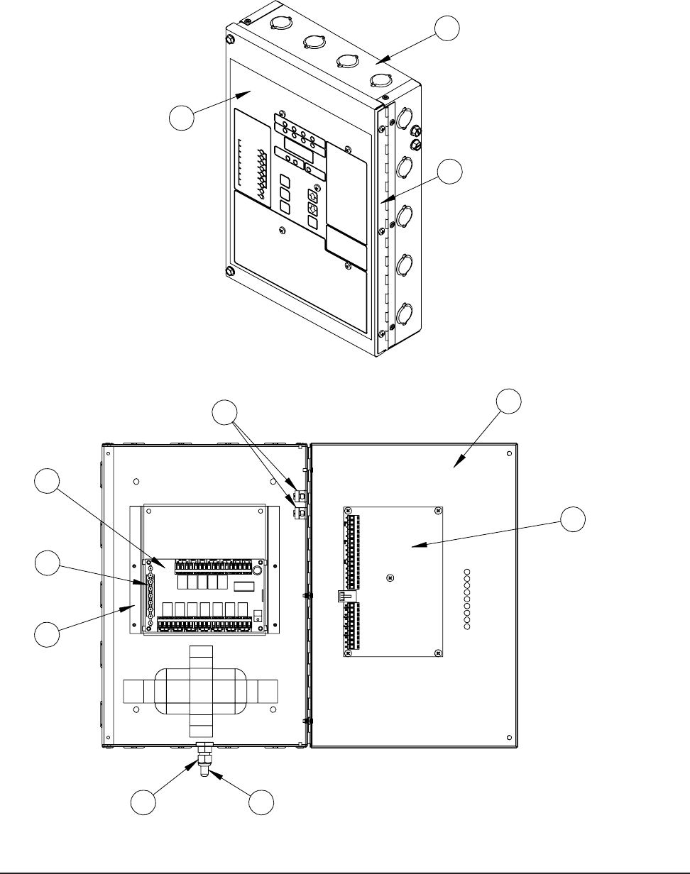
FIGURE 8
PARTS LIST DESCRIPTION DIAGRAM
5
7
3
4
6
9
2
11
SEXP-445 B
8
1
10

Manual 2100-484E
Page 22 of 22
Parts List
.oN.gwD.oNtraPnoitpircseD2003CD3003CD
14-343-721xoBlortnoCXX
2730-2168draoBrellortnoCXX
3520-21682003BAdraoBmralAX
3620-21683003BAdraoBmralAX
4220-2168yalpsiDmralAX
54-043-311tekcarBtroppuSX
X
64-583-251rooDxoBlortnoCXX
7990-1168gnittiFFTLXX
8200-0045egniHX
X
9320-2168rosneSXX
01366-1697dapyeK/lebaLXX
TABLE 2
