Baron Services KHDD-1000C WEATHER RADAR SYSTEM User Manual Sigmet RVP8 Users Guide
Baron Services Inc WEATHER RADAR SYSTEM Sigmet RVP8 Users Guide
UserManual.wiki
>
Baron Services
>
KHDD-1000C User Manual
>
Sigmet RVP8 Users Guide
Contents
1.
Sigmet RVP8 Users Guide
2.
Page 143 of the Sigmet RVP8 Manual
Sigmet RVP8 Users Guide
Navigation menu
Upload a User Manual
Namespaces
Wiki Guide
HTML
PDF
Info
Views
User Manual
Discussion / Help
Navigation
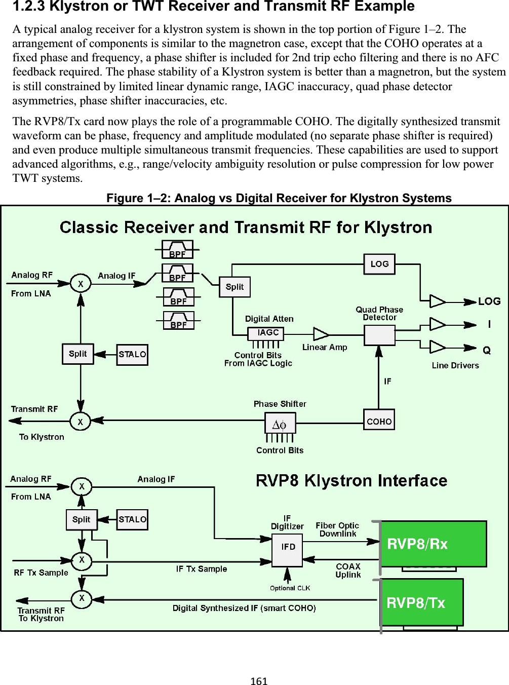
![168Time (azimuth) Averaging The autocorrelations are based on input “I” and “Q” values over a selectable number of pulses between 8, 9, 10, ...,256. Any integer number of pulses in this interval may be used including DFT/FFT and random phase modes. Selectable angle synchronization using the input AZ and EL tag lines assures that all possible pulses are used during averaging for each, say, 1 degree interval. This minimizes the number of “wasted” pulses for maximum sensitivity. Azimuth angle synchronization also assures the accurate vertical alignment of radial data from different elevation angles in a volume scan (see below). TAG Angle Samples of Azimuth and Elevation During data acquisition and processing it is usually necessary to associate each output ray with an antenna position. To make this task simpler the RVP8 samples 32 digital input “TAG” lines, once at the beginning and once at the end of each data acquisition period. These samples are output in a four-word header of each processed ray. When connected to antenna azimuth and elevation, the TAG samples provide starting and ending angles for the ray, from which the midpoint could easily be deduced. Since the bits are merely passed on to the user, any angle coding scheme may be used. The processor also supports an angle synchronization mode, in which data rays are automatically aligned with a user-defined table of positions. For that application, angles may be input either in binary or BCD. Range Averaging and Clutter Microsuppression To improve the accuracy of the reflectivity measurements, the RVP8 can perform range averaging. When this is done, autocorrelations from consecutive range bins are averaged, and the result is treated as if it were a single bin. This type of averaging is useful to lower the number of range bins that the host computer must process. Range averaging of the autocorrelations may be performed over 2, 3, 4, ..., 16 bins. Prior to range averaging, any bins that exceed the selectable clutter-to-signal threshold are discarded. This prevents isolated strong clutter targets from corrupting the range average, which improves the sub-clutter visibility. Moment Extraction The autocorrelations serve as the basis for the Doppler moment calculations, Mean velocity – from Arg [ R1 ] Spectrum width – from |R1| and |R2| assuming Gaussian spectrum dBZ – from R0 with correction for ground clutter, system noise and gaseous attenuation. Uses calibration information supplied by host computer. dBT – identical to dBZ except without ground clutter. These are the standard parameters that are output to the host computer on the high-speed Ethernet interface.](https://usermanual.wiki/Baron-Services/KHDD-1000C.Sigmet-RVP8-Users-Guide/User-Guide-947898-Page-28.png)