Beautiful Enterprise K401 Kinoma Create User Manual Print
Beautiful Enterprise Co., Ltd. Kinoma Create Print
User Manual
User Manual
Model K4-01
Table of Contents
1. Important Information
2. Kinoma Create hardware
4. First Run
7. Powering on/o
8. Charging internal battery
9. Network Connection: Wi-Fi
10. Settings
14. On-board applications
17. Setting up a bootable SD card
18. Connecting to PC
19. Using Hardware Pins (Front Pins)
20. Using Hardware Pins (Rear Pins)
21. Kinoma Create Stand
22. FCC Statement
Important Information about Kinoma Create
The most important thing to know is that Kinoma Create is primarily a
3.3-volt system. If you’re new to 3.3v systems or to hardware in general, this
means that (unlike with an Arduino or some other boards), you can only send
up to 3.3 volts into any input pin on the device without doing damage to
the pin.
Download Kinoma Studio. You can try out your own applications in our
desktop simulator, build apps for iOS and Android, or run any of our samples
(included with Kinoma Studio) on your Kinoma Create.
Our team is ready to support you as you work with your Kinoma Create. The
best way to get answers to your questions is to post on the Kinoma Forum
(http://forum.kinoma.com/). We will post there, and email a second time,
once the hardware documentation is available.
We want you all to successfully bring your product concepts to life, and we’ll
be here to help you along the way. Enjoy your Kinoma Create!
1
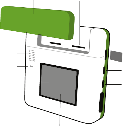
Cable port for routing
cables out from rear
pins
16 pins configurable for:
• 5V or 3.3V power
• Ground
• Digital input/output
• Analog input
• I2C
• PWM
• Serial
Removable sensor cover
Speaker microSD slot
USB 2.0
including USB On-The-Go
Microphone
Mini USB serial console port
Color screen
Capacitive touch screen
Kinoma Create Front
2
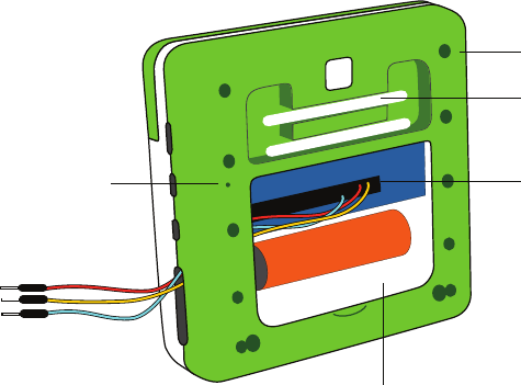
Removable access panel
50 pins for:
• 3.3V power
• Ground
• Digital input/output
• Analog input
• I2C
• PWM
• Serial
Stand Dowels
Stand Holes
Reset
Kinoma Create Back
3
Kinoma Create First Run
4
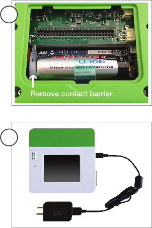
1
2Begin charging device with supplied
charger. (Note: Kinoma Create uses
special charging circuitry and requires a
sensing charger to correctly charge the
battery. Only use the provided charger,
since other chargers may not charge the
battery).
Remove back cover and pull out battery
contact shield.
3
4
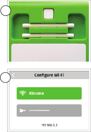
Press the power button on the back of
Kinoma Create. Kinoma Create typically
takes 35 seconds to boot up.
Use the Wi-Fi app to add your Kinoma
Create to your network..
Kinoma Create First Run
5
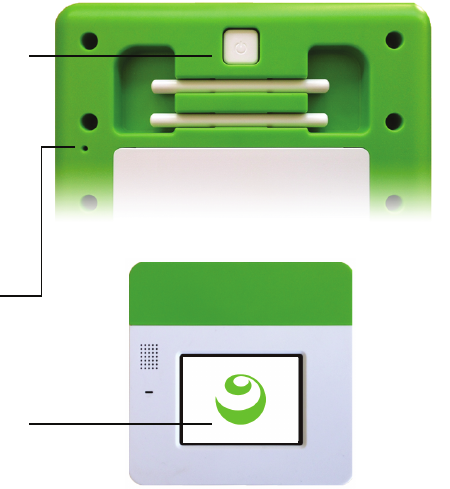
5Set the time zone for your device.
Kinoma Create First Run
6
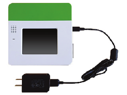
Power On/O
Press to start
If powered up, long press shuts
down
If powered up, and a short
press, device enters hibernate
mode.
If powered up, and in hibernate
mode, a short press wakes up
Reset device button. Use paper
clip or similar to reach reset
button and perform a hard
reset.
This screen shows during boot
up. Kinoma Create typically
takes 35 seconds to start. 7
Charging internal battery
Kinoma Create uses special charging
circuitry and requires a sensing charger
to correctly charge the battery. Only use
the provided charger, since other char-
gers may not charge the battery
8
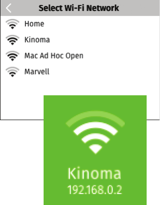
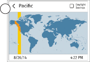
Network Connection: Wi-Fi
Clicking the “Select network” button
displays a list of available networks.
Select a network and enter password
if necessary. Kinoma Create remem-
bers the last configured Wi-Fi network.
Aer connecting to a network the
device IP address is shown on the
Wi-Fi tile.
9
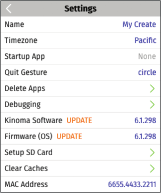
Settings
The Settings app on Kinoma Create
allows for setting attributes, updating
device and viewing device information.
If updates are available an UPDATE
notification will appear. Tap to update.
10
Settings
11
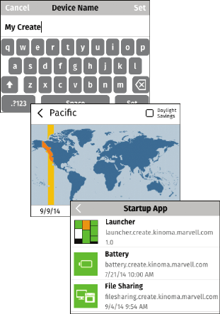
Name: Set Device name if needed. This is
the name that this Kinoma Create will
use for network connections, including
debugging in the Kinoma Studio IDE.
Time zone: It is important to set the
local timezone for apps that use time and
date based APIs. The optional day light
savings check box needs to be manually
update to match local conditions.
Startup App: For testing Kinoma Create
can be set to launch into a specific app.
The default is the Kinoma Create
Launcher app.
12
Settings
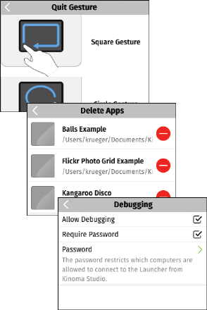
Quit Gesture: Allows selection of quit
gesture
Delete Apps: Allows removal of apps
that have been installed on Kinoma
Create. Note: Built-in apps, such as Wi-Fi
and Settings cannot be deleted.
Debugging: Kinoma Create can be set to
allow debugging over Wi-Fi and require a
password to debug.
Kinoma Soware: Shows the current
version number and Updates if available.
13
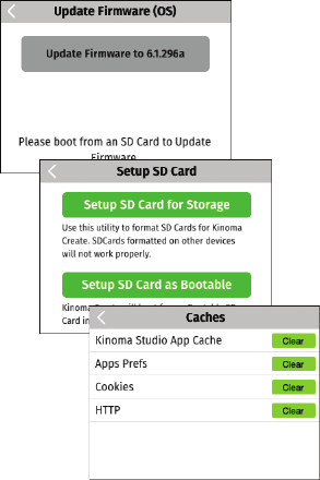
Settings
Firmware (OS): Shows the current
firmware version number and Updates if
available.
Setup SD card: Format and partition an
SD to become a bootable file system
Clear Caches: Allows clearing of Kinoma
Studio App, Cookie and HTTP caches
MAC Address: Shows the MAC address
of this Kinoma Create. The MAC address
is the unique id of the device.
On Board Apps
14
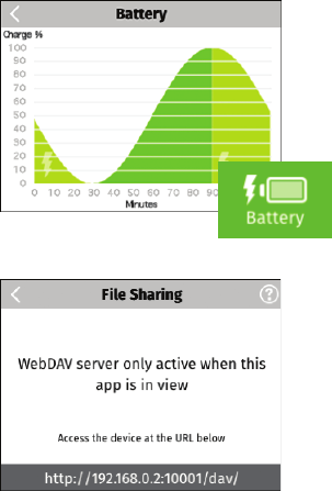
Battery: Shows current charge status on
the tile and chargingand usage history in
the app view.
File Sharing App: Allows mouning your
Kinoma Create on your PC (Windows and
Mac). File Sharing implements the
WebDAV protocol
15
On Board Apps
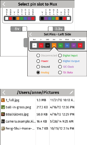
Front Pins: The 16 front facing pins can
be targeted by the Front Pins app to
support Digital, Analog In, and I2C
connections. Power can be supplied at
3.3 or 5 volts. Input pins will handle up to
3.3v.
Files: Files app provides simple view and
management functionality for files on
Kinoma Create. It can display PNG and
JPEG images, MPEG-4 files, and the first
8KB of text based files. Individual files
can be deleted.
16
On Board Apps
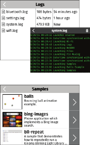
Logs: Presents information about the
operation of Kinoma Create. Kinoma
Create logs PinMux settings, Settings,
system events and Wi-Fi configurations.
Developers can add new logs or data to
existing logs.
Samples: Shows current contents from
the Kinoma GitHub Samples repository.
Select samples to download and view on
the device. Select View Source to view
the JavaScript source and other project
assets.
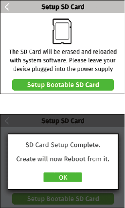
Setting up a bootable SD card
17
Install an SD card and you can set it up as
a bootable volume. As part of the setup
process, the latest Kinoma Create setup
image will downloaded.
Kinoma Create will start from a bootable
SD card if present.
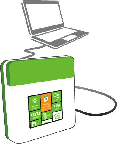
18
You can connect your Kinoma Create to
your PC via either Micro USB or Mini USB
to power it.
If you connect via the Mini USB Port, you
can access the serial console.
Connecting to a PC
19
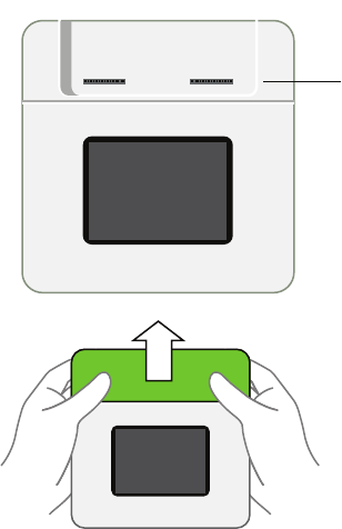
Using Hardware Pins (Front)
Front Pins: The 16 front facing pins can
be targeted by the Front Pins app to
support Digital, Analog In, and I2C
connections. Power can be supplied at
3.3 or 5 volts. Input pins will handle up to
3.3v. The front pins are designed to
conveniently fit readily-available sensors.
Open Sensor Cover
While holding onto the sides of Kinoma
Create, press up on the sensor cover with
your thumbs.
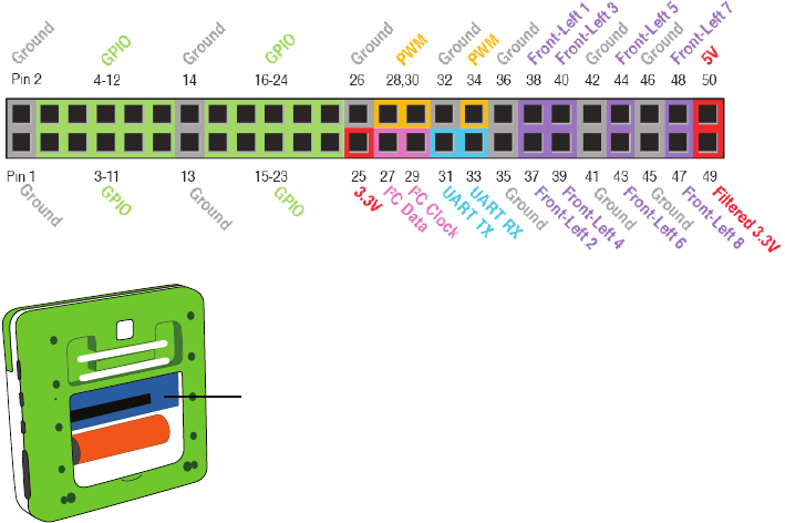
20
Using Hardware Pins (Rear)
Rear Pins: The 50 pins accessible behind the rear
access panel have dedicated functionality to
support Digital, Analog Input, PWM, I2C, and Serial
connections. Power can be supplied at 3.3 or 5
volts. Input pins will handle up to 3.3v.
For more information on coding with the
hardware pins visit kinoma.com/create
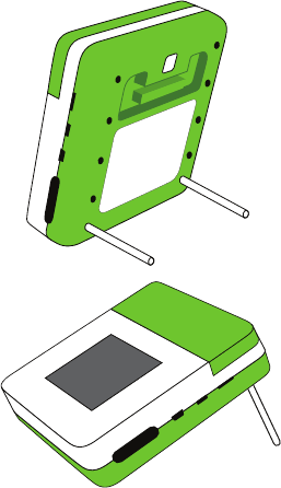
Kinoma Create Stand
Kinoma create includes an adjustable
stand. Use the dowels in the rear in the
stand holes to set the stand to the angle
desired.
21
FCC Statement
22
This equipment has been tested and found to comply with the limits for a Class B digital device,
pursuant to part 15 of the FCC Rules. These limits are designed to provide reasonable protection
against harmful interference in a residential installation. This equipment generates, uses and
can radiate radio frequency energy and, if not installed and used in accordance with the
instructions, may cause harmful interference to radio communications. However, there is no
guarantee that interference will not occur in a particular installation. If this equipment does
cause harmful interference to radio or television reception, which can be determined by turning
the equipment o and on, the user is encouraged to try to correct the interference by one or
more of the following measures:
— Reorient or relocate the receiving antenna.
— Increase the separation between the equipment and receiver.
— Connect the equipment into an outlet on a circuit dierent from that to which the receiver is
connected.
— Consult the dealer or an experienced radio/TV technician for help.
FCC Radiation Exposure Statement
23
This equipment complies with FCC RF radiation exposure limits set forth for an uncontrolled
environment. This transmitter must not be co-located or operating in conjunction with any
other antenna or transmitter. This equipment should be installed and operated with a
minimum distance of 20 centimeters between the radiator and your body.
This device complies with Part 15 of the FCC Rules. Operation is subject to the following two
conditions: (1) this device may not cause harmful interference, and (2) this device must accept
any interference received, including interference that may cause undesired operation.
Caution!
Any changes or modifications not expressly approved by the party responsible for compliance
could void the user's authority to operate the equipment.
Canada Statement
24
This device complies with Industry Canada licence-exempt RSS standard(s). Operation is
subject to the following two conditions: (1) this device may not cause interference, and (2) this
device must accept any interference, including interference that may cause undesired
operation of the device.
Le présent appareil est conforme aux CNR d'Industrie Canada applicables aux appareils radio
exempts de licence. L'exploitation est autorisée aux deux conditions suivantes : (1) l'appareil ne
doit pas produire de brouillage, et (2) l'utilisateur de l'appareil doit accepter tout brouillage
radioélectrique subi, même si le brouillage est susceptible d'en compromettre le
fonctionnement.
The device meets the exemption from the routine evaluation limits in section 2.5 of RSS 102 and
compliance with RSS-102 RF exposure, users can obtain Canadian information on RF exposure
and compliance.
Le dispositif rencontre l'exemption des limites courantes d'évaluation dans la section 2.5 de
RSS 102 et la conformité à l'exposition de RSS-102 rf, utilisateurs peut obtenir l'information
canadienne sur l'exposition et la conformité de rf.
Canada Statement (continued)
25
This transmitter must not be co-located or operating in conjunction with any other antenna or
transmitter. This equipment should be installed and operated with a minimum distance of 20
centimeters between the radiator and your body.
Cet émetteur ne doit pas être Co-placé ou ne fonctionnant en même temps qu'aucune autre
antenne ou émetteur. Cet équipement devrait être installé et actionné avec une distance
minimum de 20 centimètres entre le radiateur et votre corps.

Copyright © 2002 – 2014 Kinoma, Inc.
Marvell, Kinoma, and the M logo are registered trademarks of Marvell and/or its ailiates. Other names and brands may be claimed as
the property of others.
Kinoma Create incorporates open source soware; details are at http://kinoma.com/create/opensource/.
Hardware design files provided under Creative Commons Attribution 4.0 International License.
Sample code provided under Apache License, Version 2.0.
Kinoma Create does not include an SD memory card.