Becker Avionics AR6203 VHF-Transceiver User Manual VHF Transceiver Family 620X
Becker Flugfunkwerk GmbH VHF-Transceiver VHF Transceiver Family 620X
user manual

Becker Avionics GmbH • Baden-Airpark B108
77836 Rheinmünster • Germany •
+49 (0) 7229 / 305-0 • Fax +49 (0) 7229 / 305-217
http://www.becker-avionics.com • E-mail: info@becker-avionics.com
VHF Transceiver
AR6201, AR6203, RT6201, RCU6201
Software Versions:
from Software Version
SCI1050S305 Version 4.06
SCI1051S305 Version 2.06
Operating Instructions
Article-No.: 0638.420-071
Issue 03 July 2015

Operating Instructions
2 VHF Transceiver Family 620X 0638.420-071 Issue 03 July 2015
Table of Contents
Table of Contents ................................................................................................ 2
List of Abbreviations ........................................................................................... 3
Units ..................................................................................................................... 4
1. Introduction ................................................................................................. 5
1.1. General Safety Definitions ............................................................................ 5
1.2. Warranty Conditions ..................................................................................... 6
1.3. Conditions of Utilization ................................................................................ 6
1.3.1. Purpose of Equipment ................................................................. 6
1.3.2. Additional Conditions of Utilization .............................................. 6
1.4. Non Warranty Clause ................................................................................... 6
2. Operating Instructions ............................................................................... 7
2.1. Device Description ........................................................................................ 7
2.1.1. Device Assignment...................................................................... 7
2.1.2. Type Specification Label ............................................................. 8
2.1.3. Safety-Conscious Utilization ........................................................ 9
2.2. Controls and Indicators ............................................................................... 10
2.3. Start-Up ...................................................................................................... 12
2.4. Receive and Transmit Mode ....................................................................... 12
2.4.1. Receive Mode ........................................................................... 12
2.4.2. Transmit Mode .......................................................................... 12
2.5. Frequency Selection Modes ....................................................................... 13
2.5.1. Standard Mode .......................................................................... 14
2.5.2. Direct Tune Mode ...................................................................... 16
2.5.3. Channel Mode ........................................................................... 17
2.5.4. Frequency Storage Functions ................................................... 18
2.5.5. Automatic Storage Function ...................................................... 20
2.5.6. Scan Mode ................................................................................ 20
2.6. SQUELCH .................................................................................................. 21
2.7. RX Field Strength Indication ....................................................................... 22
2.8. Channel Spacing Mode .............................................................................. 22
2.9. Auxiliary Audio Input ................................................................................... 23
2.10. Intercom Operation ..................................................................................... 24
2.11. VOX & Speaker Operation .......................................................................... 26
2.12. Menus ......................................................................................................... 26
2.12.1. Intercom Menu .......................................................................... 26
2.12.2. Pilots Menu ............................................................................... 28
2.13. Warning and Failure Indications ................................................................. 30
3. Index .......................................................................................................... 32

Operating Instructions
0638.420-071 Issue 03 July 2015 VHF Transceiver Family 620X 3
List of Abbreviations
List of Abbreviations
FAA
Federal Aviation Administration
AC
Alternating Current
AF
Audio Frequency
AR
Airborne Radio
ATT
Attenuation
AUX
Auxiliary
AWG
American Wire Gauge
BNC
Bayonet Neill Concelman
CBIT
Continuous Built-In Test
CFG
Configuration
CH
Channel
CM
Chassis Module
COM
Communication
DC
Direct Current
EASA
European Aviation Safety Agency
EMI
Electro Magnetic Interference
ETSO
European Transmission System Operators
EUROCAE
European Organisation for Civil Aviation Equipment
GND
Ground (Aircraft Ground)
GPS
Global Positioning System
HMI
Human Machinery Interface
HIRF
High Intensity Radiated Fields
IC
Intercom
I&O
Installation & Operation
LCD
Liquid Crystal Display
MFD
Multi-Function Display
M&R
Maintenance & Repair
N/A
Not Applicable
NAV
Navigation
PBIT
Power-On Built In Test
PTT
Push To Talk
PWR
Power
RCU
Remote Control Unit
RSSI
Received Signal Strength Indication

Operating Instructions
4 VHF Transceiver Family 620X 0638.420-071 Issue 03 July 2015
List of Abbreviations
RT
Remote Transceiver
RX
Receive
SQL
Squelch
SPKR
Speaker (Loudspeaker)
SRC
Source
SW
Software
TSO
Technical Standard Order
TX
Transmit
VOX
Voice Operated IC Threshold
VHF
Very High Frequency
VDC
Voltage Direct Current
VSWR
Voltage Standing Wave Ratio
VU
Volume Unit
Units
Units
V
Volt
mV
Millivolt
A
Ampere
mA
Milliampere
W
Watt
mW
Milliwatt
kHz
Kilohertz
MHz
Megahertz
s
Second
dBm
Power ratio in Decibel
dB
Decibel
Ohm (Ω)
Resistor
kg
Kilogram
°C
Degree Celsius
mm
Millimetre
cm
Centimetre

Operating Instructions
General Safety Definitions
0638.420-071 Issue 03 July 2015 VHF Transceiver Family 620X 5
1. Introduction
Before use of the VHF Transceiver it is recommended to study this
instruction manual carefully because it contains safety as well as operating
instructions.
Include this manual to the documentation carried on board the aircraft.
For further descriptions we are using following terms for VHF transceivers,
VHF remote transceiver and remote control unit, instead writing their
complete model number.
620X in general for the device family
AR620X for: AR6201, AR6203 (Single Block Transceiver)
RT for: RT6201 (Remote Transceiver)
RCU for: RCU6201 (Remote Control Unit)
1.1. General Safety Definitions
Indicates a hazardous situation which, if not avoided,
will result in death or serious injury.
Indicates a hazardous situation which, if not avoided,
could result in death or serious injury.
Indicates a hazardous situation which, if not avoided,
could result in minor or moderate injury.
Is used to address practices not related to physical
injury.
Safety instructions (or equivalent) signs indicate
specific safety-related instructions or procedures.

Operating Instructions
Non Warranty Clause
6 VHF Transceiver Family 620X 0638.420-071 Issue 03 July 2015
1.2. Warranty Conditions
User Conversions and Changes are Not Permitted
Any change made by the user excludes any liability on our part (excluding
updates for the navigation data base).
• The device must not be opened.
• Do not make any modifications to the device, except for those
described in the manual.
• Make connections to the inputs, outputs and interfaces only in
the manner described in the manual.
• Fix the devices according to the mounting instructions.
We cannot provide any guarantee for other mounting methods.
1.3. Conditions of Utilization
General introductory notes
With this device you bought a product which was manufactured and tested
before delivery with the utmost care. Please take your time to read the
following notes which you ought to follow closely during installation and
operation. Unless, all claims under the warranty will become void and a
reduced service life or even damages must be expected.
The user is responsible for protective covers and/or
additional safety measures in order to prevent
damages to persons and electric accidents.
1.3.1. Purpose of Equipment
The VHF transceiver enables voice communication in the very high
frequency band between 118.000 to 136.9916 MHz (radio communication
part of air-band) with a selectable channel spacing of 25 or 8.33 kHz.
1.3.2. Additional Conditions of Utilization
Please refer to "Safety-Conscious Utilization", page 9.
1.4. Non Warranty Clause
We checked the contents of this publication for compliance with the
associated hard and software. We can, however, not exclude discrepancies
and do therefore not accept any liability for the exact compliance. The
information in this publication is regularly checked, necessary corrections
will be part of the subsequent publications.

Operating Instructions
Device Description
0638.420-071 Issue 03 July 2015 VHF Transceiver Family 620X 7
2. Operating Instructions
The chapter "Operating Instructions" contains general information and
instructions to ensure safe operation of the VHF transceivers.
2.1. Device Description
In this section the figures for illustrating display
content mainly show transceivers working in
8.33/25 kHz mixed mode. Dedicated pictures for
25 kHz mode are not explicitly shown (they differ
only in number of digits for frequency).
The HMI actions described in this section can be
performed on primary controller or on optional
secondary controller RCU6201.
The following graphics of the display content show
the 8.33 kHz channel spacing for all possible
operation modes.
2.1.1. Device Assignment
This manual is valid for the following devices:
• AR6201-(XX2)
• AR6203-(XX2)
• RT6201-(XX0) with RCU6201-(X12)
from Software Version
SCI1050S305 Version 4.06
SCI1051S305 Version 2.06
Operating Instructions
Device Description
8 VHF Transceiver Family 620X 0638.420-071 Issue 03 July 2015
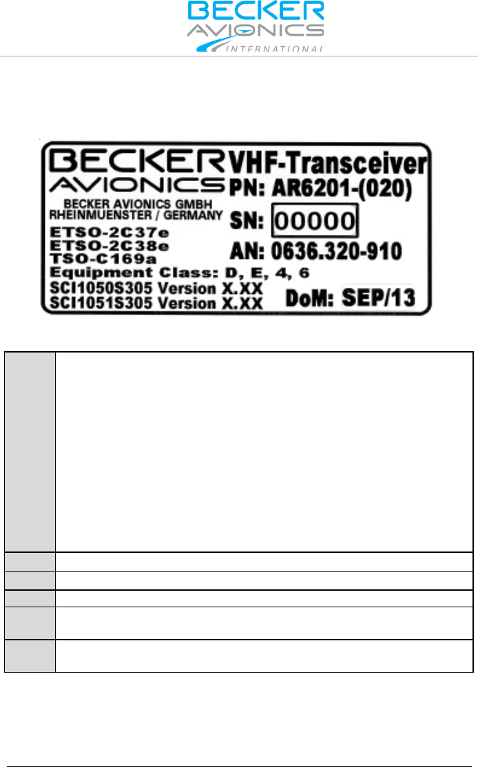
2.1.2. Type Plate
The device type is defined by the type plate (on the housing):
Figure 2-1: Type plate (example)
Explanation:
PN:
Type designation:
AR6201 = Single Block VHF Transceiver 58 mm (2¼ inch)
AR6203 = Single Block VHF Transceiver 160 mm (6.3 inch)
RT6201 = Remote VHF Transceiver
RCU6201 = Remote Control Unit 58 mm (2¼ inch)
Options:
0XX: 8.33/25 kHz channel spacing capability
1XX: 25 kHz channel spacing capability only
X1X: 10 W at 28 V
X2X: 6 W at 12 V
XX2: white illumination colour on black panel
SN:
Unique number of the particular device
AN:
Article number
DoM:
Date of Manufacturing
Software:
Corresponding to the displayed version
Compliance and Certifications
Corresponding to the displayed text and logos

Operating Instructions
Device Description
0638.420-071 Issue 03 July 2015 VHF Transceiver Family 620X 9
2.1.3. Safety-Conscious Utilization
Switch OFF the device before starting or shutting
down engines.
A voice communication test shall be performed
before starting the engine.
It should be noted that, if the communication test is
carried out close to a ground station, the results may
be positive even if the antenna cable is broken or
short-circuited. In such a case, at a distance of 5 to
10 km and above, communication might not be
possible.
• Speak always loud, clear and not too fast for optimal voice
communication.
• Keep the microphone always close to the lips otherwise a
special suppressing circuit in the VHF COM will not be capable
to suppress normal cabin noise.
• Use only microphones or headsets which are suitable for use
in an aircraft.
o In aircraft made of wood, synthetic materials or in gliders or
helicopters, incoming radiation can affect the integrated
amplifier of the microphone (feedback), noticeable in the
ground station by whistling and/or heavy distortion.
If the power supply voltage drops below the "Low Battery Threshold"
(default value is 10.5 V), the "LOW BATTERY" message will appear each
3 seconds in the lower part of the display.
If the power supply voltage drops below 10 V the
system enters power saving mode:
• Speaker output of the transceiver is automatically
switched "OFF"
• Speaker sign will no longer be presented on LCD
display
• The pilot must use headphones to continue
listening.
Operating Instructions
Controls and Indicators
10 VHF Transceiver Family 620X 0638.420-071 Issue 03 July 2015
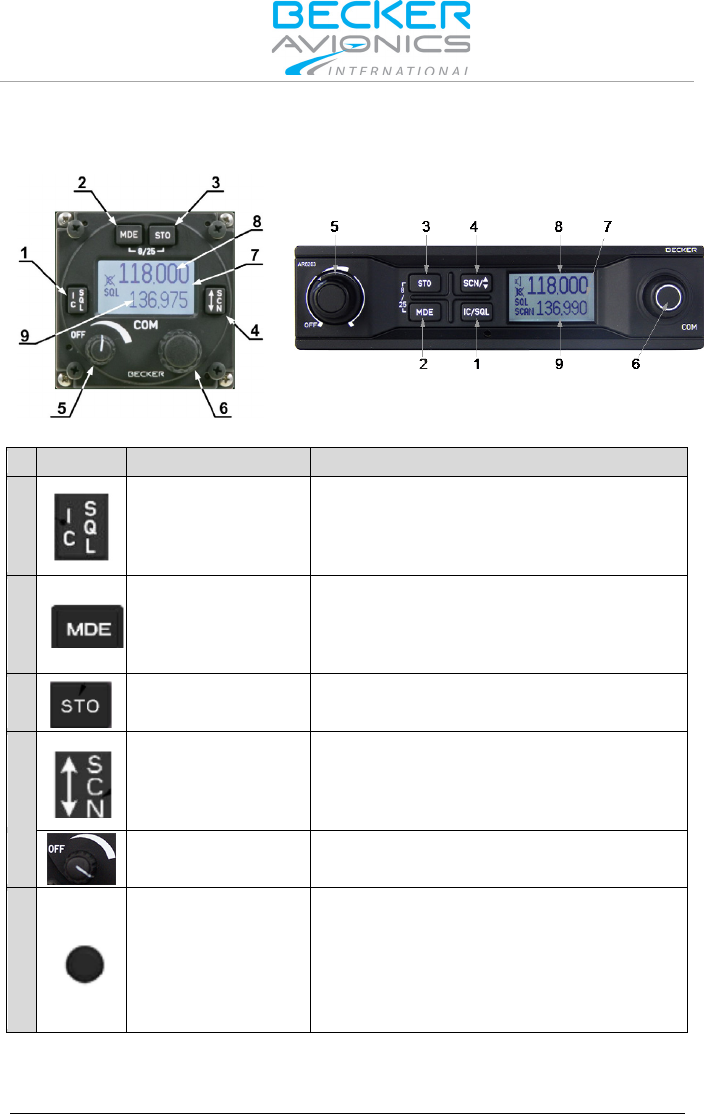
2.2. Controls and Indicators
AR620X and RCU6201
AR6203
Figure 2-2: Controls and indicators
Symbol
Description
Main Function
1
IC/SQL
(Intercom/Squelch)
"Short press" during normal operation
toggles the RX -SQL ON/OFF.
"Long press" during normal operation
activates Intercom Menu.
2
MDE
(Mode)
"Short press" during normal operation
changes the frequency selection mode.
"Long press" during normal operation
activates the pilots menu.
3
STO
(Store)
"Short press" during normal operation
activates storage procedure.
4
↨/SCN
(Exchange/SCAN)
"Short press" during standard mode, or
scan mode toggles between preset and
active frequency.
"Long press" activates scan mode.
5
Power ON/OFF,
Volume Knob
Switches the transceiver ON/OFF and
adjusts volume level of received signal.
6
Rotary encoder
Turning "ROTARY ENCODER" changes
the settings of several parameters
(frequency, IC-volume, VOX, …).
Pushing the "ROTARY ENCODER"
toggles between the digits and acts as
an enter key.
Operating Instructions
Controls and Indicators
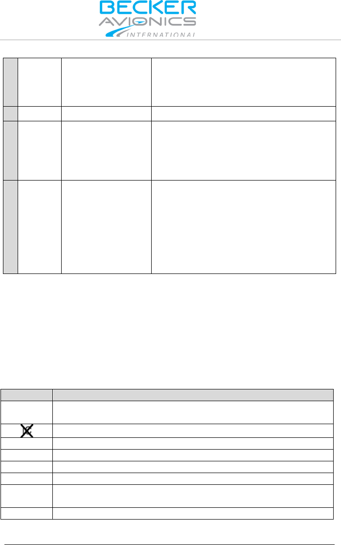
0638.420-071 Issue 03 July 2015 VHF Transceiver Family 620X 11
-8/25-
Change of Channel
Spacing
Keeping the MOD and STO button
pressed simultaneously longer than
2 seconds changes 8.33 to 25 kHz
channel spacing and vice versa.
7
Display
LCD: Liquid Crystal Display
8
Active frequency
Only on the active frequency,
transmitting is possible and receiving
has priority, even in scan mode.
Frequency tuning is not possible in
standard mode.
9
Preset frequency
Frequency tuning is possible in standard
mode. In scan mode both frequencies,
active and preset are in listening watch.
If no receive signal is detected on the
active frequency, receiving signals on
the preset frequency will be audible, but
will be muted as soon as a signal on the
active frequency is detected.
The device detects a:
"Long press": when pressing and holding down a key for at least
2 seconds.
"Short press": any pressing below 2 seconds.
If any action by the user is invalid, the whole display inverting for a short
time.
Symbols shown on the Display
Symbol
Function
IC
Intercom operation is active (triggered by VOX or external IC
key)
Intercom operation via VOX is disabled
TX
The transceiver is in transmit operation
SQL
The squelch function is active, weak RX signals suppressed.
SCAN
Transceiver operates in scan mode
STO
The transceiver performs a storage operation.
LOW
BATT
Battery below predefined low threshold
128.225
Inverted figures or letters on display ready to edit

Operating Instructions
Receive and Transmit Mode
12 VHF Transceiver Family 620X 0638.420-071 Issue 03 July 2015
2.3. Start-Up
Excessive pulses on the DC bus of the aircraft may
cause damage on electrical circuits of any installed
instrument.
Do not switch ON the device during engine start or
shutdown
• Turn "ON" the device by turning the volume knob clockwise.
• During PBIT (Power-On Built In Test) the display indicates the
message "WAIT", the software version of "Control Head" (CH)
and the software version of "Chassis Module" (CM).
• If the PBIT has detected error(s),"FAILURE" appears on the
display (for details see page 30).
2.4. Receive and Transmit Mode
2.4.1. Receive Mode
If /PTT1 and /PTT2 (Push To Talk) inputs are inactive, the transceiver
remains in receive mode.
In receive mode the headphone(s) outputs (if enabled) provide a mixed
signal consisting of:
• Received signal from antenna,
• Intercom signal from intercom circuit one and two,
• Signal from auxiliary input.
In receive mode the speaker output (if enabled) provides a mixed signal
consisting of:
• Received signal from antenna
• Signal from auxiliary input
The signal from the auxiliary input been muted under certain conditions
(For details refer to "Intercom Operation", page 24).
The signal from intercom can be attenuated, or muted, under certain
conditions (For details refer to "VOX & Speaker Operation", page 26).
2.4.2. Transmit Mode
If /PTT input is active (PTT=Push To Talk key is pressed) the transceiver
switches to transmit mode. Microphone(s) signals can modulate the
transmitter.

Operating Instructions
Frequency Selection Modes
0638.420-071 Issue 03 July 2015 VHF Transceiver Family 620X 13
• PTT 1 input activates transmission from microphone path 1
• PTT 2 input activates transmission from microphone path 2
• If BOTH MIKES are active / enabled in the installation setup,
each input (PTT 1 or 2) activates the transmission from both
microphone paths simultaneously.
The "TX" symbol in the left upper corner of the display indicates the device
is in transmitting mode.
118.005
127.000
TX
In transmit mode several user actions such as changing frequency
selection mode or channel spacing mode, which are normally allowed in
receive mode, are blocked. (As an exception in standard mode the "Preset"
frequency may still be changeable, even during transmission).
No intercom operation is possible in transmit mode.
The side tone (demodulated audio of the emitted signal) is available on the
headphone output. The transmit mode automatically deactivates the
speaker.
Note: Transmit mode is automatically terminated (return to
receive mode) after 120 seconds of continuous
transmitting even if PTT is still pressed. In this case
"STUCK PTT" is indicated (refer to page 30). For
initiation of a new transmission, /PTT line needs first to
become inactive.
2.5. Frequency Selection Modes
Following frequency selection modes are available on AR620X and
RCU6201:
• Standard mode
• Direct tune mode
• Channel mode
• Scan mode
The "Standard Mode", "Direct Tune Mode" and "Channel Mode" provide
different user interfaces for convenient selection of the operating frequency.
These three frequency selection modes are selectable by consecutive short
pressing of "MDE" key.

Operating Instructions
Frequency Selection Modes
14 VHF Transceiver Family 620X 0638.420-071 Issue 03 July 2015
They appear in the following order:
"Standard Mode", "Direct Tune Mode" "Channel Mode", "Standard Mode",
and so on.
When toggling between the three modes the active frequency always
remains the same and active.
"SCAN Mode" is a sub-mode of standard mode and used for monitoring
two frequencies at the same time. A 2 seconds press on "↕/SCN" key
activates/deactivates the scan function.
The availability of the modes depends on enabling or disabling in the
"Configuration Settings".
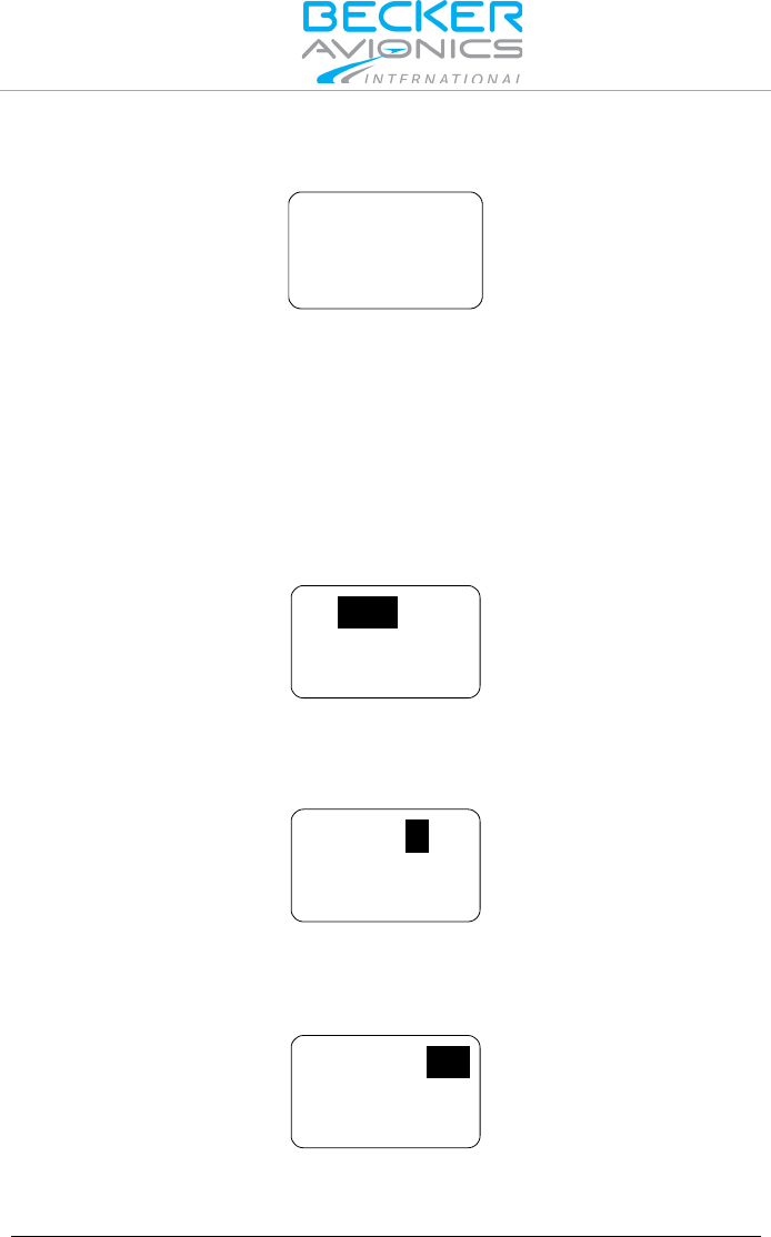
2.5.1. Standard Mode
Press the "MDE" key until the standard mode page appears.
The standard mode page displays the active frequency in the top line and
preset frequency in the bottom line.
118.005
127.000
IC
SQL
Changing the active frequency is not possible in standard mode (only
available in direct tune mode) but changing the preset frequency is
possible.
Operating Instructions
Frequency Selection Modes
0638.420-071 Issue 03 July 2015 VHF Transceiver Family 620X 15
Changing the preset frequency in standard mode:
• Make a "short press" on the "ROTARY ENCODER" for
modification of the 100 MHz digits.
Rotate the "ROTARY ENCODER" clockwise/counter clockwise
to change the frequency in 1 MHz steps.
118.005
128.000
SQL
• Make another "short press" on the "ROTARY ENCODER" for
modification of the 100 kHz digits.
Rotate the "ROTARY ENCODER" clockwise/counter clockwise
to change the frequency in 100 kHz steps.
118.005
128.000
SQL
• Make another "short press" on the "ROTARY ENCODER" for
modification of the 25/8.33 kHz digits.
Rotate the "ROTARY ENCODER" clockwise/counter clockwise
to change the frequency in 25/8.33 kHz steps.
128.000
SQL
118.005
Press the "STO" key to store the active frequency into the next vacant
memory place of the user channels database.
A short press of the "↨/SCN" key, exchanges active frequency to preset
frequency and vice versa.
Note: While the transceiver operates in transmit mode, the
toggle function is disabled.
Operating Instructions
Frequency Selection Modes
16 VHF Transceiver Family 620X 0638.420-071 Issue 03 July 2015
2.5.2. Direct Tune Mode
Press the "MDE" key until the direct tune mode page appears.
IC
SQL
118.005
BAT 13.5V
Note: The battery information is only displayed if BATTERY
VOLTAGE in the installation setup is selected.
In direct tune mode, the active frequency appears in the top line. It can be
edited by means of the "ROTARY ENCODER" following the procedure.
Changing the active frequency when in direct tune mode;
• Make a "short press" on the "ROTARY ENCODER" for
modification of the 100 MHz digits.
Rotate the "ROTARY ENCODER" clockwise/counter clockwise
to change the frequency in 1 MHz steps.
IC
SQL
118.005
• Make another "short press" on the "ROTARY ENCODER" for
modification of the 100 kHz digits.
Rotate the "ROTARY ENCODER" clockwise/counter clockwise
to change the frequency in 100 kHz steps.
IC
SQL
118.005
• Make another "short press" on the "ROTARY ENCODER" for
modification of the 25/8.33 kHz digits.
Rotate the "ROTARY ENCODER" clockwise/counter clockwise
to change the frequency in 25/8.33 kHz steps.
IC
SQL
118.005

Operating Instructions
Frequency Selection Modes
0638.420-071 Issue 03 July 2015 VHF Transceiver Family 620X 17
Note:
• The changes become active immediately
• Changing the active frequency is possible only when the
transceiver is not transmitting.
Press the "STO" key to store the active frequency into the next vacant
memory place of the user channels database.
2.5.3. Channel Mode
The channel mode shows data from User Channels Database (indicated by
"CH"), or Last Channels Database (indicated by "LAST") and shows if
applied a customized label (identifier) for the channels
(max. 10 characters).
The channel database provides storage of:
• CH01 to CH99 and
• LAST 1 to LAST 9.
Note The functions "LAST" and Store/Restore are only
available if these options are activated in
"Configuration Settings" - "MEM OPTIONS".
Note: If the device is operating in the 25 kHz mode a
selection of an earlier stored 8.33 kHz channel is not
possible. For selection of 8.33 kHz channels, the
device must operate in 8.33 + 25 kHz mixed mode.
Press the "MDE" key the channel mode page appears.
By means of channel number stored frequencies can be selected. The top
line shows the corresponding frequency and the bottom line the channel
number and customized label (identifier).
If the active frequency has no assigned channel number the indication is
"CH--".
IC
SQL
125.875
CH
TWR EDSB 01
IC
SQL
125.875
LAST
TWR EDSB 1

Operating Instructions
Frequency Selection Modes
18 VHF Transceiver Family 620X 0638.420-071 Issue 03 July 2015
2.5.3.1. Select/Deselect Channels:
Example: With CH01 user channel shown on display:
In order to select the channel number:
• The first turn clockwise in channel mode provides navigation
up user channels CH01 to CH99.
• Make a short press of the "ROTARY ENCODER", or:
• Make one clockwise turn of the "ROTARY ENCODER".
The channel number is now highlighted, the channel can be changed
turning the "ROTARY ENCODER". At each step the receiver tunes
immediately to the displayed frequency.
• The first turn counter-clockwise will enter to the channel
"LAST 1.
The channel number is now highlighted and one of the nine last used
channels is selectable by turning the "ROTARY ENCODER" either counter
clockwise or clockwise.
The "LAST" mode is left automatically after a 5 second timeout or can be
deselected by repeated pressing of the "ROTARY ENCODER".
When leaving the "LAST" channel database and the last shown frequency
is not stored in the User channel database, "CH__" appear on the display.
Press "STO" to start the storage process.
Leave Channel Mode:
Press the "MDE" key the standard page appears.
2.5.4. Frequency Storage Functions
Start store function by pressing:
• "STO" key in "Standard Mode", "Direct Tune Mode" and "SCAN
Mode".
During this procedure, the display looks similar to the channel
mode with one difference that "STO" appears on the left side of the
display.
• "ROTARY ENCODER" key in "Channel Mode"

Operating Instructions
Frequency Selection Modes
0638.420-071 Issue 03 July 2015 VHF Transceiver Family 620X 19
2.5.4.1. Store/Restore
The transceiver provides two databases:
• User channels database - provides 99 channels CH01 to CH99
to store frequencies with the possibility to apply a customized
label (identifier) max. 10 alphanumeric characters.
• Last channels database - automatically stores 9 last used
frequencies with customized identifier if applied, easy to recall
as LAST 1 to LAST 9.
Any frequency can be assigned to any channel within the range from
118.000...136.9916 MHz by simply pressing the "STO" button. All
99 channels are editable. By entering the storage procedure, the device will
first propose the next free channel for storing the active frequency. The
label "FREE" appears together with the channel number, if the selected
channel is vacant. A selected channel with an already stored frequency,
has the label "USED".
If the same frequency is stored a second time, then the existing data
(frequency, label/identifier data) is offered to store. If the frequency has no
label attached, ten underscore digits allows inserting a label. The cursor
automatically appears on the first position.
The data can be stored:
• to next free channel (offered from system).
• to a selected free channel.
• to a selected used channel (the existing data will be replaced).
STOCH
FREE
09
125.875
STO 09
CH
USED
125.875
STO
_ _ _ _ _ _ _ _ _ _
125.875
STO
TWR EDSB _ _
125.875
Label (Identifier) Data:
By turning the "ROTARY ENCODER" characters can be selected.
Selection works in both directions (example: A...Z0...9—
/blankA" by turning clockwise and vice versa by turning counter
clockwise).

Operating Instructions
Frequency Selection Modes
20 VHF Transceiver Family 620X 0638.420-071 Issue 03 July 2015
Each "short press" on the "ROTARY ENCODER", the cursor is passed to
the next position. A short press of the "STO" key stores the label a long
press of the "STO" key clears the currently edited label. After storing the
transceiver returns back to the previous frequency selection mode.
If no action occurs in label editing mode within 7 seconds, the transceiver
returns to the previous frequency selection mode without storing the
frequency and label information.
Stored frequencies are recallable in Channel Mode (see "Channel Mode"
page 17).
2.5.5. Automatic Storage Function
The transceiver stores 9 recently selected frequencies and updates the last
channels database during operation in "Standard Mode", "Direct Tune
Mode" and "Scan Mode".
When changing to a new active frequency, the previous active frequency is
stored "LAST" in memory LAST 1. The frequencies previously located in
LAST 1…LAST 8 are shifted to memory channels LAST 2…LAST 9. This
algorithm ensures the last 9 used active frequencies are available. Last
used frequencies "LAST" can be recalled in channel mode (see "Channel
Mode" page 17).
Note The functions "LAST" and Store/Restore to channels
are only available if these options are activated in
"Configuration Settings" - "MEM OPTIONS".
2.5.5.1. Delete data:
The stored content in User Channel Database can only be deleted in
"Configuration Settings". Please note the whole channel database will be
reset.
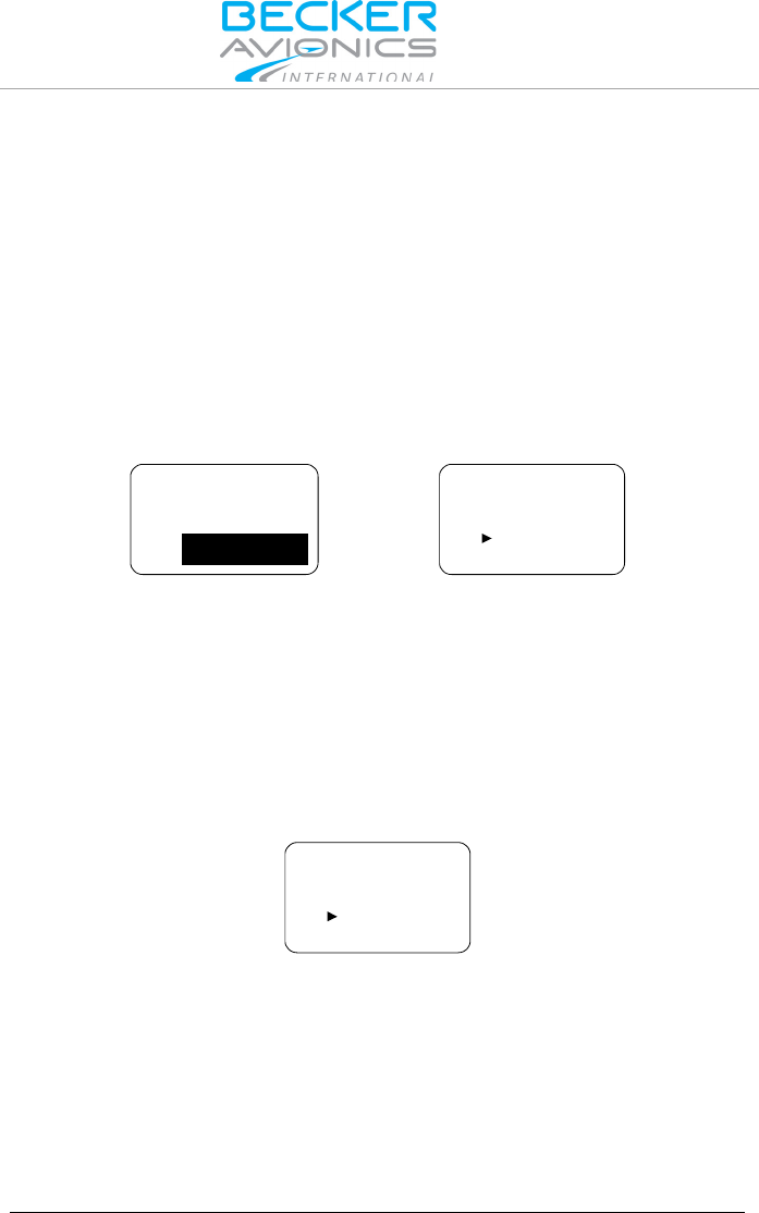
2.5.6. Scan Mode
In Scan Mode the display shows both the active frequency on the top line
and the preset frequency on the bottom line. The SCAN sign in the display
indicates that scan function is active.
118.005
127.000
SQL
SCAN
Operating Instructions
SQUELCH
0638.420-071 Issue 03 July 2015 VHF Transceiver Family 620X 21
In all frequency selection modes;
• A long press of "↕/SCN" key activates the scan function and
changes to STANDARD MODE if activated from CHANNEL or
DIRECT TUNE mode.
• A short press on the "MDE" key or a long press on "SCN" key
terminates scan function. After leaving scan function, the
device will remain in standard mode.
The arrow sign "►" in front of the active frequency indicates that this
frequency is audible.
If both the active frequency and preset frequency simultaneously detect a
signal, the active frequency (top) takes priority. The preset frequency then
inverts and blinks.
127.000
118.005
SQL
SCAN
127.000
118.005
SQL
SCAN
If selected in the installation setup an audio notification "beep" tone
becomes audible in addition to the blinking preset frequency to indicate the
presence of an RX signal on the preset frequency.
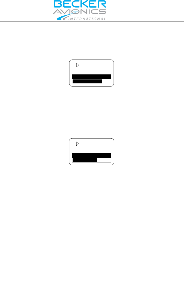
Reception on Preset Frequency in Scan Mode
If the preset frequency detects a signal while no signal is present on the
active frequency, the transceiver automatically switches over to the preset
frequency.
The arrow sign now appears in front of the preset frequency and the signal
is audible.
127.000
118.005
SQL
SCAN
Note: Transmission always uses the active frequency, even if
the monitored frequency is currently audible.
If TX on the preset frequency is required, push the
"↨/SCN" key to swap active and preset frequency.
2.6. SQUELCH
Independent of the selected operation menu, squelch can be toggled "ON"
or "OFF" by a short press on "SQL/IC" key.
Operating Instructions
Channel Spacing Mode
22 VHF Transceiver Family 620X 0638.420-071 Issue 03 July 2015
• If the squelch function is active ("ON") the receivers noise is
muted.
• If the squelch is "OFF" the arrow sign "►" in front of the active
frequency stay visible all the time and receiver noise will be
audible as long as signal is receiving.
127.000
118.005
SQL
127.000
118.005
SQL
Squelch "ON"
Squelch "OFF"
In the pilots menu, the squelch threshold is adjustable to a convenient
trigger level. See "Pilots Menu", page 28.
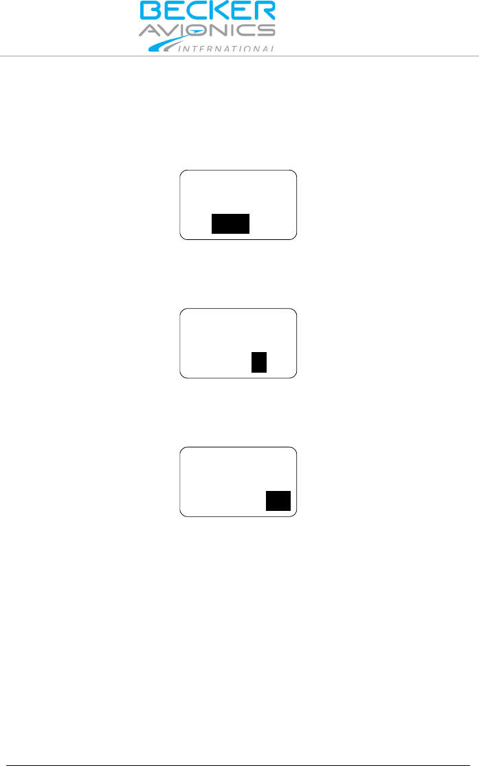
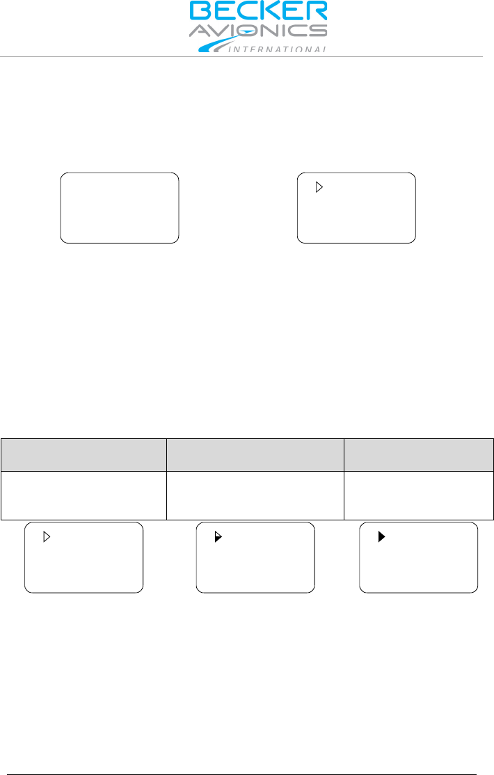
2.7. RX Field Strength Indication
The field strength indicator, represented by triangle on the left upper corner
of the corresponding frequency, will appear next to the active or preset
frequency in all frequency selection modes.
The field strength of an incoming signal relates to the measured RSSI level.
The three levels displayed are:
Weak Signal Strength
Good Signal Strength
Excellent Signal
Strength
RSSI passing squelch
levels
(empty triangle)
-88 > RSSI > -80 dBm
(half-filled triangle)
RSSI > -80 dBm
(fully filled triangle)
127.000
118.005
SQL
127.000
118.005
SQL
127.000
118.005
SQL
2.8. Channel Spacing Mode
The transceiver provides two operation modes of frequency channel
spacing, (8.33 and 25 kHz), selectable by means of pressing "STO" and
"MDE" keys simultaneously for at least 2 seconds.

Operating Instructions
Intercom Operation
0638.420-071 Issue 03 July 2015 VHF Transceiver Family 620X 23
In 25 kHz mode, 5 frequency digits are shown. Only operating frequencies
with a channel spacing of 25 kHz are selectable. If 8.33 kHz channels are
not in use, this mode provides the advantage of faster tuning since skipping
the 8.33 kHz frequency steps.
In 8.33 kHz and 25 kHz mixed mode 6 frequency digits are shown. The
transceiver tunes to all possible frequencies within the aviation VHF
frequency band. The channel spacing and operating frequency is derived
automatically from the selected and displayed frequency.
127.000
118.000
SQL
127.00
118.00
SQL
8.33 kHz channel spacing (left) / 25 kHz channel spacing (right)
Toggling between the frequency channel spacing modes is only available
for 620X-(0XX) variants. The 620X-(1XX) variants provide operation in
25 kHz Mode only.
2.9. Auxiliary Audio Input
The transceiver has a dedicated auxiliary audio input e.g. for MP3 player
connection.
With auxiliary input enabled in installation setup, the auxiliary audio input
signal mixing with the received signal from antenna (passing squelch) and
the intercom signal (when activated).
When intercom operates in ISOLATION mode, auxiliary audio input signal
is audible on headphone 2 output, even if radio communication
(transmission/receiving) is active.
AUX AUTO MUTE function depends on the AUX INPUT, selectable via the
CONFIGURATION page in the installation setup. This function
automatically mutes the audio signal from the auxiliary audio input as long
as the AR620X-(XXX) detects (based on squelch evaluation) a RX signal or
the user deactivates the squelch manually. If this function is disabled the
signal from the auxiliary audio input is permanently audible on the audio
output, independently of the received signal or the squelch status.
Automatic aux attenuation functionality controls the auxiliary audio input.
The level of the auxiliary input signal attenuates if intercom is activated by
VOX or by /IC discrete input. The auxiliary input signal reverts to its
previous value after intercom deactivation. The attenuation value can be
adjusted within the range from 0...40 dB.

Operating Instructions
Intercom Operation
24 VHF Transceiver Family 620X 0638.420-071 Issue 03 July 2015
2.10. Intercom Operation
Intercom operation may be triggered automatically via VOX (with adjustable
threshold) or externally via intercom switch.
The setting of VOX-threshold and intercom volume is accessible in the pilot
intercom menu, in tandem configuration on primary controller only.
For a single block, the primary controller is the one directly connected to
VHF transmitter. For a remote VHF transmitter the primary controller is the
one connected to primary control interface.
VOX-threshold and intercom volume for the second intercom circuit are
controllable from secondary controller RCU6201 (secondary controller is
the one connected to secondary control interface).
The transceiver has two internal built in intercom circuits. Therefore, up to
four headsets are connectable. Pilot and co-pilot connect to the first
intercom circuit. When intercom is active, both microphone signals are
mixed and amplified with each other and will be audible on both headphone
outputs. This enables internal communication via headsets between both
pilots. Passenger headsets are connecting to the second intercom circuit.
ALL mode - Everyone connected to the intercom will hear all
communications (pilots hear passengers and passengers hear pilots).
ISOL mode - Provides separate intercoms for the pilots (intercom circuit
one) and the passengers (intercom circuit two). This allows pilots to
communicate with each other, and air traffic, while the passengers are
isolated. The passengers on the intercom circuit two can hear auxiliary
audio (for example from mp3 player) and can communicate with each
other.
External "ISOL" input provides possibility to switch between ALL mode and
ISOL mode. If the /PTT1 input is active and ISOL is active the passenger
intercom operation on second intercom circuit is still possible.
While transmit mode intercom operation is degraded. During receive mode
the intercom operation activates automatically via VOX (with adjustable
threshold), or using the external intercom switch.
If intercom operation is active, the "IC" sign appears in the display.
118.005
127.000
IC
SQL
Operating Instructions
Intercom Operation
0638.420-071 Issue 03 July 2015 VHF Transceiver Family 620X 25
Intercom Operation via VOX
Via VOX, the intercom operation is automatically activated (threshold
adjustable in the intercom menu). With additional RCU6201, VOX threshold
for the first intercom circuit is adjustable from primary controller (AR620X or
RCU6201) and for the second intercom circuit from second controller
RCU6201.
Intercom activation via VOX is not possible if:
• It is enabled
• User switched the VOX off
In both cases, VOX is disabled and the display shows the sign to
indicate that activation via VOX is not possible.
118.005
127.000
IC
SQL
Intercom Operation via Intercom Switch
Via intercom switch (pin P1-7) independent of VOX or speaker status
(enabled/disabled) the intercom operation can be activated externally. The
external intercom switch has priority. During intercom operation the
speaker output is disabled.

Operating Instructions
Menus
26 VHF Transceiver Family 620X 0638.420-071 Issue 03 July 2015
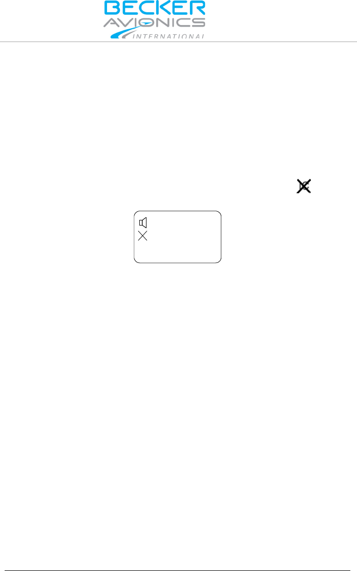
2.11. VOX & Speaker Operation
Depending on wiring and installation setup, the speaker may either always
been enabled, or the speaker can be enabled/disabled by switching
configurations using external switch /MIKE_SW.
When speaker enabled and not muted, the display will show the
loudspeaker sign.
118.005
127.000
IC
SQL
With active enabled speaker in audio configuration, VOX is always forced
to "OFF" and intercom via VOX is not possible (to avoid oscillation of VOX
due to acoustical feedback).
In transmission mode the speaker output is muted (switched "OFF") even if
speaker is enabled in current audio configuration in one of the following
cases:
• Intercom is activated by external intercom switch (I/C input).
• Power is below 10 V.
2.12. Menus
During normal operation in one of the frequency selection modes, the
following menus are available:
• The Intercom menu allows adjustment of intercom volume and
VOX threshold.
• The Pilots menu allows adjustment of panel brightness and
squelch threshold.
2.12.1. Intercom Menu
A long press (2 s) on "IC/SQL" key activates the intercom menu. In this
menu a short press on "IC/SQL" key provides toggling between the pages.
The intercom menu consists of two pages:
• IC VOLUME,
• IC VOX.
A long press on "MDE" key terminates intercom menu, otherwise the menu
automatically terminates after 5 seconds timeout.
Operating Instructions
Menus
0638.420-071 Issue 03 July 2015 VHF Transceiver Family 620X 27
Intercom Volume Menu
The active frequency is indicated in the top line of the display, the "IC
VOLUME" label and a bar graph with numerical value are show in the
bottom line.
IC VOLUME
40
IC 118.005
By means of the "ROTARY ENCODER", the intercom volume is
changeable from zero to 46. The intercom volume setting affects the
intercom audio and side tone signal, routed to the headphone.
The changes become active immediately.
Intercom VOX Menu
The active frequency is indicated in the top line of the display, the "IC VOX"
label and a bar graph with numerical value are shown in the bottom line.
IC VOX
6
IC 118.005
By means of the "ROTARY ENCODER" the intercom VOX threshold can
be changed from -30 (most sensitive, even a very low microphone signal
already triggers the VOX threshold for Intercom operation) to +10 (VOX is
less sensitive and only high microphone signals trigger the VOX threshold
for intercom operation).
Note: At a setting for VOX threshold of -15 a convenient
behaviour of the VOX should be achieved in most
aircraft. This requires that mike sensitivity had been
correct adjusted (installation setup). If the mike
sensitivity is incorrect adjusted, VOX may not work
satisfying.
By changing VOX threshold level to above +10, VOX switches "OFF". In
this case, "OFF" replaces the numerical value indication.
The changes become active immediately.

Operating Instructions
Menus
28 VHF Transceiver Family 620X 0638.420-071 Issue 03 July 2015
IC VOX
OFF
IC
118.005
With VOX switched "OFF", activation of intercom operation using the
external intercom switch (/IC discrete input) is still possible at any time. The
VOX threshold level is not adjustable if VOX forced to be "OFF" (due to
enabled speaker in current audio configuration).
In tandem installation the "first" controller adjust VOX threshold for first
intercom circuit, and the second controller RCU6201 adjust VOX threshold
for second intercom circuit.
2.12.2. Pilots Menu
Press the "MDE" key for 2 seconds to start the pilots menu. Toggling
between the pages by a short press of the "MDE" key, or by a short press
of the "ROTARY ENCODER".
The pilots menu consists of two pages:
• BRIGHTNESS.
• SQUELCH TRH,
To exit the pilots menu either
• Wait 5 seconds without any switch selections.
• Press the "MDE" key again for 2 second,
• Press the "ROTARY ENCODER" when the SQUELCH setting
page is visible,
BRIGHTNESS
The active frequency appears in the top line of the display "BRIGHTNESS"
label appears in combination with a bar graph and the selected value.
BRIGHTNESS
96
IC 118.005
The panel brightness for display illumination and push buttons can be
changed from 0 (illumination off) to 100 (maximum brightness) by turning
the "ROTARY ENCODER".

Operating Instructions
Menus
0638.420-071 Issue 03 July 2015 VHF Transceiver Family 620X 29
Note: This page is not available if in installation setup the
dimming input is set to 14 V or 28 V. For this setting,
the aircraft dimming circuit controls the brightness
parameters.
SQUELCH
A short press on the "ROTARY ENCODER" provides "SQUELCH" trigger
level adjustment. The active frequency appears in the top line of the
display. On the bottom line "SQUELCH" with bar graph and value is
indicated.
SQUELCH
10
IC 118.005
By means of the "ROTARY ENCODER", the squelch threshold is
adjustable:
• At a setting to 6 (very weak signals are audible with high noise
content; squelch opens at about -105 dBm).
• At a setting to 26 (only quite strong signals are audible with low
noise content; squelch opens at about -87 dBm). With this
adjustment the receiver sensitivity is significant reduced.

Operating Instructions
Warning and Failure Indications
30 VHF Transceiver Family 620X 0638.420-071 Issue 03 July 2015
2.13. Warning and Failure Indications
Display Contents
Description
LOW BATTERY
IC
118.005
Appear in 3-second
cycle
"LOW BATT" is indicated if the supply voltage of the
transceiver is below the threshold defined in the
installation setup.
The transceiver is still operable but may have a
reduced performance depending on supply voltage.
Possible reasons:
Accumulator capacity problems (gliders),
Power interrupts,
General power supply problems,
Setting for low battery threshold too high
STUCK PTT
IC 118.005
Appear in 3-second
cycle
"STUCK PTT" is indicated after 120 seconds of
continued transmission. The transceiver goes back
to receive mode even if the PTT line is still active
(GND).
For initiating a new transmission, the PTT line needs
first to become inactive (open).
Possible reasons:
Transmission lasts more than 120 seconds.
PTT-key is stuck.
PTT line permanently grounded (short circuit in
installation).
TX HOT
IC 118.005
Appear in 3-second
cycle
"TX HOT" is indicated if the internal device
temperature exceeds +90 °C.
Transceiver is still operable. Performance of
transmitter is reduced.
Possible reasons:
Very hot environmental temperature, long
transmissions times and insufficient airflow
conditions.
FAILURE
IC 118.005
Appear in 3-second
cycle
The transceiver has detected an internal failure
during normal operation.
Depending on failure reason, the device may still be
operable with degraded performance, or not
operable at all.
Possible reasons:
Specified environmental conditions
HW or SW failure inside the transceiver.
Contact maintenance shop for assistance.
Operating Instructions
Warning and Failure Indications
0638.420-071 Issue 03 July 2015 VHF Transceiver Family 620X 31
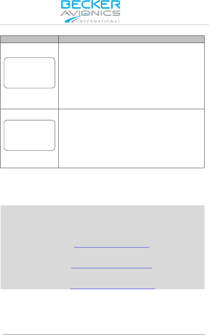
Display Contents
Description
FAILURE
PRESS ANY KEY
The transceiver has detected an internal failure
during start up.
Depending on failure reason, the device may be still
operable with degraded performance or not
operable at all.
Possible reasons:
Outside specified environmental conditions
HW or SW failure inside the transceiver.
Contact maintenance shop for assistance.
FAILURE
The transceiver has no communication with the
controller.
Depending on failure reason, the device may be still
operable with degraded performance or not
operable at all.
Possible reasons:
Problem with inter-wiring
Contact maintenance shop for assistance.
In case of additional questions contact your local BECKER dealer or
forward your request direct to BECKER "Product Support Department".
In the event of damage or a defect, the entire device must be returned for
repair. The repair must be made by trained BECKER personnel.
Becker Avionics GmbH • Baden-Airpark B108 • 77836 Rheinmünster
Germany
+49 (0) 7229 / 305-0 • Fax +49 (0) 7229 / 305-217
Customer Service:
Sales
Email: sales@becker-avionics.com
Support in German or English
Email: support@becker-avionics.com
Support in French
E-Mail: FR-sales@becker-avionics.com

Index
32 VHF Transceiver Family 620X 0638.420-071 Issue 03 July 2015
3. Index
Abbreviations ................................ 3
Activation of Intercom Operation via
Intercom Switch ......................... 25
Activation of Intercom Operation via
VOX ........................................... 25
Additional Conditions of Utilization 6
ALL mode ................................... 24
Automatic Storage Function ....... 20
Auxiliary Audio Input ................... 23
Bedien- und Anzeigeelemente ... 10
BRIGHTNESS ............................ 28
Changing the active frequency when
in direct tune mode .................... 16
Changing the preset frequency in
standard mode .......................... 15
Channel Mode ............................ 17
Conditions of Utilization ................ 6
Controls and Indicators ............... 10
Device Assignment ....................... 7
Direct Tune Mode ....................... 16
Frequency Selection Modes ....... 13
General Safety Definitions ............ 5
Intercom Menu ........................... 26
Intercom Operation ..................... 24
Intercom Volume Menu ............... 27
Intercom VOX Menu ................... 27
ISOL mode .................................. 24
List of Abbrevations ......................3
Menus ......................................... 26
Non Warranty Clause ....................6
Operation Instructions ...................7
Pilots Menu ................................. 28
Preset Frequency in Scan Mode . 21
Receive and Transmit Mode ....... 12
Receive Mode ............................. 12
RX Field Strength Indication ....... 22
Sales ........................................... 31
Scan Mode .................................. 20
Squelch ....................................... 21
SQUELCH .................................. 29
Standard Mode ........................... 14
Support ....................................... 31
Support in French ....................... 31
Transmit Mode ............................ 12
Units ..............................................4
VOX & Speaker Operation .......... 26
Warning and Failure Indications.. 30
Warranty Conditions .....................6
We reserve the right to make technical changes.
The data correspond to the current status at the time of printing.
*** End of the Document ***