Becker Avionics BXT6553 Mode S Transponder User Manual BXT6500 Series
Becker Avionics GmbH Mode S Transponder BXT6500 Series
UserManual.wiki
>
Becker Avionics
>
BXT6553 User Manual
Users Manual
Navigation menu
Upload a User Manual
Namespaces
Wiki Guide
HTML
PDF
Info
Views
User Manual
Discussion / Help
Navigation
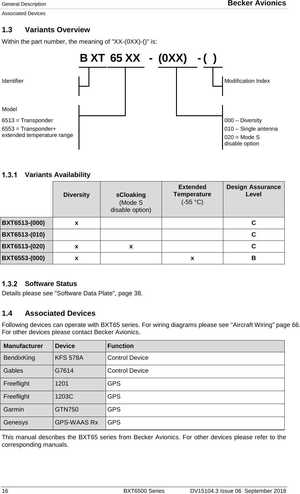
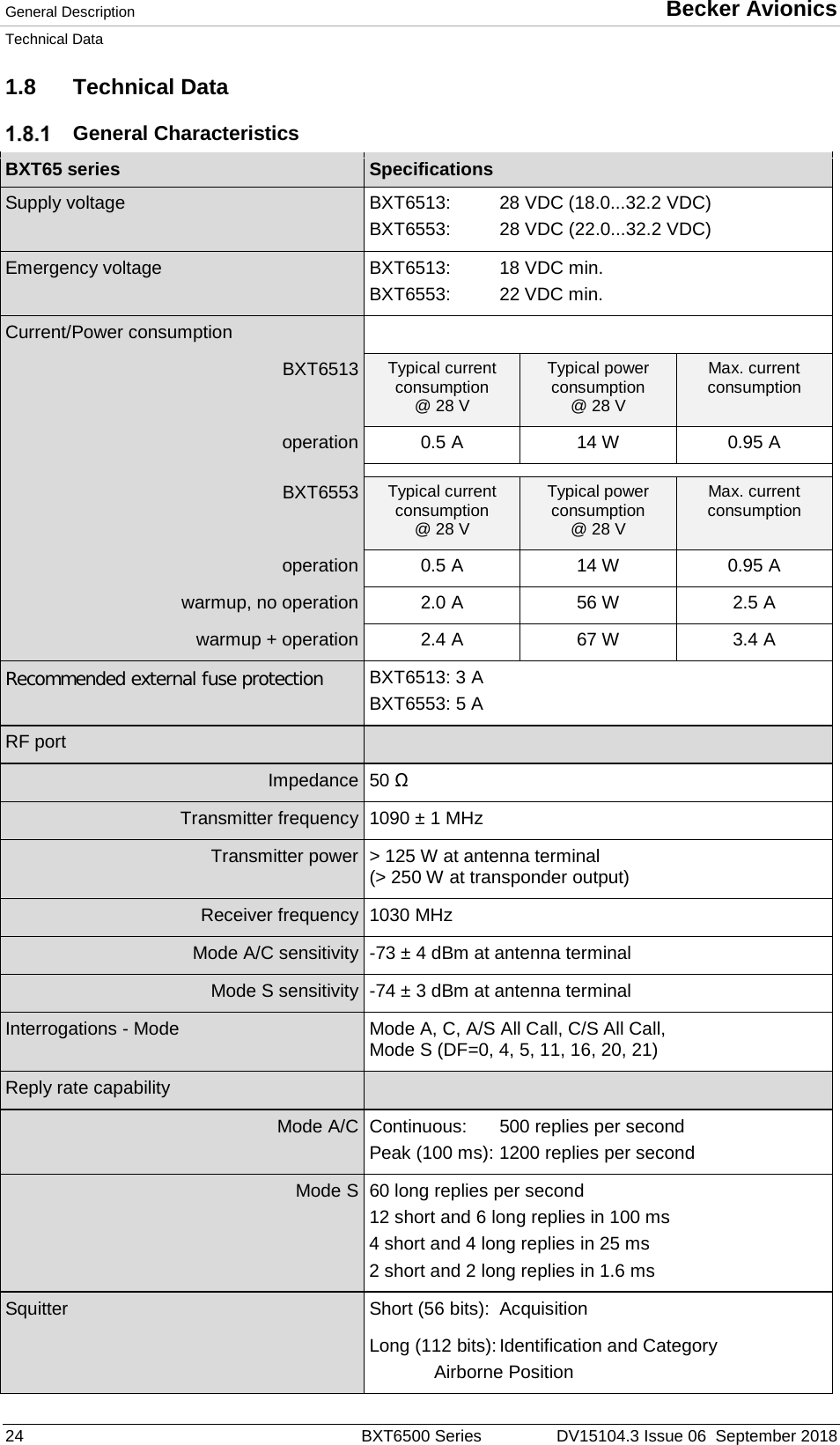
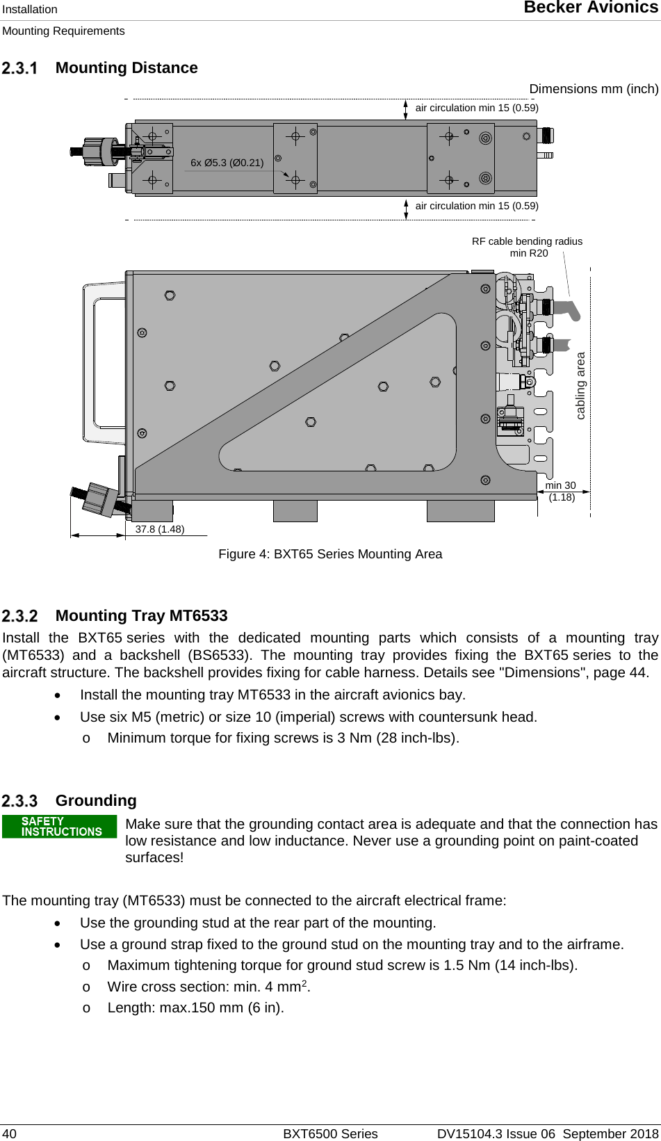
![Becker Avionics General Description Technical Data DV15104.3 Issue 06 September 2018 BXT6500 Series 31 1.8.8.1 FCC Approval Radiofrequency radiation exposure information: This equipment complies with FCC radiation exposure limits set forth for an uncontrolled environment. This equipment should be installed and operated with minimum distance of 50 cm between the radiator and your body. This transmitter must not be co-located or operating in conjunction with any other antenna or transmitter. NOTE: This equipment has been tested and found to comply with the limits for a Class A digital device, pursuant to Part 15 of the FCC Rules. These limits are designed to provide reasonable protection against harmful interference when the equipment is operated in a commercial environment. This equipment generates, uses, and can radiate radio frequency energy and, if not installed and used in accordance with the instruction manual, may cause harmful interference to radio communications. Operation of this equipment in a residential area is likely to cause harmful interference in which case the user will be required to correct the interference at his own expense. NOTE: This device complies with Part 15 of the FCC Rules [and with Industry Canada licence-exempt RSS standard(s)]. Operation is subject to the following two conditions: • This device may not cause harmful interference. • This device must accept any interference received, including interference that may cause undesired operation. NOTE: Changes or modifications made to this equipment not expressly approved by Becker Avionics may void the FCC authorization to operate this equipment.](https://usermanual.wiki/Becker-Avionics/BXT6553/User-Guide-4109867-Page-31.png)