Becker Avionics RT320911 Aviation Communications Transceiver User Manual TIT E 03
Becker Flugfunkwerk GmbH Aviation Communications Transceiver TIT E 03
Contents
- 1. Manual for ATC 3401 Transponder
- 2. User Manual
User Manual

Installation and Operation
Manual DV 60602.03
Issue 1August 1997
BECKER FLUGFUNKWERK GMBH • Baden Airpark • P.O. Box 34
D-76549 Huegelsheim • Telephone 07229 / 305-0
VHF
Transceiver
RT 3209 - ( )

FIRST ISSUE AND CHANGES
Issue . . . . . 1 . . . . . August 1997
LIST OF EFFECTIVE PAGES
Page No.: Date : Page No.: Date :
Title
1 -I - 1-II
1-1 - 1-10
2-I - 2-II
2-1 - 2-8
08/97
08/97
08/97
08/97
08/97
© by Becker Flugfunkwerk
All rights reserved

Table of contents
Section IGENERAL DESCRIPTION Seite
1.1 Introduction 1-1
1.2 Purpose of equipment 1-1
1.3 General description 1-2
1.4 Variants survey 1-3
1.5 Technical data 1-3
1.5.1 Power supply 1-3
1.6 General data 1-4
1.6.1 Dimensions Weight, Fuse 1-4
1.6.2 Receiver data 1-5
1.6.3 Transmitter data 1-6
1.7 Software 1-7
1.8 Approval and Regulations 1-7
1.9 Environmental Qualification Form 1-8
1.10 Scope of delivery 1-9
1.11 Accessories 1-9
RT 3209 - ( )
DV 60602.03/.04 Issue 08/97 Page 1-I

Blank
RT 3209 - ( )
Page 1-II DV 60602.03/.04 Issue 08/97

Section IGENERAL DESCRIPTION
1.1 Introduction
The following manual describes the VHF transmit/receiver RT 3209 - ( ). The manuals DV 60602.03
("Installation and Operation") and DV 60602.04 (Maintenance and Repair") contain the following
section :
Section DV 60602.03 DV 60602.04
1General Information X X
2Installation X X
3Operation X X
4Theory of operation X
5Maintenance and Repair X
6Illustrated Parts List X
7Modification and Changes X
8Circuit Diagrams x
1.2 Purpose of equipment
This remote-control VHF-transceiver RT 3209 - ( ) is controlled by a CU 5209 - ( ) control unit (or equal).
The transceiver enables voice communication on 760 channels in the 118.000 MHz to 136.975 MHz
range with a channel spacing of 25 kHz. It complies with the requirements of ICAO Annex 10 valid
from 01.01.1995.
RT 3209 - ( )
DV 60602.03/04 Issue 08/97 Page 1-1

1.3 General description
The transceiver is designed for installation in the avionics compartment.
The following are mounted on the connector end.
The equipment connector for connecting to the aircraft system.
The antenna socket for connecting the antenna.
The electronic system of the unit consists of the following circuit boards, which are connected to each
other by connectors.
l
1. Audio board
l
2 Connector board
l
3. Receiver board
l
4 Transmitter board
l
5. Processor board
The processor board is secured to the front panel by three bolts. The microcontroller as well as the
necessary storage and peripheral components are located on the processor board.
The VHF transceiver is fitted with a single superheterodyne receiver. A squelch (muting) circuit
suppresses transmitters or disturbances below a certain field strength. The switching threshold can
be set. The squelch function can also be switched off.
The transmitter is designed to be wideband over the 118.000 MHz to 136.975 MHz range. The sidetone
is automatically switched to the headphone output during transmission.
The oscillator frequency of the receiver and the transmitting frequency of the transmitter are generated
by a VCO (voltage controlled oscillator). This is monitored by a digital frequency evaluation circuit.
This digital frequency processing operates in conjunction with a microprocessor.
The microphone inputs are designed for parallel both dynamic and standard microphones. The inputs
are connected to a dynamic volume compressor which keeps the modulation voltage constant over a
wide input voltage range.
Aircraft internal communication is possible in the IC (intercom) mode. Activation is by means of an
external IC button (or switch) which is to be connected to the equipment connector.
The AF auxiliary input enables AF signal switching of auxiliary units in the aircraft. The switched
AF signals can, however, only be monitored in the reception mode.
RT 3209 - ( )
Page 1-2 DV 60602.03/04 Issue 08/97

Special functions
The transceiver contains some special functions which can be set in the service mode in
conjuntion with the control unit CU 5209 - ( ).
l
The squelch sensitivity, IC, sidetone and audio external input volume
l
The frequency setting can be inhibited. The transceiver then operates only on the
frequencies stored in the storage channels.
l
The storage of frequencies in the storage channels can be inhibited.
l
Access to the service mode can be interlocked with a 4-digit password.
1.4 Variants survey
Type designation Part No.: Transmitter output Power supply voltage
RT 3209 - (11)
60602-0000.000
0505.668-910 ≥ 6,5W
≥ 10W
13,75V
27,5 V
1.5 Technical data
1.5.1 Power supply
Nominal supply voltage 13.75 V.d.c.
Supply voltage range 12.4 V to 15.1 V
Emergency operation (10.0 V) Good intercom
or
Nominal supply voltage 27.5 V.d.c.
Supply voltage range 24.8 V to 30.3 V
Emergency operation (20.0 V) Good intercom
Power consumption
Standby" reception mode ≤ 100 mA
Reception mode ≤ 530 mA
Transmission mode ≤ 2.5 A
RT 3209 - ( )
DV 60602.03/04 Issue 08/97 Page 1-3

1.6 General data
Frequency range 118.000 MHz to 136.975 MHz
Number of channels 760
Channel spacing 25 kHz
Storage temperature range -55°C to +85°C
Operating temperature range as per
EUROCAE/RTCA ED-14C/DO-160C -20°C to +55°C short-time +70°C
Operating altitude as per
EUROCAE/RTCA ED-14C/DO-160C 50 000 ft
Vibration as per
EUROCAE/RTCA ED-14C/DO-160C Cat. NM
Humidity as per
EUROCAE/RTCA ED-14C/DO-160C Cat. A/ +50°C: 95%, 48 h
1.6.1 Dimensions Weight, Fuse
Front panel 139 mm x 50 mm
Depth of transceiver with mounting plate 253 mm
Weight 1,2 kg
Fuse internal 4 A automatic cut-out
RT 3209 - ( )
Page 1-4 DV 60602.03/04 Issue 08/97

1.6.2 Receiver data
Type of receiver Single superhetrodyne receiver
Sensitivity ≤ 5 µV EMF for 6 dB = SINAD
(mod. 1000 Hz/30%)
IF bandwidth ≥ ± 8 kHz at 6 dB attenuation
Selectivity ≥ 40 dB at ± 17 kHz
≥ 60 dB at ± 25 kHz
Squelch Can be adjusted and switched off
AGC characteristic for
5 µV to 100 mV EMF ≤ 6 dB
Distortion m = 85% ≤ 15%
Audio frequency response ≤ 6 dB 350 Hz to 2500 Hz
relative to 1000 Hz ≥ 18 dB at 4000 Hz
Intermediate frequency 21.4 MHz
Rated output
for speaker operation
at 13.75 V nominal operatingvoltage ≥ 3 W into 4 Ω
at 10.0 V operating voltage (emergency mode) ≥ 1.5 W into 4 Ω
with headset connected
at 13.75 V nominal operating voltage ≥ 100 mW at 600 Ω
at 10.0 V operating voltage (emergency mode) ≥ 30 mW at 600 Ω
Audio auxiliary input 1 V to 8 V at 600 Ω ± 10%
adjustable (regardless of volume)
RT 3209 - ( )
DV 60602.03/04 Issue 08/97 Page 1-5

1.6.3 Transmitter data
Transmitter output RT 3209 -(11) ≥ 10 W at 50 Ω
at 27.5 V nominal operating voltage ≥ 10 W at 50 Ω
at 20.0 V operating voltage
(emergency mode)
Transmitter output AR 3209 -(11) ≥ 6.5 W at 50 Ω
at 13.75 V nominal operating voltage ≥ 2 W at 50 Ω
at 10.0 V operating voltage
(emergency mode)
Frequency tolerance ≤ 15 ppm
Duty cycle 1:4 (Min)
Type of modulation A3E amplitude modulation
Modulation factor ≥ 70% to ≤ 99% (dynamic
compressor)
Distortion at 70% modulation ≤ 15%
Modulation bandwidth 350 Hz to 2500 Hz
Frequency response -6 dB (relative to 1 kHz/0 dB)
Input voltage (m = 70%)
Dynamic microphone ≤ 2 mV symmetrical 200 Ω
(dynamic compressor)
Standard microphone ≤ 120 mV 150 Ω
(dynamic compressor)
FM deviation with modulation
m = 70% f = 1.25 kHz ≤ 3 kHz
Sidetone true, adjustable
Automatic shutdown on short after 2 mins of continuous
circuit of transmit button transmission, the transmitter
shuts down. Activated by releasing
the transmit button and re-pressing.
RT 3209 - ( )
Page 1-6 DV 60602.03/04 Issue 08/97

1.7 Software
The frequency synthesizer and the frequency memory are controlled by a microprocessor.
The associated software was classified as software level 2 in accordance with the guidelines of
EUROCAE/RTCA document ED12A/DO-178A:
1.8 Approval and Regulations
LBA-No. 10.911/99JTSO
BAPT-No.: A133570J
Regulations
JTSO - 2C37d, ED-23A, Equipment Class 4
JTSO - 2C38d, ED-23A, Equipment Class C
EUROCAE/RTCA ED-14C/DO-160C
BAPT FTZ 17TR2010
Software EUROCAE/RTCA ED12A/DO-178A level 2
Environmental condition D1-BA(MN)XXXXXXZBABATAXXX
RT 3209 - ( )
DV 60602.03/04 Issue 08/97 Page 1-7

1.9 Environmental Qualification Form
The following performance standards under environmental test conditions have been established in
accordance with the procedures set forth in EUROCAE/RTCA Document No. ED-14C/DO-160C.
Environmental condition ED - 14C
DO - 160C
Category Performance
Temperature 4.0 D1
Low operating temperature 4.5.1 - 20° C
Low ground survival
(storage temperature)
- 55° C
High short-time opera-
ting temperature
4.5.2 70° C
High operating
temperature 4.5.3 + 55° C
High ground survival
(storage) temperature 85° C
Min. operating pressure
(equivalent altitude)
4.6.1 50.000 ft.
Temperature variation 5.0 B
Humidity 6.0 A48 hrs at up to 50° C and
95% relative humidity
Shock : 7.0
Operational shocks 7.2 11 ms at 6 G for all three
dimensional axes
Crash safety shocks 7.3 11 ms at 15 G for all three
dimensional axes
Vibration 8.0 MN
Magnetic effect 15.0 ZDeflection of 1° of compass at
a distance of ≥ 30 cm
Power input variation 16.0 BThe equipment functions on a
10-volt emergency power
supply
Resistance to voltage
spikes on equipment
power leads
17.0 A
Audio-frequency
conducted susceptibility
18.0 B
Susceptibility to induced
magnetic and electric •
fields at 400 Hz
19.0 A
Radio-frequency
interference
susceptibility
20.0 T
Spurious RF emissions 21.0 A
RT 3209 - ( )
Page 1-8 DV 60602.03/04 Issue 08/97

1.10 Scope of delivery
RT 3209 - (11) VHF transceiver Stock No. 0505.668-910
Operating instructions Stock No.
1.11 Accessories
Unit connection
Cable socket 25 pin Stock No. 0725.021.277
Connector housing Stock No. 0775.479-277
Antenna plug Stock No. 0725.706-277
Manuals
Installation and Operation Stock No. 0511.560-071
Maintenance and Repair Stock No. 0511.579-071
RT 3209 - ( )
DV 60602.03/04 Issue 08/97 Page 1-9

BLANK
RT 3209 - ( )
Page 1-10 DV 60602.03/04 Issue 08/97

Table of contents
Section II INSTALLATION Seite
2.1 General 2-1
2.2 Testing before installation 2-1
2.2.1 General 2-1
2.2.2 Visual examination 2-1
2.3 Mechanical installation 2-1
2.3.1 Mechanical installation of transceiver. 2-1
2.4 Installation wiring 2-2
2.4.1 General 2-2
2.4.2 Microphone connection 2-2
2.4.3 Speaker connection 2-2
2.4.4 Headphone connection 2-2
2.4.5 Intercom mode "IC connection". 2-3
2.4.6 Auxiliary" audio input 2-3
2.4.7 Setting the squelch sensitivity 2-3
2.4.8 Setting the sidetone volume 2-4
2.4.9 Internal automatic cut-out 2-4
2.5 Testing after installation 2-7
2.5.1 Ground test with engine shut down 2-7
2.5.2 Ground test with engine running 2-7
Fig. 2-1 Internal automatic cut-out 2-4
Fig. 2-2 Mounting dimensions transceiver 2-5
Fig. 2-3 Interwiring of the transceiver RT 3209 - ( ) with control unit CU 5209 - ( ) 2-6
RT 3209 - ( )
DV 60602.03/.04 Issue 08/97 Page 2-I

Blank
RT 3209 - ( )
Page 2-II DV 60602.03/.04 Issue 08/97

Section II INSTALLATION
2.1 General
The installation of the transceiver depends on the type of aircraft and its equipment. Therefore, only
general information can be given in this Section.
2.2 Testing before installation
2.2.1 General
Before installing the transceiver in an aircraft, inspect the unit for signs of transport damage.
2.2.2 Visual examination
Before commissioning, visually examine the unit paying particular attention to the following defects :
1. Dirt, dents, scratches, corrosion or broken attaching parts, damaged paintwork on housing, parts
of the housing .
2. Dirt or scratches on the identification plate, or inscriptions.
3. Dirt, bent or broken pins, displaced inserts of plugs and sockets.
2.3 Mechanical installation
2.3.1 Mechanical installation of transceiver.
The transceiver is designed for installation in an avionics compartment. To do this, the mounting plate
must first be secured to an appropriate point in the avionics compartment using five bolts. The
installation dimensions are given in Fig. 2-1. The transceiver is then pushed into the mounting plate
and locked in place by two quick-release bolts.
RT 3209 - ( )
DV 60602.03/04 Issue 08/97 Page 2-1

2.4 Installation wiring
2.4.1 General
The installation wiring is shown in Fig. 2-3.
(a) Use only cable which is fit for use in aircraft (self extinguishing). AWG 20 for power supply and
AWG 22 for other cables.
(b) Fit rubber sleeves over the solder joints on the equipment connector.
(c) Protect the power supply with a 7,5 A fuse or circuit breaker.
NOTE
The transceiver is protected internally by a 4 A fuse.
(d) No HF cables should be included in the cable harnesses of the system and the routing of connecting
cables alongside cables which carry audio power or pulses should also be avoided.
(e) Carefully check the wiring before switching on the unit and check particularly that (+) and (-) have
not been reversed.
2.4.2 Microphone connection
The transceiver enables a maximum of two dynamic microphones and two standard microphones (d.c.
supply) to be connected at the same time.
NOTE
The dynamic mike input sensitivity can be changed in the service mode.
2.4.3 Speaker connection
A 4 to 8 Ohm speaker can be connected to audio output P2- Pin 1 AF-asym.
CAUTION
The magnetic field of a speaker influences the magnetic compass. When choosing the
mounting point, a minimum distance of 1.3 m must be maintained between the speaker
and the magnetic compass.
2.4.4 Headphone connection
Up to two headphones with an impedance of 600 Ohm can be connected to the audio output P2 -
Pin 2 AF-HI/LO and Pin 3 AFLO.
RT 3209 - ( )
Page 2-2 DV 60602.03/04 Issue 08/97

2.4.5 Intercom mode "IC connection".
The intercom mode is designed for aircraft with a high noise level and assumes operation using
headsets. Additional wiring on the equipment connector with an IC switch is necessary (refer to
interwiring diagram).
The normal R/T communication takes place with the IC switch in the OFF position. When the IC switch
is set to ON, R/T communication can be carried on as before but intercommunication is also possible
between two crew members. The IC is switched off during transmission. The IC volume can be changed
in the service mode.
2.4.6 Auxiliary" audio input
The AF-AUX (P2 Pin 4) auxiliary audio input enables the switching of audio signals from other
equipment in the aircraft. The switched-in audio signals can, however, only be monitored in the
reception mode. The facility to switch two units together will be used particularly in those aircraft which
are fitted with a VHF transceiver and an NAV receiver. An audio input voltage of 1 to 8 V, 600 Ohm is
necessary for modulation of the audio amplifier (can be adjusted in the "Service" mode).
2.4.7 Setting the squelch sensitivity
The sensitivity of the squelch can be directly set on the VHF transceiver at any time in the SqL function
service mode.
RT 3209 - ( )
DV 60602.03/04 Issue 08/97 Page 2-3
2.4.8 Setting the sidetone volume
The sidetone volume can be directly set on the transceiver at any time in the SIDE function service
mode.
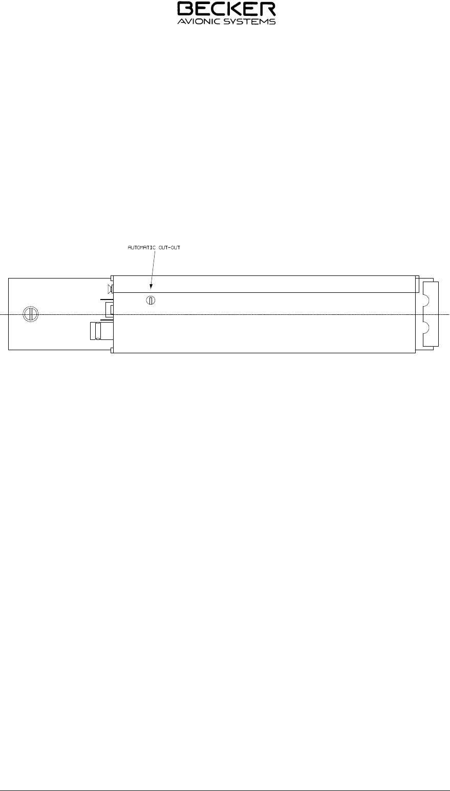
2.4.9 Internal automatic cut-out
The transceiver is fitted with an automatic cut-out . The released automatic cut-out is reactivated by
means of a peaked object.
Fig. 2-1 Internal automatic cut-out
RT 3209 - ( )
Page 2-4 DV 60602.03/04 Issue 08/97
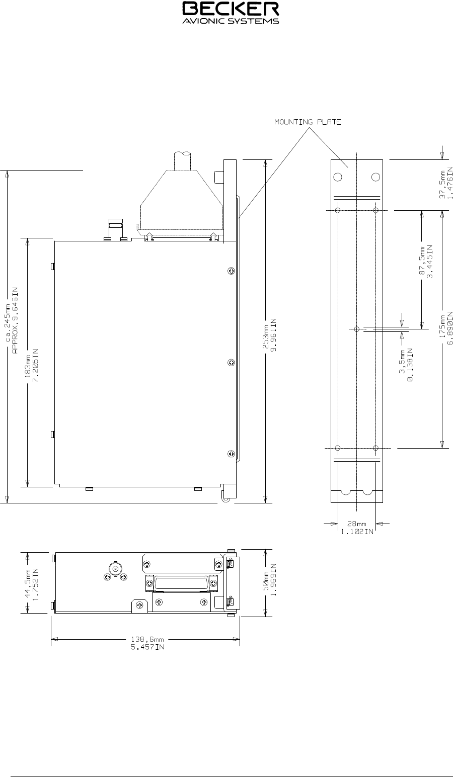
Fig. 2-2 Mounting dimensions transceiver
RT 3209 - ( )
DV 60602.03/04 Issue 08/97 Page 2-5
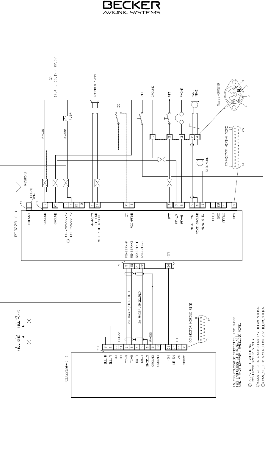
Fig. 2-3 Interwiring of the transceiver RT 3209 - ( ) with control unit CU 5209 - ( )
RT 3209 - ( )
Page 2-6 DV 60602.03/04 Issue 08/97

2.5 Testing after installation
2.5.1 Ground test with engine shut down
(a) After installation of the unit, measure the antenna tuning between the base of the antenna and the
antenna connecting cable using a VHF reflection-coefficient meter (voltage standing wave meter).
(b) The VSWR (voltage standing wave ratio) over the complete frequency range of the unit shall be
within 3:1. If this matching value is incorrect, this indicates a mismatch, caused for example by an
incorrect or unsatisfactory counterpoise, a cable with an impedance which deviates significantly
from 50 Ohm or an incorrectly tuned antenna.
(c) After the antenna measurement, check the readability by carrying out a speech test with a ground
station.
2.5.2 Ground test with engine running
(a) With the engine running at cruising speed check that the aircraft power supply is within the
permissible tolerances.
(b) When performing the succeeding speech test, ensure that the distance from the ground station is
as great as possible, at least 100 m. With the engine at cruising speed, the cabin noise of the
aircraft should be only slightly transmitted and communication should be clear and distinct. Hold
the microphone close to the lips when speaking.
(c) Switch on the aircraft intercom using the IC switch (if fitted) and carry out a speech test with the
engine running at cruising speed. If necessary, adjust the IC volume (refer to the service mode in
the operating instructions (section 3)).
(d) Switch on the squelch switch and check the squelch function. The point at which the squelch
operates is set in the service mode (refer to operating instructions, section 3).
RT 3209 - ( )
DV 60602.03/04 Issue 08/97 Page 2-7

Blank
RT 3209 - ( )
Page 2-8 DV 60602.03/04 Issue 08/97