Becker Avionics RT6512 Aviation VHF AM Transceiver User Manual RT6512
Becker Flugfunkwerk GmbH Aviation VHF AM Transceiver RT6512
UserManual.wiki
>
Becker Avionics
>
RT6512 User Manual
Installer Instructions
Navigation menu
Upload a User Manual
Namespaces
Wiki Guide
HTML
PDF
Info
Views
User Manual
Discussion / Help
Navigation


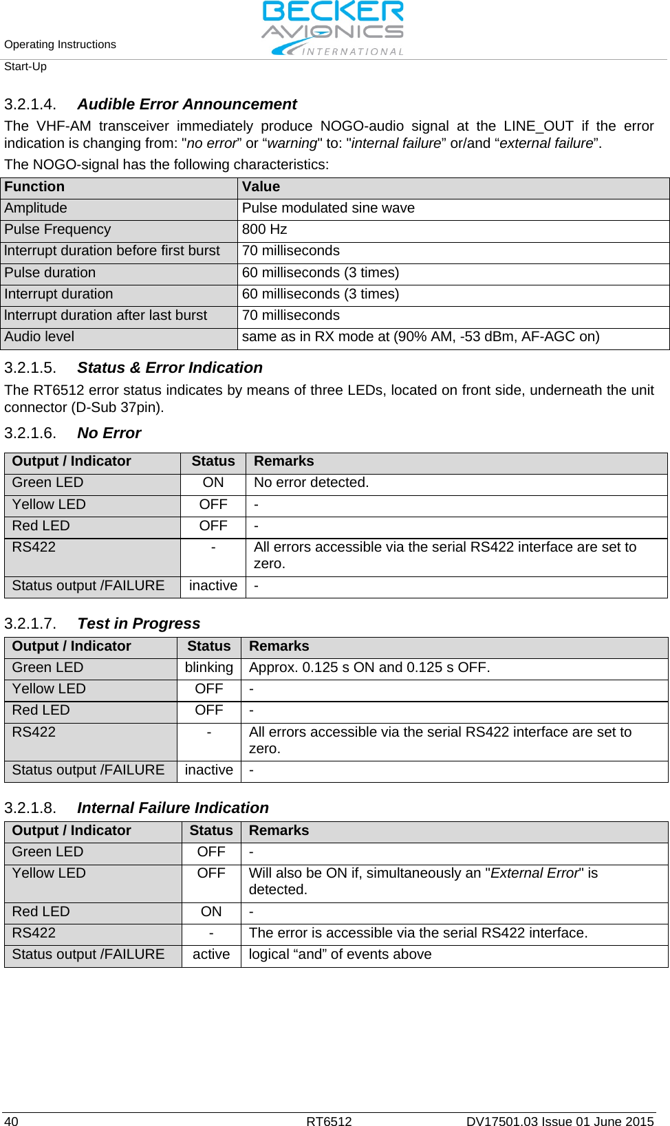
![Operating Instructions Start-Up 38 RT6512 DV17501.03 Issue 01 June 2015 The following functions are checked under BIT: • Power Supply (PSB Error) BIT function monitors internal Power Supply conditions. “PSB error” is classified as an "internal failure". • RCU Lost Connection Error If the VHF-AM transceiver does not receive any valid frame via the RS422 serial interface within each 5 seconds, then the “RCU Lost Connection Error” appears and classifies as “external failure”. If RT6512 is controlled by ARINC 429 interface, detecting “RCU Lost Connection Error” is blocked. • Channel Error If the VHF-AM transceiver receives an invalid channel name, then the "Channel Error" appears and classifies as ”external failure”. • RX Synthesizer Error The VHF-AM transceiver monitors the RX synthesizer(s). If any error behavior is detected, the “RX Synthesizer Error” indication appears and is classified as an internal failure. • RX AGC Error AGC voltage of the RX (RF-AGC) is monitored. If an error behavior is detected, the device indicate a "RX AGC Error" • TX Output Power Error In TX mode, the VHF-AM transceiver is monitoring the forward power at the antenna connector. If any error behavior is detected a “TX Output Power Error” indication appears and is classified as an "internal failure". As long as detecting the “TX Output Power Error”, the VHF-AM transceiver stays in RX mode. • TX Synthesizer Error The VHF-AM transceiver monitors the TX synthesizer while generating the TX signal. If error behavior is detected and the /PTT input is active (low), the VHF-AM transceiver indicates "TX synthesizer error" This error classifies as "internal failure". As long as detecting the "TX Synthesizer Error", the transmitter stays in TX-Off-condition. • TX OFF-Overtemp Error Figure 18 Thermal behavior for TX function The VHF-AM transceiver monitors the heat sink temperature. If the heat sink temperature exceeds +95 °C at the point of measurement and on the /PTT input a low state is detected, the VHF-AM transceiver indicates a "TX OFF-Overtemp Error". As long as the error is detected, the VHF-AM transceiver stays in TX-off-condition. The error indication disappears when the heat sink temperature has fallen below +85 °C at the point of measurement. This error is indicated as an "external failure". • TX Hot Error The VHF-AM transceiver is monitoring the heat-sink temperature. If the heat sink temperature exceeds +85 °C at the point of measurement and on the /PTT input a low state is detected, the VHF-AM transceiver indicates a "TX Hot Error". The error indication disappears when the heat sink temperature has fallen below +75 °C at the point of measurement. This error is indicated as a warning. 95 85 75 20 10 [W] [oC] no TX Off no TX Hot TX Off TX Hot TX Off TX Hot](https://usermanual.wiki/Becker-Avionics/RT6512/User-Guide-2935021-Page-38.png)
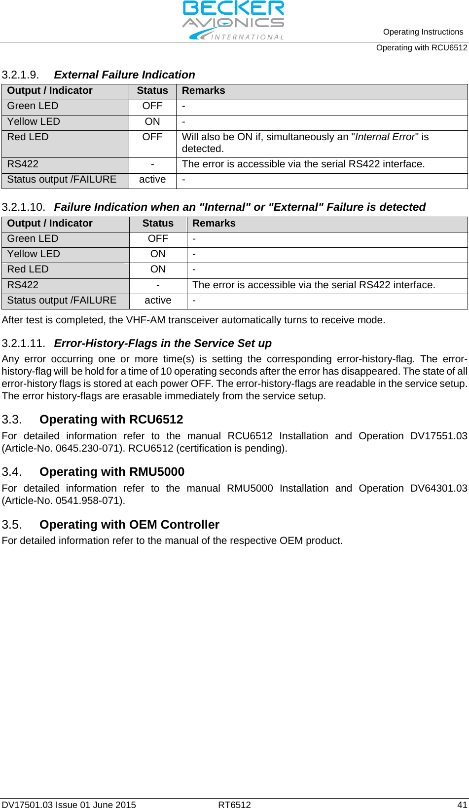
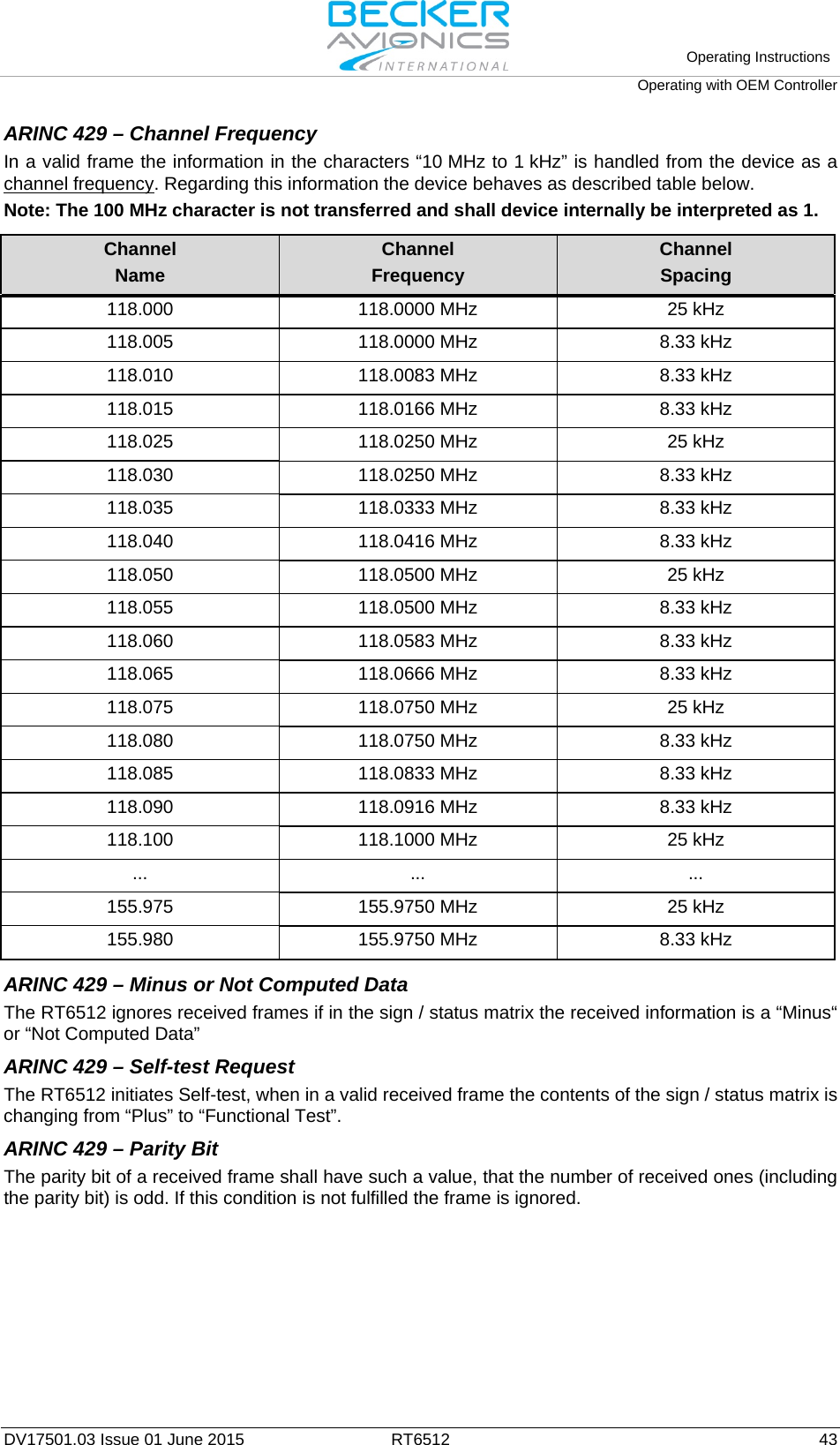
![Operating Instructions Operating with OEM Controller 42 RT6512 DV17501.03 Issue 01 June 2015 3.5.1. ARINC 429 Protocol supported by RT6512 The ARINC 429 Word Format (according to [ARINC 429]-Appendix-6). PARITY SIGN / STATUS MATRIX 10 MHz 1 MHz 100 kHz 10 kHz 1 kHz SDI LABEL (VHF COM) BIT No. 32 31 30 29 28 27 26 25 24 23 22 21 20 19 18 17 16 15 14 13 12 11 10 9 8 7 6 5 4 3 2 1 Example 1 0 0 0 1 0 1 0 0 0 0 1 0 1 0 0 1 1 0 0 0 0 0 0 0 0 0 1 1 0 0 0 Norm. Oper (2) (8) (5) (3) (0) all call (0) (3) (0) Note: The 100 MHz character is always 1 and because of this so a not transferred information ARINC 429 Bitrate The RT6512 operates with bitrate 12.0… 14.5 kilobits per second (LOW SPEED OPERATION). ARINC 429 Broadcasting The RT6512 periodically transmits a package consisting of the following frames: label 030/047 label 377 Each package is transmitted every 100…200 ms ARINC 429 – Accepted Labels When the label of a received frame is not equal to (030 or 047) then the complete frame is ignored. ARINC 429 – Label Selection for outgoing Frames The RT6512 transmits (broadcast) ARINC 429 label 030 when is tuned to 25 kHz spacing channel. The RT6512 transmits (broadcast) ARINC 429 label 047 when is tuned to 8.33 kHz spacing channel. The RT6512 uses label 030 with SSM bits set to No Computed Data when no valid data exists. ARINC 429 – CTRL Words Content The RT6512 accepts Active Frequency change and SQUELCH change commands. ARINC 429 – Supported Labels The RT6512 transmits frame 377 which includes Equipment ID. ARINC 429 – SDI for incoming ARINC Frames The RT6512 accepts received frame if the SDI does fulfil at least one of the following conditions: • The received SDI is equal to 00 (regardless of /COM2 input’s status) • The received SDI is equal to Bit10=0 Bit9=1 for Inactive (HIGH state) /COM2 input • The received SDI is equal to Bit10=1 Bit9=0 for Active (LOW state) /COM2 input Otherwise the device ignores the received frame. Note: The status of the /COM2 discrete input is monitored permanently (continuously). ARINC 429 – SDI for outgoing ARINC Frames The SDI fields in outgoing ARINC 429 frames are equal to: - Bit10=0 Bit9=1 for Inactive (HIGH state) /COM2 input - Bit10=1 Bit9=0 for Active (LOW state) /COM2 input Note: The status of the /COM2 discrete input is monitored permanently (continuously).](https://usermanual.wiki/Becker-Avionics/RT6512/User-Guide-2935021-Page-42.png)