Becker Avionics TG480 VHF/AM Transceiver User Manual TITEL 3
Becker Avionics, Inc. VHF/AM Transceiver TITEL 3
UserManual.wiki
>
Becker Avionics
>
TG480 User Manual
Installation and Operation
Navigation menu
Upload a User Manual
Namespaces
Wiki Guide
HTML
PDF
Info
Views
User Manual
Discussion / Help
Navigation

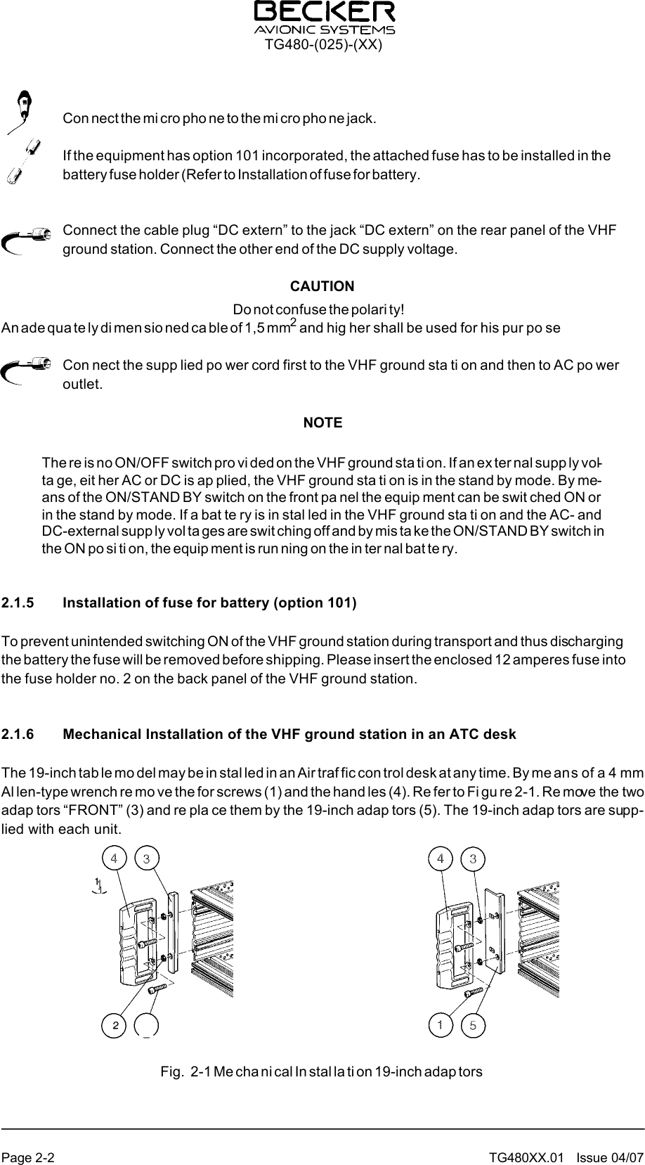
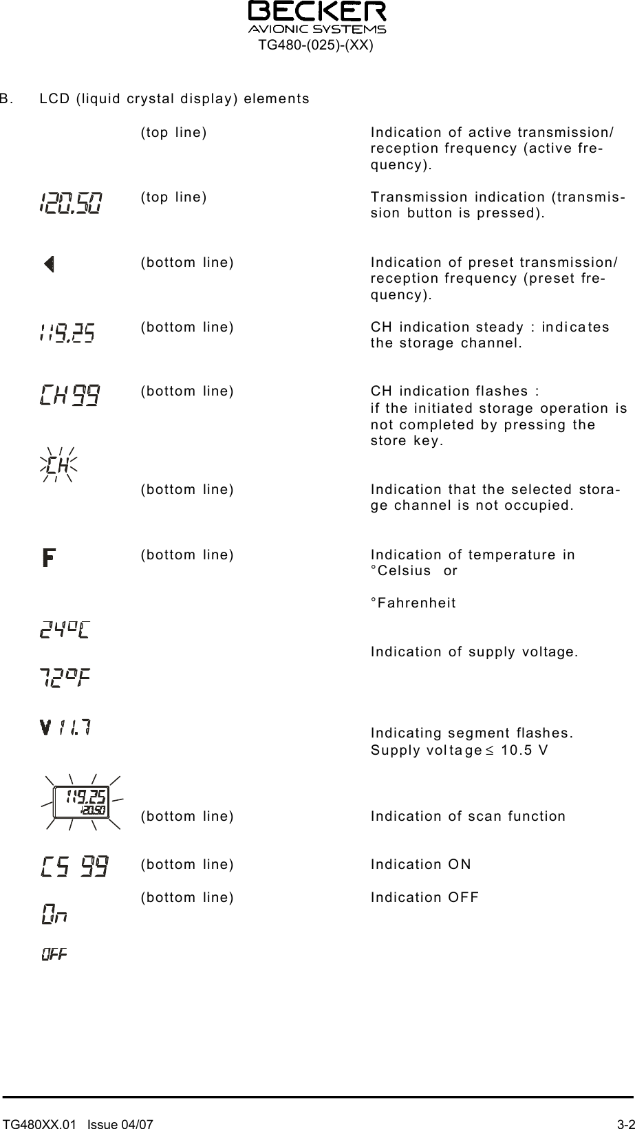
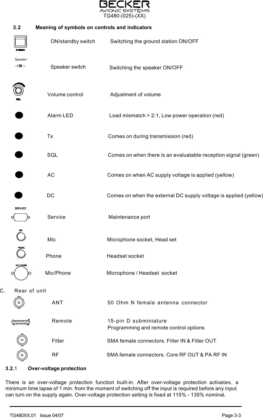
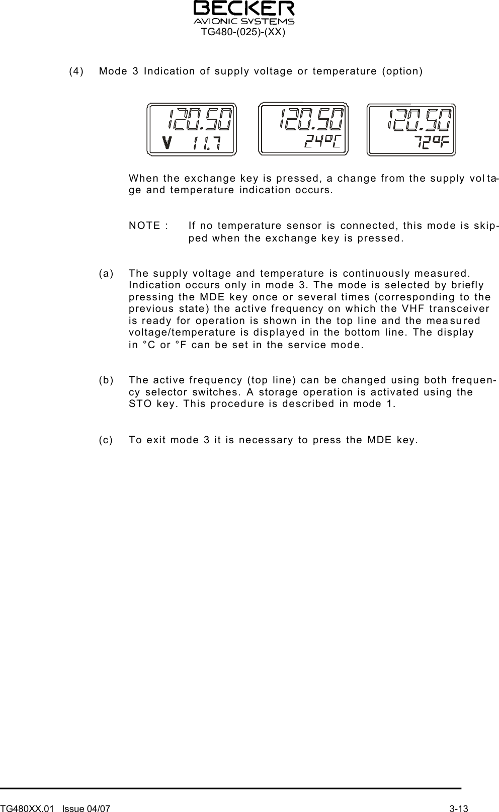
![Section 1 GENERAL INFORMATION1.1 IntroductionThis manual TG480XX.01 describes the VHF ground station TG480-(025)-(XX).The manual TG480XX.01 "Installation and Operation" contains the following sections :Section DV 480XX.011 General Information X2 Installation X3 Operation X1.2 Purpose of equipmentThe VHF ground station TG480-(025)-(XX) is a fixed ground station for speech communications in the VHF frequency range of 118.000 MHz to 136.975 MHz.The ground station is designed for airport and airfield use and can be used as a main transceiver on landing fields and as a standby unit on airports and for special tasks within the scope of air traffic control.1.3 General descriptionThe VHF ground station is designed for mounting in 19-inch rack systems or in an ATC desk.The VHF ground station is designed to operate on a AC supply voltage of 115 V or 230 V ± 10% /50-60 Hz. In DC operation, the VHF ground station is designed to operate on a voltage of 13.75 V [TG480 - (10) or 24V, TG480 - (20), TG480 -(50)].The control circuit switches over to external DC voltage if the AC voltage supply fails. If an internal battery is fitted to provide an emergency power supply, it will still be possible to maintain T/R communication for several hours if the AC and external DC supplies fail. The necessary charging circuit for the battery is located inside the TG480 - ( ). TG480-(025)-(XX)TG480XX.01 Issue 04/07 Page 1-1](https://usermanual.wiki/Becker-Avionics/TG480/User-Guide-981995-Page-5.png)