Beckett AFG User Manual BURNER Manuals And Guides L0805145
BECKETT Burner, Furnace Manual L0805145 BECKETT Burner, Furnace Owner's Manual, BECKETT Burner, Furnace installation guides
User Manual: Beckett AFG AFG BECKETT BURNER - Manuals and Guides View the owners manual for your BECKETT BURNER #AFG. Home:Heating & Cooling Parts:Beckett Parts:Beckett BURNER Manual
Open the PDF directly: View PDF ![]() .
.
Page Count: 66
FOR
THE
PROFESSIONAL
SERVICEMAN
to at
D_tt_buted
as (t,_z
iru4ustrtj
service b_
FOR
THE
PROFESSIONAL
SERVICEMAN
at
R/C,: Beckett Corporation
38251 Center Ridge Road
P.O. Box 1289
Elyria, Ohio 44036- !289
1-800_OIL BURN (645-2876)
R.W,BeckettCanada, Ltd.
Unit 3 - 430Laird Road
Guelph, Ontario, Canada NIG 3X7
1-800-665-6972
Copyright @ 1979, i997 RW, Beckett Corporation All rights reserved
Acknowledgements
R.W.BeckettCorporation is pleased to present this new,
revised edition of Guide to Oilheatfor the ProfessionalServiceman
(formerly known as The ProfessionalServiceman's Guide to
Oilheat Savings). This new edition has been expanded to include
updated information and several additional topics of importance
to the industry as we approach and enter the 21st Century.
These topics include direct, side-wall venting and outside
combustion air. We hope this new edition will help you achieve
greater success for your business while providing outstanding
service to your customers.
Beckett has distributed many thousands of copies of [his
book, in various editions, since its first printing in 1979.
The original ProfessionalServiceman's Guide to Oilheat Savings
was based primarily on material developed in 1978 by the
Massachusetts Better Home Heat Council and distributed by
them as a manual entitled Oil Heat Energy ConservationManual.
This material is gratefully used with their permission.
The Better Home Heat Council received finandal support for
development of this material through the Massachusetts Energy
Office, as part of the 1978 State Energy Conservation Plan, funded
by the U.S. Department of Energy under PL94-163 and 94-384.
BHHC also received technical assistance from the Walden Division
of Abcor, Inc., and from numerous individual members of
BHHCs Technical Review Committee.
Acknowledgements
VCewishto acknowledgeand thank the followingcompanies
and organizations (listedalphabetically)that suppliedillustrations,
photos, and/or information used in the revisededitionof thisbook:
Bacharach,Inc.
Broo'yahavenNationalLaboratory
DanfossAutomaticControls
DelavanInc.
FieldControls
HagoManufacturing
LynnProductsCo.
PetroleumMarketersAssociationofAmerica
$untecIndustriesIra:.
Testo,Inc.
Thermo-DynamicsBoilerCo.
TjernlundProducts,Inc.
Trianco-Heatmak_r,Inc.
Ifwe haveinadvertentlyleft anyoneoff this list,wesincerely
apologize,and assureyou that your contribution isvery
much appreciated.
TABLE OF CONTENTS
CHAPTER 1 COMBUSTION THEORY ................................................................................................. 1
Fuel Oil ............................................................................................................................. 1
Combustion ....................................................................................................................... 2
Role of Excess Air in Combustion .................................................................................... 4
Excess Air - Smoke Relationship ....................................................................................... 5
Effect of Air Leaks ............................................................................................................ 6
CtD_FrER 2 OILHEAT SYSTEMS ......................................................................................................... 7
Overview of Oilheat Systems ........................................................................................... 7
Basic Oil Burner Design ................................................................................................... 9
Nozzles ........................................................................................................................... 12
Combustion Chambers .................................................................................................... 14
Heat Exchangers ............................................................................................................. 18
Combustion Air Requirements ........................................................................................ 20
Draft ................................................................................................................................ 21
Draft Regulators .............................................................................................................. 22
Flue and Chimney Exhaust ............................................................................................. 24
"ventingMultiple Appliances ........................................................................................... 24
Alternative "ventingSystems ........................................................................................... 25
Power Chimney Venting ................................................................................................. 25
Side-Wall Venting ........................................................................................................... 25
Power Venting ................................................................................................................. 29
Direct Venting ................................................................................................................. 29
Sealed Combustion ......................................................................................................... 29
Outdoor Units ................................................................................................................. 29
CHAPTER 3 EFFICIENCY - DEFINITION OF VARIOUS TYPES OF EFFICIENCY .................. 30
Combustion Efficiency ...................... ............................................................................. 30
Steady_State Efficiency ................................................................................................... 30
AFUE Ratings ................................................................................................................. 30
CHAPTER 4 STEADY-STATE EFFICIENCY MEASUREMENTS ................................................... 32
Stack Loss Theory .......................................................................................................... 32
Measurement of Carbon Dioxide or Oxygen .................................................................. 36
Alternative Measurement Techniques ............................................................................. 38
Other Advanced Multi-Purpose Test Instruments ........................................................... 38
Measurement of Flue Gas %mperature .......................................................................... 39
Smoke Measurement ....................................................................................................... 40
Draft................................................................................................................................ 41
Carbon Monoxide Testing ............................................................................................... 42
CHAPTER 5RESIDENTIAL OIL BURNER ADJUSTMENTS ......................................................... 44
Facts About High CO 2 Levels ........................................................................................ 44
Procedure Preparation Steps ......................................................................................... 45
Combustion Adjustment Steps ........................................................................................ 46
Recording of Readings .................................................................................................... 47
The Annual Clean-Up ..................................................................................................... 47
Test Report Form ............................................................................................................ 49
Basic Troubleshooting .................................................................................................... 50
CHAPTER 6 ENERGY CONSERVATION OPTIONS ........................................................................ 52
Flame Retention Oil Burners .......................................................................................... 52
Criteria for Installing Name Retention Oil Burners ....................................................... 53
Installation of Matched BoileffBurner or Furnace/Burner Systems ................................ 55
LIST OF FIGURES
FIGURE PAGE
1 Viscosity vs. temperature, No. 2 fuel oil .......... 1
2 "viscosityconversion, Centistokes vs. Saybolt
Universal Seconds............................................. 1
3 Combustion products by weight and volume,
1 lb. fuel oil, 0% excess air...............................3
4 Combustion products by weight and volume,
1 lb. fuel oil, 50% excess air ............................. 3
5 Relationship between excess air and CO2 .......4
6 Effect of excess air on CO2 .............................. 5
7 Effect of excess air on combustion gas
temperature ........................................................ 5
8 Smoke & efficiency vs. excess air curve .......... 6
9 Typical oilheat system components .................. 7
10 Underground tank ............................................. 7
11 Above ground tank ............................................7
12 Indoor tank ........................................................ 8
13 Typical oil burner components ....................... 10
14 Burner air patterns ........................................... 10
15 Burner flame configurations ........................... 11
16 Cutaway view of a fuel oil nozzle .................. 12
17 Beckett Multi-Purpose Gauge ......................... 13
18 Nozzle spray patterns ...................................... !3
19 Combustion chamber design .......................... 14
20 Air tube insertion ............................................ 15
21 Soft fiber refractory combustion
chambers ......................................................... 16
22 Combustion chamber sizing data.................... t7
23 Recommended minimum inside dimensions
of refractory-type combustion chambers ........ 17
24 Heat exchanger designs .................................. !8
25 Oil furnace heat exchanger ............................. 19
26 Condensing furnace heat exchanger ............... 19
27 Approximate relationship of % excess air
with flame temperature and volume of
combustion cases ............................................ 19
28 Outside air combustion ...................................20
29 Tjernlund Combustion Air In-ForcerTM .......... 21
30 Draft changes in a chimney ............................ 22
31 Field draft controls .......................................... 23
32 Common chimney sizes vs. Btu input ............ 24
33 Multiple appliances vented separately ............ 24
34 Square inch area of flue collars ...................... 25
35 Tapered manifold vent system ........................ 25
36 Constant sized manifold vent system ............. 25
37 Barometric damper locations when venting
multiple appliances ......................................... 26
FIGURE
38
39
40
PAGE
Power chimney venting system ..................... 26
Efficiency vs. net stack temperature ............... 26
Common chimney troubles and
theircorrections ............................................... 27
41 Power side-wall venting.................................. 28
42 Field power venter .......................................... 28
43 Sealed combustion furnace and boiler ............ 28
44 Outdoor appliance installation ........................ 29
45 Distribution of heat as determined by the
stack loss method ............................................ 32
46 Theoretical combustion relationship between
CO2 and 0 2 for No. 2 heating oil .................. 33
47 CO2 gas analyzer ............................................ 34
48 Graph of heating appliance efficiency ............ 34
49 No. 2 fuel oil efficiency table ......................... 35
50 Construction of CO2 analyzer ........................ 36
51 Lynn Model 6500 Combustion Efficiency
Analyzer .......................................................... 38
52 Testo 342 Combustion Analyzer ..................... 38
53 Bacharach CA 40H Combustion
Analyzer .......................................................... 39
54 Flue gas thermometers .................................... 39
55 Bacharach smoke spot tester ........................... 40
56 Oil burner smoke scale.................................... 41
57 Draft measurement devices ............................. 41
58 Lynn Model 7400 Carbon Monoxide
Analyzer .......................................................... 42
59 CO level standards .......................................... 43
60 Flue pipe sampling hole locations .................. 44
61 Correlation of percent of CO2, 0 2 and
excess air ......................................................... 45
62 Typical smoke vs, CO2 percent ...................... 46
63 Test report form ............................................... 49
64 Name retention combustion heads ................. 52
65 Non-flame retention and flame retention
combustion ...................................................... 53
66 Recommended firing rates for Beckett AF
and AFG burners ............................................. 53
67 Beckett AF II air tube combination and
firing rate chart ................................................ 54
68 Air tube/head combinations for wet base
and wet leg boilers .......................................... 54
69 Name retention heads for furnaces,
dry base boilers, and water heaters ................. 55
70 Outdoor winter design temperatures............... 56
7t Nozzle manufacturers, spray patterns,
and capacities .................................................. 58
PurposeofManual
This manual has been prepared for use by oilheat
service managers and service technicians_
It provides a brief overview of oilheat systems,
as well as a review of basic oil burner combustion
theory. Included are suggested procedures for
adjusting and maintaining oil burners-and other
oilheat system components-to provide your
customers with maximum efficiency,comfort,
and safety.
Modification and installation procedures recom-
mended herein apply to domestic oil burners installed
in houses ranging from single-family dwellings to
multi-family units They apply generally to a capacity
range up to approximately 400,000 Btu/hr. input.
The proceduresin this document should be used
as a supplement to the equipmentmanufacturer's
recommendedinstallationand serviceinstructions
and do not precludeother acceptedguideline
documents on goodindustry practice,
This chapter reviews the basic concepts about the
process of combustion. You should understand
this process before tackling the other chapters in
this manual! It's likely that a good deal of
material presented is familiar to you, but there's
an even better chance that you might learn
something new. It's worth reading, since this
information develops the foundation from which
every dependable oilheat service technician
should work.
FUEL OIL
No. 2 distillate fuel oil (domestic heating oil) is a
product of the refining of crude oil, which was
formed underground through decomposition of
marine organisms, fish, and vegetation. This
organic matter eventually became liquid or gas
concentrated underground in pockets or pools.
All petroleum products, including natural gas,
gasoline, kerosine, No, 2 fuel oil, etc., axe
chemical compounds that make up crude oil, and
they all contain carbon and hydrogen.
The process of separating these various compo-
nents can be quite complex, but is commonly
referred to as "refining". Eventually, one of the
products of the refining process is No. 2 fuel oil,
which is suitable for use as a fuel in residential
oil burners. The designation "No. 2" is used as
a specification guide that defines some physical
characteristics such as flash point, ash,
viscosity, etc.
All fuel oil is not alike, and variations can have
an impact on burner operation. Here are a few of
the variations within each grade of fuel oil which
are measured by ASTM (American Society for
Testing and Materials standards):
VISCOSITY vs. TEMPERATURE No, 2 Fuel Oil -TYPICAL
_0
30 -- _'%._%.
I0
20 40 60 80 100
TEMPERATURE _F
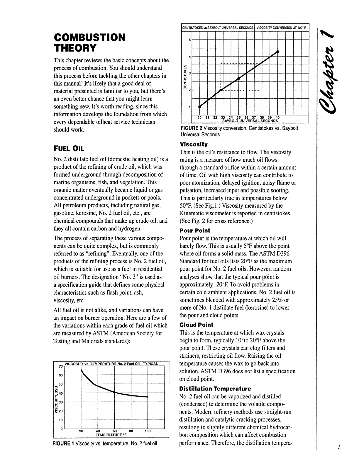
FIGURE 1 Viscosity vs. temperature, No. 2 fuel oil
CENT1STOKESvs.SAYSOLTUNWERSAL SECONDS VISCOSITy"CONVERSION ATi 00' F
5
iUJ _
02 _,. ............ ,
,/
1
3o 3"I _2 3'334 3s 36 37 _ 39 40
SAYBOLT UNIVERSAL SECONDS
FIGURE 2 \_scosity conversion,Centistokesvs.Saybolt
UniversalSeconds
This is the oil's resistance to flow. The viscosity
rating is a measure of how much oil flows
through a standard orifice within a certain amount
of time. Oil with high viscosity can contribute to
poor atomization, delayed ignition, noisy flame or
pulsation, increased input and possible sooting.
This is particularly true in temperatures below
50°E (See Fig, 1,) Viscosity measured by the
Kinematic viscometer is reported in centistokes.
(See Fig. 2 for cross reference.)
Pour Point
Pourpoint is the temperature at which oil will
barely flow. This is usually 5°F above the point
where oil forms a solid mass. The ASTM D396
Standard for fuel oils lists 20°F as the maximum
pour point for No. 2 fuel oils. However, random
analyses show that the typical pour point is
approximately -20°E To avoid problems in
certain cold ambient applications, No. 2 fuel oil is
sometimes blended with approximately 25% or
more of No. 1 distillate fuel (kerosine) to lower
the pour and cloud points.
Cloud Point
This is the temperature at which wax crystals
begin to form, typically 10°to 20°F above the
pour point. These crystals can clog filters and
strainers, restricting oil flow. Raising the oil
temperature causes the wax to go back into
solution. ASTM D396 does not list a specification
on cloud point.
Distillation Temperature
No. 2 fuel oil can be vaporized and distilled
(condensed) to determine the volatile compo-
nents. Modern refinery methods use straight-run
distillation and catalytic cracking processes,
resulting in slightly different chemical hydrocar-
bon composition which can affect combustion
performance. Therefore, the distillation tempera-
turetestisvaluable.It consistsoffueloilbeing
heatedgraduallyinaflaskuntilitvaporizes,then
iscondensedintoagraduatedcylinder.The
temperatureatwhichcondensationbeginsis
calledtheinitialboilingpoint(IBP).Therising
temperatureisrecordedforeachfractiondistilled.
Itisusuallyreportedin10%incrementsuntilthe
finaldropisrecoveredorendpointisreached.
Theinitialboilingpointcouldcauseignition
problemsif it istoohigh(over400°F).The
ignitionarcmustprovideenoughheatenergyto
elevatethetemperatureoftheatomizedoil
dropletstotheinitialboilingpoint.If theIBPis
low,theignitionshouldbeimmediate.Forthe
flametobesustained,the10%pointortempera-
tureatwhich10%ofthetotalvolumeisdistilled
mustberelativelyclose.If thespreadistoolarge,
thentheflamecouldpulsateorevenbeextin-
guished.
Foranestablishedflame,theremainingfractions
of20-80%shouldnotpresentanycombustion
problems,butthe90%andtheendpointcould.
The90%pointisthetemperaturewhere90%of
theoilisdistilled.ASTMD396requiresthistobe
between540°Fminimumand640°E
Awidespreadbetweenthe90%andendpoint
cancausepoorcombustion,sootaridcarbon
depositsontheheatexchangerbecausethe
remainingheavyendsmaynotburncompletely.
Detecting "Out of Spec" Oil
Your first clue that oil is not within ASTM specs
might be a sudden rash of problems: delayed
ignition, smoky fires, appliance sooting and
noisy, dirty flames. If an analysis by a competent
laboratory shows the oil is out of spec, the
supplier should be advised. However, if it is
within spec, but is near the maximum level for
viscosity, pour point or has an IBP above 400°E
chemical additives or blending with about 25%
kerosine might be considered to make the oil
more compatible with cold temperatures, and to
improve its ignition and combustion qualities.
COMBUSTION
When fuel oil is burned, the chemical energy that
is stored in the oil is released in another form of
energy: heat. But to create this conversion of
energy, an external source of heat must be applied
to the oil droplets to start the reaction. The
electric spark delivered by the electrodes of an oil
burner provides the initial heat. The heat from the
electrodes causes oil droplets to become oil vapor
and eventually burn continuously. This burning
then heats the surrounding oil droplets causing
them to bum. This process continues until all or
most of the droplets are vaporizing and burning.
If the conditions for combustion are ideal, all oil
droplets will burn completely and cleanly within
the combustion zone.
Combustion is the process of burning, p
Combustion, as we normally think of it, is
generally described as "rapid oxidation" of any
material which is classified as combustible
matter. The term "oxidation" simply means the
adding of oxygen in a chemical reaction, and
"combustible matter" means any substance which
combines readily and rapidly with oxygen under
certain favorable conditions. Since fuel oil
primarily consists of carbon (85%) and hydrogen
(15%), combustion of fuel oil, according to our
previous definition, is the rapid combining of
carbon and hydrogen with oxygen.
As you know, the oxygen needed for combustion
comes from the air provided by the burner
blower. Approximately 21% of the air is oxygen.
The other 79% is nitrogen. Therefore, to supply
the oxygen needed for combustion, a great deal of
nitrogen goes along for a free fide. This will
become an important factor in later discussions of
proper oil burner adjustment!
What we see and feel from combustion--flames,
smoke, heat--is a result of chemical reactions.
Since we can't see carbon, hydrogen or oxygen
atoms (smallest units to combine), we symbolize
the reactions with formulas that describe the
process. For example:
Carbon +Air oxygen + ] f_
nitrogen J
carbon dioxide + nitrogen + heat (1)
Hydrogen +Air [ oxygen +
nitrogen ]
I.
water vapor + nitrogen + heat (2)
I
I
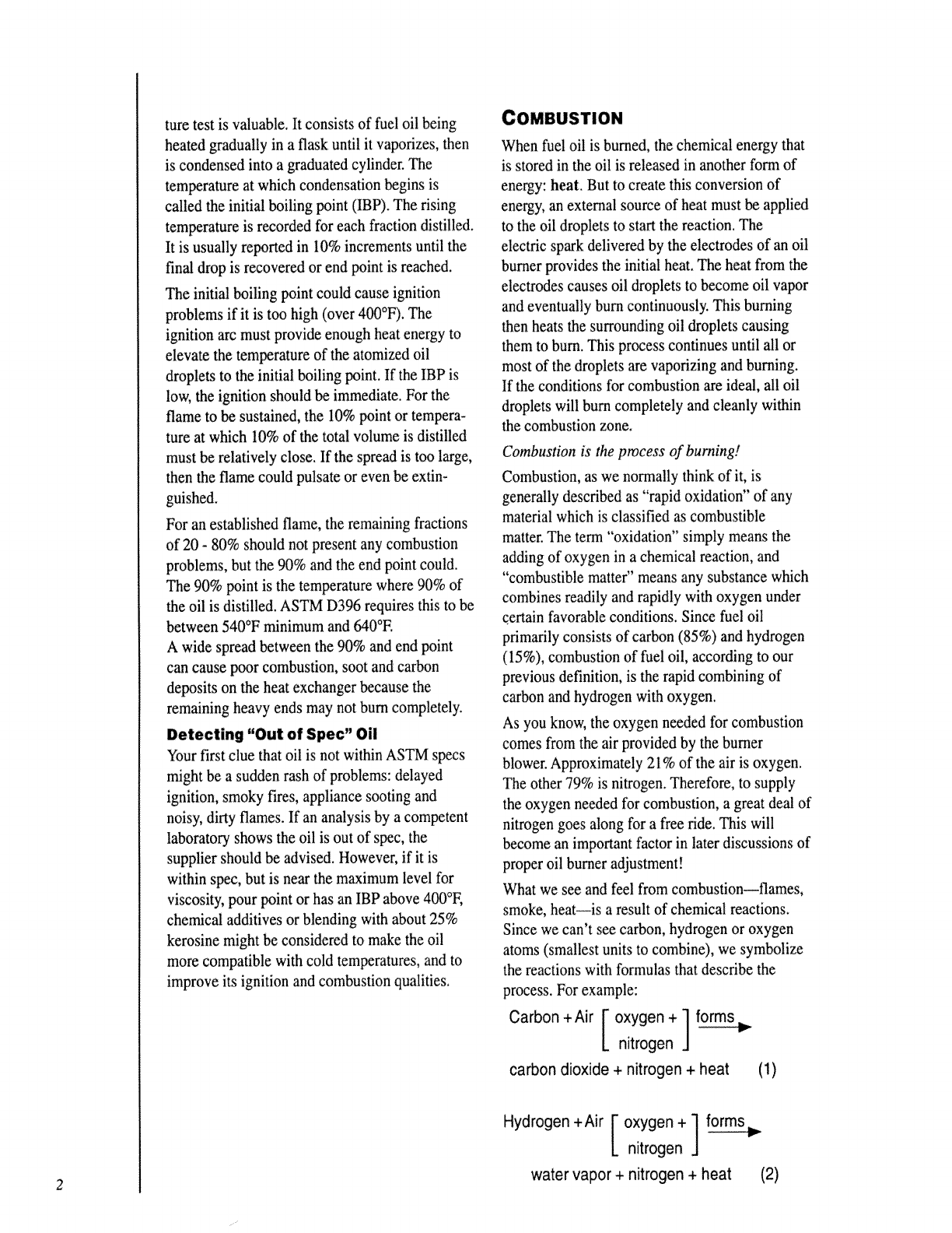
These reactions can be rewritten using symbols in
the following manner:
C+O2+N 2 -_ CO2+N2+heat (1)
2H2+O2+N 2 -_ 2H20+N2+heat (2)
Both chemical reactions produce entirely new
products, and each reaction gives off heat.
However, you may have noticed that in
each reaction nitrogen (N2) has not changed,
OIL
(t pound)
-t-
AIR
(14_36 pounds
or 188 cubic feet)
[Air is 20.9% oxygen
and 79.1% nitrogen]
1.00 lb. oil
14.36 lb. air
15.36 ib. total
I
[
I WATER
(1.18 pounds)
(amount of water vapor is
not considered in % of
CO2 determination
+
FORMS > I
84.7% by volume
NITROGEN
(11.02 pounds or
150 cubic feet)
+
15.3% by volume
CARBON DIOXIDE
(3.16 pounds or
27.2 cubic feet)
1.18 lb. water
11.02 lb. nitrogen
3,16 lb. carbon dioxide
15.36 lb. total
FIGURE 3Amount by weightand volumeof
combustion products when 1 lb. of fuel oil is burned
(0% excess air)
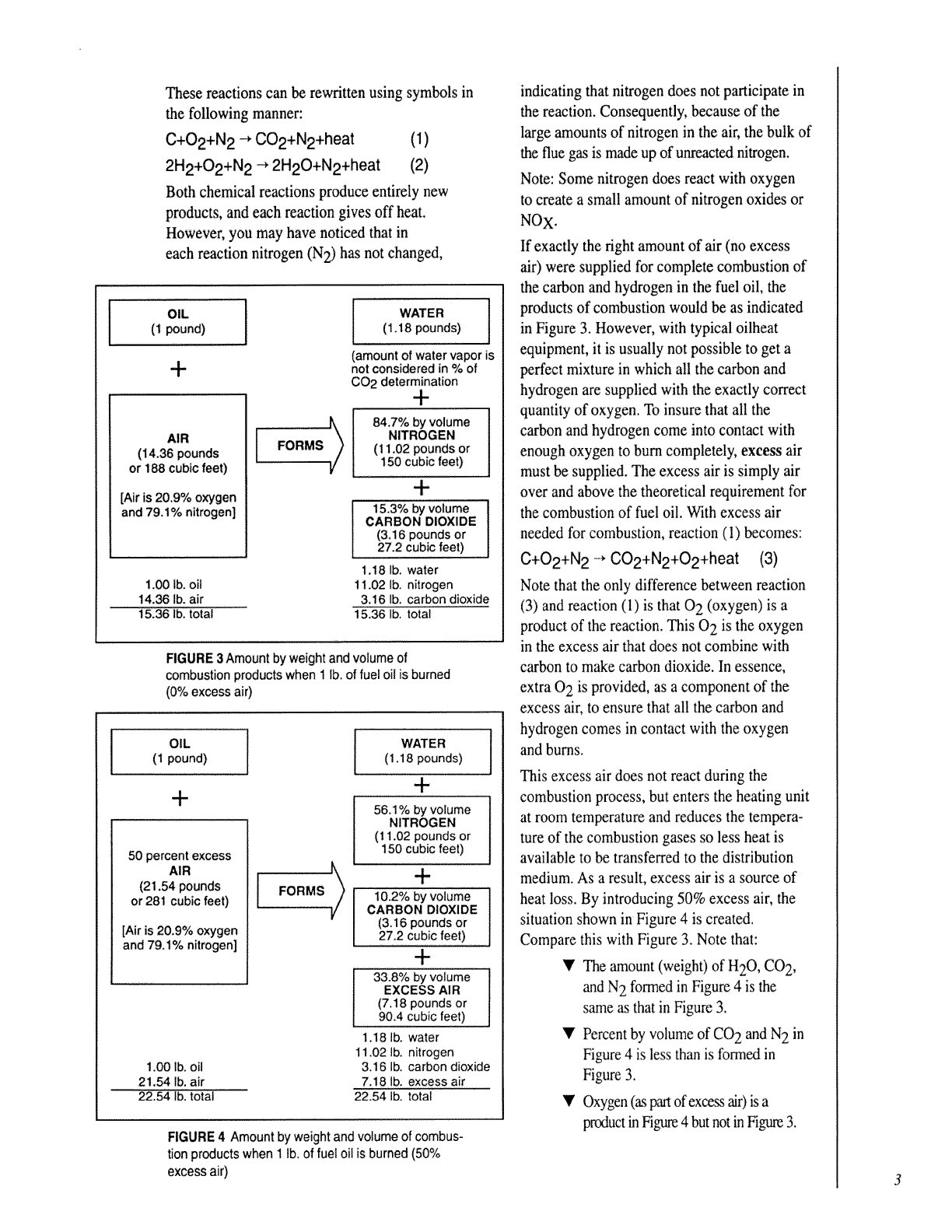
OIL
(1 pound)
-I-
50 pementexcess
AIR
(21.54 pounds
or281 cubicfeet)
[Airis 20,9%oxygen
and 79.1%nitrogen]
1,00 lb. oil
21.54 lb. air
22.54 lb. total
1
FORMS _)
WATER ](1.18 pounds)
+
56.1% by volume
NITROGEN
(11.02 pounds or
150 cubic feet)
+
10.2% byvolume ]
CARBON DIOXIDE l
(3.16 pounds or
27.2 cubic feet)
+
33.8% by volume i
EXCESS AIR !
(7.18 pounds or
90.4 cubic feet)
1.18 lb. water
11.02 lb. nitrogen
3.16 lb. carbon dioxide
7.18 lb. excess air
22.54 lb. total
FIGURE 4 Amount by weight and volume ofcombus-
tion products when 1 lb. of fuel oil is burned (50%
excess air)
indicating that nitrogen does not participate in
the reaction. Consequently, because of the
large amounts of nitrogen in the air, the bulk of
the flue gas is made up of unreacted nitrogen.
Note: Some nitrogen does react with oxygen
to create a small amount of nitrogen oxides or
NOx.
If exactly the right amount of air (no excess
air) were supplied for complete combustion of
the carbon and hydrogen in the fuel oil, the
products of combustion would be as indicated
in Figure 3. However, with typical oilheat
equipment, it is usually not possible to get a
perfect mixture in which all the carbon and
hydrogen are supplied with the exactly correct
quantity of oxygen. To insure that all the
carbon and hydrogen come into contact with
enough oxygen to burn completely, excess air
must be supplied, The excess air is simply air
over and above the theoretical requirement for
the combustion of fuel oil. With excess air
needed for combustion, reaction (1) becomes:
C+02+N 2 -* C02+N2+O2+heat (3)
Note that the only difference between reaction
(3) and reaction (1) is that 0 2 (oxygen) is a
product of the reaction. This 0 2 is the oxygen
in the excess air that does not combine with
carbon to make carbon dioxide. In essence,
extra 0 2 is provided, as a component of the
excess air, to ensure that all the carbon and
hydrogen comes in contact with the oxygen
and bums.
This excess air does not react during the
combustion process, but enters the heating unit
at room temperature and reduces the tempera-
ture of the combustion gases so less heat is
available to be transferred to the distribution
medium. As a result, excess air is a source of
heat loss. By introducing 50% excess air, the
situation shown in Figure 4 is created.
Compare this with Figure 3. Note that:
Y The amount (weight) of H20, CO2,
and N2 formed in Figure 4 is the
same as that in Figure 3.
•'Percent by volume of CO2 and N2 in
Figure 4 is less than is formed in
Figure 3.
_' Oxygen (_ partof excess air) is a
pr_._ductin Figure4 but not in Egtue 3.
4
03
<
O
ILl
-J
It.
z
O
O
Z
LI.I
0
II
LU
I3u
24
22
20
18
16
14
12
10
8
6
4
2
0
!!II!!
MEASURE PERCENT CO 2TO D_ERMINE _
PERCENT EXCESS AIR
_" _IIii _._,m_mi " .iii--
l
0 i0 20 3o 4o so eo 7o 8o 90 i30 i40 1;50
PERCENT EXCESS AIR
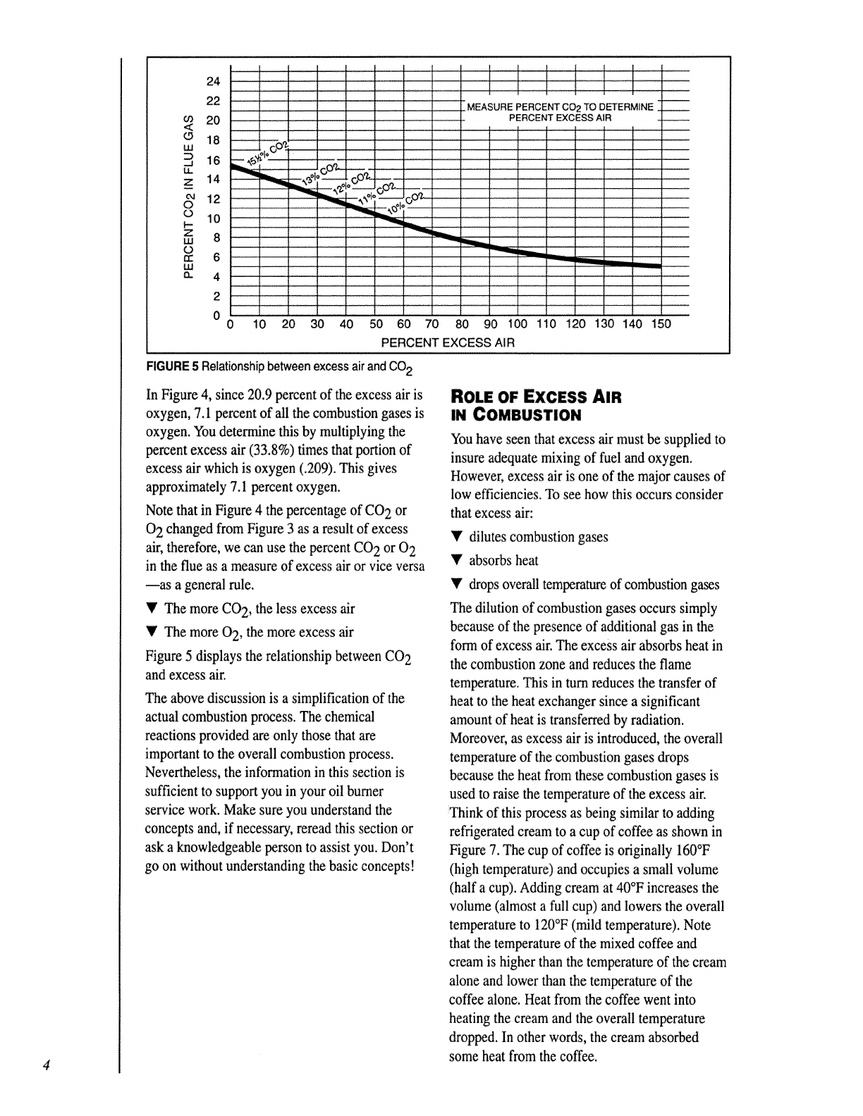
FIGURE 5 Relationship between excess air and CO2
In Figure 4, since 20.9 percent of the excess air is
oxygen, 7.1 percent of all the combustion gases is
oxygen. You determine this by multiplying the
percent excess air (33.8%) times that portion of
excess air which is oxygen (.209). This gives
approximately 7.1 percent oxygen.
Note that in Figure 4 the percentage of CO 2 or
0 2 changed from Figure 3 as a result of excess
air, therefore, we can use the percent CO 2 or 0 2
in the flue as a measure of excess air or vice versa
las a general rule.
'_' The more CO 2, the less excess air
•'The more 0 2, the more excess air
Figure 5 displays the relationship between CO 2
and excess air.
The above discussion is a simplification of the
actual combustion process. The chemical
reactions provided are only those that are
important to the overall combustion process.
Nevertheless, the information in this section is
sufficient to support you in your oil burner
service work. Make sure you understand the
concepts and, if necessary, reread this section or
ask a knowledgeable person to assist you. Don't
go on without understanding the basic concepts!
ROLE OF EXCESS AIR
IN COMBUSTION
You have seen that excess air must be supplied to
insure adequate mixing of fuel and oxygen.
However, excess air is one of the major causes of
low efficiencies. To see how this occurs consider
that excess air:
Ydilutes combustion gases
Yabsorbs heat
•'drops overall temperature of combustion gases
The dilution of combustion gases occurs simply
because of the presence of additional gas in the
form of excess air. The excess air absorbs heat in
the combustion zone and reduces the flame
temperature. This in turn reduces the transfer of
heat to the heat exchanger since a significant
amount of heat is transferred by radiation.
Moreover, as excess air is introduced, the overall
temperature of the combustion gases drops
because the heat from these combustion gases is
used to raise the temperature of the excess air.
Think of this process as being similar to adding
refrigerated cream to a cup of coffee as shown in
Figure 7. The cup of coffee is originally 160°F
(high temperature) and occupies a small volume
(half a cup). Adding cream at 40°F increases the
volume (almost a full cup) and lowers the overall
temperature to 120°F (mild temperature). Note
that the temperature of the mixed coffee and
cream is higher than the temperature of the cream
alone and lower than the temperature of the
coffee alone. Heat from the coffee went into
heating the cream and the overall temperature
dropped. In other words, the cream absorbed
some heat from the coffee.
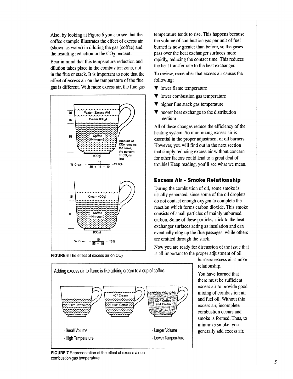
Also,bylookingatFigure6youcanseethatthe
coffeeexampleillustratestheeffectofexcessair
(shownaswater)indilutingthegas(coffee)and
theresultingreductionintheCO2percent.
Bearinmindthatthistemperaturereductionand
dilutiontakesplaceinthecombustionzone,not
intheflueorstack.Itisimportanttonotethatthe
effectofexcessaironthetemperatureoftheflue
gasisdifferent.Withmoreexcessair,thefluegas
10
15
85
Water (Excess Air)
Cream 1CO21
_._ coffee
(C02)
15
% Cream =13.6%
85+15+10
Amount of
CO2 remains
the same,
the percent
of CO2is
less
15
85
Cream (CO 2)
.,,...,_ ( N t oge | _,,_,,...,,._
(C02)
15
% Cream 15%
85+15
FIGURE 6 The effectof excess air on CO2
Addingexcessairtoflameislikeaddingcreamtoacup ofcoffee.
temperature tends to rise. This happens because
the volume of combustion gas per unit of fuel
burned is now greater than before, so the gases
pass over the heat exchanger surfaces more
rapidly, reducing the contact time. This reduces
the heat transfer rate to the heat exchanger.
To review, remember that excess air causes the
following:
•'lower flame temperature
Y lower combustion gas temperature
T higher flue stack gas temperature
T poorer heat exchange to the distribution
medium
.SmallVolume
•HighTemperature
All of these changes reduce the efficiency of the
heating system• So minimizing excess air is
essential in the proper adjustment of oil burners.
However, you will find out in the next section
that simply reducing excess air without concern
for other factors could lead to a great deal of
trouble! Keep reading, you'll see what we mean.
. LargerVolume
•LowerTemperature
Excess Air. Smoke Relationship
During the combustion of oil, some smoke is
usually generated, since some of the oil droplets
do not contact enough oxygen to complete the
reaction which forms carbon dioxide. This smoke
consists of small particles of mainly unburned
carbon. Some of these particles stick to the heat
exchanger surfaces acting as insulation and can
eventually clog up the flue passages, while others
are emitted through the stack.
Now you are ready for discussion of the issue that
is all important to the proper adjustment of oil
burners: excess air-smoke
relationship.
You have learned that
there must be sufficient
excess air to provide good
mixing of combustion air
and fuel oil. Wqthout this
excess air, incomplete
combustion occurs and
smoke is formed. Thus, to
minimize smoke, you
generally add excess air.
FIGURE 7 Representation of theeffect of excess air on
combustion gas temperature
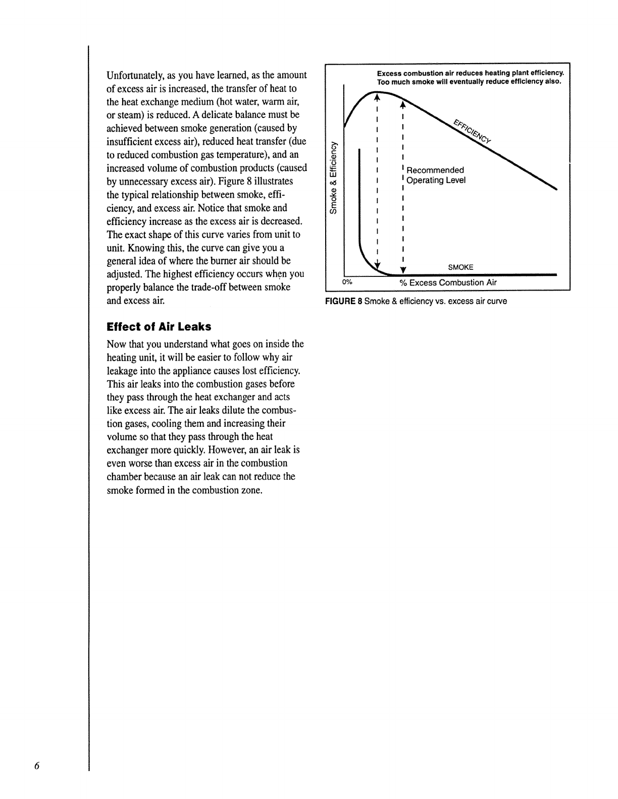
Unfortunately, as you have learned, as the amount
of excess air is increased, the transfer of heat to
the heat exchange medium (hot water, warm air,
or steam) is reduced. A delicate balance must be
achieved between smoke generation (caused by
insufficient excess air), reduced heat transfer (due
to reduced combustion gas temperature), and an
increased volume of combustion products (caused
by unnecessary excess air). Figure 8 illustrates
the typical relationship between smoke, effi-
ciency, and excess air. Notice that smoke and
efficiency increase as the excess air is decreased.
The exact shape of this curve varies from unit to
unit. Knowing this, the curve can give you a
general idea of where the burner air should be
adjusted. The highest efficiency occurs when you
properly balance the trade-off between smoke
and excess air.
Effect of Air Leaks
Now that you understand what goes on inside the
heating unit, it will be easier to follow why air
leakage into the appliance causes lost efficiency.
This air leaks into the combustion gases before
they pass through the heat exchanger and acts
like excess air. The air leaks dilute the combus-
tion gases, cooling them and increasing their
volume so that they pass through the heat
exchanger more quickly, However, an air leak is
even worse than excess air in the combustion
chamber because an air leak can not reduce the
smoke formed in the combustion zone.
Excess combustion air reduces heating plant efficiency.
Too much smoke will eventually reduce efficiency also.
g-
Recommended
LLI
<1 Operating Level
o
E
o')
k'_L SMOKE
i i
o% % Excess Combustion Air
FIGURE 8 Smoke & efficiency vs. excess air curve
6
OILHEAT SYSTEMS
OVERVIEW OF OILHEAT SYSTEMS
The primapy emphasis of this manual is on oil
burners. However, a brief look at total oilheat
systems would be appropriate. Maximum heating
efficiency, reliability, and safety cannot be
achieved unless all components of the system are
compatible and in top working condition. It is
vital, therefore, that the technician consider the
entire system when installing new equipment or
servicing existing equipment.
The purpose of any oilheat system is to convert
fuel oil into heat, and distribute as much of that
heat as possible to the home.
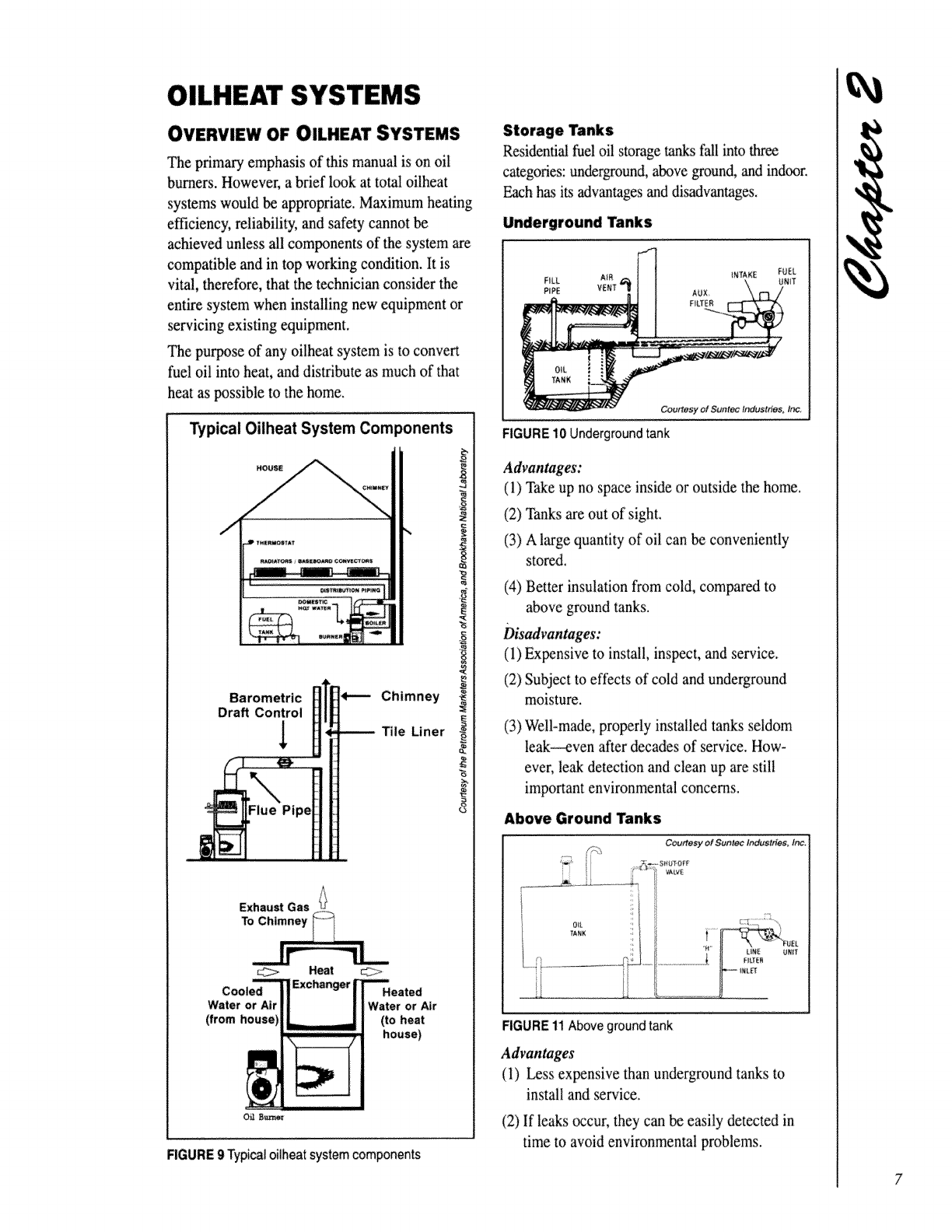
Typical Oilheat System Components
HOU_
Barometric _Chimney
Draft Control
_, Tile Liner
_Heat __;>
Cooled Exchan_ Heated
Water or Air Water or Air
(from house (to heat
house)
RGURE 9 _pi_l oilheatsystem components
Storage Tanks
Residential fuel oil storage tan_ksfall into three
categories: underground, above ground, and indoor.
Each has i_ advantages and disadvantages.
Underground Tanks
Courtesy of Suntec tr_ustdes, In_
FIGURE10Undergroundtank
Advantages:
(1) Take up no space inside or outside the home.
(2) Tanks are out of sight,
(3) A large quantity of oil can be conveniently
stored.
(4) Better insulation from cold, compared to
above ground tanks.
Disadvantages:
(1) ExNnsive to install, inspect, and service.
(2) Subject to effects of cold and underground
moisture.
(3) Well-made, properly installed tanks seldom
leak_ven after decades of service. How-
ever, leak detection and clean up are still
important environmental concerns.
Above Ground Tanks
Courtesy of Suntec Industries, Inc.
UNIT
FIGURE 11 Above ground tank
Advantages
(I) less expensive than underground tanks to
install and service.
(2) If leaks occur, they can be easily detected in
time to avoid environmental problems.
8
Disadvantages:
(1) Exposed to cold and moisture. (These
problems can be reduced by providing a
shelter for the _k.)
(2) Take up outdoor space.
(3) May detract from appearance of home.
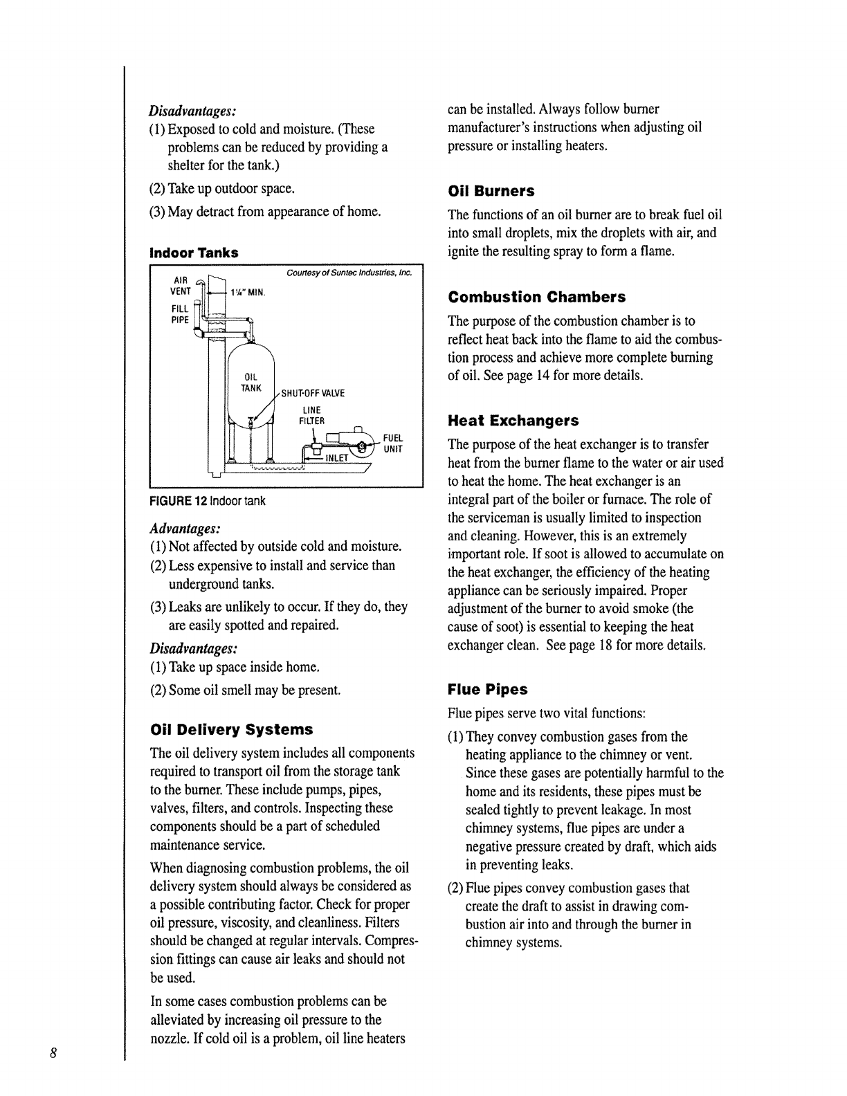
Indoor Tanks
VENTll_
Courtesy of Suntec Industries, Inc.
• 1%" MIN.
_LK_ SHUT-OFFVALVE
LINE
FIGURE 12 Indoor tank
Advantages:
(1) Not affected by outside cold and moisture.
(2) Less expensive to install and service than
underground tanks.
(3) Leaks are unlikely to occur. If they do, they
are easily spotted and repaired.
Disadvantages:
(1) Take up space inside home.
(2) Some oil smell may be present.
Oil Delivery Systems
The oil delivery system includes all components
required to transport oil from the storage tank
to the burner. These include pumps, pipes,
valves, filters, and controls. Inspecting these
components should be a part of scheduled
maintenance service.
When diagnosing combustion problems, the oil
delivery system should always be considered as
a possible contributing factor. Check for proper
oil pressure, viscosity, and cleanliness. Filters
should be changed at regular intervals. Compres-
sion fittings can cause air leaks and should not
be used.
In some cases combustion problems can be
alleviated by increasing oil pressure to the
nozzle. If cold oil is a problem, oil line heaters
can be installed. Always follow burner
manufacturer's instvactions when adjusting oil
pressure or installing heaters.
Oil Burners
The functions of an oil burner are to break fuel oil
into small droplets, mix the droplets with air, and
ignite the resulting spray to form a flame.
Combustion Chambers
The purpose of the combustion chamber is to
reflect heat back into the flame to aid the combus-
tion process and achieve more complete burning
of oil. See page 14 for more details.
Heat Exchangers
The purpose of the heat exchanger is to transfer
heat from the burner flame to the water or air used
to heat the home. The heat exchanger is an
integral part of the boiler or furnace. The role of
the serviceman is usually limited to inspection
and cleaning. However, this is an extremely
important role. If soot is allowed to accumulate on
the heat exchanger, the efficiency of the heating
appliance can be seriously impaired. Proper
adjustment of the burner to avoid smoke (the
cause of soot) is essential to keeping the heat
exchanger clean. See page 18 for more details.
Flue Pipes
Flue pipes serve two vital functions:
(1) They convey combustion gases from the
heating appliance to the chimney or vent.
Since these gases are potentially harmful to the
home and its residents, these pipes must be
sealed tightly to prevent leakage. In most
chimney systems, flue pipes are under a
negative pressure created by draft, which aids
in preventing leaks.
(2) Flue pipes convey combustion gases that
create the draft to assist in drawing com-
bustion air into and through the burner in
chimney systems.
Draft Regulators
Many flue pipes include a barometric draft
regulator. This consists of a counterweighted
swinging door which opens and closes to help
maintain a constant level of draft over the fire.
Modern high-speed, flame retention burners are
much less sensitive to changes in natural draft
allowing draft regulators to be eliminated in some
cases. However, check the burner manufacturer's
instructions, and local codes, before eliminating
draft regulators. See page 22 for more details.
Chimneys
Chimneys have been used since the earliest days
of indoor heating to draw combustion gases out of
the home and provide draft to help draw in
combustion air. Correct chimney design and
careful maintenance are essential to the operation
of any oilheat system.
When chimneys are inadequate or absent entirely
(such as in electric-to-oil conversions), alternative
venting systems are available. See page 25 for
more details.
Heat Distribution Systems
With furnaces, warm air, propelled by fans, is
distributed throughout the house through metal
ducts. With boilers, hot water or steam is distrib-
uted through pipes. These heat distribution
systems can be important sources of heat loss.
Check air ducts for leaks, and consider insulation
for water and steam pipes.
Controls
The controls used to regulate typical oilheat
systems include the following:
(1) The Thermostat "tells" the burner when to
turn on and off to maintain the desired
temperature in the house. Programmable
thermostats automatically lower and raise
temperature settings at timed intervals
throughout the day and night, to conform to
the changing ne_edsof the home occupants.
This can produce significant fuel savings.
(2) TheAquastat regulates the temperature of
boiler water.
(3) The Fan Control turns the fan on and off in
warm air furnace systems.
(4) Pump and Zone "/hive Controls regulate the
flow of water or steam in boiler systems.
(5) Safety Controls such as pressure relief
valves, high temperature limits, low water cut
offs, and burner primary controls protect
against appliance malfunctions.
When adjusting controls, follow manufacturer's
instructions.
The House
The house itself has a major effect on the
performance of the heating system, especially on
the combustion air supply. Newer, tightly sealed
houses have different requirements than older
houses with greater air infiltration. Exhaust fans,
vented clothes dryers, and ventilating systems
also have an effect on available air for combus-
tion. It is essential that the technician consider
these factors when recommending a heating
system, or diagnosing system problems.
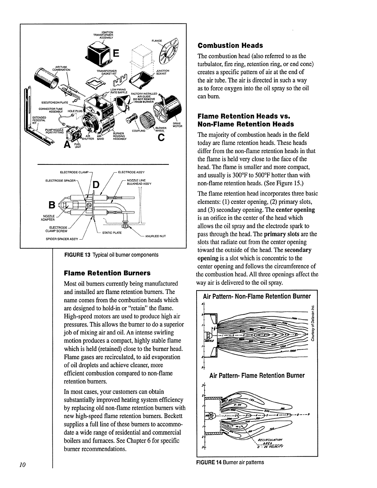
BASIC OIL BURNER DESIGN
Most oil burners in use today operate as follows:
(See Figure 13.)
(1) Oil is delivered under pressure (usually about
100 psig--although some models require
pressures in the 140-200 psig range) by the oil
pump (A) to the nozzle (B). Check
manufacturer's specifications for proper pump
pressure settings.
(2) The nozzle breaks up the oil into a spray of
tiny droplets from .0002 to .0100 inches in
diameter which evaporate rapidly into a
vapor.
(3) The vapor is mixed at the burner head with a
stream of air from the blower wheel (C).
(4) The oil vapor combines with oxygen from the
air stream and is ignited (initially) by an
electric arc from the electrodes (D), powered
by a high voltage transformer (E), to produce
a flame.
(5) Heat is reflected back into the flame by the
combustion chamber, to help evaporate the oil
droplets. This helps achieve more complete
burning of the oil.
(6) This combustion process continues until the
burner is shut down for the off cycle.
(7) The entire process begins again with the next
on cycle. 9
c
NOZZLE
ELE
CLAMP SCREW _ STA_dC PLATE _\
SPtDER SPACER ASS'Y J _- KNURLED NUT
FIGURE 13 Typicaloilburner components
Flame Retention Burners
Most oil burners currently being manufactured
and installed are flame retention burners. The
name comes from the combustion heads which
are designed to hold-in or "retain" the flame.
High-speed motors are used to produce high air
pressures. This allows the burner to do a superior
job of mixing air and oil. An intense swirling
motion produces a compact, highly stable flame
which is held (retained) close to the burner head.
Flame gases are recirculated, to aid evaporation
of oil droplets and achieve cleaner, more
efficient combustion compared to non-flame
retention burners.
In most cases, your customers can obtain
substantially improved heating system efficiency
by replacing old non-flame retention burners with
new high-speed flame retention burners. Beckett
supplies a full line of these burners to accommo-
date a wide range of residential and conur_ercial
boilers and furnaces. See Chapter 6 for specific
burner recommendations.
Combustion Heads
The combustion head (also referred to as the
turbulator, fire ring, retention ring, or end cone)
creates a specific pattern of air at the end of
the air tube. The air is directed in such a way
as to force oxygen into the oil spray so the oil
can burn.
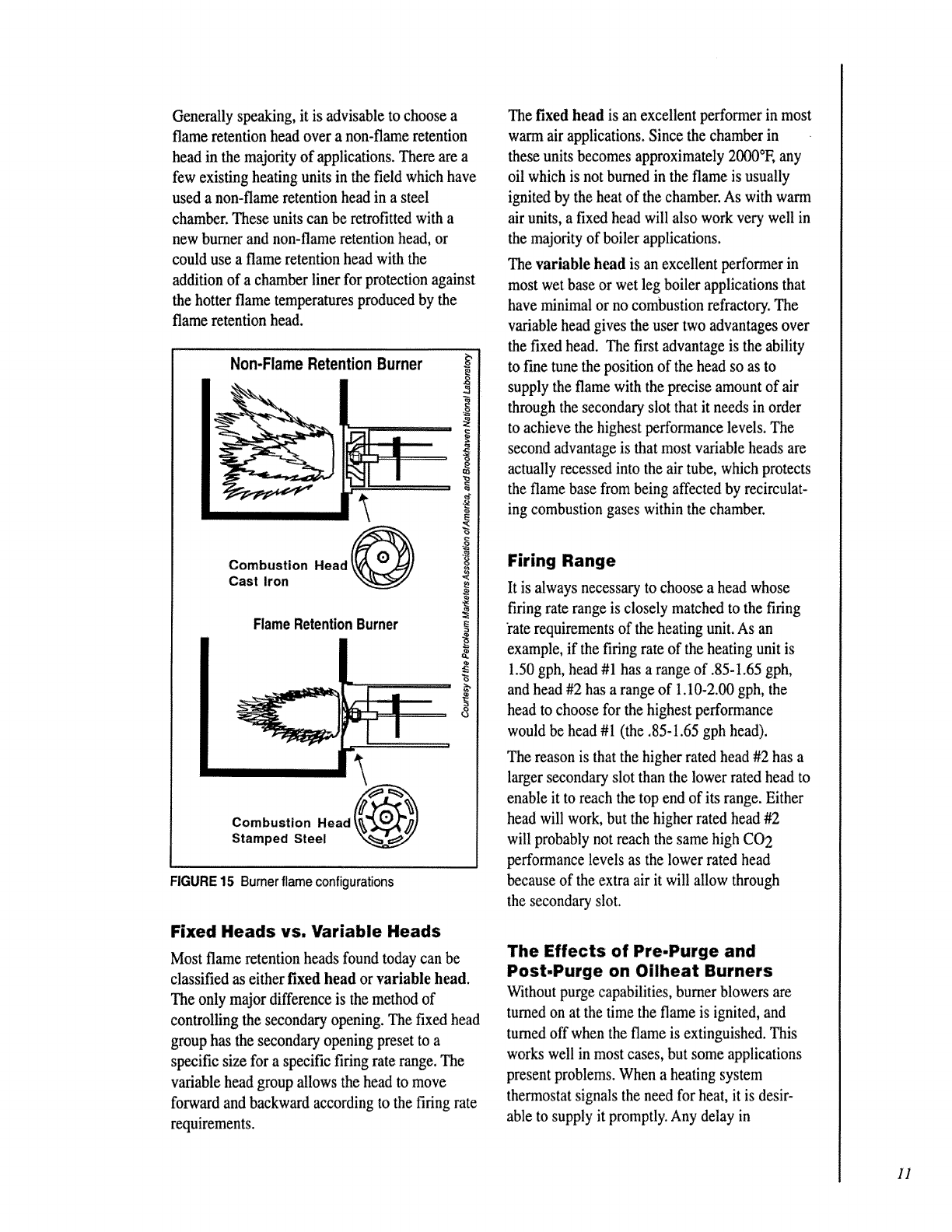
Flame Retention Heads vs.
Non-Flame Retention Heads
The majority of combustion heads in the field
today are flame retention heads. These heads
differ from the non-flame retention heads in that
the flame is held very close to the face of the
head. The flame is smaller and more compact,
and usually is 300°F to 500°F hotter than with
non-flame retention heads. (See Figure 15.)
The flame retention head incorporates three basic
elements: (1) center opening, (2) primary slots,
and (3) secondary opening. The center opening
is an orifice in the center of the head which
allows the oil spray and the electrode spark to
pass through the head. The primary slots are the
slots that radiate out from the center opening
toward the outside of the head. The secondary
opening is a slot which is concentric to the
center opening and follows the circumference of
the combustion head. All three openings affect the
way air is delivered to the oil spray.
Air Pattern- Non-Flame Retention Burner
_3
"6
Air Pattern-FlameRetentionBurner
10 FIGURE14Burnerair patterns
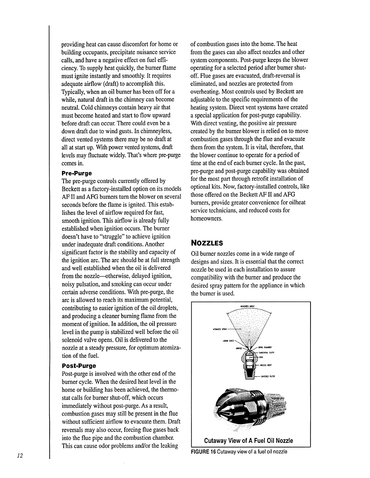
Generally speaking, it is advisable to choose a
flame retention head over a non-flame retention
head in the majority of applications. There are a
few existing heating units in the field which have
used a non-flame retention head in a steel
chamber. These units can be retrofitted with a
new burner and non-flame retention head, or
could use a flame retention head with the
addition of a chamber liner for protection against
the hotter flame temperatures produced by the
flame retention head.
Non-Flame Retention Burner
Combustion Head 0
Cast Iron
FlameRetentionBurner
FIGURE 15 Burner flame configurations
Fixed Heads vs. Variable Heads
Most flame retention heads found today can be
classified as either fixed head or variable head.
The only major difference is the method of
controlling the secondary opening. The fixed head
group has the secondary opening preset to a
specific size for a specific firing rate range. The
variable head group allows the head to move
forward and backward according to the firing rate
requirements.
The fixed head is an excellent performer in most
warm air applications. Since the chamber in
these units becomes approximately 2000°E any
oil which is not burned in the flame is usually
ignited by the heat of the chamber. As with warm
air units, a fixed head will also work very well in
the majority of boiler applications.
The variable head is an excellent performer in
most wet base or wet leg boiler applications that
have minimal or no combustion refractory. The
variable head gives the user two advantages over
the fixed head. The first advantage is the ability
to fine tune the position of the head so as to
supply the flame with the precise amount of air
through the secondary slot that it needs in order
to achieve the highest performance levels. The
second advantage is that most variable heads are
actually recessed into the air tube, which protects
the flame base from being affected by recirculat-
ing combustion gases within the chamber.
Firing Range
It is always necessary to choose a head ',,chose
firing rate range is closely matched to the firing
'rate requirements of the heating unit. As an
example, if the firing rate of the heating unit is
1.50 gph, head #1 has a range of .85-1.65 gph,
and head #2 has a range of 1.10-2.00 gph, the
head to choose for the highest performance
would be head #1 (the .85-1.65 gph head),
The reason is that the higher rated head #2 has a
larger secondary slot than the lower rated head to
enable it to reach the top end of its range. Either
head will work, but the higher rated head #2
will probably not reach the same high CO2
performance levels as the lower rated head
because of the extra air it will allow through
the secondary slot.
The Effects of Pre-Purge and
Post-Purge on Oilheat Burners
Without purge capabilities, burner blowers are
turned on at the time the flame is ignited, and
turned off when the flame is extinguished. This
works well in most cases, but some applications
present problems. When a heating system
thermostat signals the need for heat, it is desir-
able to supply it promptly. Any delay in
11
12
providing heat can cause discomfort for home or
building occupants, precipitate nuisance service
calls, and have a negative effect on fuel effi-
ciency. To supply heat quickly, the burner flame
must ignite instantly and smoothly. It requires
adequate airflow (draft) to accomplish this.
Typically, when an oil burner has been off for a
while, natural draft in the chimney can become
neutral. Cold chimneys contain heavy air that
must become heated and start to flow upward
before draft can occur. There could even be a
down draft due to wind gusts. In chimneyless,
direct vented systems there may be no draft at
all at start up. With power vented systems, draft
levels may fluctuate widely. That's where pre-purge
comes in.
The pre-purge controls currently offered by
Beckett as a factory-installed option on its models
AF II and AFG burners turn the blower on several
seconds before the flame is ignited. This estab-
lishes the level of airflow required for fast,
smooth ignition. This airflow is already fully
established when ignition occurs. The burner
doesn't have to "struggle" to achieve ignition
under inadequate draft conditions. Another
significant factor is the stability and capacity of
the ignition arc. The arc should be at full strength
and well established when the oil is delivered
from the nozzle--otherwise, delayed ignition,
noisy pulsation, and smoking can occur under
certain adverse conditions. With pre-purge, the
arc is allowed to reach its maximum potential,
contributing to easier ignition of the oil droplets,
and producing a cleaner burning flame from the
moment of ignition. In addition, the oil pressure
level in the pump is stabilized well before the oil
solenoid valve opens. Oil is delivered to the
nozzle at a steady pressure, for optimum atomiza-
tion of the fuel.
Post-purge is involved with the other end of the
burner cycle. When the desired heat level in the
home or building has been achieved, the thermo-
stat calls for burner shut-off, which occurs
immediately without post-purge. As a result,
combustion gases may still be present in the flue
without sufficient airflow to evacuate them. Draft
reversals may also occur, forcing flue gases back
into the flue pipe and the combustion chamber.
This can cause odor problems and/or the leaking
of combustion gases into the home. The heat
from the gases can also affect nozzles and other
system components. Post-purge keeps the blower
operating for a selected period after burner shut-
off. Flue gases are evacuated, draft-reversal is
eliminated, and nozzles are protected from
overheating. Most controls used by Beckett are
adjustable to the specific requirements of the
heating system. Direct vent systems have created
a special application for post-purge capability.
With direct venting, the positive air pressure
created by the burner blower is relied on to move
combustion gases through the flue and evacuate
them from the system. It is vital, therefore, that
the blower continue to operate for a period of
time at the end of each burner cycle. In the past,
pre-purge and post-purge capability was obtained
for the most part through retrofit installation of
optional kits. Now, factory-installed controls, like
those offered on the Beckett AF II and AFG
burners, provide greater convenience for oilheat
service technicians, and reduced costs for
homeowners.
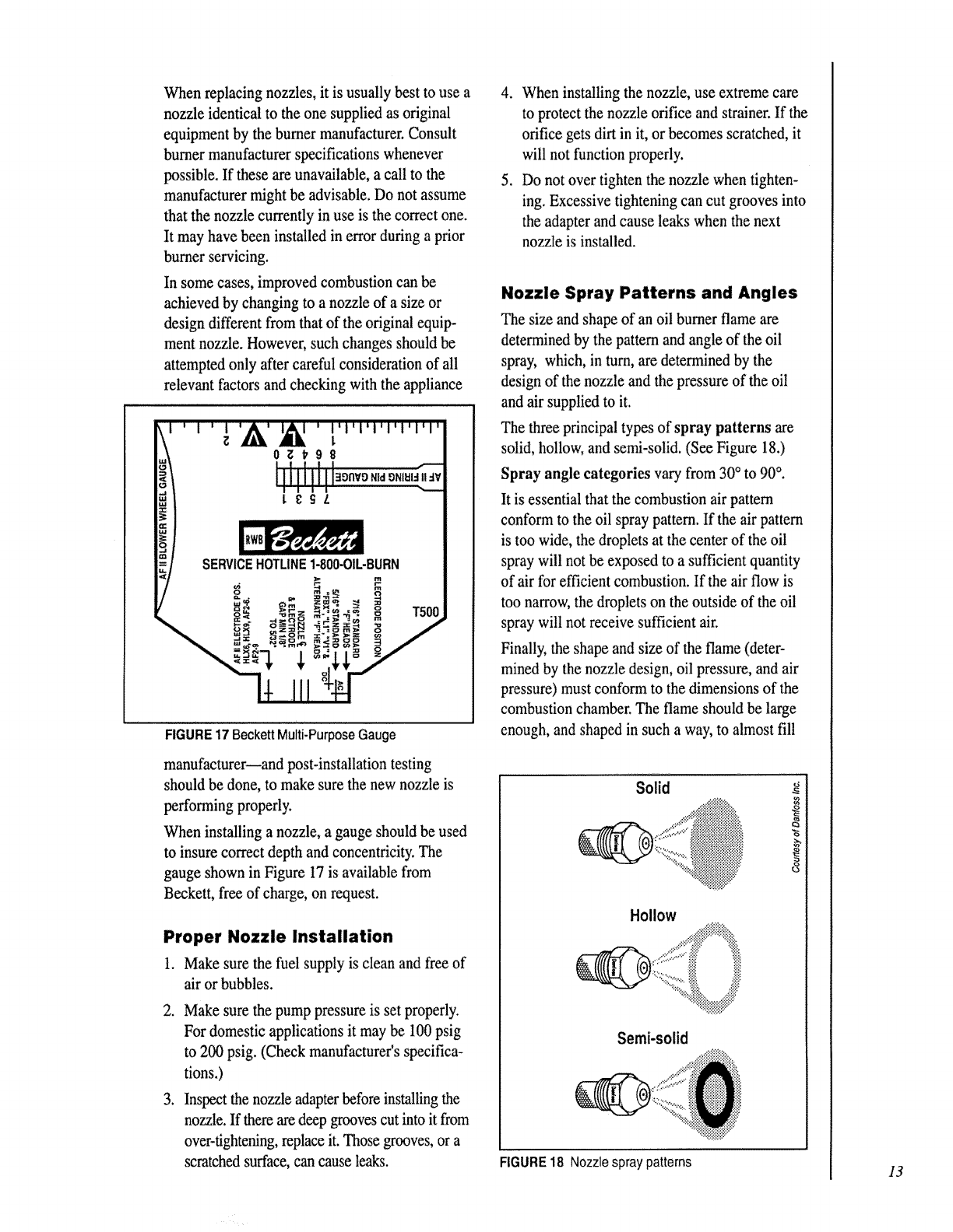
Oil burner nozzles come in a wide range of
designs and sizes. It is essential that the correct
nozzle be used in each installation to assure
compatibility with the burner and produce the
desired spray pattern for the appliance in which
the burner is used.
Cutaway View of A Fuel Oil Nozzle
FIGURE16Cutawayviewofa fueloilnozzle
When replacing nozzles, it is usually best to use a
nozzle identical to the one supplied as original
equipment by the burner manufacturer. Consult
burner manufacturer specifications whenever
possible. If these are unavailable, a call to the
manufacturer might be advisable. Do not assume
that the nozzle currently in use is the correct one.
It may have been installed in error during a prior
burner servicing.
In some cases, improved combustion can be
achieved by changing to a nozzle of a size or
design different from that of the original equip-
ment nozzle. However, such changes should be
attempted only after careful consideration of all
relevant factors and checking with the appliance
SERVICEHOTLINE1-800-OIL,BURN
FIGURE 17 Beckett Multi-Purpose Gauge
manufacturer--and post-installation testing
should be done, to make sure the new nozzle is
performing properly.
When installing a nozzle, a gauge should be used
to insure correct depth and concentricity. The
gauge shown in Figure 17 is available from
Beckett, free of charge, on request.
Proper Nozzle Installation
1. Make sure the fuel supply is clean and free of
air or bubbles.
2. Make sure the pump pressure is set properly.
For domestic applications it may be 100 psig
to 200 psig. (Check manufacturer's specifica-
tions.)
3. Inspect the nozzle adapter before installing the
nozzle. If there are deep grooves cut into it from
over-tightening, replace it. Those grooves, or a
scratched surface, can cause leaks.
4. When installing the nozzle, use extreme care
to protect the nozzle orifice and strainer. If the
orifice gets dirt in it, or becomes scratched, it
will not function properly.
5. Do not over tighten the nozzle when tighten-
ing. Excessive tightening can cut grooves into
the adapter and cause leaks when the next
nozzle is installed.
Nozzle Spray Patterns and Angles
The size and shape of an oil burner flame are
determined by the pattern and angle of the oil
spray, which, in turn, are determined by the
design of the nozzle and the pressure of the oil
and air supplied to it.
The three principal types of spray patterns are
solid, hollow, and semi-solid. (See Figure 18.)
Spray angle categories vary from 30° to 90 °.
It is essential that the combustion air pattern
conform to the oil spray pattern. If the air pattern
is too wide, the droplets at the center of the oil
spray will not be exposed to a sufficient quantity
of air for efficient combustion. If the air flow is
too narrow, the droplets on the outside of the oil
spray will not receive sufficient air.
Finally, the shape and size of the flame (deter-
mined by the nozzle design, oil pressure, and air
pressure) must conform to the dimensions of the
combustion chamber. The flame should be large
enough, and shaped in such a way, to almost fill
Solid
Q
"6
Semi-solid
FIGURE 18 Nozzle spray patterns 13
14
the combustion chamber without actually
touching any part of the chamber surface.
Be sure to follow specifications provided by
manufacturers.
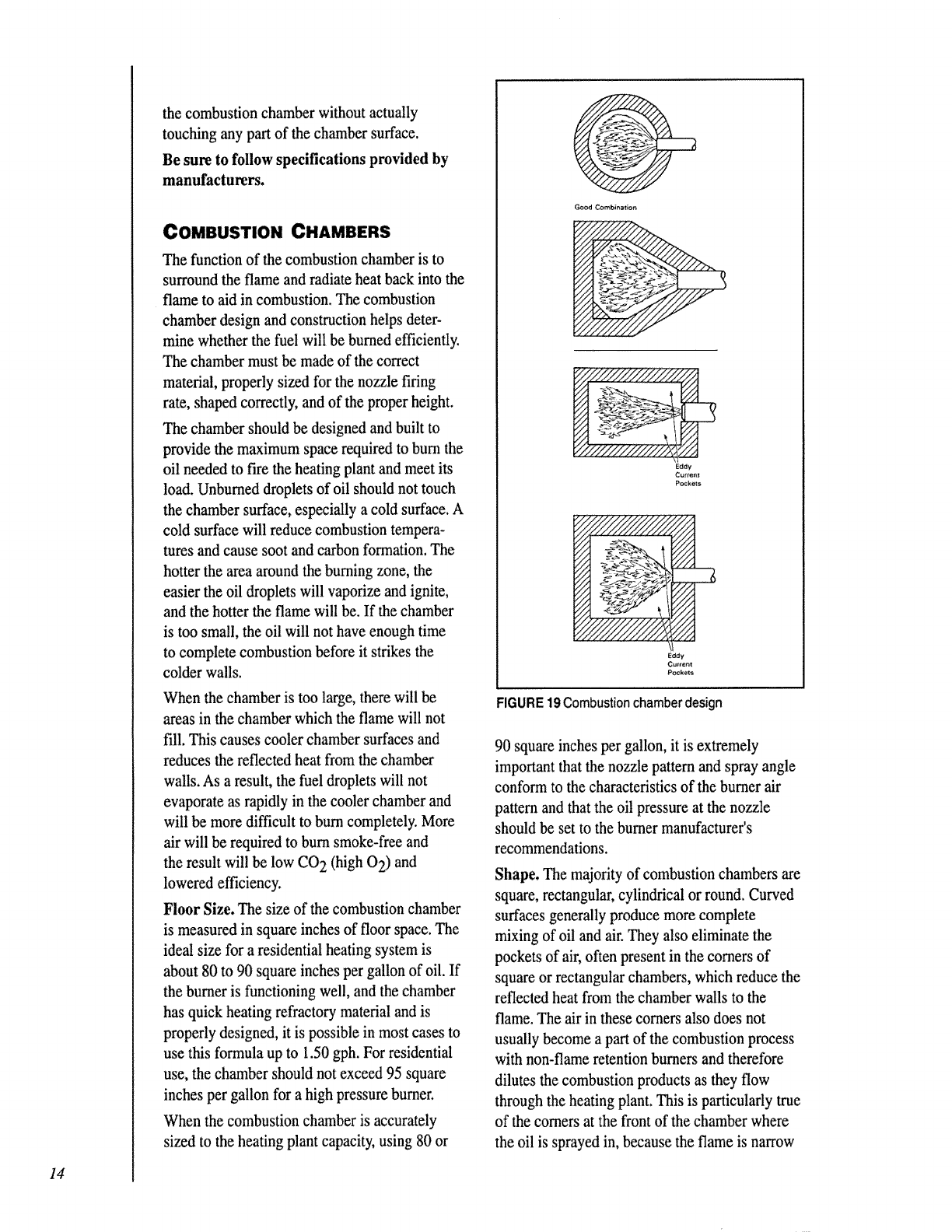
COMBUSTION CHAMBERS
The function of the combustion chamber is to
surround the flame and radiate heat back into the
flame to aid in combustion. The combustion
chamber design and construction helps deter-
mine whether the fuel will be burned efficiently.
The chamber must be made of the correct
material, properly sized for the nozzle firing
rate, shaped correctly, and of the proper height.
The chamber should be designed and built to
provide the maximum space required to burn the
oil needed to fire the heating plant and meet its
load. Unburned droplets of oil should not touch
the chamber surface, especially a cold surface. A
cold surface will reduce combustion tempera-
tures and cause soot and carbon formation. The
hotter the area around the burning zone, the
easier the oil droplets will vaporize and ignite,
and the hotter the flame will be. If the chamber
is too small, the oil will not have enough time
to complete combustion before it strikes the
colder walls.
When the chamber is too large, there will be
areas in the chamber which the flame will not
fill. This causes cooler chamber surfaces and
reduces the reflected heat from the chamber
walls. As a result, the fuel droplets will not
evaporate as rapidly in the cooler chamber and
•,viii be more difficult to burn completely. More
air will be required to burn smoke-free and
the result will be low CO 2 (high 0 2) and
lowered efficiency.
Floor Size. The size of the combustion chamber
is measured in square inches of floor space. The
ideal size for a residential heating system is
about 80 to 90 square inches per gallon of oil. If
the burner is functioning well, and the chamber
has quick heating refractory material and is
properly designed, it is possible in most cases to
use this formula up to 1.50 gph. For residential
use, the chamber should not exceed 95 square
inches per gallon for a high pressure burner.
When the combustion chamber is accurately
sized to the heating plant capacity, using 80 or
Good Combiner;on
N
Eddy
Curten_
Pockets
Eddy
u_ent
Pockels
FIGURE 19Combustion chamber design
90 square inches per gallon, it is extremely
important that the nozzle pattern and spray angle
conform to the characteristics of the burner air
pattern and that the oil pressure at the nozzle
should be set to the burner manufacturer's
recommendations.
Shape. The majority of combustion chambers are
square, rectangular, cylindrical or round. Curved
surfaces generally produce more complete
mixing of oil and air. They also eliminate the
pockets of air, often present in the corners of
square or rectangular chambers, which reduce the
reflected heat from the chamber walls to the
flame. The air in these corners also does not
usually become a part of the combustion process
with non-flame retention burners and therefore
dilutes the combustion products as they flow
through the heating plant. This is particularly true
of the corners at the front of the chamber where
the oil is sprayed in, because the flame is narrow
and the oil has not been heated up to maximum
temperatureat this point. (SeeFigure 19.)
Modern flame retention burners are not as
dependent on chamber shape.
A well designed chamberwill confine the flame,
and more reflected heat will enter the combustion
process in its early stages. Thiswillaidcombus-
tion and provide much smootherignition.In
makingalterationsinthe chamber,you must keep
in mind thatyou must use the nozzlespray pattern
and angle to fit the chamberas recommendedby
manufacturer'sspecifications.
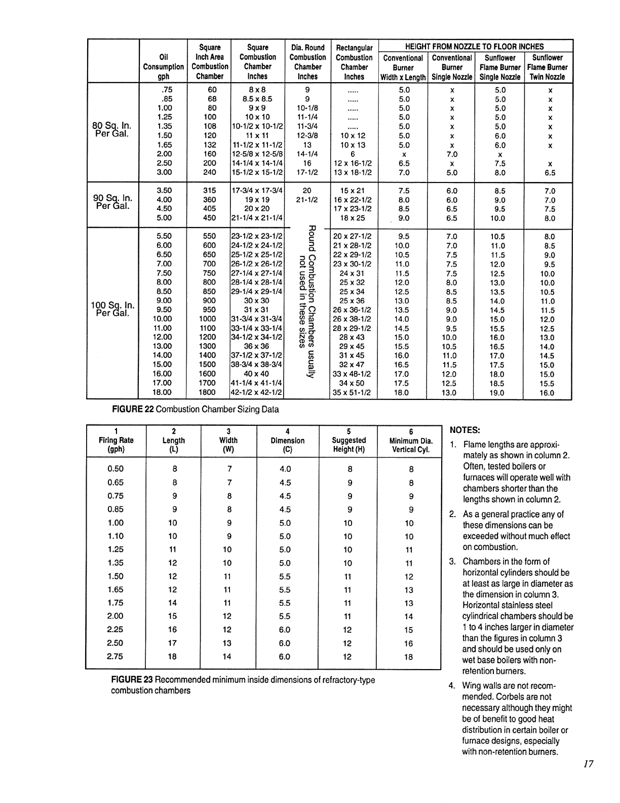
Walls. It is important that the walls of the
chamber be high enough to assist combustion, but
not so high as to interferewith the heat transfer
from the combustion products to the heat
exchanger.Figure 22 shows the height tobe used
based on the firing rate. The chamber wall should
be 2 to 2-1/4 times as high above the nozzle as it
is from the floor to the nozzle.
If the base of a heating unit has a tendency to
overheat, the walls should be 2-1/2 to 3 times the
height from floor to nozzle. This is sometimes a
problem in gravity type air duct systems or
boilers that have been converted from coal to oil.
Be sure to use insulation between the furnace and
chamber wall up to the top of the wall.
Space between the chamber wall and the heating
plant should be filled with an insulating material,
such as mica pellets--except in wet leg or wet
base boilers. Poor grade of backfill shortens
the life of the chamber, reduces the efficiency
at which the oil burns, and increases
combustion noise.
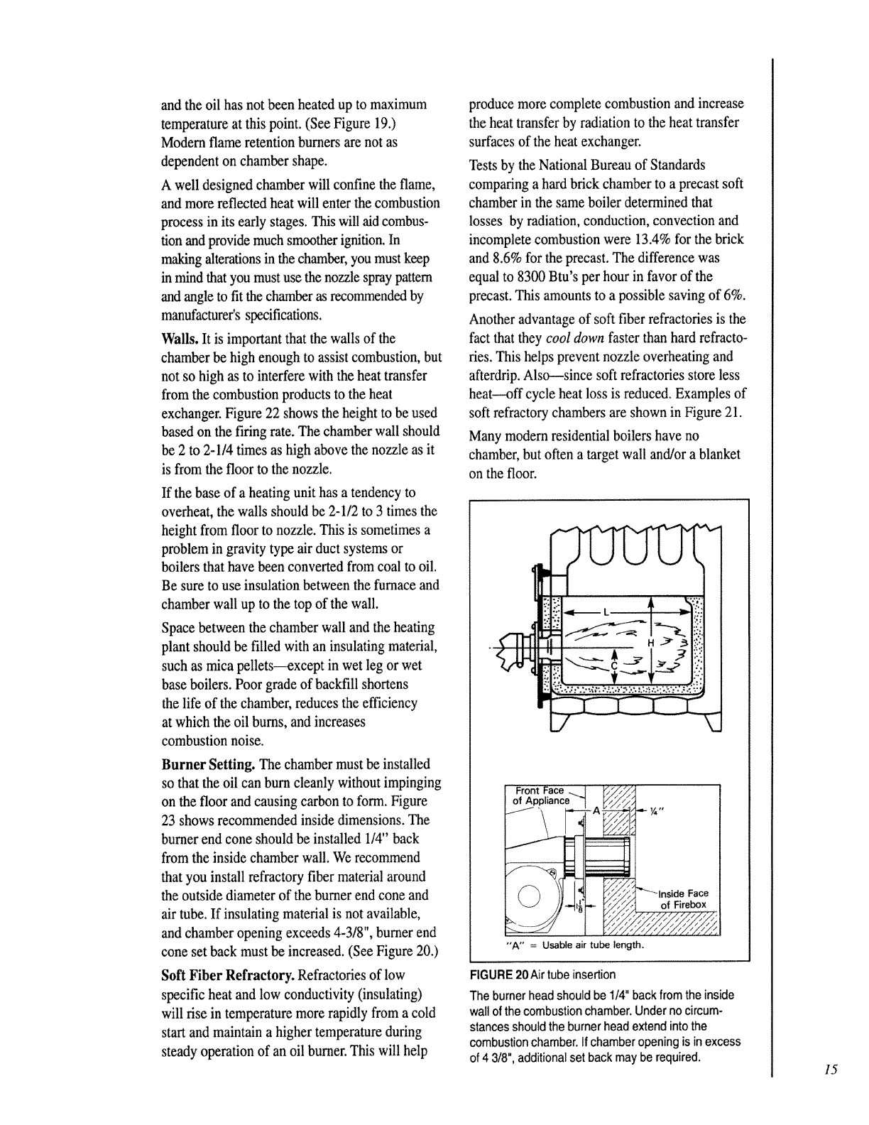
Burner Setting. The chamber must be installed
so that the oil can burn cleanly without impinging
on the floor and causing carbon to form. Figure
23 shows recommended inside dimensions. The
burner end cone should be installed 1/4" back
from the inside chamber wall. We recommend
that you install refractory fiber material around
the outside diameter of the burner end cone and
air tube. If insulating material is not available,
and chamber opening exceeds 4-3/8", burner end
cone set back must be increased. (See Figure 20.)
Soft Fiber Refractory. Refractories of low
specific heat and low conductivity (insulating)
will rise in temperature more rapidly from a cold
start and maintain a higher temperature during
steady operation of an oil burner. This will help
produce more complete combustion and increase
the heat transfer by radiation to the heat transfer
surfaces of the heat exchanger.
Tests by the National Bureau of Standards
comparing a hard brick chamber to a precast soft
chamber in the same boiler determined that
losses by radiation, conduction, convection and
incomplete combustion were 13.4% for the brick
and 8.6% for the precast. The difference was
equal to 8300 Btu's per hour in favor of the
precast. This amounts to a possible saving of 6%.
Another advantage of soft fiber refractories is the
fact that they cool down faster than hard refracto-
ries. This helps prevent nozzle overheating and
afterdrip. Also---since soft refractories store less
heat--off cycle heat loss is reduced. Examples of
soft refractory chambers are shown in Figure 21.
Many modern residential boilers have no
chamber, but often a target wall and/or a blanket
on the floor.
I
"A" = Usable air tube length.
Face
of Firebox
FIGURE 20 Air tube insertion
The burner head should be 1/4"back from the inside
wall of the combustion chamber. Underno circum-
stances should the burner head extend into the
combustion chamber. If chamber opening isin excess
of 4 3/8", additional set backmay be required. 15
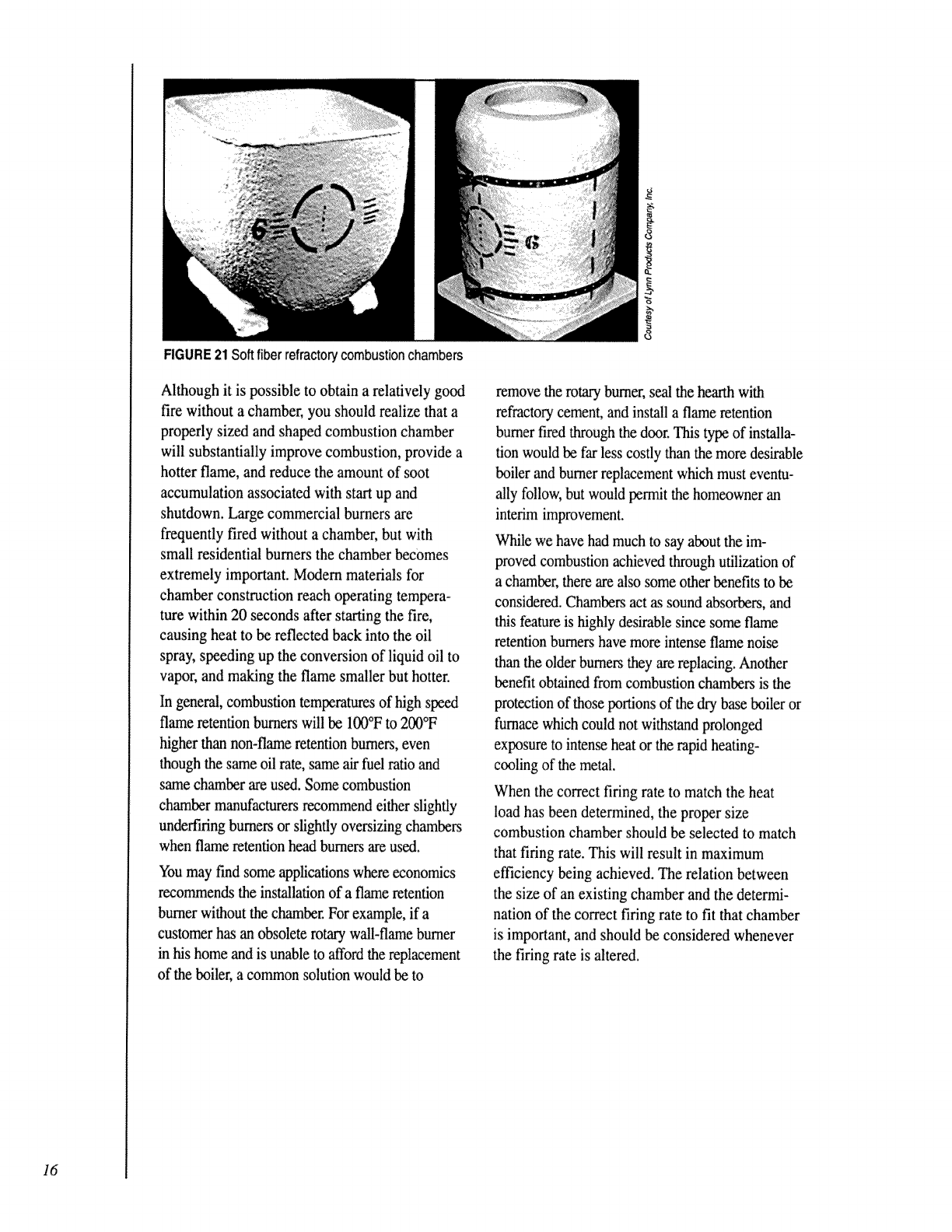
FIGURE 21 Soft fiber refractorycombustion chambers
Although it is possible to obtain a relatively good
fire without a chamber, you should realize that a
properly sized and shaped combustion chamber
will substantially improve combustion, provide a
hotter flame, and reduce the amount of soot
accumulation associated with sta_ up and
shutdown. Large commercial burners are
frequently fired without a chamber, but with
small residential burners the chamber becomes
extremely important. Modern materials for
chamber construction reach operating tempera-
ture within 20 seconds after starting the fire,
causing heat to be reflected back into the oil
spra}; speeding up the conversion of liquid oil to
vapor, and making the flame smaller but hotter.
In genera_l,combustion temperatures of high speed
flame retention burners will be II'X)°Fto 200°F
higher tl-_nnon-flame retentionburners, even
though the same oil rate, same a_ fuel ratio and
same chamber are used. Some combustion
chamber manufacturers recommend either slightly
undeffiring burners or slightly oversizing chambers
when flame retentionhead burners are useA.
Youmay find some applicationswhereeconomics
recommendsthe installationof a flameretention
burnerwithoutthe chamberFor example,if a
customerh_ an obsoleterotary wall-flameburner
in his home andis unable toaffordthe replacement
of the boiler,a commonsolutionwouldbe to
remove the rotary burner, seal the hearth with
refractory cement, and install a flame retention
burner fired through the door. This type of installa-
tion would be far less costly than the more desirable
boiler and burner replacement which must eventu-
ally follow, but would permit the homeowner an
interim improvement.
While we have had much to say about the im-
proved combustion achieved through utilization of
a chamber, there are also some other benefits to be
considered. Chambers act as sound absorbers, and
this feature is highly desirable since some flame
retention burners have more intense flame noise
than the older burners they are replacing. Another
benefit obNned from combustion chambers is the
protection of those portions of the dry base boiler or
fumace which could not withstand prolonged
exposure to intense heat or the rapid heating-
cooling of the metal.
When the correct firing rate to match the heat
load has been determined, the proper size
combustion chamber should be selected to match
that firing rate. This will result in maximum
efficiency being achieved. The relation between
the size of an existing chamber and the determi-
nation of the correct firing rate to fit that chamber
is important, and should be considered whenever
the firing rate is altered.
16
0 Sq. In.
erGal,
90 Sq. In.
Per Gal.
100 Sq. In.
Per Gal.
Oil
Consumption
gph
.75
.65
1,00
1.25
1.35
1.50
1.65
2.00
2.50
3,00
3_50
4.00
4.50
5.00
5,50
6.00
6.50
7.00
7.50
8,00
8.50
9.00
9,50
10,00
11.00
12,00
13.00
14,00
15_00
16.00
17.00
18.00
Square
InchArea
Combustion
Chamber
60
68
80
100
108
120
132
160
200
240
315
360
405
450
Square
Combustion
Chamber
Inches
8x8
8.5 x 8,5
9x9
lOx 10
10-1/2 x 10-1/2
1t x 11
1t-1/2 x 11-1/2
12_5/8x 12-5/8
14-1/4 x 14-1/4 i
15-1/2 x 15-1/21
Die.Round
Combustion
Chamber
Inches
9
9
10-1/8
11-1/4
11-3/4
12-3/8
13
t4-1/4
16
17-1/2
20
2!-1/2
Rectangular
Combustion
Chamber
Inches
10 x 12
10x13
6
12 x16-1/2
13x 18-1/2
15x21
16 x 22-1/2
17 x 23-1/2
18 x25
Conventional
Burner
Widthx Length
5.0
5.0
5,0
5.0
5.0
5.0
5.0
X
6.5
7.0
7.5
8,0
8.5
9.0
Conventional
Burner
SingleNozzle
HEIGHTFROMNOZZLETO FLOORINCHES
Sunflower
FlameBurner
TwinNozzle
X
X
X
X
X
X
X
X
X
X
X
7.0
X
5.0
Sunflower
FlameBurner
SingleNozzle
5.0
5.0
5,0
5.0
5.0
6.0
6.0
X
7.5
8.0
8.5
9.0
9,5
10.0
X
X
X
X
6.5
7,0
7.0
7.5
8.0
8.0
8.5
9.0
9.5
10_0
10.0
10.5
11.0
11.5
12.0
12.5
13.0
14.0
14.5
15.0
15.0
15.5
16.0
550
600
650
7O0
750
800
850
900
950
1000
1100
1200
1300
1400
1500
1600
1700
1800
17-3/4 x 17-3/4
19x 19
20x20
21-1/4 x 21-1/4
23-1/2 x 23-1/2
24-I/2 x 24-1/2
25-1/2 x 25-1/2
26-1/2 X 26-1/2
27-1/4 x 27-1/4
28-1/4 x 28-t/4
29-1/4 x 29-1/4
30 x 30
31 x 31
31-3/4 x 31-3/4
33-1/4 x 33-1/4
34-1/2 x 34-1/2
36x36
37-1/2 x 37-1/2
38-3/4 x 38-3/4
40 x 40
41-1/4 x 41-I/4
42-1/2 x 42-1/2
o
o.
oo
::tO
N_
C
20 x 27-1/2
2t x28_1/2
22 x 29-1/2
23 x30-1/2
24x31
25 x 32
25 x 34
25 x 36
26 x 36-1/2
26 x 38-1/2
28 x 29-1/2
28 x 43
29 x 45
31 x 45
32 x 47
33 x 48-1/2
34 x 50
35 x 51-1/2
9.5
10.0
10.5
11,0
1t .5
12.0
12.5
13,0
13.5
14.0
14,5
15.0
15,5
16.0
16.5
17.0
17.5
18.0
6.0
6_0
6.5
6.5
10.5
11.0
11.5
12.0
12,5
13.0
13.5
14.0
14.5
15.0
15.5
16.0
16.5
17.0
17.5
18.0
18.5
19.0
7.0
7.0
7,5
7.5
7.5
8.0
8,5
8,5
9.0
9.0
9.5
10.0
10.5
11.0
11,5
12.0
12.5
13.0
FIGURE 22 Combustion Chamber Sizing Data
23456
Length Dimension Suggested MinimumDia.
(L) (C) Height(H) VerticalCyL
1
FiringRate
(gph)
0.50
0.65
0.75
0.85
1.00
1.10
1,25
1,35
1.50
1.65
1.75
2.00
2.25
2.50
2,75
8
8
9
9
10
10
11
12
12
12
14
15
16
17
18
Width
(w)
7
7
8
8
9
9
10
10
11
11
11
12
12
13
14
4.0
4.5
4.5
4.5
5.0
5.0
5.0
5.0
5.5
5.5
5.5
5.5
6.0
6.0
6.0
8
9
9
9
10
10
10
10
11
11
11
11
12
12
12
8
8
9
9
10
10
11
11
12
13
13
14
15
16
18
FIGURE 23 Recommended minimum insidedimensions of refractory-type
combustion chambers
NOTES:
1. Flame lengths are approxi-
mately as shown in column 2.
Often, tested boilers or
furnaces will operate wel! with
chambers shorter than the
lengths shown in column 2.
2. As a general practice any of
these dimensions can be
exceeded without much effect
on combustion.
3. Chambers in theform of
horizontal cylinders should be
at least as large in diameter as
the dimension in column 3.
Horizontal stainless steel
cylindrical chambers should be
1 to 4 inches larger in diameter
than thefigures in column 3
and should be used only on
wet base boilers with non-
retention burners.
4. Wing walls are not recom-
mended. Corbels are not
necessary although they might
beof benefit to good heat
distribution in certain boiler or
furnace designs, especially
with non-retention burners.
17
HEAT EXCHANGERS
The next step in the operation of the heating
appliance is the transfer of heat energy from the
combustion gases to the air in the furnace or to
the water in the boiler. This is accomplished in
the heat exchanger, which is simply a wall which
keeps gases or liquids separated and allows heat
energy to flow out of the hot medium and into the
cooler medium. Heat is transferred in two ways:
I? Hot combustion gases directly contact the heat
exchanger surfaces and transfer heat.
•'Radiant energy in the combustion chamber
heats the heat exchanger surfaces (similar to
being heated by the sun). The selection of
wall material will depend on its ability to
easily pass heat, its cost, and several other
factors. This is a whole area of study in itself.
If the heat exchanger were a perfect transferer of
heat, all the energy in the combustion products
would be transferred to the distribution medium.
This would mean no losses of heat! With no heat
losses, the stack temperature would be reduced to
room temperature. Of course you know this is not
the actual case. Losses are caused by
!I' Temperature differences
•'Contact time
'It Insulation
The greater the temperature difference between
the combustion gases and the temperature of the
air or water to be heated, the more heat will be
transferred in a given time. There is very little
that can be done about the temperature of the air
or water to be heated, but if the temperature of
the combustion gases can be raised, more heat
would be transferred. This is another reason
why a high flame temperature from the burner
is desirable.
The longer the hot combustion gases are in
contact with the walls of the heat exchanger, the
more heat will be transferred. The scrubbing of
the heat exchanger walls by the combustion gases
is essential. This means that small flue passages
in the heat exchanger provide better contact
than wide open flue passages. With greater heat
exchanger surface area per volume of combus-
tion gas, more intimate contact of heat and
walls occurs.
Heat Exchanger Designs
Many types of heat exchangers--with varying
degrees of efficiency--are in use today. The
following are some major types:
Single-Pass, Vertical Tube
Exchangers (Boilers)
Hot gases flow through the boiler in only one
direction (up). (See Figure 24.)
Multi-Pass, Horizontal Tube
Exchanger (Boilers)
Hot gases flow upward--then change direction
and flow through horizontal tubes. (See
Figure 24.)
Oil Furnace Heat Exchangers
A typical oil furnace heat exchanger actually
consists of two exchangers. The hot gases first
enter the primary exchanger (inner cylinder), then
pass through a connector to the secondary
exchanger (outer cylinder). This provides
SINGLE-PASS,VERTICALTUBEEXCHANGER
\_ /
MULTI-PASS,HORIZONTALTUBE EXCHANGER
Heat Exchanger
Exhaust To Chimney
Boiler
Water
Gases
o_
18
FIGURE 24 Heatexchanger designs
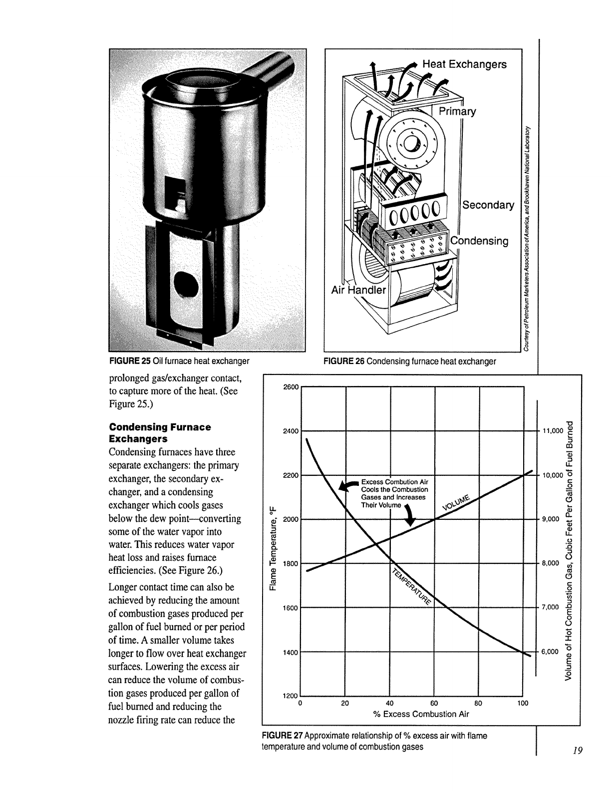
FIGURE 25 Oil furnace heat exchanger
prolonged gas/exchanger contact,
to capture more of the heat. (See
Figure 25.)
Condensing Furnace
Exchangers
Condensing furnaces have three
separate exchangers: the primary
exchanger, the secondary ex-
changer, and a condensing
exchanger which cools gases
below the dew point--converting
some of the water vapor into
water. This reduces water vapor
heat loss and raises furnace
efficiencies. (See Figure 26.)
Longer contact time can also be
achieved by reducing the amount
of combustion gases produced per
gallon of fuel burned or per period
of time. A smaller volume takes
longer to flow over heat exchanger
surfaces. Lowering the excess air
can reduce the volume of combus-
tion gases produced per gallon of
fuel burned and reducing the
nozzle firing rate can reduce the
Ai Handler
Heat Exchangers
Primary
3econdary
[ 11
Condensing
1
FIGURE26 Condensing furnace heat exchanger
lira Excess Combution Air
Cools the Combustion
Gases and Increases
_, Their Volume _Ikt
q_
0 20 40 60 80 100
% Excess Combustion Air
FIGURE 27Approximate relationship of % excess air with flame
temperature and volume of combustion gases
"O
11,000
io,ooo"6
t..-
o
9,000 _
._.9.
0
,8,000 {ff
O
{/)
7,000 -_
O
O
"6
3:
8,000 _
E
19
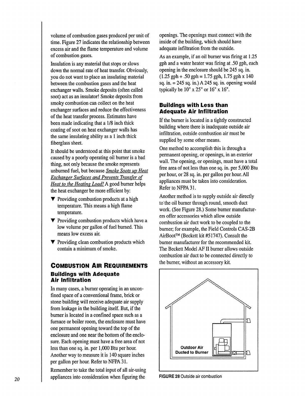
20
volume of combustion gases produced per unit of
time. Figure 27 indicates the relationship between
excess air and the flame temperature and volume
of combustion gases.
Insulation is any material that stops or slows
down the normal rate of heat transfer. Obviously,
you do not want to place an insulating material
between the combustion gases and the heat
exchanger walls. Smoke deposits (often called
soo0 act as an insulator! Smoke deposits from
smoky corr/bustion can collect on the heat
exchanger surfaces and reduce the effectiveness
of the heat transfer process. Estimates have
been made indicating that a 1/8 inch thick
coating of soot on heat exchanger walls has
the same insulating ability as a 1 inch thick
fiberglass sheet.
It should be understood at this point that smoke
caused by a poorly operating oil burner is a bad
thing, not only because the smoke represents
unburned fuel, but because .SmokeSoots up Heat
_er Surfaces and Prevents Transfer of
Heat to the Heating Load! A good burner helps
the heat exchanger be more efficient by:
YProviding combustion products at a high
temperature. This means a high flame
temperature.
'V' Providing combustion products which have a
low volume per gallon of fuel burned. This
means low excess air.
V Providing clean combustion products which
contain a minimum of smoke.
COMBUSTION AIR REQUIREMENTS
Buildings with Adequate
Air Infiltration
In many cases, a burner operating in an uncon-
fined space of a conventional frame, brick or
stone building will receive adequate air supply
from leakage in the building itself. But, if the
burner is located in a confined space such as a
furnace or boiler room, the enclosure must have
one permanent opening toward the top of the
enclosure and one near the bottom of the enclo-
sure. Each opening must have a free area of not
less than one sq. in. per 1,000 Btu per hour.
Another way to measure it is 140 square inches
per gallon per hour. Refer to NFPA 31.
Remember to take the total input of all air-using
appliances into consideration when figuring the
openings. The openings must connect with the
inside of the building, which should have
adequate infiltration from the outside.
As an example, if an oil burner was firing at 1.25
gph and a water heater was firing at .50 gph, each
opening in the enclosure should be 245 sq. in.
(1.25 gph + .50 gph = 1.75 gph, 1.75 gph x 140
sq. in. = 245 sq. in.) A 245 sq. in. opening would
typically be 10" x 25" or 16" x 16".
Buildings with Less than
Adequate Air Infiltration
If the burner is located in a tightly"constnacted
building where there is inadequate outside air
infiltration, outside combustion air must be
supplied by some other means.
One method to accomplish this is through a
permanent opening, or openings, in an exterior
wall. The opening, or openings, must have a total
free area of not less than one sq. in. per 5,000 Btu
per hour, or 28 sq. in. per gallon per hour. All
appliances must be taken into consideration.
Refer to NFPA 31.
Another method is to supply outside air directly
to'the oil burner through round, smooth duct
work. (See Figure 28.) Some burner manufactur-
ers offer accessories which allow outside
combustion air duct work to be coupled to the
burner; for example, the Field Controls CAS-2B
AirBoot TM (Beckett kit #51747). Consult the
burner manufacturer for the recommended kit.
The Beckett Model AF II burner allows outside
combustion air duct to be connected directly to
the bumer, without an accessory kit.
Outdoor Air
Ducted to Burner
FIGURE28 Outside air combustion
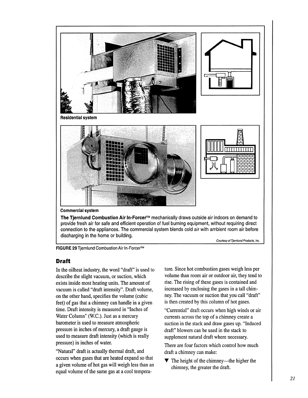
Ii
Residential system
The Tjernlund Combustion Air In-ForcerTM mechanically drawsoutside air indoors on demand to
providefresh airfor safe andefficientoperationof fuel burning equipment,withoutrequiringdirect
connectionto the appliances. The commercialsystemblendscoldair withambient roomair before
discharginginthe homeor building.
Courtesy el Tlemlund Products, In&
FIGURE 29 TjernlundCombustion Air In-ForcerTM
Draft
In the oilheat industry, the word "draft" is used to
describe the slight vacuum, or suction, which
exists inside most heating units. The amount of
vacuum is called "draft intensity". Draft volume,
on the other hand, specifies the volume (cubic
feet) of gas that a chimney can handle in a given
time. Draft intensity is measured in "Inches of
Water Column" (W.C). Just as a mercury
barometer is used to measure atmospheric
pressure in inches of mercury, a draft gauge is
used to measure draft intensity (which is really
pressure) in inches of water.
"Natural" draft is actually thermal draft, and
occurs when gases that are heated expand so that
a given volume of hot gas will weigh less than an
equal volume of the same gas at a cool tempera-
ture. Since hot combustion gases weigh less per
volume than room air or outdoor air, they tend to
rise. The rising of these gases is contained and
increased by enclosing the gases in a tall chim-
ney. The vacuum or suction that you call "draft"
is then created by this column of hot gases.
"Currential" draft occurs when high winds or air
currents across the top of a chimney create a
suction in the stack and draw gases up. "Induced
draft" blowers can be used in the stack to
supplement natural draft where necessary.
There are four factors which control how much
draft a chimney can make:
_' The height of the chimney--the higher the
chimney, the greater the draft.
21
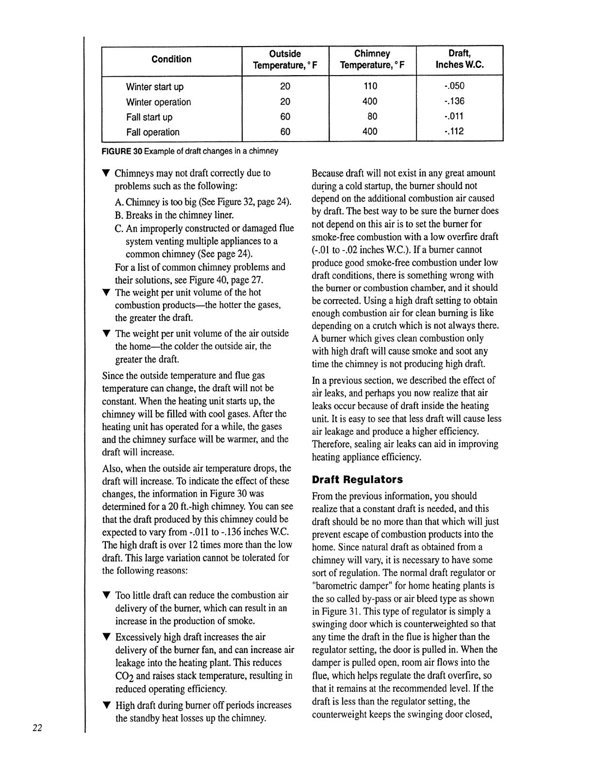
22
Outside
Condition Inches W:C.
Winter start up
Winter operation
Fall start up
Fall operation
20
20
60
6O
FIGURE 30 Exampleof draft changesinachimney
110
400
8O
400
-.050
-.136
-.011
-.112
V Chimneys may not draft correctly due to
problems such as the following:
A. Chirvmey is too big (See Figure 32, page 24).
B. Breaks in the chimney liner.
C. An improperly constructed or damaged flue
system venting multiple appliances to a
common chimney (See page 24).
For a list of common chimney problems and
their solutions, see Figure 40, page 27.
'_' The weight per unit volume of the hot
combustion products--the hotter the gases,
the greater the draft.
V The weight per unit volume of the air outside
the home--the colder the outside air, the
greater the draft.
Since the outside temperature and flue gas
temperature can change, the draft will not be
constant. When the heating unit starts up, the
chimney will be filled with cool gases. After the
heating unit has operated for a while, the gases
and the chimney surface will be warmer, and the
draft will increase.
Also, when the outside air temperature drops, the
draft will increase. To indicate the effect of these
changes, the information in Figure 30 was
determined for a 20 ft.-high chimney. You can see
that the draft produced by this chimney could be
expected to vary from -.011 to -.136 inches W.C.
The high draft is over 12 times more than the low
draft. This large variation cannot be tolerated for
the following reasons:
'I' Too little draft can reduce the combustion air
delivery of the burner; which can result in an
increase in the production of smoke.
T Excessively high draft increases the air
delivery of the burner fan, and can increase air
leakage into the heating plant. This reduces
CO 2 and raises stack temperature, resulting in
reduced operating efficiency.
'_' High draft during burner off periods increases
the standby heat losses up the chirruley.
Because draft will not exist in any great amount
during a cold startup, the burner should not
depend on the additional combustion air caused
by draft. The best way to be sure the burner d_s
not depend on this air is to set the burner for
smoke-free combustion with a low overfire draft
(-.01 to -.02 inches W.C.). If a burner cannot
produce good smoke-free combustion under low
draft conditions, there is something wrong with
the burner or combustion chamber, and it should
be corrected. Using a high draft setting to obtain
enough combustion air for clean burning is like
depending on a crutch which is not always there.
A burner which gives clean combustion only
with high draft will cause smoke and soot any
time the chimney is not producing high draft.
In a previous section, we described the effect of
a]r leaks, and perhaps you now realize that air
leaks occur because of draft inside the heating
unit. It is easy to see that less draft will cause less
air leakage and produce a higher efficiency.
Therefore, sealing air leaks can aid in improving
heating appliance efficiency.
Draft Regulators
From the previous information, you should
realize that a constant draft is needed, and this
draft should be no more than that which will just
prevent escape of combustion products into the
home. Since natural draft as obtained from a
chimney will vary, it is necessary to have some
sort of regulation. The normal draft regulator or
"barometric damper" for home heating plants is
the so called by-pass or air bleed type as shown
in Figure 31. This type of regulator is simply a
swinging door which is counterweighted so that
any time the draft in the flue is higher than the
regulator setting, the door is pulled in. When the
damper is pulled open, room air flows into the
flue, which helps regulate the draft overfire, so
(hat it remains at the recommended level. If the
draft is less than the regulator setting, the
counterweight keeps the swinging door closed,
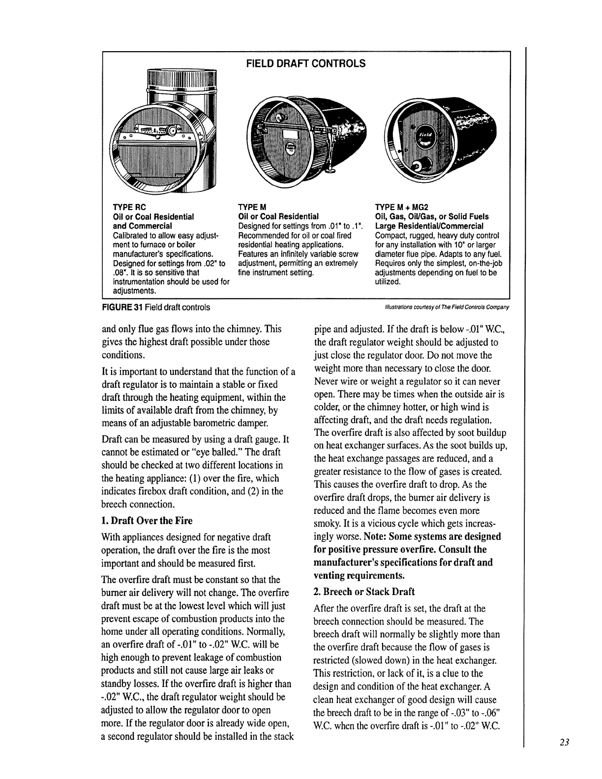
FIELD DRAFT CONTROLS
TYPE RC
Oil or Coal Residential
and Commercial
Calibratedto alloweasyadjust-
mentto furnace orboiler
manufacturer's specifications.
Designedfor settingsfrom .02"to
.08".It is sosensitivethat
instrumentationshouldbe usedfor
adjustments.
TYPE M
Oil or Coal Residential
Designedforsettingsfrom.01"to.l".
Recommendedfor oil or coal fired
residentialheatingapplications.
Featuresan infinitelyvariablescrew
adjustment,permittingan extremely
fine instrumentsetting.
TYPE M +MG2
Oil,Gas, Oil/Gas,or Solid Fuels
LargeResidential/Commercial
Compact,rugged,heavydutycontrol
for anyinstallationwith10"orlarger
diameterflue pipe.Adapts toany fuel.
Requiresonlythesimplest,on-the-job
adjustmentsdependingon fuel to be
utilized.
FIGURE 31 Field draft controls Illustrationscourtesy of The Field Controls Company
and only flue gas flows into the chimney. This
gives the highest draft possible under those
conditions.
It is important to understand that the function of a
draft regulator is to maintain a stable or fixed
draft through the heating equipment, within the
lirr&s of available draft from the chimney, by
means of an adjustable barometric damper.
Draft can be measured by using a draft gauge. It
cannot be estimated or "eye balled." The draft
should be checked at two different locations in
the heating appliance: (1) over the fire, which
indicates firebox draft condition, and (2) in the
breech connection.
1. Draft Over the Fire
With appliances designed for negative draft
operation, the draft over the fire is the most
important and should be measured first.
The overfire draft must be constant so that the
burner air delivery will not change. The overfire
draft must be at the lowest level which will just
prevent escape of combustion products into the
home under all operating conditions. Normally,
an overfire draft of -,0l" to -.02" W.C. will be
high enough to prevent leakage of combustion
products and still not cause large air leaks or
standby losses. If the overfire draft is higher than
-.02" W.C., the draft regulator weight should be
adjusted to allow the regulator door to open
more. If the regulator door is already wide open,
a second regulator should be installed in the stack
pipe and adjusted. If the draft is below -.01"V_.C,
the draft regulator weight should be adjusted to
just close the regulator door. Do not move the
weight more than necessary to close the door.
Never wire or weight a regulator so it can never
open. There may be times when the outside air is
colder, or the chimney hotter, or high wind is
affecting draft, and the draft needs regulation.
The overfire draft is also affected by soot buildup
on heat exchanger surfaces. As the soot builds up,
the heat exchange passages are reduced, and a
greater resistance to the flow of gases is created.
This causes the overfire draft to drop. As the
overfire draft drops, the burner air delivery is
reduced and the flame becomes even more
smoky. It is a vicious cycle which gets increas-
ingly worse. Note: Some systems are designed
for positive pressure overfire. Consult the
manufacturer's specifications for draft and
venting requirements.
2. Breech or Stack Draft
After the overfire draft is set, the draft at the
breech connection should be measured. The
breech draft will normally be slightly more than
the overfire draft because the flow of gases is
restricted (slowed down) in the heat exchanger.
This restriction, or lack of it, is a clue to the
design and condition of the heat exchanger. A
clean heat exchanger of good design will cause
the breech draft to be in the range of -.03" to -.06"
W.C. when the overfire draft is -.01" to -.02" W.C.
23
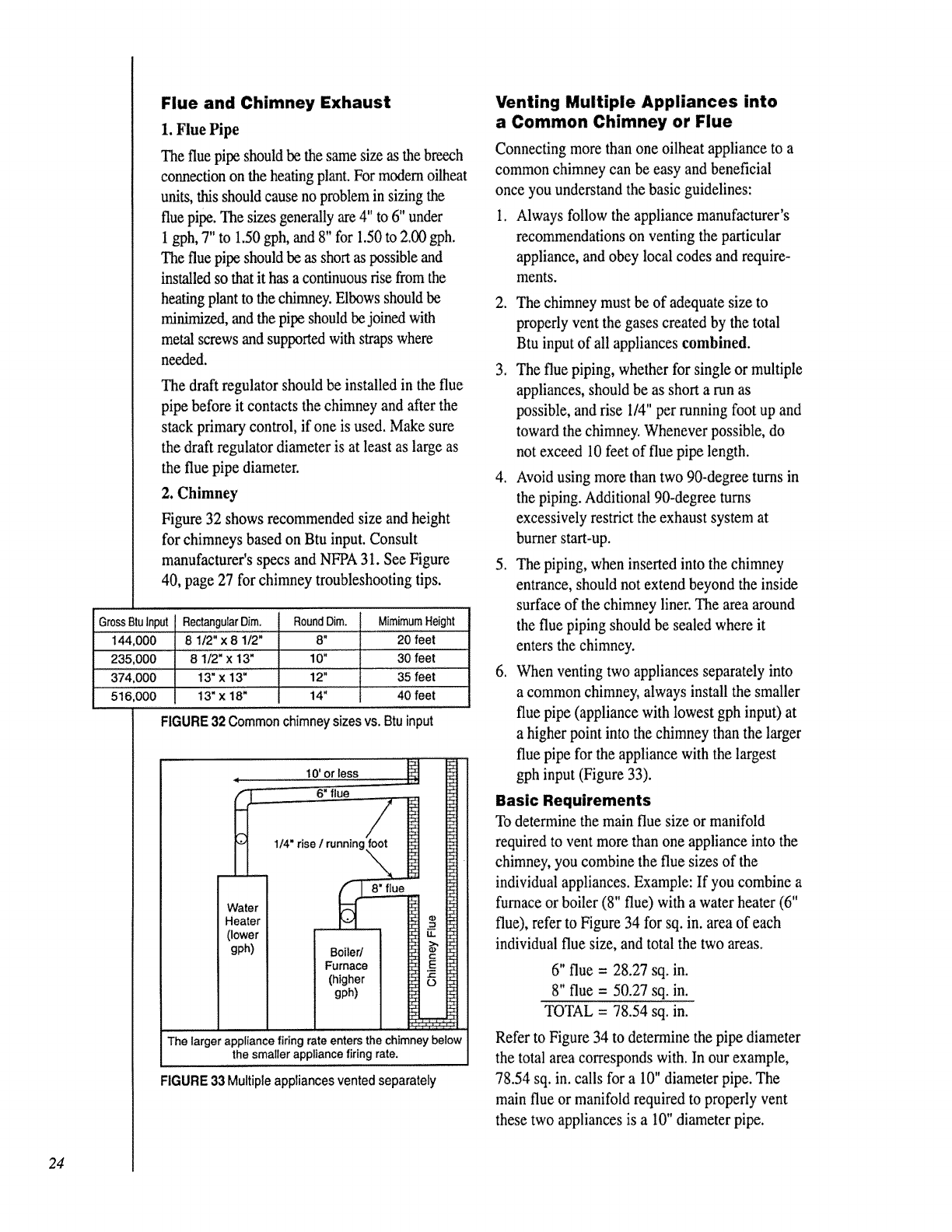
24
Flue and Chimney Exhaust
1. Flue Pipe
The flue pipe should be the same size as the breech
connection on the heating plant. For modem oilheat
units, this should cause no problem in sizing the
flue pipe. The sizes generally are 4" to 6" under
1 gph, 7" to 1.50 gph, and 8" for 1.50 to ZOOgph.
The flue pipe should be as short as possible and
installed so that it has a continuous rise from the
heating plant to the chimney. Elbows should be
minirrfized, and the pipe should be joined with
metal screws and supported with straps where
needed.
The draft regulator should be installed in the flue
pipe before it contacts the chimney and after the
stack primar 7 control, if one is used. Make sure
the draft regulator diameter is at least as large as
the flue pipe diameter.
2. Chimney
Figure 32 shows recommended size and height
for chimneys based on Btu input. Consult
manufacturer's specs and NFPA 31. See Figure
40, page 27 for chimney troubleshooting tips.
GrossBtuInput RectangularDim. RoundDim. MimimurnHeight
144,000 8 112"x 8 1/2" 8" 20 feet
235,000 8 1/2" x 13" 1O" 30 feet
374,000 13" x 13" 12" 35 feet
516,000 13" x 18" 14" 40 feet
FIGURE 32 Common chimney sizes vs. Btu input
10' ortess
6" flue
H
(u
Boiler/
Furnace
(higher
gph)
The larger appliance firing rate enters the chimney below
the smaller appliance firing rate.
FIGURE 33 Multiple appliances vented separately
Venting Multiple Appliances into
a Common Chimney or Flue
Connecting more than one oilheat appliance to a
common chimney can be easy and beneficial
once you understand the basic guidelines:
1. Always follow the appliance manufacturer's
recommendations on venting the particular
appliance, and obey local codes and require-
ments.
2. The chimney must be of adequate size to
properly vent the gases created by the total
Btu input of all appliances combined.
3. The flue piping, whether for single or multiple
appliances, should be as short a run as
possible, and rise I/4" per running foot up and
toward the chimney. Whenever possible, do
not exceed 10 feet of flue pipe length.
4, Avoid using more than two 90-degree turns in
the piping. Additional 90-degree turns
excessively restrict the exhaust system at
burner start-up.
5. The piping, when inserted into the chimney
entrance, should not extend beyond the inside
surface of the chimney liner. The area around
the flue piping should be sealed where it
enters the chimney.
6. When venting two appliances separately into
a common chimney, always install the smaller
flue pipe (appliance with lowest gph input) at
a higher point into the chimney than the larger
flue pipe for the appliance with the largest
gph input (Figure 33).
Basic Requirements
To determine the main flue size or manifold
required to vent more than one appliance into the
chimney, you combine the flue sizes of the
individual appliances. Example: If you combine a
furnace or boiler (8" flue) with a water heater (6"
flue), refer to Figure 34 for sq. in. area of each
individual flue size, and total the two areas.
6" flue = 28.27 sq. in.
8" flue = 50.27 sq. in.
TOTAL = 78.54 sq. in.
Refer to Figure 34 to determine the pipe diameter
the total area corresponds with. In our example,
78.54 sq. in. calls for a 10" diameter pipe. The
main flue or manifold required to properly vent
these two appliances is a 10" diameter pipe.
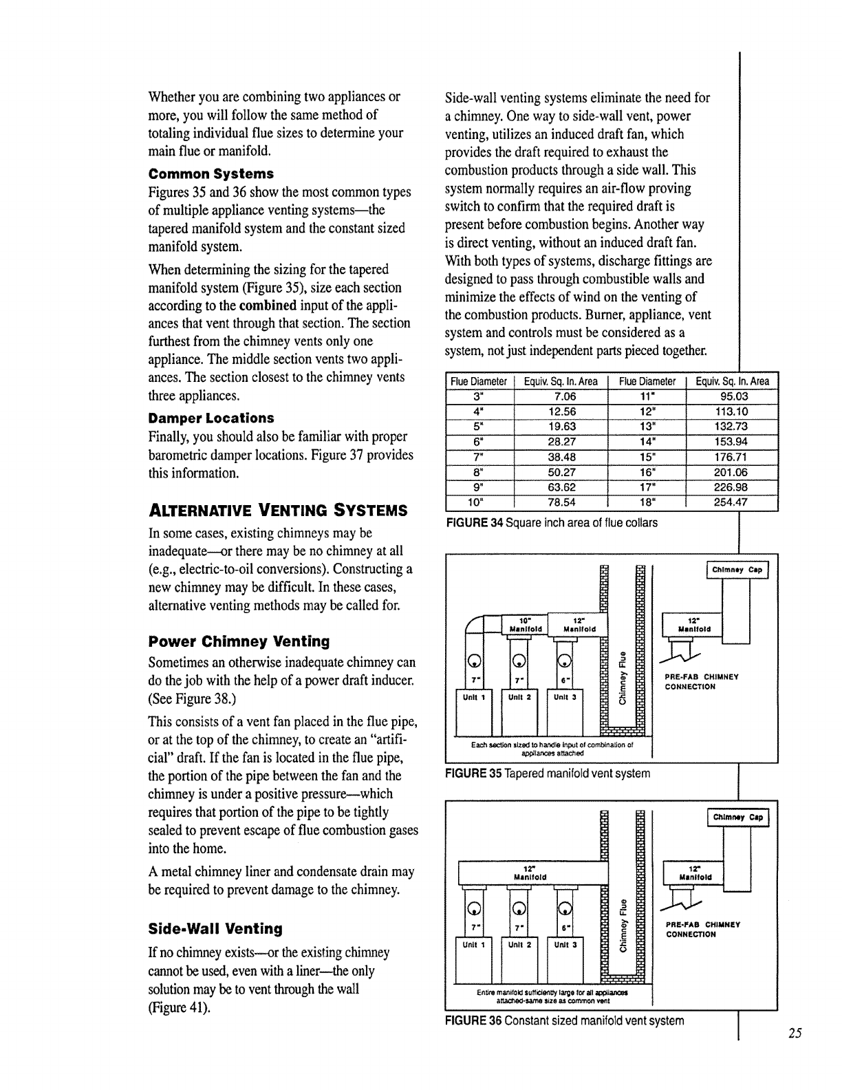
Whetheryouarecombiningtwoappliancesor
more,youwillfollowthesamemethodof
totalingindividualfluesizestodetermineyour
mainflueormanifold.
Common Systems
Figures 35 and 36 show the most common types
of multiple appliance venting systems the
tapered manifold system and the constant sized
manifold system.
When determining the sizing for the tapered
manifold system (Figure 35), size each section
according to the combined input of the appli-
ances that vent through that section. The section
furthest from the chimney vents only one
appliance. The middle section vents two appli-
ances. The section closest to the chimney vents
three appliances.
Damper Locations
Finally, you should also be familiar with proper
barometric damper locations. Figure 37 provides
this information.
ALTERNATIVE VENTING SYSTEMS
In some cases, existing chimneys may be
inadequate----or there may be no chimney at all
(e.g., electric-to-oil conversions). Constructing a
new chimney may be difficult. In these cases,
alternative venting methods may be called for.
Power Chimney Venting
Sometimes an otherwise inadequate chimney can
do the job with the help of a power draft inducer.
(See Figure 38.)
This consists of a vent fan placed in the flue pipe,
or at the top of the chimney, to create an "artifi-
cial" draft. If the fan is located in the flue pipe,
the portion of the pipe between the fan and the
chimney is under a positive pressure--which
requires that portion of the pipe to be tightly
sealed to prevent escape of flue combustion gases
into the home.
A metal chimney liner and condensate drain may
be required to prevent damage to the chimney.
Side-Wall Venting
If no chimney exists--or the existing chimney
cannot be used, even with a liner---_.heonly
solution may be to vent through the wall
(Figure41).
Side-wall venting systems eliminate the need for
a chimney. One way to side-wall vent, power
venting, utilizes an induced draft fan, which
provides the draft required to exhaust the
combustion products through a side wall. This
system normally requires an air-flow proving
switch to confirm that the required draft is
present before combustion begins. Another way
is direct venting, without an induced draft fan.
With both types of systems, discharge fittings are
designed to pass through combustible walls and
minimize the effects of wind on the venting of
the combustion products. Burner, appliance, vent
system and controls must be considered as a
system, not just independent parts pieced together.
Flue Diameter Equiv.Sq.In, Area
3" 7.06
4" 12.56
5" 19.63
6" 28.27
7" 38.48
8" 50.27
9" 63.62
10" 78,54
Flue Diameter Equiv.Sq. In. Area
11" 95.03
12" 113,10
13" 132,73
14" 153.94
15" , 176.71
16" 201.06
17" 226.98
18" 254.471
FIGURE 34 Square inch area of flue collars
J
-" 7" 6"
U.II1 "U.,'_2-- _"tjn_l 3"
....ola j
i i l_ PRE-FAa CHIMNEY
_l _" co...cTio.
ii
Ea,ctt _on sL__:_ to h;/ilcJle It_mt Ot ¢omb_nalJon of
,a_p_l,_',c6'.sattac_e_
FIGURE35 Tapered manifold vent system
:1
1
1
1
i
i
i©
I7" 7" 6"
i
Unll 1 Unit 2 Unit 3
Mlnlfold
PRE-FAB CHIMNEY
CONNECTION
E_t6re m_tfold suff_tty t al"ga for a_l
a_'_,:Fsan_ _et as _mtr_ vent
FIGURE36Constantsizedmanifoldventsystem 25
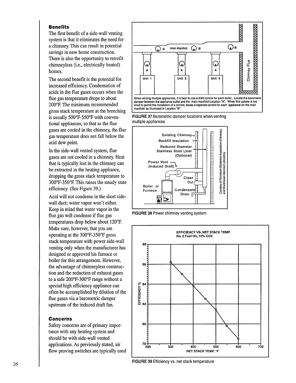
Benefits
The first benefit of a side-wall venting
system is that it eliminates the need for
a chirrmey. This can result in potential
savings in new home construction.
There is also the opportunity to retrofit
chimneyless (i.e., electrically heated)
homes.
The second benefit is the potential for
increased efficiency. Condensation of
acids in the flue gases occurs when the
flue gas temperature drops to about
200°E The minimum recormnended
gross stack temperature at the breeching
is usually 500°F-550°F with conven-
tional appliances, so that as the flue
gases are cooled in the chimney, the flue
gas temperature does not fall below the
acid dew point.
In the side-wall vented system, flue
gases are not cooled in a chimney. Heat
that is typically test in the chimney can
be extracted in the heating appliance,
dropping the gross stack temperature to
300°F-350°E This raises the steady state
efficiency. (See Figure 39.)
Acid will not condense in the short side-
wall duct; water vapor won't either.
Keep in mind that water vapor in the
flue gas will condense if flue gas
temperatures drop below about 120°E
Make sure, however, that you are
operating at the 300°F-350°F gross
stack temperature with power side-wall
venting only when the manufacturer has
designed or approved his furnace or
boiler for this arrangement. However,
the advantage of chimneyless construc-
tion and the reduction of exhaust gases
to a safe 200°F-300°F range without a
special high efficiency appliance can
often be accomplished by dilution of the
flue gases via a barometric damper
upstream of the induced draft fan.
Concerns
Safety concerns are of primary impor-
tance with any heating system and
should be with side-wall vented
applications. As previously stated, air
flow proving switches are typically used
f
/
1©
!A
-1 I
IUnit
i
When venting multiple _koplianses, it is best to use a draft control for each boiler, Locate the barometric
damper between the appliar_e outlet and the main manifoTd-Location *AL When his uptake is too
short to permit the installation of a control k_,.,ateaseperate control for each appliance On the main
manifold as iUustrated in Local° "B',
FIGURE 37 Barometric damper locations when venting
multiple appliances
Existing Chimney..,
Backfill Insulation -- •
Reduced Diameter
Stainless Steel Liner- --
(Optional)
Power Vent
(Induced Draft) .
IF--'li out_
Boiler or It II ]T-
Furnaoe tL--JI C°ndensat_tL_
_ D_ain_
FIGURE 38 Power chimney venting system
EFFICIENCY VS, NET STACK TEMP.
No. 2 Fuel Oi1,12% C02
88
L
ILl
6
E
200 300 400 500 600 700
NET STACK TEMP. *F
26 FIGURE 39 Efficiency vs. net stack temperature
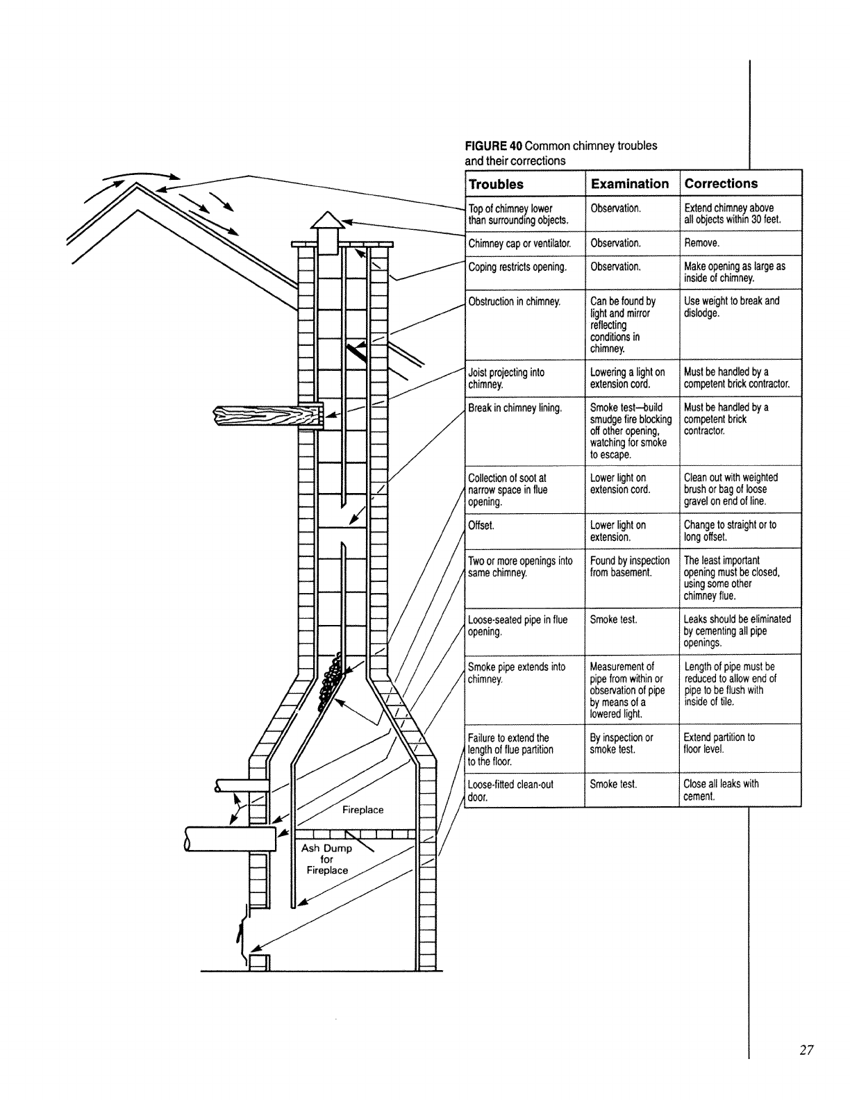
Fireplace
Ash Dump
for
Fireplace
FIGURE 40 Common chimneytroubles
and theircorrections
Troubles
Topofchimneylower
thansurroundingobjects.
Chimneycaporventilator,
Copingrestrictsopening.
Obstructionin chimney.
Joist projectinginto
chimney.
Examination
Observation,
Observation,
Observation.
Can be foundby
lightandmirror
reflecting
conditionsin
chimney.
Loweringa light on
extensioncord,
Corrections
Extendchimneyabove
allobjectswithtn30feet.
Remove.
Makeopeningaslargeas
insideofchimney.
Useweighttobreakand
dislodge.
Mustbehandledbya
competentbrickcontractor.
Breakin chimneylining.
Collectionofsootat
narrowspaceinflue
opening.
Offset.
Twoormoreopeningsinto
samechimney,
Loose-seatedpipeinflue
opening.
Smokepipeextendsinto
chimney.
Failureto extendthe
engthof fluepartition
:othe floor.
Loose4ittedclean-out
door
Smoketest--bui!d Must_ handledbya
smudgefireblocking
offotheropening,
watchingforsmoke
to escape.
Lowerlighton
extensioncord.
Lowerlighton
extension.
Foundby inspection
frombasement.
Smoketest.
Measurementof
' pipefrom withinor
observationof pipe
by meansof a
loweredlight.
Byinspectionor
smoketesL
Smoketest.
competentbrick
contractor.
Cleanout withweighted
brushor bagof loose
gravelonendof line.
Changeto straightorto
longoffset.
Theleastimportant
openingmustbeclosed,
us=ngsomeother
chimneyflue,
Leaksshouldbe eliminated
bycementingall pipe
openings.
Lengthof pipemustbe
reducedto allow endof
pipeto be flushwith
insideof tile.
Extendpartitionto
floor level.
Closeall leakswith
cement.
2F
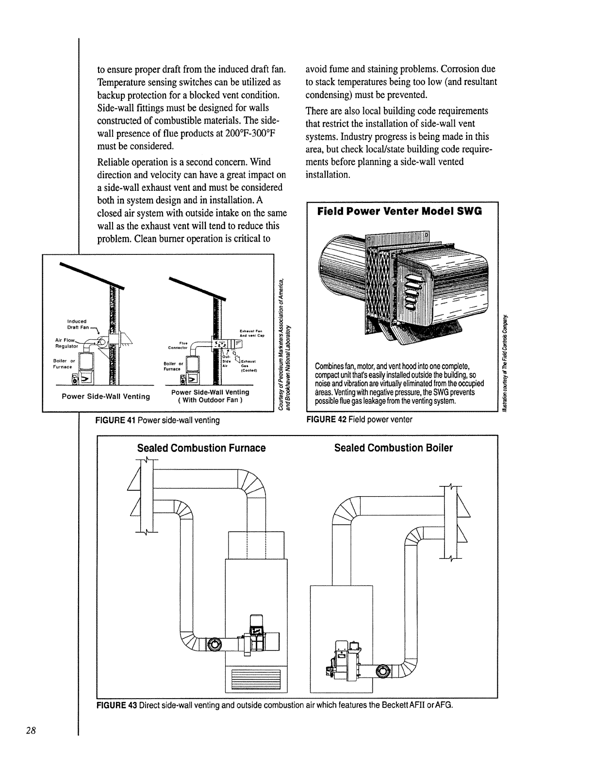
28
to ensure proper draft from the induced draft fan.
Temperature sensing switches can be utilized as
backup protection for a blocked vent condition.
Side-wall fittings must be designed for walls
constructed of combustible materials. The side-
wall presence of flue products at 200°F-300°F
must be considered.
Reliable operation is a second concern. Wind
direction and velocity can have a great impact on
a side-wall exhaust vent and must be considered
both in system design and in installation. A
closed air system with outside intake on the same
wall as the exhaust vent will tend to reduce this
problem. Clean burner operation is critical to
Power Side-Wall Venting Power Side-Wall Venting
( With Outdoor Fan )
FIGURE 41 Power side-wall venting
x
avoid fume and staining problems, Corrosion due
to stack temperatures being too low (and resultant
condensing) must be prevented.
There are also local building code requirements
that restrict the installation of side-wall vent
systems. Industry progress is being made in this
area, but check local/state building code require-
ments before planning a side-wall vented
installation.
Field Power Venter Model SWG
Combinesfan,motor,andventhoodintoonecomplete,
compactunitthatseasilyinstalledoutsidethebuilding,so
noiseandvibrationarevirtuallyeliminatedfromtheoccupied
areas.Ventingwithnegativepressure,theSWGprevents
possiblefluegasleakagefromtheventingsystem.
FIGURE 42 Field power venter
Sealed Combustion Furnace
F
Sealed Combustion Boiler
FIGURE 43 Direct side-wall venting and outside combustion airwhich features the BeckettAFII orAFG.
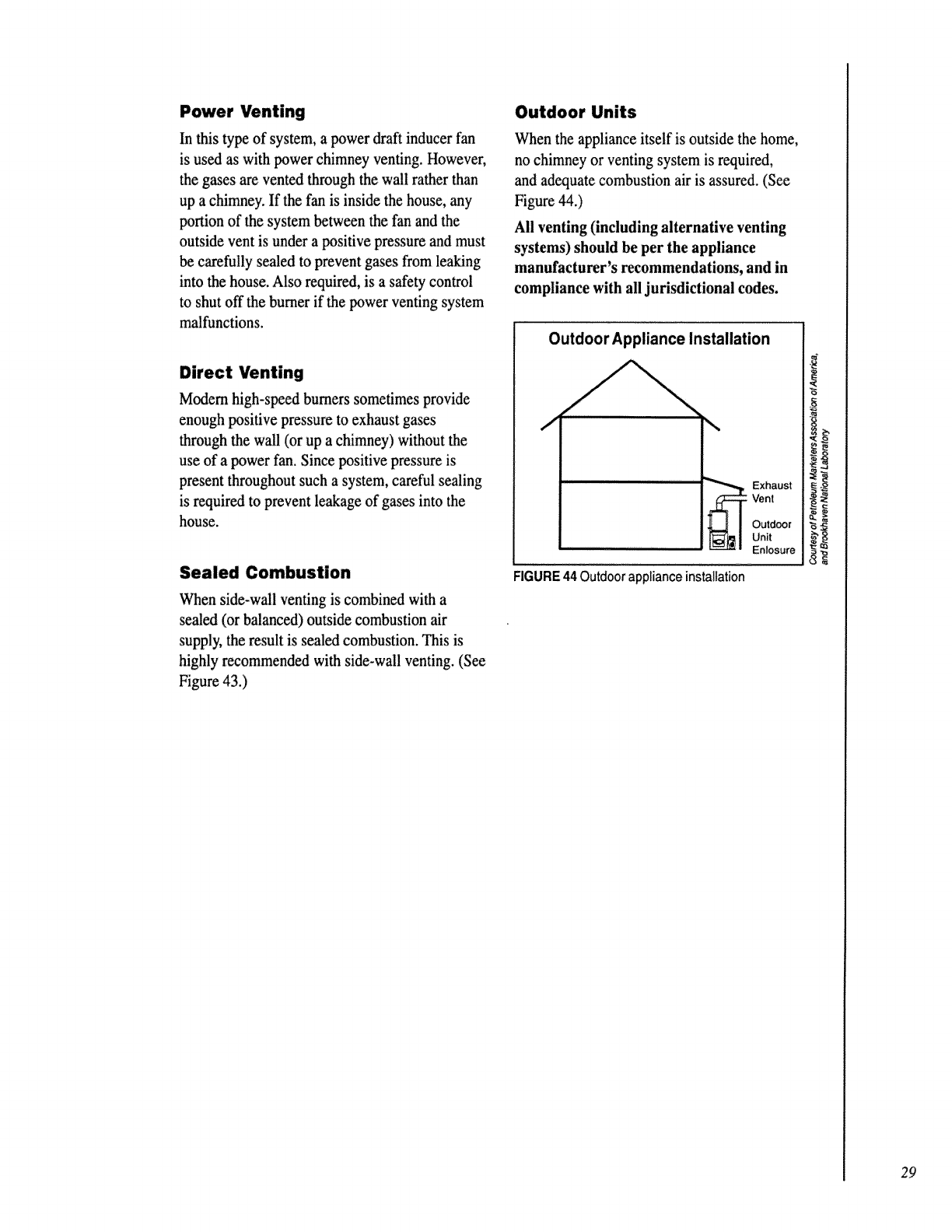
Power Venting
In this type of system, a power draft inducer fan
is used as with power chimney venting. However,
the gases are vented through the wall rather than
up a chimney. If the fan is inside the house, any
portion of the system between the fan and the
outside vent is under a positive pressure and must
be carefully sealed to prevent gases from leaking
into the house. Also required, is a safety control
to shut off the burner if the power venting system
malfunctions.
Direct Venting
Modem high-speed burners sometimes provide
enough positive pressure to exhaust gases
through the wall (or up a chimney) without the
use of a power fan. Since positive pressure is
present throughout such a system, careful sealing
is required to prevent leakage of gases into the
house.
Sealed Combustion
When side-wall venting is combined with a
sealed (or balanced) outside combustion air
supply, the result is sealed combustion. This is
highly recommended with side-wall venting. (See
Figure 43.)
Outdoor Units
When the appliance itself is outside the home,
no chimney or venting system is required,
and adequate combustion air is assured. (See
Figure 44.)
All venting (including alternative venting
systems) should be per the appliance
manufacturer's recommendations, and in
compliance with all jurisdictional codes,
Outdoor Appliance Installation
J\
_ xhaust
Vent
Outdoor
Unit
Enlosure
FIGURE44 Outdoor applianceinstallation
29
30
%DEFINITION OF
VARIOUS TYPES OF
EFFICIENCY
When the word efficiency is used, do you know
what is meant? By definition, efficiency is a
measure of how well something is produced as
compared with what went into producing it. In
terms of heating systems, efficiency is a measure
of how well energy is transferred from one form
or place to another form or place. In general, the
energy output of a machine or device is compared
with the energy input:
useful energy output
Efficiency =
total energy input
For residential heating appliances, the measure-
ment of efficiency can be confusing, as there are
several different efficiencies that can be dis-
cussed. Because of this, it is important to
distinguish between the different efficiencies and
understand the specific meaning of each.
COMBUSTION EFFICIENCY
Combustion efficiency characterizes the effec-
tiveness of the combustion process in converting
the chemical energy of the fuel to heat. You may
be surprised to learn that the combustion effi-
ciency of oil burners is quite high--usually 98 to
100 percent. This means that almost all of the
chemical energy available in the fuel is changed
into heat energy of the combustion products,
Even in the case of a smoky flame, the amount of
energy lost because of unburned carbon is very
low. In fact, even with a smoke number of 9, the
amount of energy lost is found to be about 0.1
percent.
At this point, you may be wondering why so
much attention is given to the proper operation of
the burner if it does an almost perfect job of
getting the heat energy out of the fuel. Also, you
may be thinking that if there is such a small
amount of energy lost due to smoke generation,
why worry about it. If these thoughts have
occurred to you, it is recommended that you turn
back to page 20 and reread the paragraph with the
underlined words. This should explain the
concern over smoke generation.
Combustion efficiency =
heat energy in the combustion gases
chemical energy in the fuel
STEADY-STATE EFFICIENCY
Steady-state efficiency is the effectiveness of the
heating unit in extracting heat from the chemical
energy in the fuel and transferring it to the
medium (air, water, or steam) used for space heat
when the entire system is operating in a steady-
state mode. This is the efficiency you are most
familiar with---one that can be easily approxi-
mated by measuring the net stack temperature
and the CO2 or 0 2 percent of the flue gases.
Measuring this efficiency requires that the
heating appliance has been operating long enough
so that steady-state (effectively unchanging)
temperatures have been established throughout
the system. In other words, the system must be
thoroughly warmed-up. As you are aware, steady-
state efficiencies are typically between 65 and 85
percent.
Steady-State Efficiency =
steady-state heat removal rate
to transfer medium
steady-state chemical energy
input rate
AFUE RATINGS
In order to assist the consumer in purchasing
heating appliances that conserve energy, the
Department of Energy (D.O.E.) has established
test procedures and Annual Fuel Utilization
Efficiency ratings (AFUE). This information is
presented on uniform rating labels for similar
appliances, and the annual operating costs are
estimated for comparison purposes.
The efficiency ratings of appliances are beneficial
for the informed homeowner, and industry also
uses them as a valuable tool. Many times the
contractor is asked for his recommendation of the
most energy efficient heating unit. He appreciates
that there is more involved than mere numbers.
Theseratingsmightbecomparedtothemileage
ratingsforautomobiles.The"steady"highway
drivingMPGratingisalwayshigherthan the city
or "average" driving MPG rating.
In both instance the AFUE and MPG ratings were
obtained under very carefully controlled labora-
tory conditions. There are important reasons why
the actual fuel consumption experienced in the
field will be slightly higher.
There are many variables that occur throughout
the heating season that can impact on the overall
system efficiency. Some are: changes in draft,
fuel, combustion air resection (due to lint, dust,
pet hair, etc.), temperature reduction in oil and
air, inadequate fresh air supply, and other subtle
environmental factors.
Experienced contractors view the AFUE ratings
as a valuable tool for comparison purposes,
but they do not attempt to set the burner to
operate at the 120 2 and smoke levels that were
used in the D.O.E. controlled laboratory
procedures. Real world conditions require that
consideration be given to the variable environ-
mental effects. Therefore, effective safeguards
are factored into the final burner adjustments,
discussed on page 46 of Chapter 5.
There is a very small premium to pay for the
added margin of air that will help keep the heat
exchanger clean throughout the full heating
season. How much would have been lost in real
dollars if the appliance had gradually become
sooted, losing efficiency until it required prema-
ture servicing?
Obviously, the efficiency ratings have an impor-
tant role to play. However, there must be a
balance between maximizing efficiency with
little or no margin for variables, and practical
field set-ups that have a reasonable amount of
reserve air built in. These methods are field-
proven and can help reduce nuisance, efficiency
robbing soot-ups.
31
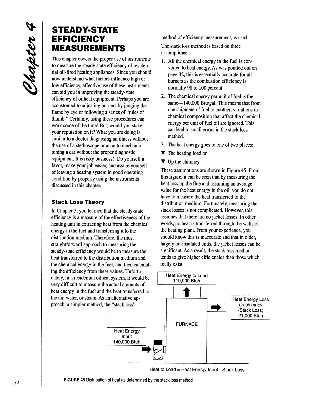
MEASUREMENTS
This chapter covers the proper use of instruments
to measure the steady state efficiency of residen-
tial oil-fired heating appliances. Since you should
now understand what factors influence high or
low efficiency, effective use of these instruments
can aid you in improving the steady-state
efficiency of oilheat equipment. Perhaps you are
accustomed to adjusting burners by judging the
flame by eye or following a series of"rules of
thumb." Certainly, using these procedures can
work some of the time! But, would you stake
your reputation on it? What you are doing is
similar to a doctor diagnosing an illness without
the use of a stethoscope or an auto mechanic
tuning a car without the proper diagnostic
equipment. It is risky business!! Do yourself a
favor, make your job easier, and assure yourself
of leaving a heating system in good operating
condition by properly using the instruments
discussed in this chapter.
Stack Loss Theory
In Chapter 3, you learned that the steady-state
efficiency is a measure of the effectiveness of the
heating unit in extracting heat from the chemical
energy in the fuel and transferring it to the
distribution medium. Therefore, the most
straightforward approach to measuring the
steady-state efficiency would be to measure the
heat transferred to the distribution medium and
the chemical energy in the fuel, and then calculat-
ing the efficiency from these values. Unfortu-
nately, in a residential oilheat system, it would be
very difficult to measure the actual amounts of
heat energy in the fuel and the heat transferred to
the air, water, or steam. As an alternative ap-
proach, a simpler method, the "stack loss"
I Heat Energy
Input
,, 140,000 Btuh
method of efficiency measurement, is used.
The stack loss method is based on three
assumptions:
1. All the chemical energy in the fuel is con-
verted to heat energy. As was pointed out on
page 32, this is essentially accurate for all
burners as the combustion efficiency is
normally 98 to 100 percent.
2. The chemical energy per unit of fuel is the
same_140,000 Bttu'gal. This means that from
one shipment of fuel to another, variations in
chemical composition that affect the chemical
energy per unit of fuel oil are ignored. This
can lead to small errors in the stack loss
method.
3. The heat energy goes to one of two places:
•'The heating load or
•'Up the chimney
These assumptions are shown in Figure 45. From
this figure, it can be seen that by measuring the
heat loss up the flue and assuming an average
value for the heat energy in the oil, you do not
have to measure the heat transferred to the
distribution medium. Fortunately, measuring the
stack losses is not complicated. However, this
assumes that there are no jacket losses. In other
words, no heat is transferred through the walls of
the heating plant. From your experience, you
should know this is inaccurate and that in older,
largely un-insulated units, the jacket losses can be
significant. As a result, the stack loss method
tends to give higher efficiencies than those which
really exist.
Heat Energy to Load
119,000 Btuh
itl
FURNACE
Heat Energy Loss1
up chimney I
(Stack Loss) I
21,000Btuh I
Heat to Load = Heat Energy Input - Stack Loss
FIGURE45 Distributionof heatasdeterminedbythestacklossmethod
32
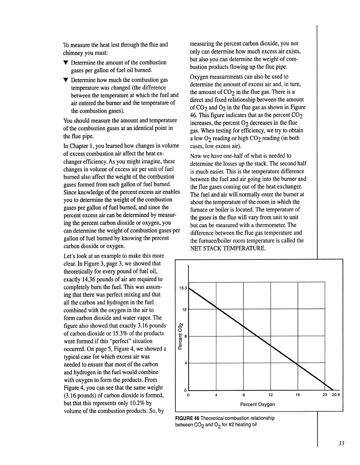
To measure the heat lost through the flue and
chimney you must:
V Determine the amount of the combustion
gases per gallon of fuel oil burned.
V Determine how much the combustion gas
temperature was changed (the difference
between the temperature at which the fuel and
air entered the burner and the temperature of
the combustion gases).
You should measure the amount and temperature
of the combustion gases at an identical point in
the flue pipe.
In Chapter 1, you learned how changes in volume
of excess combustion air affect the heat ex-
changer efficiency. As you might imagine, these
changes in volume of excess air per unit of fuel
burned also affect the weight of the combustion
gases formed from each gallon of fuel burned.
Since knowledge of the percent excess air enables
you to determine the weight of the combustion
gases per gallon of fuel burned, and since the
percent excess air can be determined by measur-
ing the percent carbon dioxide or oxygen, you
can determine the weight of combustion gases per
gallon of fuel burned by knowing the percent
carbon dioxide or oxygen.
Let's look at an example to make this more
clear. In Figure 3, page 3, we showed that
theoretically for every pound of fuel oil,
exactly 14.36 pounds of air are required to
completely burn the fuel. This was assum-
ing that there was perfect mixing and that
all the carbon and hydrogen in the fuel
combined with the oxygen in the air to
form carbon dioxide and water vapor. The
figure also showed that exactly 3.16 pounds
of carbon dioxide or 15.3% of the products
were formed if this "perfect" situation
occurred. On page 5, Figure 4, we showed a
typical case for which excess air was
needed to ensure that most of the carbon
and hydrogen in the fuel would combine
with oxygen to form the products. From
Figure 4, you can see that the same weight
(3.16 pounds) of carbon dioxide is formed,
but that this represents only 10.2% by
volume of the combustion products. So, by
measuring the percent carbon dioxide, you not
only can determine how much excess air exists,
but also you can determine the weight of com-
bustion products flowing up the flue pipe.
Oxygen measurements can also be used to
determine the amount of excess air and, in turn,
the amount of CO 2 in the flue gas. There is a
direct and fixed relationship between the amount
of CO 2 and 02 in the flue gas as shown in Figure
46. This figure indicates that as the percent CO 2
increases, the percent 0 2 decreases in the flue
gas. When testing for efficiency, we try to obtain
a low 0 2 reading or high CO 2 reading (in both
cases, low excess air).
Now we have one-half of what is needed to
determine the losses up the stack. The second half
is much easier. This is the temperature difference
between the fuel and air going into the burner and
the flue gases coming out of the heat exchanger.
The fuel and air will normally enter the burner at
about the temperature of the room in which the
furnace or boiler is located. The temperature of
the gases in the flue will vary from unit to unit
but can be measured with a therrnometer. The
difference between the flue gas temperature and
the fumace/boiler room temperature is called the
NET STACK TEMPERATURE.
15.3
12
o,,I
L)
E8
0
012 16 20
Percent Oxygen
FIGURE 46 Theoretical combustion relationship
between CO2 and 0 2 for #2 heating oil
20,9
33
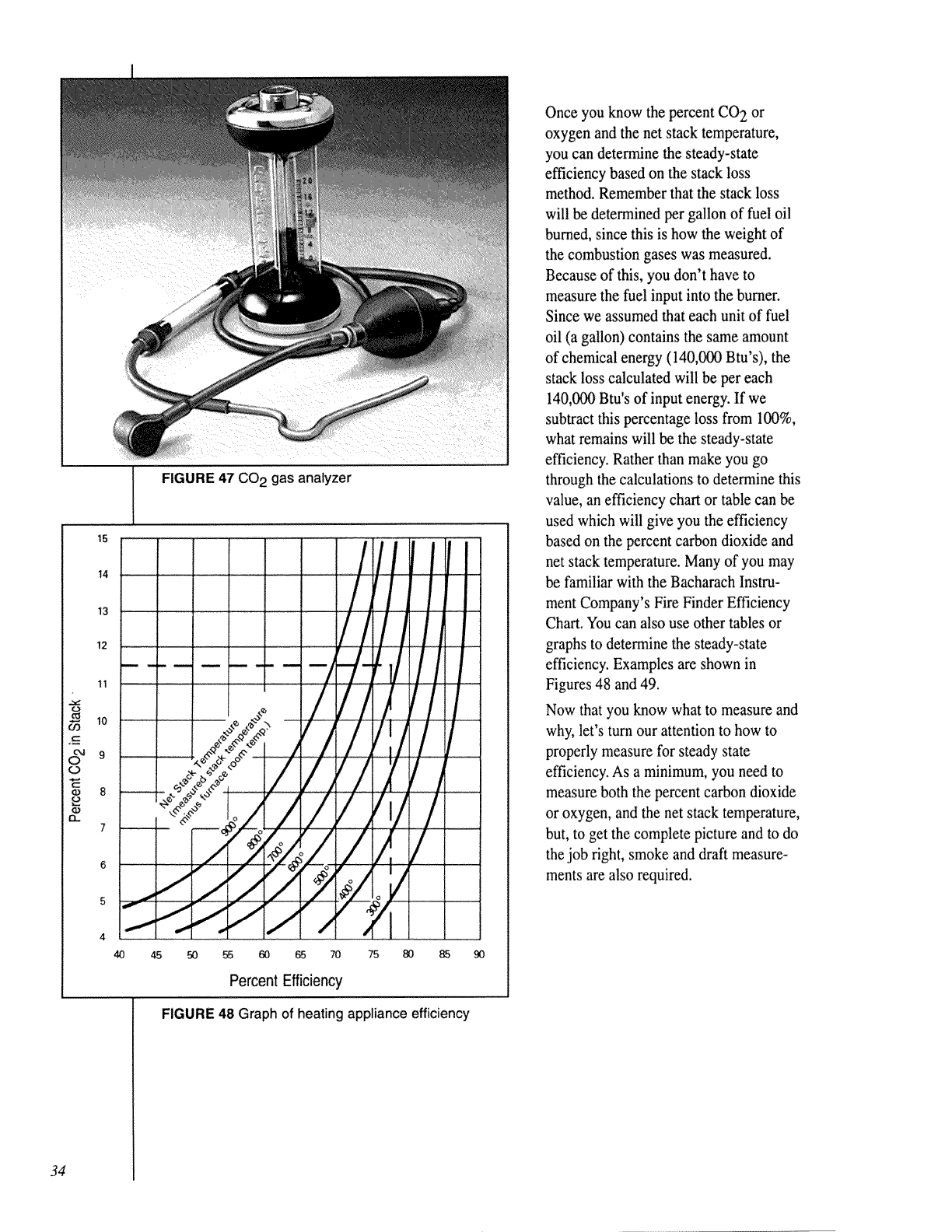
34
FIGURE 47 CO2 gas analyzer
15 /rll
14 ....... /rt
13 J
2
11
° / ,/V
7
°/,4,
€
4 i
40 45 50 55 60 _ 70 75 80 85 90
Percent Efficiency
FIGURE 48 Graph of heating appliance efficiency
Once you know the percent CO 2 or
oxygen and the net stack temperature,
you can determine the steady-state
efficiency based on the stack loss
method. Remember that the stack loss
will be determined per gallon of fuel oil
burned, since this is how the weight of
the combustion gases was measured.
Because of this, you don't have to
measure the fuel input into the burner.
Since we assumed that each unit of fuel
oil (a gallon) contains the same amount
of chemical energy (140,000 Btu's), the
stack loss calculated will be per each
140,0¢_ Btu's of input energy. If we
subtract this percentage loss from 100%,
what remains will be the steady-state
efficiency. Rather than make you go
through the calculations to determine this
value, an efficiency chart or table can be
used which will give you the efficiency
based on the percent carbon dioxide and
net stack temperature. Many of you may
be familiar with the Bacharach Instru-
ment Company's Fire Finder Efficiency
Chart. You can also use other tables or
graphs to determine the steady-state
efficiency. Examples are shown in
Figures 48 and 49.
Now that you know what to measure and
why, let's turn our attention to how to
properly measure for steady state
efficiency. As a minimum, you need to
measure both the percent carbon dioxide
or oxygen, and the net stack temperature,
but, to get the complete picture and to do
the job right, smoke and draft measure-
ments are also required.
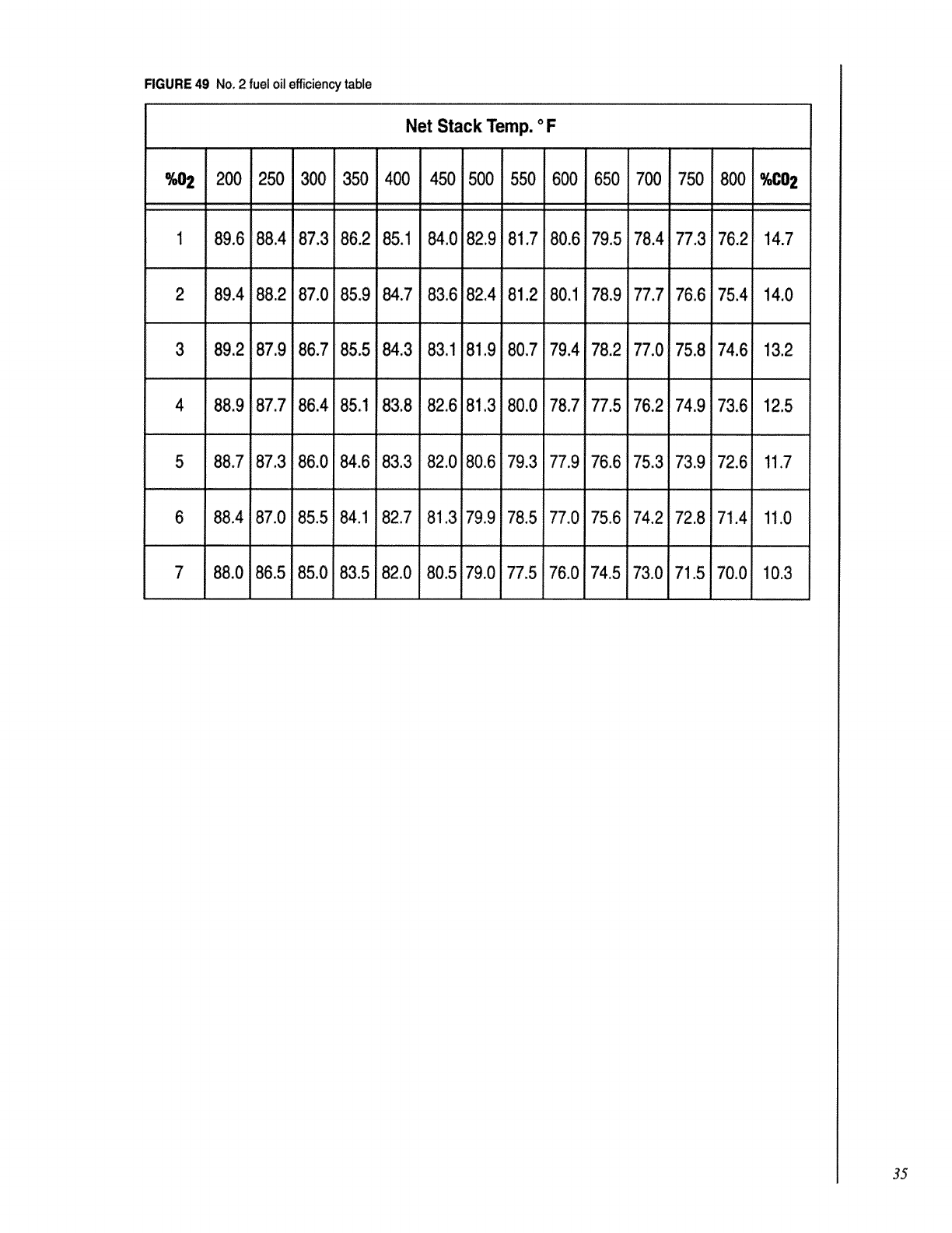
RGURE 49 No. 2 fuel oil efficient-t table
Net Stack Temp. oF
%02 200 250 300 350 400 450 500 550 600 650 700 750 800 _02
1 89.6 88.4 87.3 86.2 85.1 84.0 82.9 81.7 80.6 79.5 78.4 77.3 76.2 14.7
2 89.4 88.2 87.0 85.9 84.7 83.6 82.4 81,2 80.1 78.9 77.7 76.6 75.4 14.0
3 89.2 87.9 86.7 85.5 84.3 83.1 81.9 80.7 79.4 78.2 77.0 75.8 74.6 13.2
4 88.9 87.7 86.4 85.1 83.8 82.6 81.3 80.0 78.7 77.5 76.2 74.9 73.6 12.5
5 88.7 87.3 86.0 84.6 83.3 82.0 80.6 79.3 i77.9 76.6 75.3 73.9 72.6 11.7
6 88.4 87.0 85.5 84.1 82,7 81.3 79.9 78.577.0 75_6 74.2 72.8 71.4 11.0
7 88.0 86.5 85.0 83.5 82.0 80.579.0 77.5 76.0 74.5 73.0 71.5 70.0 10.3
35
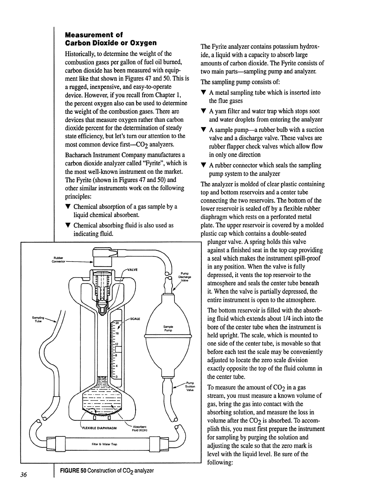
Measurement of
Carbon Dioxide or Oxygen
Historically, to deterroJne the weight of the
combustion gases per gallon of fuel oil burned,
carbon dioxide has been measured with equip-
ment like that shown in Figures 47 and 50. This is
a rugged, inexpensive, and easy-to-operate
device. However, if you recall from Chapter 1,
the percent oxygen also can be used to detenmne
the weight of the combustion gases. There are
devices that measure oxygen rather than carbon
dioxide percent for the determination of steady
state efficiency, but let's turn our attention to the
most common device first---CO 2 analyzers.
Bacharach Instrument Company manufactures a
carbon dioxide analyzer called "Fyrite", which is
the most well-known instpament on the market.
The Fyrite (shown in Figures 47 and 50) and
other similar instruments work on the following
principles:
_' Chemical absorption of a gas sample by a
liquid chemical absorbent.
V Chemical absorbing fluid is also used as
indicating fluid.
I
The Fyrite analyzer contains potassium hydrox-
ide, a liquid with a capacity to absorb large
amounts of carbon dioxide. The Fyrite consists of
two main parts---sampling pump and analyzer.
The sampling pump consists of:
_' A metal sampling tube which is inserted into
the flue gases
•'A yarn filter and water trap which stops soot
and water droplets from entering the analyzer
I' A sample pump--a rubber bulb with a suction
valve and a discharge valve. These valves are
rubber flapper check valves which allow flow
in only one direction
Y A rubber connector which seals the sampling
pump system to the analyzer
The analyzer is molded of clear plastic containing
top and bottom reservoirs and a center tube
connecting the two reservoirs. The bottom of the
lower reservoir is sealed off by a flexible rubber
diaphragm which rests on a perforated metal
plate. The upper reservoir is covered by a molded
plastic cap which contains a double-seated
plunger valve. A spring holds this valve
against a finished seat in the top cap providing
a seal which makes the instrument spill-proof
in any position. When the valve is fully
depressed, it vents the top reservoir to the
atmosphere and seals the center tube beneath
it. When the valve is partially depressed, the
entire instrument is open to the atmosphere.
The bottom reservoir is filled with the absorb-
ing fluid which extends about 1/4 inch into the
bore of the center tube when the instrument is
held upright. The scale, which is mounted to
one side of the center tube, is movable so that
before each test the scale may be conveniently
adjusted to locate the zero scale division
exactly opposite the top of the fluid column in
the center tube.
To measure the amount of CO 2 in a gas
stream, you must measure a known volume of
gas, bring the gas into contact with the
absorbing solution, and measure the loss in
volume after the CO 2 is absorbed. To accom-
plish this, you must first prepare the instrument
for sampling by purging the solution and
adjusting the scale so that the zero mark is
level with the liquid level. Be sure of the
following:
36 FIGURE 50 Construction of CO2 analyzer
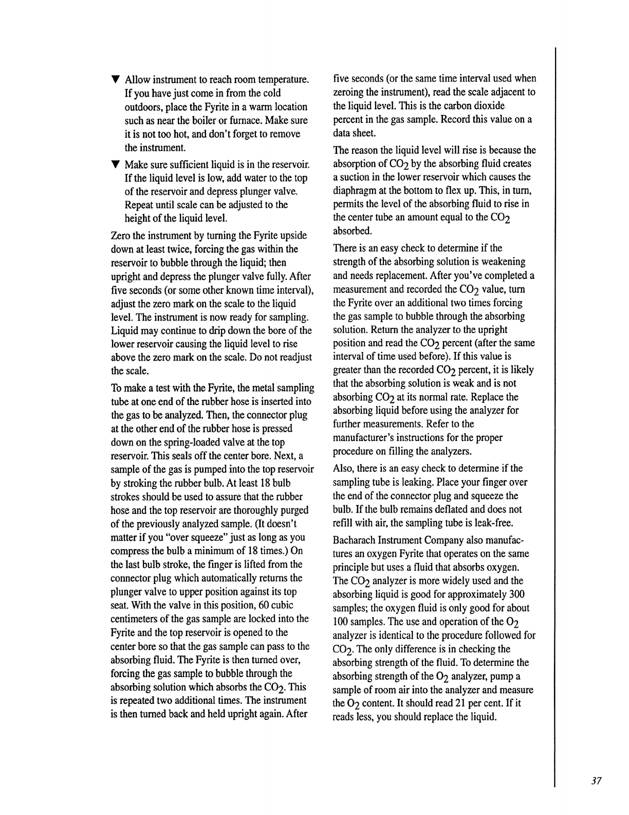
V Allow instrument to reach room temperature.
If you have just come in from the cold
outdoors, place the Fyrite in a warm location
such as near the boiler or furnace. Make sure
it is not too hot, and don't forget to remove
the instrument.
Y Make sure sufficient liquid is in the reservoir.
If the liquid level is low, add water to the top
of the reservoir and depress plunger valve.
Repeat until scale can be adjusted to the
height of the liquid level.
Zero the instrument by turning the Fyrite upside
down at least twice, forcing the gas within the
reservoir to bubble through the liquid; then
upright and depress the plunger valve fully. After
five seconds (or some other known time interval),
adjust the zero mark on the scale to the liquid
level. The instrument is now ready for sampling.
Liquid may continue to drip down the bore of the
lower reservoir causing the liquid level to rise
above the zero mark on the scale. Do not readjust
the scale.
To make a test with the Fyrite, the metal sampling
tube at one end of the rubber hose is inserted into
the gas to be analyzed. Then, the connector plug
at the other end of the rubber hose is pressed
down on the spring-loaded valve at the top
reservoir. This seals off the center bore. Next, a
sample of the gas is pumped into the top reservoir
by stroking the rubber bulb. At least 18 bulb
strokes should be used to assure that the rubber
hose and the top reservoir are thoroughly purged
of the previously analyzed sample. (It doesn't
matter if you "over squeeze" just as long as you
compress the bulb a minimum of 18 times.) On
the last bulb stroke, the finger is lifted from the
connector plug which automatically returns the
plunger valve to upper position against its top
seat. With the valve in this position, 60 cubic
centimeters of the gas sample are locked into the
Fyrite and the top reservoir is opened to the
center bore so that the gas sample can pass to the
absorbing fluid. The Fyrite is then turned over,
forcing the gas sample to bubble through the
absorbing solution which absorbs the CO2. This
is repeated two additional times. The instrument
is then turned back and held upright again. After
five seconds (or the same time interval used when
zeroing the instrumen0, read the scale adjacent to
the liquid level. This is the carbon dioxide
percent in the gas sample. Record this value on a
data sheet.
The reason the liquid level will rise is because the
absorption of CO 2 by the absorbing fluid creates
a suction in the lower reservoir which causes the
diaphragm at the bottom to flex up. This, in turn,
pe_ts the level of the absorbing fluid to rise in
the center tube an amount equal to the CO 2
absorbed.
There is an easy check to determine if the
strength of the absorbing solution is weakening
and needs replacement. After you've completed a
measurement and recorded the CO 2 value, turn
the Fyrite over an additional two times forcing
the gas sample to bubble through the absorbing
solution. Return the analyzer to the upright
position and read the CO 2 percent (after the same
interval of time used before). If this value is
greater than the recorded CO 2 percent, it is likely
that the absorbing solution is weak and is not
absorbing CO 2 at its normal rate. Replace the
absorbing liquid before using the analyzer for
further measurements. Refer to the
manufacturer's instrnctions for the proper
procedure on filling the analyzers.
Also, there is an easy check to determine if the
sampling tube is leaking. Place your finger over
the end of the connector plug and squeeze the
bulb. If the bulb remains deflated and does not
refill with air, the sampling tube is leak-free.
Bacharach Instrument Company also manufac-
tures an oxygen Fyrite that operates on the same
principle but uses a fluid that absorbs oxygen.
The CO2 analyzer is more widely used and the
absorbing liquid is good for approximately 300
samples; the oxygen fluid is only good for about
100 samples. The use and operation of the 0 2
analyzer is identical to the procedure followed for
CO2. The only difference is in checking the
absorbing strength of the fluid. To determine the
absorbing strength of the 0 2 analyzer, pump a
sample of room air into the analyzer and measure
the 0 2 content. It should read 21 per cent. If it
reads less, you should replace the liquid.
37
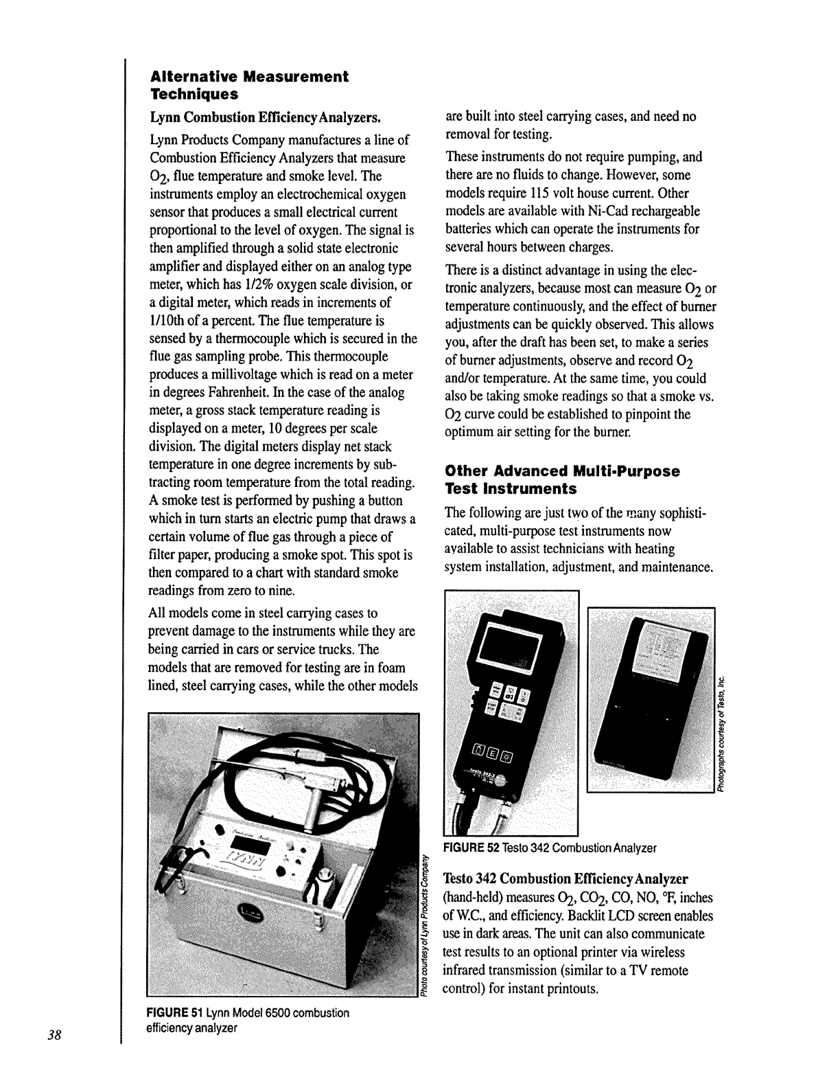
Alternative Measurement
Techniques
Lynn Combustion Efficiency Analyzers.
Lynn Products Company manufactures a line of
Combustion Efficiency Analyzers that measure
0 2, flue temperature and smoke level. The
instruments employ an electrochemical oxygen
sensor that produces a small electrical current
proportional to the level of oxygen. The signal is
then amplified through a solid state electronic
amplifier and displayed either on an analog type
meter, which has I/2% oxygen scale division, or
a digital meter, which reads in increments of
1/10th of a percent. The flue temperature is
sensed by a thermocouple which is secured in the
flue gas sampling probe. This thermocouple
produces a millivoltage which is read on a meter
in degrees Fahrenheit. In the case of the analog
meter, a gross stack temperature reading is
displayed on a meter, 10 degrees per scale
division. The digital meters display net stack
temperature in one degree increments by sub-
tracting room temperature from the total reading.
A smoke test is performed by pushing a button
which in turn starts an electric pump that draws a
certain volume of flue gas through a piece of
filter paper, producing a smoke spot. This spot is
then compared to a chart with standard smoke
readings from zero to nine.
All models come in steel carrying cases to
prevent damage to the instruments while they are
being carded in cars or service trucks. The
models that are removed for testing are in foam
lined, steel carrying cases, while the other models
are built into steel carrying cases, and need no
removal for testing.
These instoaments do not require pumping, and
there are no fluids to change. However, some
models require 115 volt house current. Other
models are available with Ni-Cad rechargeable
batteries which can operate the instruments for
several hours between charges.
There is a distinct advantage in using the elec-
tronic analyzers, because most can measure 0 2 or
temperature continuously, and the effect of burner
adjustments can be quickly observed. This allows
you, after the draft has been set, to make a series
of burner adjustments, observe and record 0 2
and/or temperature. At the same time, you could
also be taking smoke readings so that a smoke vs.
O2 curve could be established to pinpoint the
optimum air setting for the burner.
Other Advanced Multi-Purpose
Test Instruments
The following are just two of the many sophisti-
cated, multi-purpose test instruments now
available to assist technicians with heating
system installation, adjustment, and maintenance.
FIGURE 52 Testo342 Combustion Analyzer
Testo 342 Combustion EfficiencyAnalyzer
(hand-held) measures 02, CO2, CO, NO, °F,inches
of'_:C., and efficiency. Backlit LCD screen enables
use in darkareas. The unit can also communicate
test results to an optional printervia wireless
infraredtransmission (similar to aTV remote
control) for instant printouts.
38
FIGURE51LynnModel6500combustion
efficiencyanalyzer
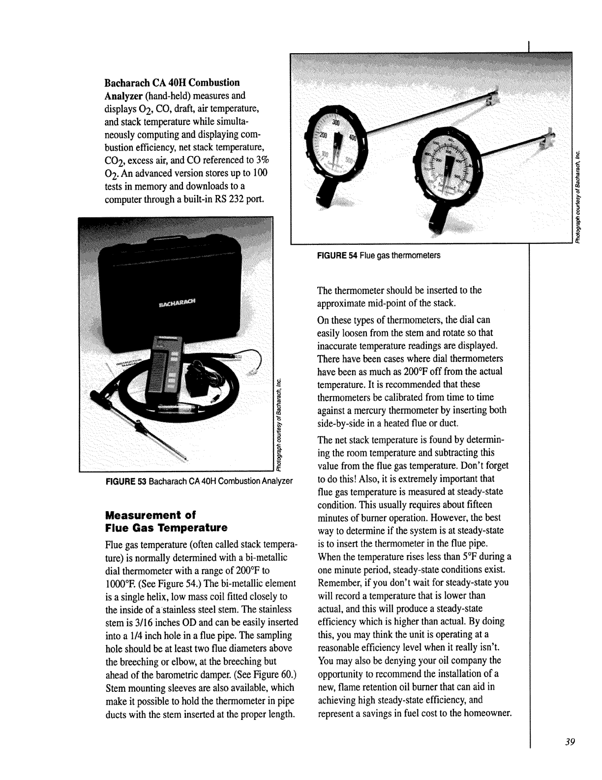
Bacharach CA 40H Combustion
Analyzer (hand-held) measures and
displays 0 2, CO, draft, air temperature,
and stack temperature while simulta-
neously computing and displaying com-
bustion efficiency, net stack temperature,
CO 2, excess air, and CO referenced to 3%
0 2. An advanced version stores up to 100
tests in merr_gry and downloads to a
computer through a built-in RS 232 port.
RGURE 53 Bacharach CA40H CombustionAnalyzer
Measurement of
Flue Gas Temperature
Flue gas temperature (often called stack tempera-
ture) is normally determined with a bi-metallic
dial thermometer with a range of 200°F to
1000°E (See Figure 54.) The bi-metallic element
is a single helix, low mass coil fitted closely to
the inside of astainless steel stem. The stainless
stem is 3/16 inches OD and can be easily inserted
into a 1/4 inch hole in a flue pipe. The sampling
hole should be at least two flue diameters above
the breeching or elbow, at the breeching but
ahead of the barometric damper. (See Figure 60.)
Stem mounting sleeves are also available, which
make it possible to hold the thermometer in pipe
ducts with the stem inserted at the proper length.
RGURE54Fluegasthermometers
The thermometer should be inserted to the
approximate mid-point of the stack.
On these types of thermometers, the dial can
easily loosen from the stem and rotate so that
inaccurate temperature readings are displayed.
There have been cases where dial thermometers
have been as much as 200°F off from the actual
temperature, It is recommended that these
thermometers be calibrated from time to time
against a mercury thermometer by inserting both
side-by-side in a heated flue or duct.
The net stack temperature is found by determin-
ing the room temperature and subtracting this
value from the flue gas temperature. Don't forget
to do this! Also, it is extremely important that
flue gas temperature is measured at steady-state
condition. This usually requires about fifteen
minutes of burner operation. However, the best
way to determine if the system is at steady-state
is to insert the thermometer in the flue pipe.
When the temperature rises less than 5°F during a
one minute period, steady-state conditions exist.
Remember, if you don't wait for steady-state you
will record a temperature that is lower than
actual, and this will produce a steady-state
efficiency which is higher than actual. By doing
this, you may think the unit is operating at a
reasonable efficiency level when it really isn't.
You may also be denying your oil company the
opportunity to recommend the installation of a
new, flame retention oil burner that can aid in
achieving high steady-state efficiency, and
represent a savings in fuel cost to the homeowner.
39
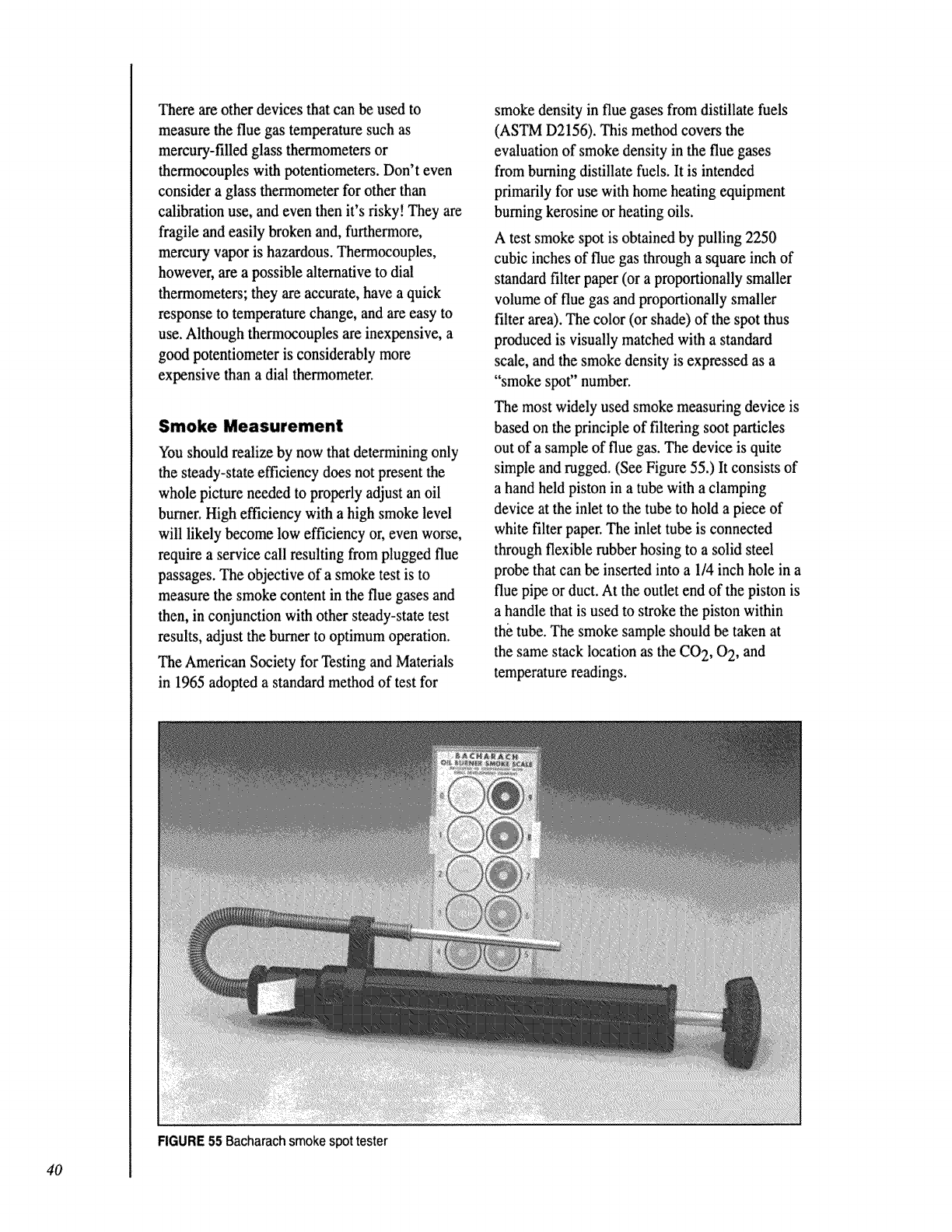
There are other devices that cart be used to
measure the flue gas temperature such as
mercury-filled glass thermometers or
thermocouples with potentiometers. Don't even
consider a glass thermometer for other than
calibration use, and even then it's risky! They are
fragile and easily broken and, furthermore,
mercury vapor is hazardous. Thermocouples,
however, are a possible alternative to dial
thermometers; they are accurate, have a quick
response to temperature change, and are easy to
use. Although thermocouples are inexpensive, a
good potentiometer is considerably more
expensive than a dial thermometer.
Smoke Measurement
You should realize by now that determining only
the steady-state efficiency does not present the
whole picture needed to properly adjust an oil
burner. High efficiency with a high smoke level
will likely become low efficiency or, even worse,
require a service call resulting from plugged flue
passages. The objective of a smoke test is to
measure the smoke content in the flue gases and
then, in conjunction with other steady-state test
results, adjust the burner to optimum operation.
The American Society for Testing and Materials
in 1965 adopted a standard method of test for
FIGURE 55 Bacharachsmoke spot tester
smoke density in flue gases from distillate fuels
(ASTM D2156). This method covers the
evaluation of smoke density in the flue gases
from burning distillate fuels, it is intended
primarily for use with home heating equipment
burning kerosine or heating oils.
A test smoke spot is obtained by pulling 2250
cubic inches of flue gas through a square inch of
standard filter paper (or a proportionally smaller
volume of flue gas and proportionally smaller
filter area). The color (or shade) of the spot thus
produced is visually matched with a standard
scale, and the smoke density is expressed as a
"smoke spot" number.
The most widely used smoke measuring device is
based on the principle of filtering soot particles
out of a sample of flue gas. The device is quite
simple and nagged. (See Figure 55.) It consists of
a hand held piston in a tube with a clamping
device at the inlet to the tube to hold a piece of
white filter paper. The inlet tube is connected
through flexible rubber hosing to a solid steel
probe that can be inserted into a 1/4 inch hole in a
flue pipe or duct. At the outlet end of the piston is
a handle that is used to stroke the piston within
the tube. The smoke sample should be taken at
the same stack location as the CO 2, 0 2, and
temperature readings.
40
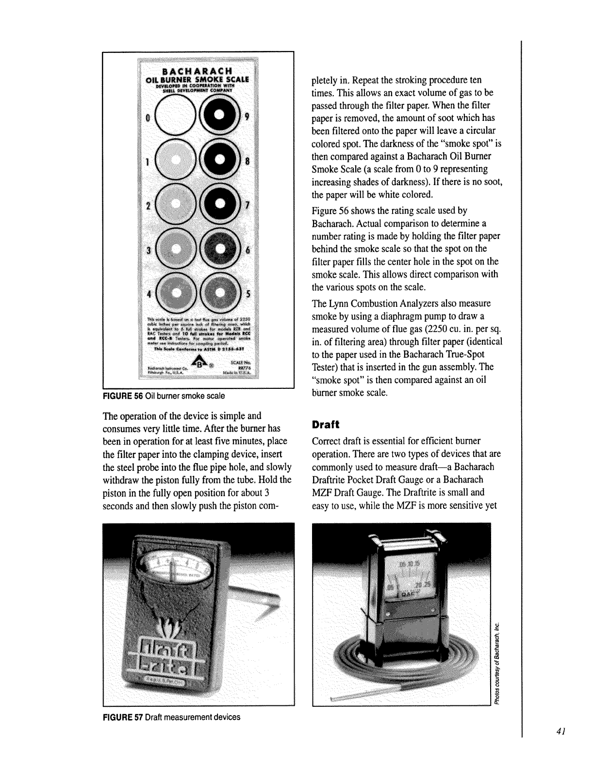
FIGURE 56 Oil burnersmokescale
The operation of the device is simple and
consumes very little time. After fineburner has
been in operation for at least five minutes, place
the filter paper into the clamping device, insert
the steel probe into the flue pipe hole, and slowly
withdraw the piston fully from the tube, Hold the
piston in the fully open position for about 3
seconds and then slowly push the piston corn-
pletely in. Repeat the stroking procedure ten
times. This allows an exact volume of gas to be
passed through the filter paper. When the filter
paper is removed, the amount of soot which has
been filtered onto the paper will leave a circular
colored spot. The darkness of the "smoke spot" is
then compared against a Bacharach Oil Bumer
Smoke Scale (a scale from 0 to 9 representing
increasing shades of darkness). If there is no soot,
the paper will be white colored.
Figure 56 shows the rating scale used by
Bacharach. Actual comparison to determine a
number rating is made by holding the filter paper
behind the smoke scale so that the spot on the
filter paper fills the center hole in the spot on the
smoke scale. This allows direct comparison with
the various spots on the scale.
The Lynn Combustion Analyzers also measure
smoke by using a diaphragm pump to draw a
measured volume of flue gas (2250 cu. in. per sq,
in. of filtering area) through filter paper (identical
to the paper used in the Bacharach True-Spot
Tester) that is inserted in the gun assembly. The
"smoke spot" is then compared against an oil
bumer smoke scale.
Draft
Correct draft is essential for efficient burner
operation. There are two types of devices that are
commonly used to measure draft--a Bacharach
Draftrite Pocket Draft Gauge or a Bacharach
MZF Draft Gauge. The Draftrite is small and
easy to use, while the MZF is more sensitive yet
FIGURE 57 Draft measurement devices
41
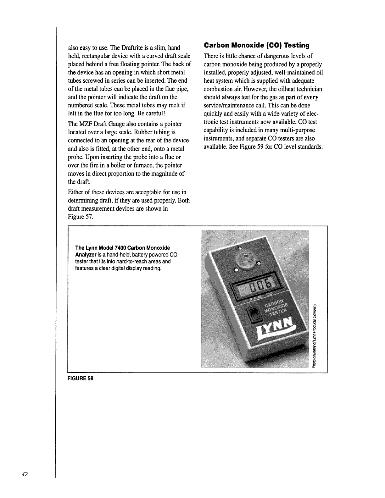
also easy to use. The Draftrite is a slim, hand
held, rectangular device with a curved draft scale
placed behind a free floating pointer. The back of
the device has an opening in which short metal
tubes screwed in series can be inserted. The end
of the metal tubes can be placed in the flue pipe,
and the pointer will indicate the draft on the
numbered scale. These metal tubes may melt if
left in the flue for too long. Be careful!
The MZF Draft Gauge also contains a pointer
located over a large scale. Rubber tubing is
connected to an opening at the rear of the device
and also is fitted, at the other end, onto a metal
probe. Upon inserting the probe into a flue or
over the fire in a boiler or furnace, the pointer
moves in direct proportion to the magnitude of
the draft.
Either of these devices are acceptable for use in
determining draft, if they are used properly. Both
draft measurement devices are shown in
Figure 57.
Carbon Monoxide (CO) Testing
There is little chance of dangerous levels of
carbon monoxide being produced by a properly
installed, properly adjusted, well-maintained oil
heat system which is supplied with adequate
combustion air. However, the oilheat technician
should always test for the gas as part of every
service/maintenance call. This can be done
quickly and easily with a wide variety of elec-
tronic test instruments now available. CO test
capability is included in many multi-purpose
instruments, and separate CO testers are also
available. See Figure 59 for CO level standards.
The Lynn Model 7400 Carbon Monoxide
Analyzer isa hand-held,batterypowered CO
testerthat fitsinto hard-to-reachareas and
features a cleardigitaldisplayreading.
FIGURE 58
42
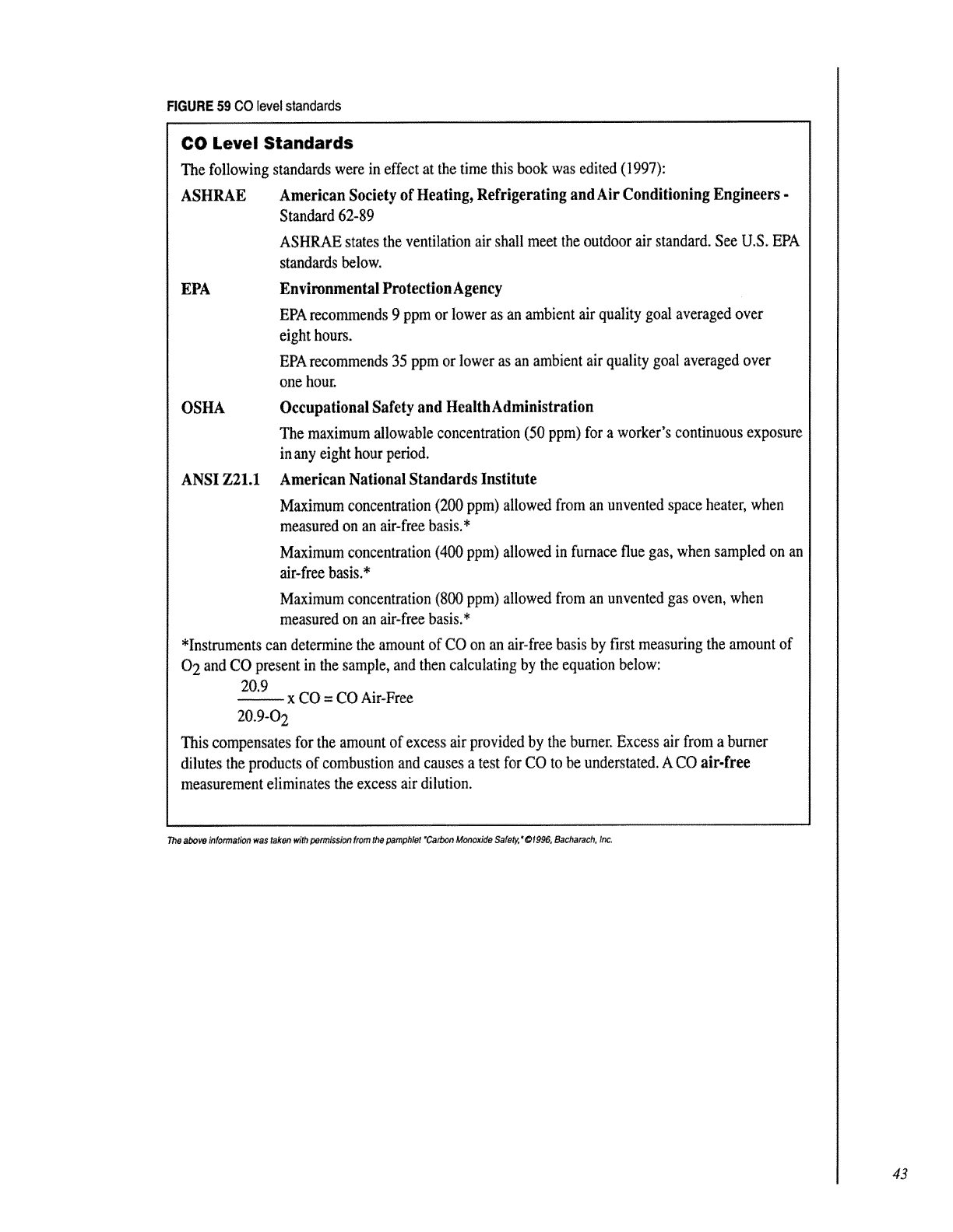
FIGURE59COlevelstandards
CO Level Standards
The following standards were in effect at the time this book was edited (1997):
ASHRAE American Society of Heating, Refrigerating and Air Conditioning Engineers -
Standard 62-89
ASHP_E states the ventilation air shall meet the outdoor air standard. See U.S. EPA
standards below.
EPA Environmental Protection Agency
EPA recommends 9 ppm or lower as an ambient air quality goal averaged over
eight hours.
EPA recommends 35 ppm or lower as an ambient air quality goal averaged over
one hour.
OSHA
ANSI Z21.1
Occupational Safety and HealthAdministration
The maximum allowable concentration (50 ppm) for aworker's continuous exposure
in any eight hour period.
American National Standards Institute
Maximum concentration (200 ppm) allowed from an unvented space heater, when
measured on an air-free basis.*
Maximum concentration (400 ppm) allowed in furnace flue gas, when sampled on an
air-free basis.*
Maximum concentration (800 ppm) allowed from an unvented gas oven, when
measured on an air-free basis.*
*Instruments can determine the amount of CO on an air-free basis by first measuring the amount of
0 2 and CO present in the sample, and then calculating by the equation below:
20.9 x CO = CO Air-Free
20.9-0 2
This compensates for the amount of excess air provided by the burner. Excess air from a burner
dilutes the products of combustion and causes a test for CO to be understated. A CO air-free
measurement eliminates the excess air dilution.
The above information was taken with permission from the pamph/et "Carbon Monoxide Safety," @1996, Bacharach, Inc.
43
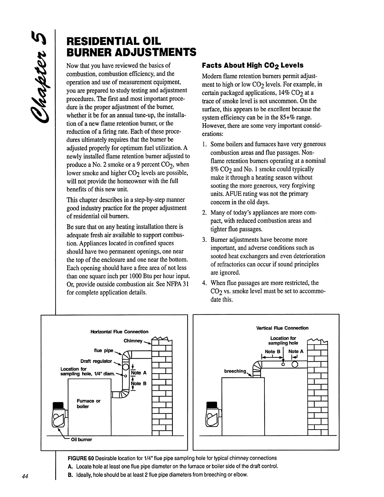
RESIDENTIAL OIL
BURNER ADJUSTMENTS
Now that you have reviewed the basics of
combustion, combustion efficiency, and the
operation and use of measurement equipment,
you are prepared to study testing and adjustment
procedures. The first and most important proce-
dure is the proper adjustment of the burner,
whether it be for an annual tune-up, the installa-
tion of a new flame retention burner, or the
reduction of a firing rate. Each of these proce-
dures ultimately requires that the burner be
adjusted properly for optimum fuel utilization. A
newly installed flame retention burner adjusted to
produce a No. 2 smoke or a 9 percent CO 2, when
lower smoke and higher CO2 levels are possible,
will not provide the homeowner with the full
benefits of this new unit.
This chapter describes in a step-by-step manner
good industry practice for the proper adjustment
of residential oil burners.
Be sure that on any heating installation there is
adequate fresh air available to support combus-
tion. Appliances located in confined spaces
should have two permanent openings, one near
the top of the enclosure and one near the bottom.
Each opening should have a free area of not less
than one square inch per 1000 Btu per hour input.
Or, provide outside combustion air. See NFPA 31
for complete application details.
Facts About High CO 2 Levels
Modem flame retention burners permit adjust-
ment to high or low CO 2 levels. For example, in
ce_n packaged applications, 14% CO 2 at a
trace of smoke level is not uncommon. On the
surface, this appears to be excellent because the
system efficiency can be in the 85+% range.
However, there are some very important consid-
erations:
1. Some boilers and furnaces have very generous
combustion areas and flue passages. Non-
flame retention burners operating at a nominal
8% CO 2 and No. 1 smoke could typically
make it through a heating season without
sooting the more generous, very forgiving
units. AFUE rating was not the primary
concern in the old days.
2. Many of today's appliances are more com-
pact, with reduced combustion areas and
tighter flue passages.
3. Burner adjustments have become more
important, and adverse conditions such as
sooted heat exchangers and even deterioration
of refractories can occur if sound principles
are ignored.
4. When flue passages are more restricted, the
CO 2 vs. smoke level must be set to accommo-
date this.
44
Hodzor_l Flue Con_on
flue pipe
Draft regulator ,,_,_
Location for
sampling hole, 1/4"diam. "-,
[]
Furnace or
boiler
Chimney
........... -r
Oil burner
.!
...l....p..
..-t....p...
=-
Vertical Rue Connection
Location for
sampling hole
breeching._! 60
| .
_=
E
FIGURE 60 Desirable location for 114=flue pipesampling hole fortypical chimneyconnections
A. Locate hole at least one flue pipe diameter on the furnace or boiler side of the draft control.
B. ideally, hole should be at least 2 flue pipe diameters from breeching or elbow.
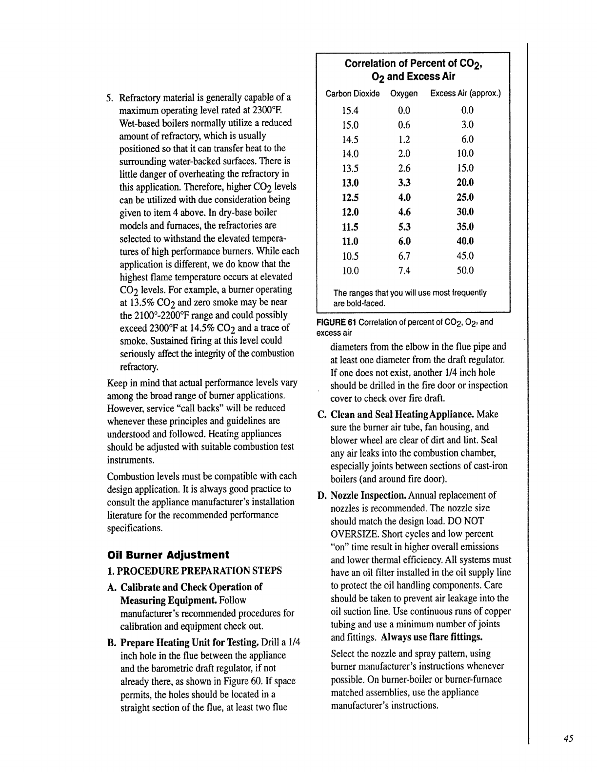
5. Refractor.,, material is generally capable of a
maximum operating level rated at 2300°E
Wet-based boilers normally utilize a reduced
amount of refractory, which is usually
positioned so that it can transfer heat to the
surrounding water-backed surfaces. There is
little danger of overheating the refractory in
this application. Therefore, higher CO 2 levels
can be utilized with due consideration being
given to item 4 above. In dry-base boiler
models and furnaces, the refractories are
selected to withstand the elevated tempera-
tures of high performance burners. While each
application is different, we do know that the
highest flame temperature occurs at elevated
CO 2 levels. For example, a burner operating
at 13.5% CO 2 and zero smoke may be near
the 2100°-2200°F range and could possibly
exceed 2300°F at 14.5% CO 2 and a trace of
smoke. Sustained firing at this level could
seriously affect the integrity of the combustion
refractory.
Keep in mind that actual performance levels vary
among finebroad range of burner applications.
However, service "call backs" will be reduced
whenever these principles and guidelines are
understood and followed. Heating appliances
should be adjusted with suitable combustion test
instruments.
Combustion levels must be compatible with each
design application. It is always good practice to
consult the appliance manufacturer's installation
literature for the recommended performance
specifications.
Oil Burner Adjustment
1. PROCEDURE PREPARATION STEPS
A. Calibrate and Check Operation of
Measuring Equipment. Follow
manufacturer's recommended procedures for
calibration and equipment check out.
B. Prepare Heating Unit for Testing. Drill a I/4
inch hole in the flue between the appliance
and the barometric draft regulator, if not
already there, as shown in Figure 60. If space
permits, the holes should be located in a
straight section of the flue, at least two flue
Correlation of Percent of CO 2,
0 2 and Excess Air
Carbon Dioxide Oxygen Excess Air (approx.)
I5.4 0.0 0.0
15.0 0.6 3.0
14.5 1.2 6.0
14.0 2.0 10.0
13.5 2.6 15.0
13.0 3.3 20.0
12.5 4.0 25.0
12.0 4.6 30.0
11.5 5.3 35.0
11.0 6.0 40.0
10.5 6.7 45.0
10.0 7.4 50.0
The ranges thatyou willuse most frequently
are bold-faced.
FIGURE 61 Correlation of percent of CO2, 02, and
excess air
diameters from the elbow in the flue pipe and
at least one diameter from the draft regulator.
If one does not exist, another 1/4 inch hole
should be drilled in the fire door or inspection
cover to check over fire draft.
Do
Clean and Seal HeatingAppliance. Make
sure the burner air tube, fan housing, and
blower wheel are clear of dirt and lint. Seal
any air leaks into the combustion chamber,
especially joints between sections of cast-iron
boilers (and around fire door).
Nozzle Inspection. Annual replacement of
nozzles is recommended. The nozzle size
should match the design load. DO NOT
OVERSIZE. Short cycles and low percent
"on" time result in higher overall emissions
and lower thermal efficiency. All systems must
have an oil filter installed in the oil supply line
to protect the oil handling components. Care
should be taken to prevent air leakage into the
oil suction line. Use continuous runs of copper
tubing and use a minimum number of joints
and fittings. Always use flare fittings.
Select the nozzle and spray pattern, using
burner manufacturer's instructions whenever
possible. On burner-boiler or burner-furnace
matched assemblies, use the appliance
manufacturer's instructions.
45
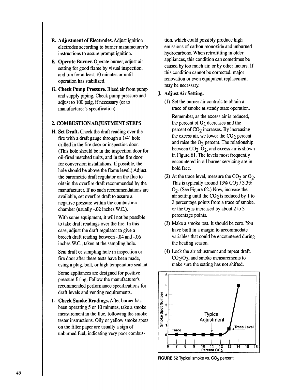
E. Adjustment of Electrodes. Adjust ignition
electrodes according to burner manufacturer's
instructions to assure prompt ignition.
F. Operate Burner. Operate burner, adjust air
setting for good flame by visual inspection,
and run for at least 10 minutes or until
operation has stabilized.
G. Check Pump Pressure. Bleed air from pump
and supply piping. Check pump pressure and
adjust to I00 psig, if necessary (or to
manufacturer's specification).
2. COMBUSTION ADJUSTMENT STEPS
H. Set Draft. Check the draft reading over the
fire with a draft gauge through a1/4" hole
drilled in the fire door or inspection door.
(This hole should be in the inspection door for
oil-fired matched units, and in the fire door
for conversion installations. If possible, the
hole should be above the flame level.) Adjust
the barometric draft regulator on the flue to
obtain the overfire draft recommended by the
manufacturer. If no such recommendations are
available, set overfire draft to assure a
negative pressure within the combustion
chamber (usually -.02 inches W.C.).
With some equipment, it will not be possible
to take draft readings over the fire. In this
case, adjust the draft regulator to give a
breech draft reading between -.04 and -.06
inches W:C., taken at the sampling hole.
Seal draft or sampling hole in inspection or
fire door after these tests have been made,
using a plug, bolt, or high temperature sealant.
Some appliances are designed for positive
pressure firing. Follow the manufacturer's
recommended performance specifications for
draft levels and venting requirements.
I. Check Smoke Readings. After burner has
teen operating 5 or 10 minutes, take a smoke
measurement in the flue, following the smoke
tester instructions. Oily or yellow smoke spots
on the filter paper are usually a sign of
unburned fuel, indicating very poor combus-
J!
tion, which could possibly produce high
emissions of carbon monoxide and unburned
hydrocarbons. When retrofitting in older
appliances, this condition can sometimes be
caused by too much air, or by other factors, if
this condition cannot be corrected, major
renovation or even equipment replacement
may be necessary.
Adjust Air Setting.
(1) Set the burner air controls to obtain a
trace of smoke at steady state operation.
Remember, as the excess air is reduced,
the percent of 0 2 decreases and the
percent of CO 2 increases. By increasing
the excess air, we lower the CO 2 percent
and raise the 0 2 percent. The relationship
between CO 2, 0 2, and excess air is shown
in Figure 61. The levels most frequently
encountered in oil burner servicing are in
bold face.
(2) At the trace level, measure the CO 2 or 0 2.
This is typically around 13% CO 2 /3.3%
02 . (See Figure 62.) Now, increase the
air setting until the CO 2 is reduced by 1 to
2 percentage points from a trace of smoke,
or the 0 2 is increased by about 2 to 3
percentage points.
(3) Make a smoke test. It should be zero. You
have built in a margin to accommodate
v_ables that could be encountered during
the heating season.
(4) Lock the air adjustment and repeat draft,
CO2/O 2, and smoke measurements to
make sure the setting has not shifted.
16 f 1
Typioa,
I_ Adjustment[ I
RGURE 62 Typicalsmoke vs. CO 2 percent
46
RECORDING OF READINGS
Now that you've performed your adjustment,
record the readings on a form similar to that
shown in Figure 63. This will be left to inform
the homeowner of the measurements you made.
This type of information is important for
homeowners to receive. It improves your image
and indicates to the homeowner that you and
your company are responsible and thorough.
Remember, horneowners are being told that
measurements are an essential part of proper
burner/furnace/boiler adjustment. Fill the form
out and leave it with the homeowner! If the test
results indicate poor or fair efficiency, recom-
mend to the homeowner that he or she contact
your oil company representative for a complete
evaluation and/or an energy conservation
recommendation.
THE ANNUAL CLEAN-UP
We strongly recommend that the following
procedures be performed each year in advance of
the heating season:
A. Fire Test the Unit
Does it function normally? Ask the
homeowner questions and listen to the
answers. If there are troubles with the unit,
you may need to make repairs or run a
combustion test.
B. Clean the Flue
Turn off the power. Put on a respirator mask
and leave the vacuum running with the
snorkel inside the area being cleaned to catch
airborne particles. Remove the flue pipe and
clean it thoroughly. Check the chimney for
blockage. Check the barometric regulator.
C. Clean the Secondary Heat Exchanger
Remove the flue collector box. Remove
baffles and scrub passages with a flue brush.
Shoot for "day one" condition to boost
efficiency. Look for cracks, etc. Use any
auxiliary clean-out ports.
D. Clean the Combustion Area
E.
F.
Older units may have a view or fire door for
access to the combustion area. You may have
to remove the burner and front plate to reach
the primary heating surfaces. Note the
refractory condition and repair or replace as
necessary. Be careful not to damage the
refractory material when cleaning ceramic
fiber chambers. Use a soot snorkel or make
one from 3/4" air conditioning or garden hose
with duct tape wrapping for a bushing.
Replace, Seal and Fasten
Put everything back in place, sealing leaks or
cracks with furnace cement and using sheet
metal screws on stack joints.
Furnace or Boiler?
Furnace: Open the blower compartment to
check filters, oil the motor and blower shaft
beatings, check V-belt tension and pulley
alignment. Brush lint and dirt from blower
wheel. Check blower mountings for noisy
operation.
Boiler: Oil circulator motor and bearing
assembly. Check circulator coupling. Drain
expansion tank if needed. 47
G. Service the Burner
2.
Make sure the power is off.
Remove the pump strainer cover and clean
strainer. Replace cover gasket. Secure
cover.
3. Replace oil filter element, leaving the
canister clean and tight. Sludge or water
means the _'ak needs to be checked for the
cause. Assure oil lines are clean, straight
and all fittings are leak-free. Use flare
fittings; never compression fittings.
4. Remove the firing assembly. Clean internal
tubing. Check electrode porcelains for
cracks. Replace nozzle with specified type.
Do not over-tighten. Set electrodes to
manufacturer's specs.
5. Clean any dirt from combustion head slots
and holes. Inspect for damage and suitable
firing range. Replace firing assembly.
6. If the burner has not been removed, check
the condition of the combustion head using
a flame mirror and flashlight. It should be
recessed 1/4" from the inside chamber
wall, but check manufacturer's specs to be
sure. Also check nozzle concentricity.
7. Clean transformer bushings and springs as
well as the cad cell surface. Check bracket
alignment for good flame sighting.
8. Use a small brush and vacuum cleaner
snorkel to clean the air inlets and blower
vanes to "like new" condition.
9_ Oil the burner motor with 3-4 drops of
SAE 20 or 30 oil. Some motors are
permanently lubricated, and should not be
oiled.
10. Check to see that all wiring connections
are secure and insulation is not broken or
cut.
11. Time the safety lock-out while you bleed
all air from the pump. Test pump pressure
and set at 100 psig or to manufacturer's
specs. Check the cut-off to see that
pressure drops to approximately 80% of
operating level.
12. Restore power. Turn finebumer ON. "view
the flame for uniformity and concentricity
with no impingement.
H. CombustionTesting
1. Refer back to combustion adjustment steps
on page 46.
2. Take a gross stack temperature reading.
Subtract room ambient temperature and
use an efficiency chart to determine
steady-state readings with the net stack
temperature and CO 2 or 0 2 levels.
3. Cycle the burner to assure prompt ignition
and smooth operation. Repeat cycling,
purging air bubbles from nozzle adapter
until cut-off is clean with no after-squirt.
I. Check Safety andAuxiliary Controls
Cut power to the blower or circulator motor
and cycle the burner until safety limits shut
the burner off. Check automatic feed valves,
low water cut-off and pressure relief valves.
Flush low water cut-off valves. Use sight
glass on steam units to check water level.
Determine that limit controls will shut down
the burner if operating controls fail. Be sure
the installation meets current codes. Cycle the
burner and observe one complete operation
sequence.
J. Clean theArea
K. Reset Thermostat and Operating or Limit
Control Temperature Settings
L. Record your Findings
Make a written record of anything unusual or
needing service. Give a copy to the customer and
your service manager. Arrange for follow-up.
48
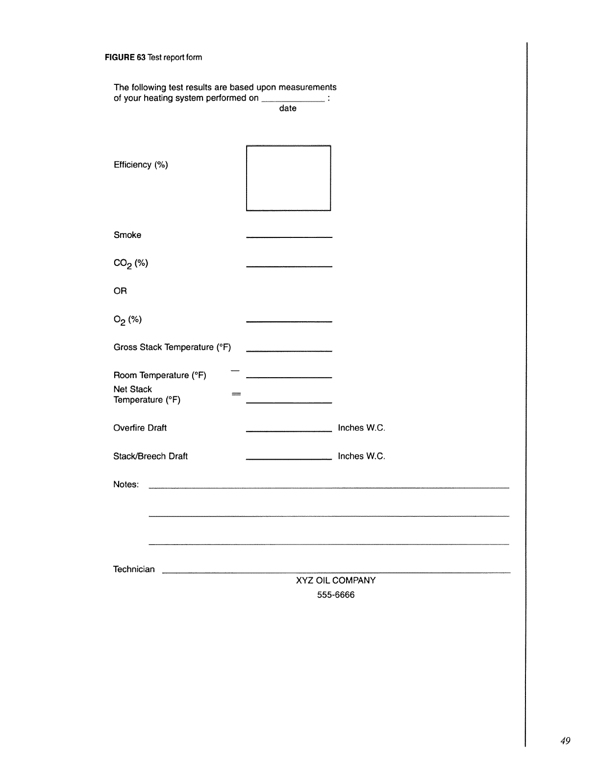
FIGURE 63 Testreportform
The following test results are based upon measurements
of your heating system performed on date
Efficiency (%)
Smoke
i
CO2 (%)
OR
0 2 (%)
Gross Stack Temperature (°F)
Room Temperature (°F)
Net Stack
Temperature (°F)
Overfire Draft Inches W.C,
Stack/Breech Draft Inches W.C.
Notes:
Technician
XYZ OIL COMPANY
555-6666
49
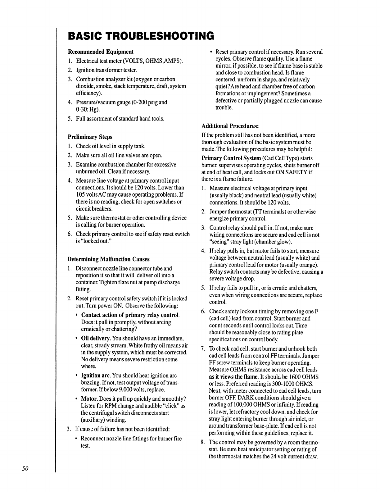
BASIC TROUBLESHOOTING
Recommended Equipment
1. Electrical test meter (VOLTS, OHMS,AMPS).
2. Ignition transformer tester,
3. Combustion analyzerkit (oxygen orcarbon
dioxide, smoke, stack temperature, draft, system
efficiency).
4. Pressure/vacuum gauge (0-200 psig and
0-30: Hg).
5. Full assortment of standard hand tools.
Preliminary Steps
1. Check oil level in supply tank.
2. Make sure all oil line valves are open.
3. Examine combustion chamber for excessive
unburned oil. Clean if necessary.
4. Measure line voltage at primary control input
connections. It should be 120 volts. I_wer than
105 voltsAC may cause operating problems. If
there isno reading, check for open switches or
circuit breakers.
5. Make sure _ermostat or other controlling device
is calling for burner operation.
6. Check primary' control to see if safety reset switch
is "locked out."
Determining Malfunction Causes
I. Disconnect nozzle line connector tube and
reposition it so that it will deliver oil into a
container. Tighten flare nut at pump discharge
fitting.
2. Reset primary control safety switch if it is locked
out. Turn power ON. Observe the following:
• Contact action of primary relay control.
Does it pull in promptly, without arcing
erratically or chattering?
• Oil delivery. You should have an immediate,
clear, steady stream, "Whitefrothy oil means air
in the supply system, which must be corrected.
No delivery means severe restriction some-
where.
3_
. Ignition arc. You should hear ignition arc
buzzing. If not, test output voltage of trans-
former. If below 9,000 volts, replace.
° Motor. Does it pull upquickly and smoothly?
Listen for RPM change and audible "click" as
the centrifugal switch disconnects start
(auxiliary) winding.
If cause of failurehas not been identified:
•Reconnect nozzle tine fittings for burner fire
test.
.Reset primary contro! if necessary. Run several
cycles. Observe flame quality. Use a flame
mirror, if possible, to see if flame base is stable
and close tocombustion head. Is flame
centered, uniform in shape, and relatively
quiet?Are head and chamber free of carbon
formations or impingement? Sometimes a
defective or partially plugged nozzle can cause
trouble.
Additional P_edures:
If the problem still has not been identified, a more
thorough evaluation of the basic system must be
made. The following procedures may be helpful:
Primary Control System (Cad Cell Type) starts
burner, supervisesoperating cycles, shuts burner off
at end of heat call, and locks out ON SAFETY if
thereis a flame failure.
1. Measure electrical voltage at primary input
(usually black) andneutral lead (usually white)
connections. It should be 120 volts.
2. Jumper thermostat (TT terminals)or other,vise
energize primary control.
3, Control relay should pull in. If not, make sure
wiring connections are secure and cad cell isnot
"seeing" stray light (chamber glow).
4. If relay pulls in, but motor fails to start, measure
voltage between neutral lead (usually white) and
primary control lead for motor (usually orange).
Relay switch contacts may be defective, causing a
severe voltage drop.
5. Ifrelay fails to pull in, or is erratic and chatters,
even when wiring connections are secure, replace
control.
6. Check safety lockout timingby removing one F
(cad cell) lead from control. Start burner and
count seconds until control le.2ksout.Time
should be reasonably close torating plate
specifications on control body.
7. Tocheck cad cell, start burner and unhook both
cad cell leads from control FF terminals. Jumper
FF screw terminals to keep burner operating.
Measure OHMS resistance across cad cell leads
as it views the flame. It should be 1600 OHMS
or less. Preferred reading is 300-1000 OHMS.
Next, with meter connected to cad cell leads, turn
burner OFF. DARK conditions should give a
reading of 100,0rXlOHMS or infinity. If reading
is lower, let refractory cool down, and check for
stray light entering burner through air inlet, or
around transformer base-plate. If cad cell is not
performing within these guidelines, replace it.
8. The control may l>egoverned by a room thermo-
stat. Be sure heat anticipator setting or rating of
the thermostat matches the 24 volt current draw.
50
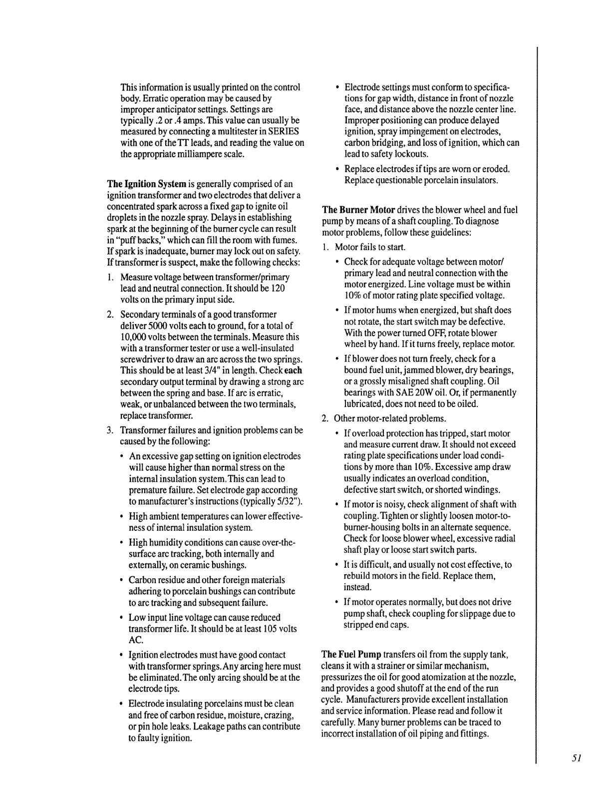
This information is usually printed on the control
body Erratic operation may be caused by
improper anticipator settings. Settings are
typically .2or .4 amps. This value can usually be
measured by connecting amultitester in SERIES
with one of the Tr leads, and reading the value on
the appropriate milliampere scale.
The Ignition System is generally comprised of an
ignition transformer and two electrodes that deliver a
concentrated spark across a fixed gap to ignite oil
droplets in the nozzle spray.Delays in establishing
spark at the beginning of the burner cycle can result
in "puff backs," which can fill the room with fumes.
If spark is inadequate, burner may lock out on safety.
If transformer is suspect, make the following checks:
I. Measure voltage between transformer/primar¢
lead and neutral connection. It should be 120
volts on the primary input side.
2. Second_ terminals of a good transformer
deliver 5000 volts each to ground, for a total of
10,0rX)volts between theterminals. Measure this
with a transformer testeror use a well-insulated
screwdriver to draw an arc across the two springs.
This should be at le_t 3/4" in length, Check each
secondary output terminalby drawing astrong arc
between the spring and base. If arc is erratic,
weak, or unbalanced between the two terminals,
replace transformer.
3. Transformer failures and ignition problems can be
caused by the following:
•An excessive gap setting on ignition electrodes
will cause higher than normal stress on the
internal insulation system.This can lead to
premature failure. Set electrode gap according
to manufacturer's instructions (typically 5/32").
•High ambient temperatures can lower effective-
ness of interna! insulation system.
•High humidity conditions can cause over-the-
surface arc tracking, both internally and
externally, on ceramic bushings.
•Carbon residue and other foreign materials
adhering to porcelain bushings can contribute
to arc trackingand subsequent failure.
,Low input line voltage can cause reduced
transformer life. It should be at least 105 volts
AC.
•Ignition electrodes must have good contact
with transformer springs. Any arcing here must
be eliminated.The only arcing should be at the
electrode tips.
•Electrode insulating porcel_ns must be clean
and free of carbon residue, moisture, crazing,
or pin hole leaks. Leakage paths can contribute
to faulty ignition.
•Electrode settings must conform to specifica-
tions for gap width, distance in front of nozzle
face, and distance above thenozzle center line.
Improper positioning can produce delayed
ignition, spray impingement on electrodes,
carbon bridging, and loss of ignition, which can
lead to safety lockouts.
• Replace electrodes if tips are worn or eroded,
Replace questionable porcelain insulators.
The Burner Motor drives the blower wheel and fuel
pump by means of a shaft coupling.To diagnose
motor problems, follow these guidelines:
1. Motor fails to start.
•Check for adequate voltage between motor/
primary lead and neutral connection with the
motor energized, Line voltage must be within
10% of motor rating plate specified voltage.
•If motor hums when energized, but shaft does
not rotate, the start switch may be defective.
With the power turned OFF, rotate blower
wheel by hand. If it turns freely, replace motor.
•If blower does not turnfreely, check for a
bound fuel unit, jammed blower, dry bearings,
or agrossly misaligned shaft coupling. Oil
bearings with SAE 20W oil. Or, if permanently
lubricated, does not need tobe oiled.
2. Other motor-related problems.
• If overload protection has tripped, start motor
and measure current draw. it should not exceed
rating plate specifications under load condi-
tions by more than 10%.Excessive amp draw
usually indicates an overload condition,
defective start switch, or shorted windings.
• If motor is noisy,check alignment of shaft with
coupling. Tighten or slightly loosen motor-to-
burner-housing bolts in an alternate sequence,
Check for l_se blower wheel, excessive radial
shaft play or loose start switch parts,
• It is difficult, and usually not cost effective, to
rebuild motors in the field. Replace them,
instead.
• If motor operates normally, but does not drive
pump shaft, check coupling for slippage due m
stripped end caps.
The Fuel Pump transfers oil from the supply tank,
cleans it with a strainer or similar mechanism,
pressurizes the oil for good atomization at the nozzle,
and provides a good shutoff at the end of the run
cycle. Manufacturers provide excellent installation
and set€ice information. Please read and follow it
carefully: Many burner problems can be traced to
incorrect installation of oil piping and fittings.
51
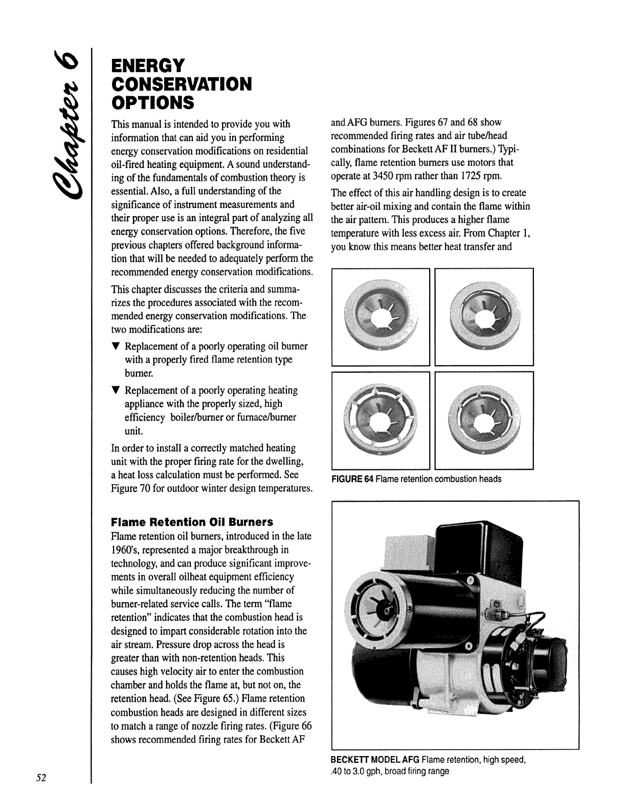
52
OPTIONS
This manual is intended to provide you with
information that can aid you in performing
energy conservation modifications on residential
oil-fired heating equipment. A sound understand-
ing of the fundamentals of combustion theory is
essential. Also, a full understanding of the
significance of instrument measurements and
their proper use is an integral part of analyzing all
energy conservation options. Therefore, the five
previous chapters offered background informa-
tion that will be needed to adequately perform the
recommended energy conservation modifications.
This chapter discusses the criteria and summa-
rizes the procedures associated with the recom-
mended energy conservation modifications. The
two modifications are:
•'Replacement of a poorly operating oil burner
with a properly fired flame retention type
burner.
V Replacement of a poorly operating heating
appliance with the properly sized, high
efficiency boiler/burner or furnace/burner
unit.
In order to install a correctly matched heating
unit with the proper firing rate for the dwelling,
a heat loss calculation must be performed. See
Figure 70 for outdoor winter design temperatures.
Flame Retention 0il Burners
Flame retention oil burners, introduced in the late
1960's, represented a major breakthrough in
technology, and can produce significant improve-
ments in overall oilheat equipment efficiency
while simultaneously reducing the number of
burner-related service calls. The term "flame
retention" indicates that the combustion head is
designed to impart considerable rotation into the
air stream. Pressure drop across the head is
greater than with non-retention heads. This
causes high velocity air to enter the combustion
chamber and holds the flame at, but not on, the
retention head. (See Figure 65.) Flame retention
combustion heads are designed in different sizes
to match a range of nozzle firing rates. (Figure 66
shows recommended firing rates for Beckett AF
and AFG burners. Figures 67 and 68 show
recommended firing rates and air tube!head
combinations for Beckett AF II burners.) Typi-
cally, flame retention burners use motors that
operate at 3450 rpm rather than 1725 rpm.
The effect of this air handling design is to create
better air-oil mixing and contain the flame within
the air pattern. This produces a higher flame
temperature with less excess air. From Chapter 1,
you know this means better heat transfer and
FIGURE64 Flameretentioncombustionheads
BECKETFMODELAFG Flame retention, high speed,
.40to 3.0 gph, broad firing range
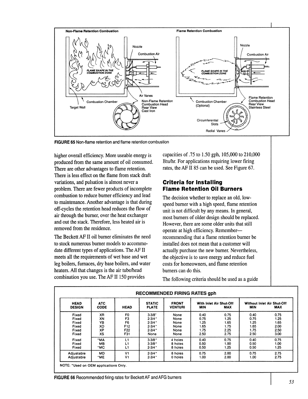
Non-Flame Retention Combustion Flame Retention Combustion
Nozzle
Combustion Air
Target Wall
r Vanes
CombustionChamber Non-Flame Retention
Combustion Head
Rear V_ew
Cast Iron
Nozzle
Rame Retention
_\ Combustion Chamber Combustion Head
(Optional) Rear View
Stainless Steel
Circumferential
Slots
Radial Vanes
FIGURE 65 Non-flame retentionand flame retention combustion
higher overall efficiency. More useable energy is
produced from the same amount of oil consumed.
There are other advantages to flame retention.
There is less effect on the flame from stack draft
v_ations, and pulsation is almost never a
problem. There are fewer products of incomplete
combustion to reduce burner efficiency and lead
to maintenance. Another advantage is that during
off-cycles the retention head reduces the flow of
air through the burner, over the heat exchanger
and out the stack. Therefore, less heated air is
removed from the residence.
The Beckett AF II oil burner eliminates the need
to stock numerous burner models to accommo-
date different types of applications. The AF II
meets all the requirements of wet base and wet
leg boilers, furnaces, dry base boilers, and water
heaters. All that changes is the air tube/head
combination you use. The AF II 150 provides
capacities of .75 to 1,50 gph, 105,000 to 210,000
Btu,qar.For applications requiring lower firing
rates, the AF II 85 can be used. See Figure 67.
Criteria for Installing
Flame Retention Oil Burners
The decision whether to replace an old, low-
speed burner with a high speed, flame retention
unit is not difficult by any means. In general,
most burners of older design should be replaced.
However, there are some older units that still
operate at high efficiency. Remember--
recommending that a flame retention burner be
installed does not mean that a customer will
actually purchase the new burner. Nevertheless,
the objective is to save energy and reduce fuel
costs for homeowners, and flame retention
burners can do this.
The following criteria should be used as a guide
RECOMMENDED FIRING RATES gph
H_D ATC STATIC FRONT With Inlet Air Shut.Off Without inlet A|r Shut.Off
DESIGN CODE HEAD PLATE VENTURI MIN MAX MIN MAX
Fixed XR F0 3-3/8" None 0,40 0.75 0A0 0.75
Fixed XN F3 2-3/4" None 0.75 1,25 0,75 1.25
Fixed YB F6 2-314" None 1.25 1,65 t,25 1.65
Fixed XO F12 2-3/4" None 1.65 175 !,65 2,00
Fixed XP F22 2-3/4" None 1.75 2.25 1_75 2.50
Fixed XS F31 None None 2.50 2,75 2.50 3.00
Fixed "MA L1 3-3/8" 4 holes 0,40 0.75 0A0 0,75
Fixed MB L1 3-3/8" 8 holes 0,50 1,00 0.50 1.00
Fixed * MC L1 2.3/4" 8holes 0_50 1.25 0.50 1,25
Adjustable MD Vl 2-3/4" 8holes 0,75 2,00 0.75 2,75
Adjustable *ME Vl 2-3t4 _ 0 holes 1.00 2.00 1.00 2.75
NOTE: *Used on OEM applications Only.
FIGURE 66 Recommended firing rates for BeckettAF andAFG burners [
I53
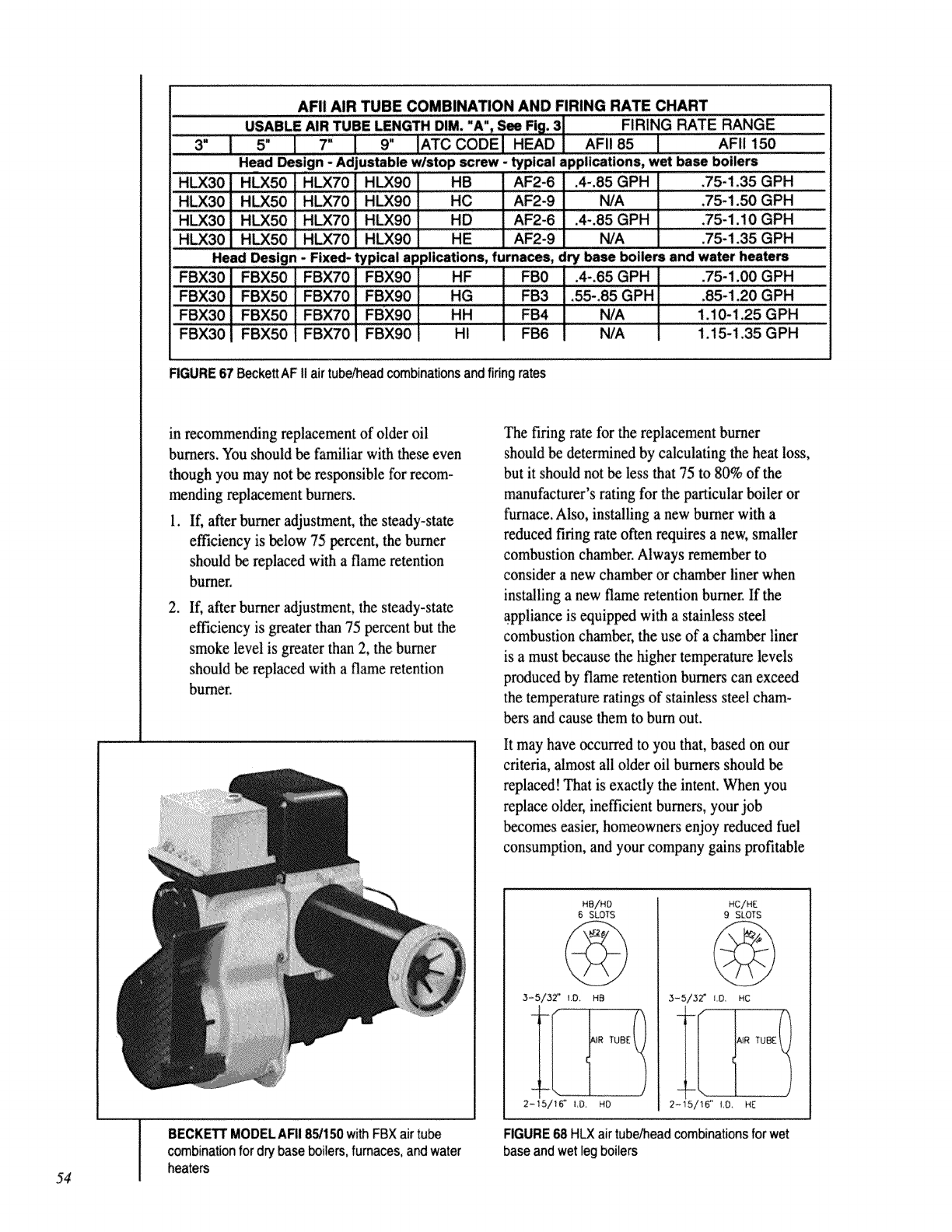
54 i
AFII AIR TUBE COMBINATION AND FIRING RATE CHART
FIRING RATE RANGE
AFII 85 I AFII 150
Head Design -Adjustable w/stop screw -typical applications, wet base boilers
H_50 HUX70 HLX90 HB AF2-6 .4-.85 GPH ,75-1.35 GPH
HLX30" H_50 ' HLx70" Hffxg0 _HC AF2-9 N/A ,75-1.50 GPH
HLX30 L HLX50 HLX70 H_90 ......HD AF2-6 .4-,85 GPH .75-1.10 GPH
HLX30 HLX50 H_70 HLX90 HE AF2-9 t_A .75-1.35 GPH
Head Desl n - Fixed- typical applications, furnaces, dry base boilers and water heaters
FBX50 FBX70 FBX90 HF FB0 .4-,65 GPH .75-1.00 GPH
FBX30 FBX70 FBX90 HG FB3 .55-.85 GPH .85-1.20 GPH
' FBX30 i FBX50 ' FBX70 ' FBX90 RH N/A 1.10"1,25 GPH
HI N/A 1.15-1.35 GPH
RGURE 67 Beckett AF II air tub_ead combinationsand firing rates
in recommending replacement of older oil
burners. You should be familiar with these even
though you may not be responsible for recom-
mending replacement burners.
1. If, after burner adjustment, the steady-state
efficiency is below 75 percent, the burner
should be replaced with a flame retention
burner.
,If, after burner adjustment, the steady-state
efficiency is greater than 75 percent but the
smoke level is greater than 2, the burner
should be replaced with a flame retention
burner.
The firing rate for the replacement burner
should be determined by calculating the heat loss,
but it should not be less that 75 to 80% of the
manufacturer's rating for the particular boiler or
furnace. Also, installing a new burner with a
reduced firing rate often requires a new, smaller
combustion chamber. Always remember to
consider a new chamber or chamber liner when
installing a new flame retention burner. If the
appliance is equipped with a stainless steel
combustion chamber, the use of a chamber liner
is a must because the higher temperature levels
produced by flame retention burne_ can exceed
the temperature ratings of stainless steel cham-
bers and cause them to burn out.
It may have occurred to you that, based on our
criteria, almost all older oil burners should be
replaced! That is exactly the intent. When you
replace older, inefficient burners, your job
becomes easier, homeowners enjoy reduced fuel
consumption, and your company gains profitable
BECK_ MODELAFI185/150withFBXairtube
combinationfor drybaseboilers,fumaces,andwater
heaters
HS/HO
6 SLOTS
3=5/32" !,0 HB
2-15/16" _0 HO
HC/HE
9 SLOTS
3-5/32 _ I.o, HC
2/HE
RGURE 68 HLX air tube/head combinations for wet
base and wet leg boilers
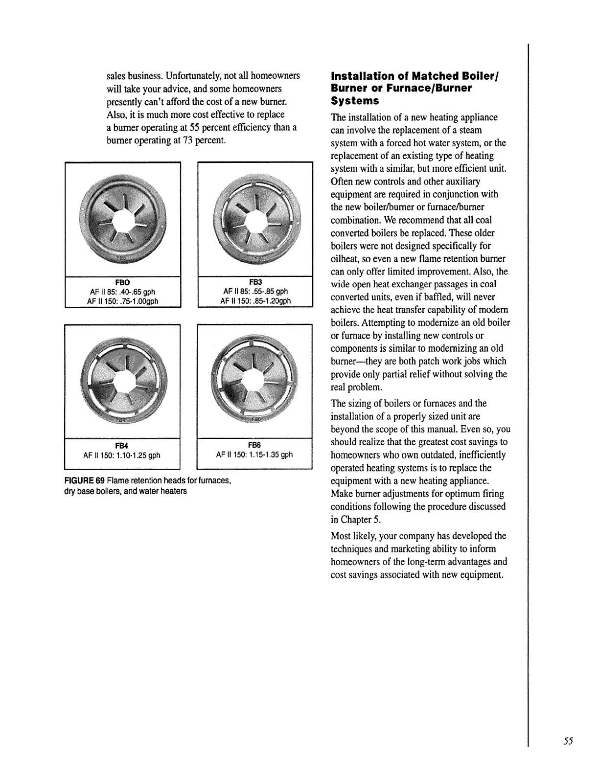
sales business. Unforpanately, not all homeowners
will take your advice, and some homeowners
presently can't afford the cost of a new burner,
Also, it is much more cost effective to replace
a burner operating at 55 percent efficiency than a
burner operating at 73 percent.
FBO
AF II 85:.40_.65 gph
AF 11150:,75-1,00gph
FB3
AF II 85:,55-.85 gph
AF II 150: ,85-1,20gph
FB4
AF ii 150:1A0-1.25gph
FB6
AF II 150:1A5-1,35 gph
FIGURE69 Flameretentionheadsforfurnaces,
drybaseboilers,andwaterheaters
Installation of Matched Boiler/
Burner or Furnace/Burner
The installation of a new heating appliance
can involve the replacement of a steam
system with a forced hot water system, or the
replacement of an existing type of heating
system with a similar, but more efficient unit.
Often new controls and other auxiliary
equipment are required in conjunction with
the new boiler/burner or furnace/burner
combination. We recommend that all coal
converted boilers be replaced. These older
boilers were not designed specifically for
oilheat, so even a new flame retention burner
can only offer limited improvement. Also, the
wide open heat exchanger passages in coal
converted units, even if baffled, will never
achieve the heat transfer capability of modern
boilers. Attempting to modernize an old boiler
or furnace by installing new controls or
components is similar to modernizing an old
burner--they are both patch work jobs which
provide only partial relief without solving the
real problem.
The sizing of boilers or furnaces and the
installation of a properly sized unit are
beyond the scope of this manual. Even so, you
should realize that the greatest cost savings to
homeowners who own outdated, inefficiently
operated heating systems is to replace the
equipment with a new heating appliance.
Make burner adjustments for optimum firing
conditions following the procedure discussed
in Chapter 5.
Most likeb; your company has developed the
techniques and marketing ability to inform
homeowners of the long-term advantages and
cost savings associated with new equipment.
55
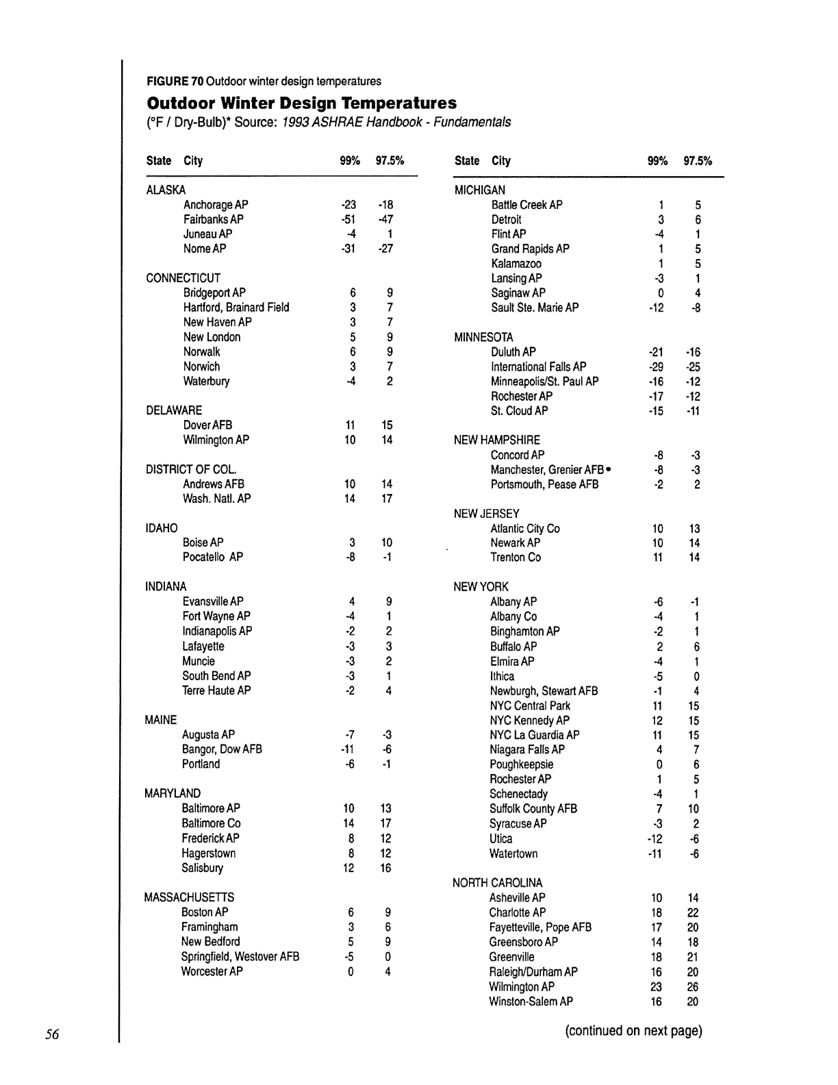
RGURE 70 Outdoor winterdesign temperatures
Outdoor Winter Design Temperatures
(°F /Dry-Bulb)* Source: 1993 ASHRAE Handbook -Fundamentals
State City 99% 97.5% State City
ALASKA
AnchorageAP -23 -18
FairbanksAP -51 -47
JuneauAP -4 1
NomeAP -31 -27
CONNECTICUT
BridgeportAP 6
Hartford,BrainardField 3
NewHavenAP 3
NewLondon 5
Norwalk 6
Norwich 3
Waterbury -4
g
7
7
9
9
7
2
DELAWARE
DoverAFB 11 15
WilmingtonAP 10 14
DISTRICTOF COL.
AndrewsAFB 10
Wash.NatLAP 14
14
17
IDAHO
BoiseAP 3 10
PocatelloAP -8 -1
INDIANA
Evansvi!leAP 4
FortWayneAP -4
IndianapolisAP -2
Lafayette -3
Muncie -3
SouthBendAP -3
TerreHauteAP -2
9
1
2
3
2
1
4
MAINE
AugustaAP -7 -3
Bangor,DowAFB -11 -6
Portland -6 -1
MARYLAND
BaltimoreAP 10 13
BaltimoreCo 14 17
FrederickAP 8 12
Hagerstown 8 12
Salisbury 12 16
MASSACHUSETTS
BostonAP 6
Framingham 3
NewBedford 5
Springfield,WestoverAFB -5
WorcesterAP 0
9
6
9
0
4
MICHIGAN
BattleCreekAP
Detroit
RintAP
GrandRapidsAP
Kalamazoo
LansingAP
SaginawAP
SaultSte.MarieAP
MINNESOTA
DuluthAP
InternationalFallsAP
Minneapolis/St.PaulAP
RochesterAP
St.CloudAP
NEWHAMPSHIRE
ConcordAP
Manchester,GrenierAFB•
Portsmouth,PeaseAFB
NEWJERSEY
AtlanticCity Co
NewarkAP
TrentonCo
NEWYORK
AlbanyAP
AlbanyCo
BinghamtonAP
BuffaloAP
ElmiraAP
Ithica
Newburgh,StewartAFB
NYCCentralPark
NYCKennedyAP
NYCLaGuardiaAP
NiagaraFallsAP
Poughkeepsie
RochesterAP
Schenectady
SuffolkCountyAFB
SyracuseAP
Utica
Watertown
NORTHCAROLINA
AshevilleAP
CharlotteAP
Fayetteville,PopeAFB
GreensboroAP
Greenville
Raleigh/DurhamAP
WilmingtonAP
Winston-SalemAP
1
3
-4
1
1
-3
0
-12
-21
-29
-16
-17
-15
-8
-8
.2
10
10
11
-6
-4
-2
2
-4
-5
-1
11
12
11
4
0
1
-4
7
-3
-12
-11
97.5%
5
6
1
5
5
1
4
-8
-16
-25
-12
-12
-11
-3
-3
2
13
14
14
-1
1
1
6
1
0
4
15
15
15
7
6
5
1
10
2
-6
-6
10 14
18 22
17 20
14 18
18 21
16 20
23 26
16 20
56 (continued on next page)
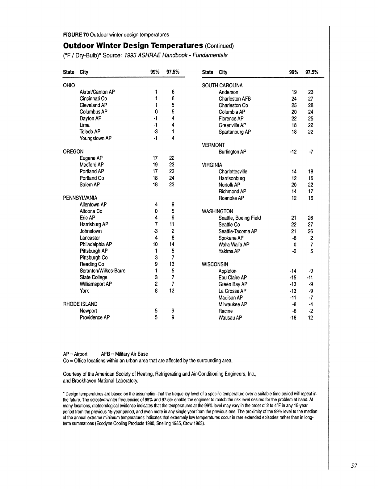
FIGURE 70 Outdoor winterdesign temperatures
Outdoor Winter Design Temperatures (Continued)
(°F /Dry-Bulb)* Source: 1993 ASHRAE Handbook -Fundamentals
State City 99°/o 97.5% State City
OHIO SOUTHCAROLINA
AkrordCantonAP 1 6 Anderson
CincinnatiCo 1 6 CharlestonAFB
ClevelandAP 15CharlestonCo
ColumbusAP 0 5 ColumbiaAP
DaytonAP -1 4 FlorenceAP
Uma -1 4 GreenvilleAP
ToledoAP -3 I SpartanburgAP
YoungstownAP -I 4
VERMONT
OREGON BurlingtonAP
EugeneAP 17 22
MedfordAP 19 23 VIRGINIA
PortlandAP 17 23 Charlottesville
PortlandCo 18 24 Harrisonburg
SalemAP 18 23 NorfolkAP
RichmondAP
PENNSYLVANIA RoanokeAP
AllentownAP 4 9
AltoonaCo 0 5
ErieAP 4 9
HarrisburgAP 7 11
Johnstown -3 2
Lancaster 4 8
PhiladelphiaAP 10 14
PittsburghAP 1 5
PittsburghCo 3 7
ReadingCo 9 13
Scrantor,JWilkes-Barre 1 5
StateCollege 3 7
WiliiamsportAP 2 7
York 8 12
RHODEISLAND
Newport
ProvidenceAP
5
59
g
99%
19
24
25
2O
22
18
18
-12
97.5%
23
27
28
24
25
22
22
-7
14 18
12 16
2O 22
14 17
12 16
WASHINGTON
Seattle,BoeingField 21 26
SeattleCo 22 27
Seattle-TacomaAP 21 26
SpokaneAP -6 2
WallaWallaAP 0 7
YakimaAP -2 5
WISCONSIN
Appleton -14 -9
EauClaireAP -15 -11
GreenBayAP -13 -9
LaCrosseAP -13 -9
MadisonAP -11 .7
MilwaukeeAP -8 -4
Racine -6 -2
WausauAP -16 -t2
AP= Airport AFB= MilitaryAirBase
Co= Office locationswithinan urbanareathatare affectedby thesurroundingarea.
Courtesyof theAmericanSocietyof Heating,RefrigeratingandAir-ConditioningEngineers,Inc.,
andBrookhavenNationalLaboratory.
* Designtemperaturesare basedon theassumptionthat the frequencylevelof a specifictemperatureover asuitabletimeperiodwill repeatin
the future.The selectedwinterfrequenciesof 99%and 97.5% enablethe engineertomatch therisklevel desiredfor the problemat hand.At
manylocations,meteorologicalevidenceindicatesthat thetemperaturesat the 99% levelmayvary in theorderof 2 to 4°F inany 15-year
periodfrom the previous15-yearperiod,andeven moreinany singleyearfrom the previousone. The proximityof the 99% levelto the median
of the annual extrememinimumtemperaturesindicatesthatextremelylow temperaturesoccurin rareextendedepisedesratherthanin long-
term summations(EcedyneCoolingProducts1980,Snelling 1985,Crow 1963).
5?
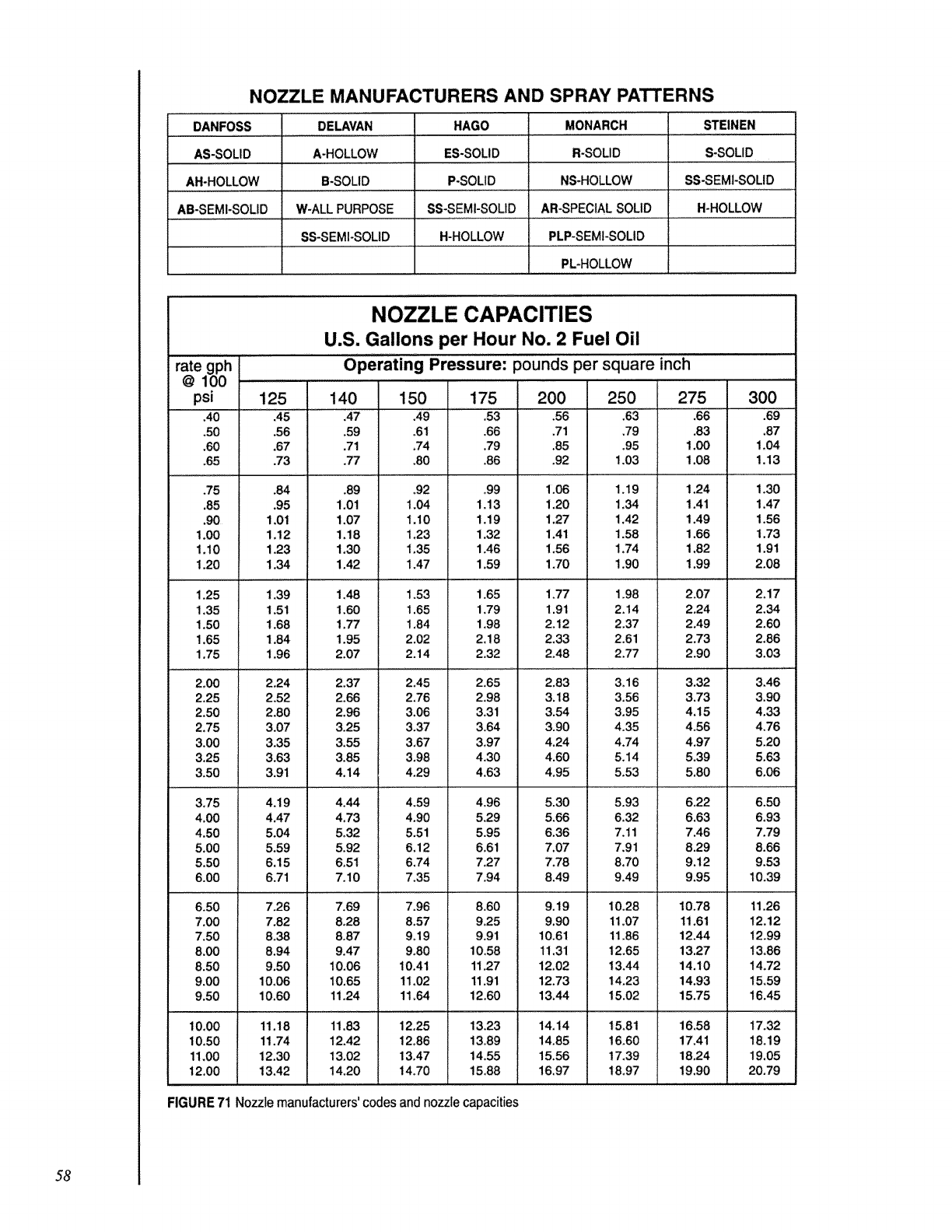
NOZZLE MANUFACTURERS AND SPRAY PATTERNS
DANFOSS
AS-SOLID
AH-HOLLOW
AB-SEMI-SOLID
STEINEN
S-SOLID
DELAVAN
A-HOLLOW
B-SOLID
W-ALL PURPOSE
SS-SEMI-SOUD
HAGO
ES-SOLID
P-SOLID
SS-SEMI-SOLID
H-HOLLOW
MONARCH
R-SOLID
NS-HOLLOW
AR-SPECIALSOLID
PLP-SEMI-SOLID
PL-HOLLOW
SS-SEMI-SOLID
H-HOLLOW
NOZZLE CAPACITIES
U.S. Gallons per Hour No. 2 Fuel Oil
Operating Pressure: pounds per square inch
rate gph
@100 ................
psi 140 150 175
.40 .45 A7 ,49 .53
.50 .56 .59 .61 .66
.60 .67 ,71 ,74 .79
.65 .73 .77 .80 .86
.75
,85
,90
1_00
1.10
1°20
1,25
1,35
1.50
1.65
1,75
2,00
2.25
2.50
2.75
3.00
3.25
3.50
3,75
4.00
4.50
5.00
5.50
6.00
6.50
7.00
7.50
8.00
8.50
9.00
9.50
10.00
10,50
11.00
12.00
.84
.95
1,01
1,12
1.23
1.34
1.39
1,51
1.68
1.84
1.96
2,24
2.52
2.80
3.07
3.35
3.63
3.91
4.19
4.47
5.04
5,59
6,15
6,71
7.26
7.82
8.38
8.94
9.50
10.06
10,60
11.18
11.74
12,30
13.42
.89
1.01
1.07
1.18
1,30
1,42
1.48
1.60
1,77
1,95
2.07
2.37
2,66
2.96
3.25
3.55
3.85
4,14
,92
1.04
1,10
t,23
1.35
1.47
1,53
1.65
1.84
2.02
2.14
2,45
2,76
3.06
3.37
3,67
3.98
4.29
,99
1.13
1.19
1,32
1.46
1.59
1,65
1.79
1,98
2,18
2.32
2.65
2.98
3,31
3.64
3,97
4.30
4.63
4.44
4,73
5,32
5.92
6,51
7.10
7.69
8,28
8.87
9.47
10,06
10.65
11.24
11.83
12.42
13.02
14.20
4.59
4.90
5.51
6.12
6.74
7.35
275 300
.66 169
.83 ,87
1,00 1,04
1.08 1.13
1.24 1.30
1,41 1,47
1,49 1.56
1.66 1.73
1,82 1,91
1.99 2.08
2.17
2,34
2.60
2,66
3.03
3.46
3,90
4.33
4,76
5.20
5.63
6,06
6,50
6,93
7.79
8.66
9.53
10.39
11.26
12.12
12.99
13,86
14.72
15,59
16.45
17.32
18,19
19.05
20.79
7.96
8.57
9.19
9.80
10.41
11,02
11,64
12,25
12_86
13.47
14.70
4.96
5.29
5.95
6,61
7.27
7.94
8,60
9,25
9.91
10.58
11,27
11.91
12.60
13.23
13.89
14.55
15,88
FIGURE 71 Nozzle manufacturers' codesand nozzlecapacities
200
.56
,71
.85
.92
1.06
1.20
1.27
1,41
1,56
1.70
1.77
1.91
2,12
2.33
2.48
2.83
3.18
3.54
3.90
4,24
4,60
4.95
5.30
5,66
6.36
7.07
7.78
8,49
9.19
9,90
10,61
11,31
12.02
12,73
13,44
14.14
14.85
15.56
16,97
250
.63
.79
.95
t .03
1.19
1.34
1.42
1,58
1,74
1.90
1.98 2.07
2.14 2.24
2.37 2,49
2.61 2.73
2.77 2,90
3_16 3.32
3.56 3.73
3.95 4,15
4.35 4.56
4.74 4.97
5.14 5.39
5.53 5.80
5.93 6.22
6.32 6,63
7.11 7.46
7.91 8.29
8,70 9.12
9.49 9,95
10.28 10.78
11,07 11.61
11.86 12,44
t2.65 13.27
13A4 14.10
14.23 14.93
15.02 15,75
15.81 16.58
16.60 17.41
17.39 18,24
18.97 19.90
58
Call the Beckett Service Hotline
Youcan really expect more from Beckett.
0 5
FormNo. 6380R97
© 1997R.W.Beckett Corporation
Printed in U.S.A.
