Beckwith Electric M2913 Universal Data Transceiver User Manual M 2911 SP 00MC1 11 02
Beckwith Electric Co., Inc. Universal Data Transceiver M 2911 SP 00MC1 11 02
Exhibit D Users Manual per 2 1033 b3
BlueJay™ Wireless
Data Transceiver
M-2913
CONTROLS
• Provides direct sequence spread spectrum peer-to-peer, point-to-
point, point-to-multipoint and master/slave high speed (1 Mbps) data
transmission rates at ranges up to 1500 feet
• Interfaces with host computer running Windows 98–SE or later
• Substation hardened to withstand temperatures from -40 to +80
degrees C and humidity up to 95%
M-2913 BlueJay Wireless Data Transceiver
–2–
WARNING
This equipment has been tested and found to comply with the limit requirements, pursuant to Part 15.247 of
the FCC Rules. These limits are designed to provide reasonable protection against harmful interference when
the equipment is operated in a commercial environment. This equipment generates, uses, and can radiate
radio frequency energy, and, if not installed and used in accordance with the instruction manual, may cause
harmful interference to radio communications. Operation of this equipment in a residential area is likely to
cause harmful interference in which case the user will be required to correct the interference at his own
expense.
Only the antenna provided is authorized for use with the M-2913. If the antenna is lost or damaged, please
contact Beckwith Electric Co., Inc. to secure a replacement antenna.
This product generates, uses, and can radiate radio frequency (RF). If it is not installed and used in
accordance with the operating instructions, it can cause harmful interference to communications. If this
equipment causes harmful interference to radio or television reception, the user should try and correct the
interference by:
• Reorienting or relocating the receiving/transmitting antenna
• Increasing the separation between the equipment and the M-2913
• Connecting the equipment into an outlet on a different circuit from the M-2913.
If these do not correct the interference, consult an experienced radio/television technician for assistance.
Correcting such interference is the responsibility of the user, not the manufacturer.
Changes or modifications not expressly approved by Beckwith Electric Co., Inc. may void the user's
authority to operate the equipment.
FCC Radiation Exposure Statement
This equipment complies with FCC radiation exposure limits set forth for uncontrolled equipment. This
equipment should be installed and operated with a minimum distance of at least 20 cm between the radiator
and person's body (excluding extremities) and must not be located or operated with any other antenna or
transmitter.
–3–
M-2913 BlueJay Wireless Data Transceiver
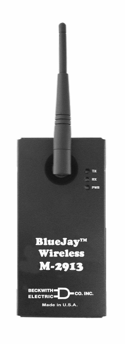
The M-2913 BlueJay™ Wireless Data Transceiver is a self-contained short-range wireless communication
device (SRD) that is used for transferring data between a host computer and Intelligent Electrical Device
using the Universal Serial Bus (USB). The M-2913 is based on an Intersil direct sequence spread spectrum
chip set that operates in the 2.4 GHz ISM band. The M-2913 design meets the category for low power
devices (LPDs) standard requirement for license-free operation.
Interface
The M-2913 uses the standard USB B-connector to connect to the host computer. The transmission rate of
the USB using the interrupt endpoint is TBD Mbps.
Data Transmission:
• Error Detection – 16 bit CRC
• Maximum throughput – 500 Kbps
Communication
The M-2913 conditions the data and transmits it over a half-duplex direct sequence spread spectrum radio
operating in the 2.4 GHz ISM band. The over-the-air data rate is TBD Mbps.
Transmit:
• 1 Mbps
Receive:
• 1 Mbps
The M-2913 BlueJay Wireless Data Transceiver is used with a laptop or desktop computer, and if it is to be
used within a metal-enclosed structure, a cable extension must be used and the antenna mounted externally.
Antennas must be oriented in the same plane and located in view of the corresponding transceiver. Beckwith
Electric cable extensions are available in 18", 6' and 13' lengths (See Accessories).
■NOTE: For maximum range, all antennas must be oriented in the same plane.
Accessories
18" Cable Extension – Beckwith Electric Part No. 420-00395
6' Cable Extension – Beckwith Electric Part No. 420-00391
13' Cable Extension – Beckwith Electric Part No. 420-00392
M-TBD – TBD' USB Extension Cable
Power
The M-2913 gets its power from the host computer. When the M-2913 is plugged into the USB A-type
connector resident on the host, power is provided. The maximum current used by the M-2913 is 500 mA.
Configuration
The address will be set by the user application. The M-2913 must be run under Windows™ 98-SE version, or
later.
M-2913 BlueJay Wireless Data Transceiver
–4–
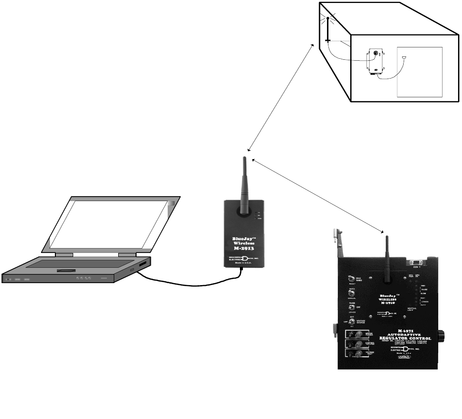
Typical Connections Guide
The M-2913 can be applied in one of two methods.
1. Point-to-Point Configuration: Between an M-2913 and an M-2911, with the M-2913 connected
to a host computer running Windows™ 98-SE or later, and the M-2911 connected to a PC,
modem, or another IED.
Detailed elements of a typical Point-to-Point configuration are as follows:
a. One M-2913 is connected to a PC USB port using a typical USB cable.
b. The second M-2913 is connected to the RS-232 port of a M-2667 Autodaptive® Tapchanger
Control using an RS-232 straight through cable and gender changer.
Communications can now be established between the PC and M-2667 as if they were directly
connected. In this example, if the SLIMcom Communications Software were to be used, the
software should detect that the M-2913 is connected to the PC, and then prompt the user for an
address.
2. Point-to-Multipoint Configuration (also known as Master/Slave): In the Point-to-Multipoint
configuration, one M-2913 is configured as the Master unit with multiple-connected IED units
configured as Slaves (see AT Commands in the M-2911 Specifications for Master/Slave setup).
This configuration may be used where, for example, the Master unit is located in a control house
and the slaves are spread out throughout a substation yard.
Detailed elements of a typical Point to Multipoint configuration are as follows:
a. One M-2913 (Master) is connected to the USB port of the host computer. It is configured as
a master unit.
b. Nine IEDs are located throughout a substation yard, each with an M-2911 connected to it
using a straight through RS-232 cable connected to the IED COM Port.
Each M-2911 is configured as a Slave unit. (See the Addressing section under AT
commands in the M-2911 Specification Guide for details.)
c. At a remote location, an RTU has been configured to dial the modem located at the control
house and poll each unit at the substation at 5 minute intervals. For this application to
operate successfully, the RTU cannot poll all units simultaneously.
Optimal Antenna Configuration
A variety of antenna types can be used with the M-2913. The antennas available from Beckwith Electric are
FCC qualified for use with our product. Use of an antenna not supplied by Beckwith Electric could violate
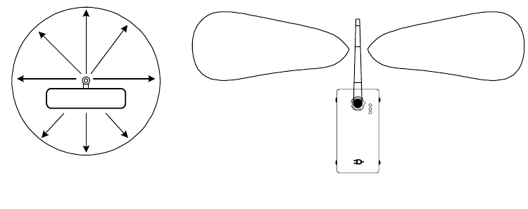
FCC licensing and result in fines to the user. All antenna types currently offered are considered omnidirec-
tional antennas. An omnidirectional antenna is so named because it is designed to radiate equally in all
directions horizontal to the antenna. These antennas have been designed to radiate in a horizontal pattern,
which is best approximated by a toroid, or “doughnut” illustrated in Figure 7. This is also why most
omnidirectional antennas are rated to have a three dB gain over a true spherical radiator. The antenna
appears to have a power gain of two times (3 dB), compared to a true spherical radiator.
Optimum performance of Beckwith Electric-supplied antennas is obtained when the main axis of the antenna
is located perpendicular to the Earth’s surface. This allows the toroidal pattern to radiate the maximum range
in each dimension. When the RF energy of the radiation pattern contacts ground, or a grounded surface, it is
absorbed in varying degrees depending on the conductivity of the surface. It is important to have a clear
view, or “line-of-sight” between antennas as illustrated in Figure 8. Any obstructions between the antennas
can absorb some energy, and can reduce the range of operation. Also, if a grounded plane is located parallel
to and close to the antenna, such as a wall located next to the antenna, it can change the impedance match
between the antenna and free-space. This condition can severely reduce the range that can be normally
obtained in unblocked directions. A rule of thumb is to ensure that any grounded objects are kept at least 10
wavelengths (50 inches for 2.4 GHz) away from the antenna in the plane of radiation (Figure 8). 50 inches is
only a guideline, and may be shortened if extreme range is not required. Some experimentation with antenna
location will be needed to optimally set up wireless in a substation environment.
–5–
M-2913 BlueJay Wireless Data Transceiver
The following should be considered when planning a wireless project:
1. The resonant frequency of the water molecule is within the 2.4 GHz band, which can cause a
reduction in range during rainy weather.
2. Trees (especially pine trees) can have >80% water content, and as such can be a barrier to
wireless signals. As long as antennas have a direct line of sight, trees should not cause a
problem.
3. Proximity of the wireless project to cell towers, 2.4 GHz telephones, WiFi access points, or
Bluetooth wireless devices.
If you are experiencing difficulty communicating through the M-2913's, ensure that the antennas are:
• In direct line of sight with each other.
• Oriented vertically with respect to earth.
• Within 1500 Ft.
You may be encountering interference from another source. Some examples of interference are
cell towers, 2.4 GHz telephones, WiFi access points, or Bluetooth wireless devices. If the
interference cannot be compensated for by relocating the antennas or reducing the distance
between them, then other antenna types may be necessary. Please contact Beckwith Electric if
you would like to discuss other antenna options.
BlueJayTM
Wireless
M-2913
M a de in U.S .A.
PWR
RX
TX
CO. IN C.
ELECTRIC
BECKWITH
M-2913
Top View
Side View
Figure 8 Top and Side View
M-2913 BlueJay Wireless Data Transceiver
–6–
BlueJayTM
Wireless
M-2911
Made in U.S.A.
PWR
RX
TX
CO.INC.
EL ECT R I C
BE C KW ITH IED
M-2911
No Obstructions
Between Antennas
Beckwith Electric M-6200
Series Autodaptive Control
equipped with an M-2910
BlueJay Wireless Data
Transceiver
IED equipped with an
M-2911 BlueJay Wireless
Data Transceiver
USB Cable
Laptop
Figure 9 Line of Site Orientation of Antennas
Environmental
Temperature: Proper operation maintained from –40°C to +80°C.
Humidity: Proper operation is maintained up to 95% relative humidity (non-condensing).
Environmental Protection: The power supply printed circuit board is conformally coated to inhibit fungus
growth.
Enclosure: 1/16" Aluminum.
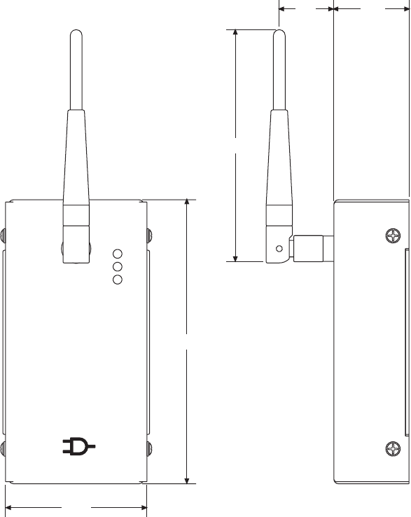
Physical
Size: 5.88" high (with antenna 9.43") x 3.88" wide x 2.5" deep (14.58 cm (23.1) x 9.9 cm x 6.13 cm). See
Figure 10 for dimensional drawing.
Weight: 2.13 oz (60 grams)
Enclosure meets requirements of IP30.
–7–
M-2913 BlueJay Wireless Data Transceiver
Made in U.S.A.
WIRELESS
M-2913
PWR
TX
RX
BlueJay
TM
CO. INC.
ELECTRIC
BECKWITH
5.52
4.51
2.75
1.461.06
Figure 10 Outline Dimensions

M-2913 BlueJay Wireless Data Transceiver
–8–
Safety and Cautions
8WARNING: The installation, maintenance, and/or operation of this equipment could present
potentially unsafe conditions, including, but not limited to, electrical shock or improper voltage to
components. Improper operation could cause personal injury, death, or damage to property.
Read all safety instructions before operating the M-2913, and retain them for further reference. Follow all
operating and usage instructions, and make special note of the following safety symbols:
– This sign warns that the area is connected to a dangerous high voltage, and you must
never touch it.
– This sign means that you should refer to the corresponding section of the operation
manual for important information before proceeding.
Do not attempt to perform maintenance or service functions that are not described in the operating
instructions. Instead, refer all such service requirements to Beckwith Electric Co., Inc. Unit must be returned
for service in secure (preferably original) packaging. Shipping cost must be paid by user.
Only the antenna provided is authorized for use with the M-2913. If the antenna is lost or damaged, please
contact Beckwith Electric Co., Inc. to secure a replacement antenna.
This product generates, uses, and can radiate radio frequency (RF). If it is not installed and used in
accordance with the operating instructions, it can cause harmful interference to communications. If this
equipment causes harmful interference to radio or television reception, the user should try and correct the
interference by:
• Reorienting or relocating the receiving/transmitting antenna
• Increasing the separation between the equipment and the M-2913
• Connecting the equipment into an outlet on a different circuit from the M-2913.
If these do not correct the interference, consult an experienced radio/television technician for assistance.
Correcting such interference is the responsibility of the user, not the manufacturer.
Compliance
This device has been designed to operate with an antenna having a maximum gain of 2 dB. Antenna having
a higher gain are strictly prohibited per regulations of Industry Canada. The required antenna impedance is 50
ohms.
This equipment has been tested and found to comply with the limit requirements, pursuant to Part 15.247 of
the FCC Rules and Industry Canada RSS-210 and ICES-003. These limits are designed to provide
reasonable protection against harmful interference when the equipment is operated in a commercial
environment. This equipment generates, uses, and can radiate radio frequency energy, and, if not installed
and used in accordance with the instruction manual, may cause harmful interference to radio communica-
tions. Operation of this equipment in a residential area is likely to cause harmful interference in which case
the user will be required to correct the interference at his own expense.
This device complies with Part 15 of the FCC Rules. Operation is subject to the following two conditions:
1. this device may not cause harmful interference, and
2. this device must accept any interference received, including interference that may cause
undesired operation.
–9–
M-2913 BlueJay Wireless Data Transceiver
Patent & Warranty
■NOTE: Changes or modifications to the unit not expressly approved by Beckwith Electric Co. may void
the user's authority to operate the equipment.
U.S. Patent for the M-2913 BlueJay™ Wireless Data Transceiver is pending.
The M-2913 BlueJay Wireless Data Transceiver is covered by a five year warranty from the date of shipment.
Specification is subject to change without notice.

I
S
O
9
0
0
1
:
2
0
0
0
R
e
g
i
s
t
e
r
e
d
BECKWITH ELECTRIC CO., INC.
6190 - 118th Avenue North • Largo, Florida 33773-3724 U.S.A.
PHONE (727) 544-2326 • FAX (727) 546-0121
E-MAIL marketing@beckwithelectric.com
WEB PAGE www.beckwithelectric.com
800-2913-SP-00(C) 07/04
© 2003 Beckwith Electric
Printed in U.S.A. (8.26.03)