Behavior Tech Computer KB5109AC Model 5109 Keyboard User Manual 5109AC USB english
Behavior Tech Computer Corporation Model 5109 Keyboard 5109AC USB english
Manual

5109AC KEYBOARD USER'S GUIDE
Product Overview
This document describes the functional specification of standard USB keyboard and standard USB
Hub keyboard. Its function is fully compatible with the Universal Serial Bus Specification
Revision 1.1 as well as the Human Interface Devices (HID) class specification 1.1.
USB Interface Features:
Ø USB is a "must-have" feature in the current market.
Ø The instant way to expand your PC. You never to open your PC and you don't need to worry
about add-in cards, DIP switch setting or IRQs.
Ø "Hot-swapping" feature: You don't even need to shut down and restart your PC to attach or
remove a peripheral. Just plug it in and go!
The ACPI Power Management Keys and Their Functions
System requirement:
Ø Microsoft Windows 98 operating system.
Ø The system supporting ACPI or APMII.
Ø ATX motherboard and ATX power supply.
The functions of the power management are specified and performed by Windows 98 operating
system, no vendor-specified driver is needed to use them, but the Windows 98 operating system
is necessary. There could be one or two or three ACPI power management keys on the keyboard,
those functions are as follows.
Power off key: Power down the system.
Sleep key: Put the system to sleep.
Wake up key: Wake up or powers up the system.
Power key: (Single key with three functions above)
Ø Press this key and hold over four seconds to power down the system.
Ø Press this key and release it within four seconds to put the system to sleep.
Ø When the system is asleep or powered down, press this key and release it within four
seconds to wake up or power up the system.
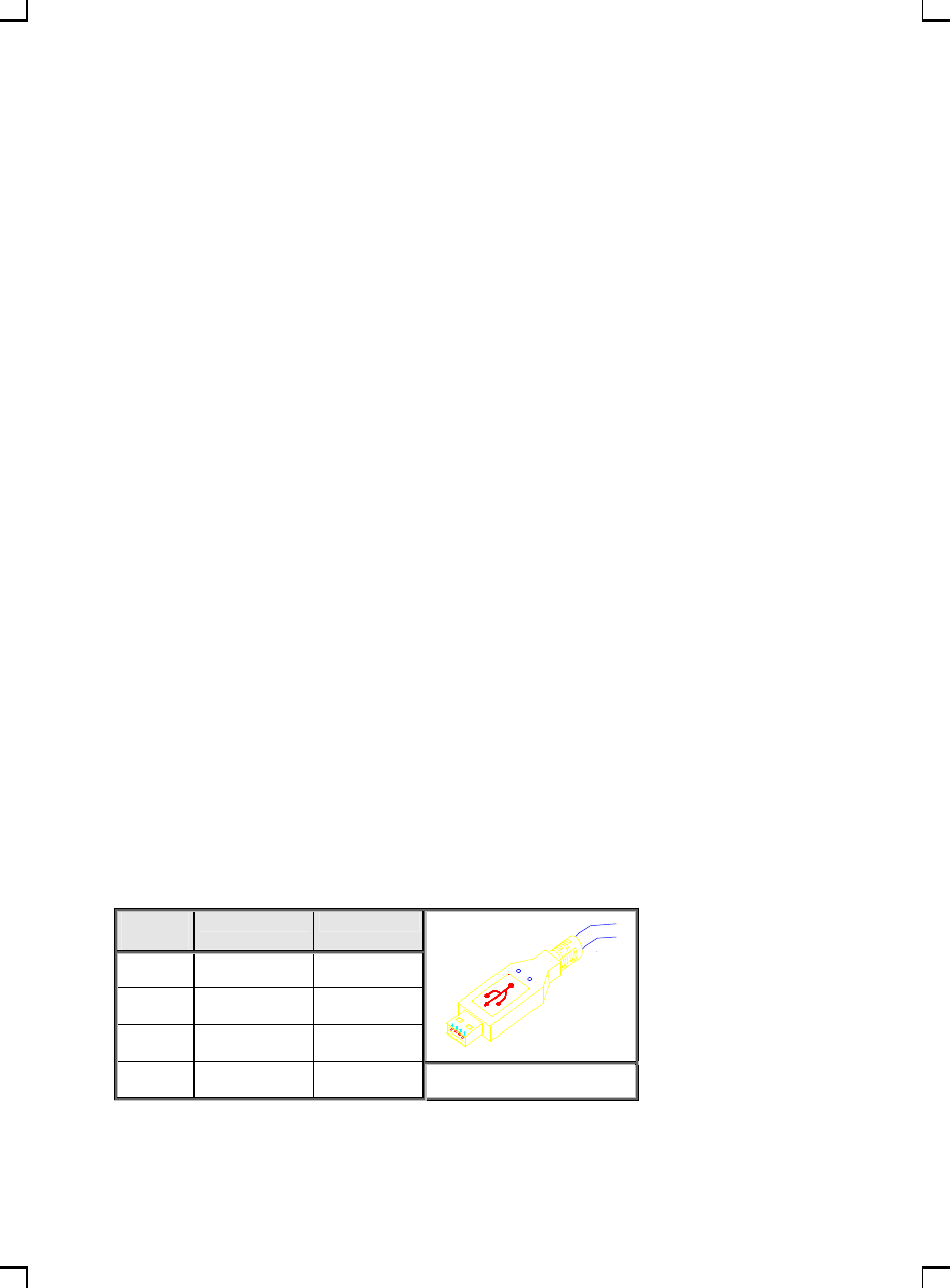
USB Cable, Plug Contact Numbering & Ports
USB keyboard has a cable for sub-channel device and a series A plug, which fully comply with the
USB specification 1.1.
Contact
Number
Signal Name
Comment
1 VCC Cable power
2 - Data
3 + Data
4 Ground Cable ground

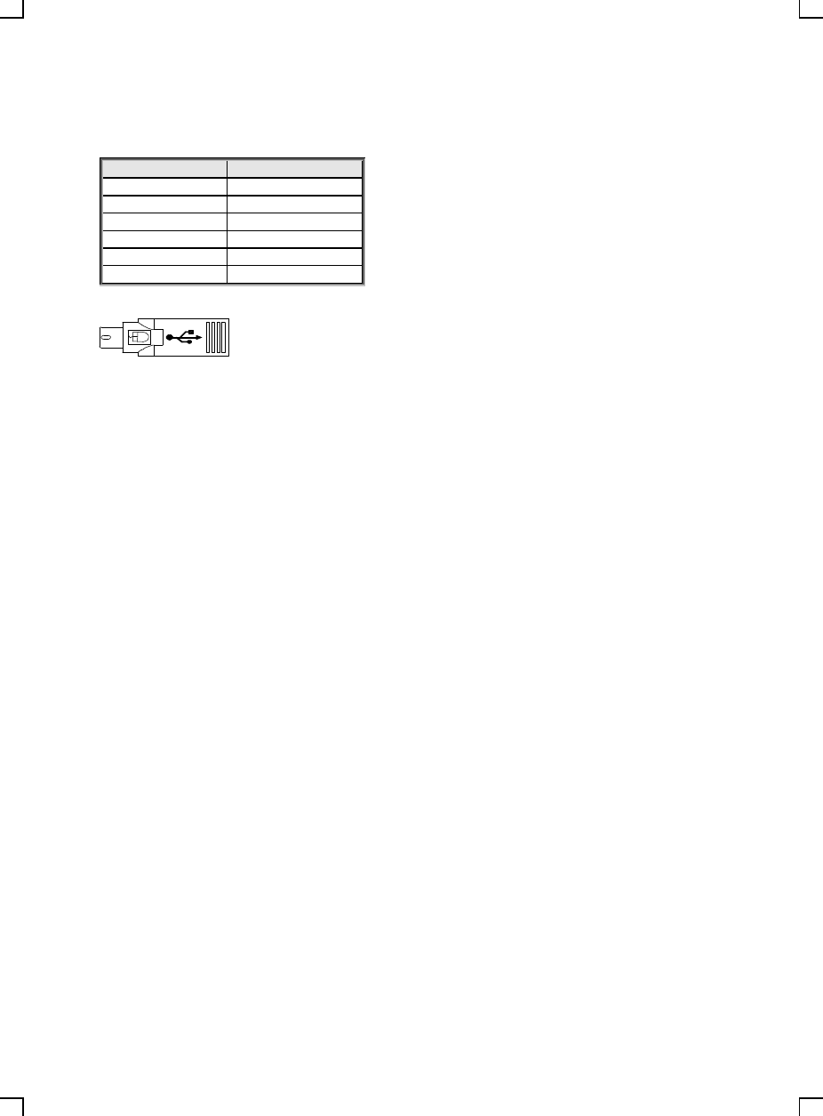
PS/2 Mouse Connector Contact Numbering & Port
Contact Number
Signal Name
1 Mouse data
2 Reserved
3 Ground
4 Reserved
5 + 5VDC
6 Mouse clock
FCC GUIDELINES
This equipment has been tested and found to comply with the limits for a Class B digital device, pursuant to Part 15
of the FCC Rules. These limits are designed to provide reasonable protection against harmful interference in a
residential installation. This equipment generates, uses and can radiate radio frequency energy and, if not installed
and used in accordance with the instructions may cause harmful interference to radio communications. However,
there is no guarantee that interference will not occur in a particular installation. If this equipment does cause harmful
interference to radio or television reception, which can be determined by turning the equipment off and on, the user is
encouraged to try to correct the interference by one or more of the following measures:
♦ Reorient or relocate the receiving antenna.
♦ Increase the separation between the equipment and receiver.
♦ Connect the equipment into an outlet on a circuit different from that to which the receiver is connected.
♦ Consult the dealer or an experienced radio/TV technician for help.
♦ Use only shielded cables to connect I/O devices to this equipment.
This device complies with Part 15 of the FCC Rules. Operation is subject to the following two conditions: (1) this
device may not cause harmful interference, (2) this device must accept any interference received, including
interference that may cause undesired operation.
NOTE: THE MANUFACTURER IS NOT RESPONSIBLE FOR ANY RADIO OR TV
INTERFERENCE
CAUSED BY UNAUTHORIZED MODIFICATIONS TO THIS EQUIPMENT.
SUCH MODIFICATIONS COULD VOID THE USER'S AUTHORITY TO OPERATE THE
EQUIPMENT.
Information to User:
F Any changes or modifications not expressly approved by the party responsible for compliance
could void the user’s authority to operate this equipment. Shielded interface cable, if any, must
be used in order to comply with emission limits.