Behringer Bcr2000 Users Manual B CONTROL FADER BCF2000/ROTARY
BCR2000 to the manual 53bba4a5-eb14-447a-bf72-1915d5152cfc
2015-02-04
: Behringer Behringer-Bcr2000-Users-Manual-362774 behringer-bcr2000-users-manual-362774 behringer pdf
Open the PDF directly: View PDF ![]() .
.
Page Count: 24
User Manual
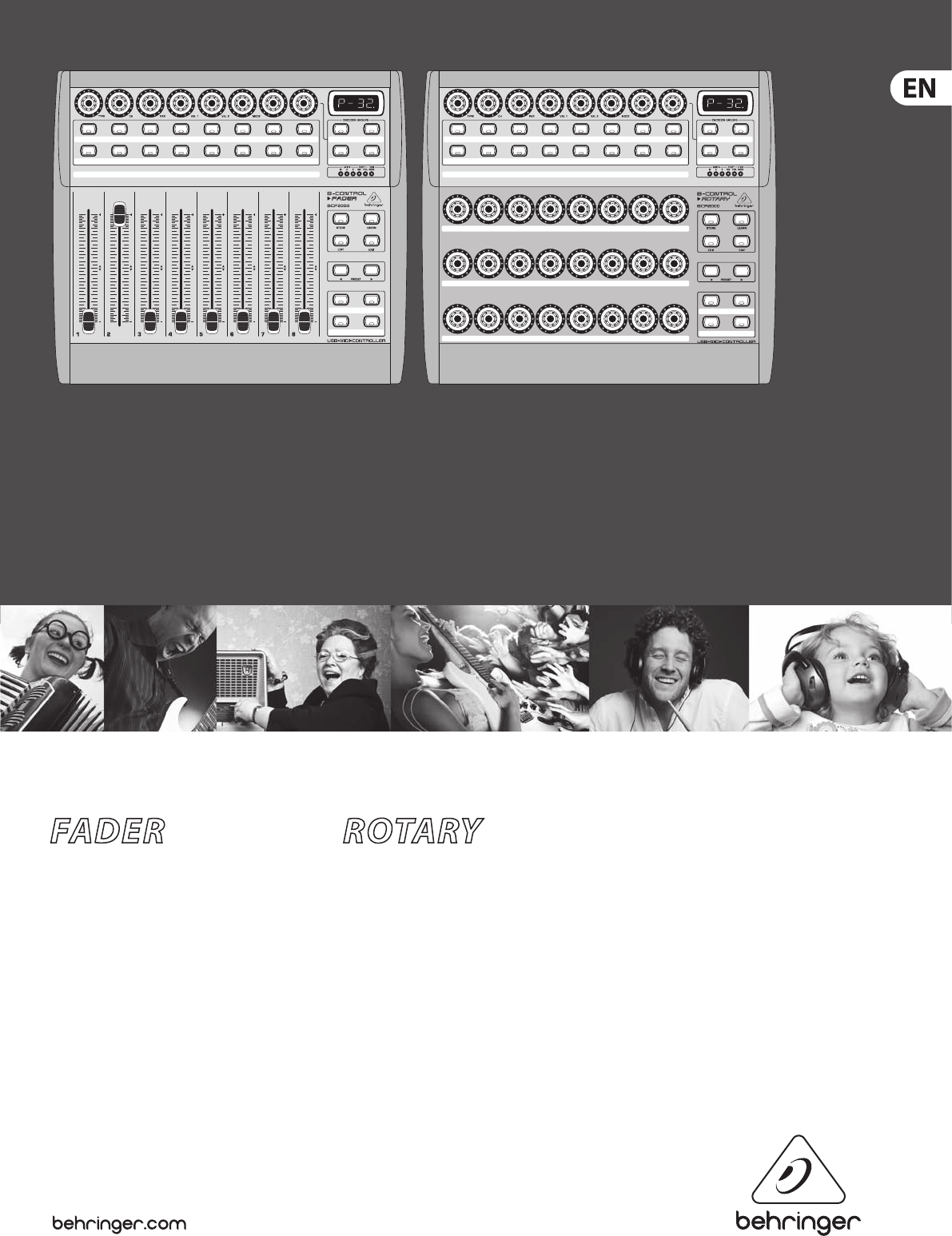
B-CONTROL
BCF2000/ BCR2000
FADER BCF2000
Total-Recall USB/MIDI Controller with 8 Motorized Faders
ROTARY BCR2000
Total-Recall USB/MIDI Controller with 32 Illuminated Rotary Encoders

2B-CONTROL FADER BCF2000/R OTARY BCR2000 User Manual
Thank you
Thank you very much for expressing your condence in BEHRINGER products by
purchasing the B-CONTROL.
Table of Contents
Thank you .......................................................................2
Important Safety Instructions ...................................... 3
Legal Disclaimer ............................................................. 3
Limited Warranty ........................................................... 3
1. Introduction .....................................................................................5
1.1 Before you get started ...................................................... 5
1.2 System requirements ........................................................ 5
1.3 Online registration ............................................................. 5
2. Introduction to MIDI ................................................. 5
2.1 MIDI control for beginners .............................................. 5
2.2 The MIDI standard .............................................................. 6
2.3 MIDI connections ............................................................... 6
2.4 The MIDI format .................................................................. 6
3. Control Elements and Connections ......................... 7
4. Operation ................................................................... 9
4.1 The operating modes ........................................................ 9
4.2 “Play” mode menu ........................................................... 14
4.3 Programming ..................................................................... 14
4.4 MIDI messages ................................................................... 17
4.5 Settings in the global setup menu ............................. 18
4.6 Additional functions ........................................................ 19
5. Appendix .................................................................. 20
6. Specications ........................................................... 22
3B-CONTROL FADER BCF2000/R OTARY BCR2000 User Manual
LEGAL DISCLAIMER
LIMITED WARRANTY
Terminals marked with this symbol carry
electrical current of su cient magnitude
to constitute risk of electric shock.
Use only high-quality professional speaker cables with
¼" TS or twist-locking plugs pre-installed. Allother
installation or modi cation should be performed only
by quali edpersonnel.
This symbol, wherever it appears,
alertsyou to the presence of uninsulated
dangerous voltage inside the
enclosure-voltage that may be su cient to constitute a
risk ofshock.
This symbol, wherever it appears,
alertsyou to important operating and
maintenance instructions in the
accompanying literature. Please read the manual.
Caution
To reduce the risk of electric shock, donot
remove the top cover (or the rear section).
No user serviceable parts inside. Refer servicing to
quali ed personnel.
Caution
To reduce the risk of re or electric shock,
do not expose this appliance to rain and
moisture. The apparatus shall not be exposed to dripping
or splashing liquids and no objects lled with liquids,
suchas vases, shall be placed on the apparatus.
Caution
These service instructions are for use
by quali ed service personnel only.
Toreduce the risk of electric shock do not perform any
servicing other than that contained in the operation
instructions. Repairs have to be performed by quali ed
servicepersonnel.
1. Read these instructions.
2. Keep these instructions.
3. Heed all warnings.
4. Follow all instructions.
5. Do not use this apparatus near water.
6. Clean only with dry cloth.
7. Do not block any ventilation openings. Install in
accordance with the manufacturer’s instructions.
8. Do not install near any heat sources such as
radiators, heat registers, stoves, or other apparatus
(including ampli ers) that produce heat.
9. Do not defeat the safety purpose of the polarized
or grounding-type plug. A polarized plug has two blades
with one wider than the other. A grounding-type plug
has two blades and a third grounding prong. The wide
blade or the third prong are provided for your safety. Ifthe
provided plug does not t into your outlet, consult an
electrician for replacement of the obsolete outlet.
10. Protect the power cord from being walked on or
pinched particularly at plugs, convenience receptacles,
and the point where they exit from the apparatus.
11. Use only attachments/accessories speci ed by
themanufacturer.
12. Use only with the
cart, stand, tripod, bracket,
or table speci ed by the
manufacturer, orsold with
the apparatus. When a cart
is used, use caution when
moving the cart/apparatus
combination to avoid
injury from tip-over.
13. Unplug this apparatus during lightning storms or
when unused for long periods of time.
14. Refer all servicing to quali ed service personnel.
Servicing is required when the apparatus has been
damaged in any way, such as power supply cord or plug
is damaged, liquid has been spilled or objects have fallen
into the apparatus, the apparatus has been exposed
to rain or moisture, does not operate normally, or has
beendropped.
15. The apparatus shall be connected to a MAINS socket
outlet with a protective earthing connection.
16. Where the MAINS plug or an appliance coupler is
used as the disconnect device, the disconnect device shall
remain readily operable.
TECHNICAL SPECIFICATIONS AND APPEARANCES
ARE SUBJECT TO CHANGE WITHOUT NOTICE AND
ACCURACY IS NOT GUARANTEED. BEHRINGER IS
PART OF THE MUSIC GROUP MUSICGROUP.COM.
ALL TRADEMARKS ARE THE PROPERTY OF THEIR
RESPECTIVE OWNERS. MUSICGROUP ACCEPTS NO
LIABILITY FOR ANY LOSS WHICH MAY BE SUFFERED
BY ANY PERSON WHO RELIES EITHER WHOLLY OR
IN PART UPON ANY DESCRIPTION, PHOTOGRAPH
OR STATEMENT CONTAINED HEREIN. COLORS AND
SPECIFICATIONS MAY VARY FROM ACTUAL PRODUCT.
MUSIC GROUP PRODUCTS ARE SOLD THROUGH
AUTHORIZED FULLFILLERS AND RESELLERS ONLY.
FULLFILLERSAND RESELLERS ARE NOT AGENTS OF
MUSICGROUP AND HAVE ABSOLUTELY NO AUTHORITY
TO BIND MUSICGROUP BY ANY EXPRESS OR IMPLIED
UNDERTAKING OR REPRESENTATION. THIS MANUAL
IS COPYRIGHTED. NO PART OF THIS MANUAL MAY
BE REPRODUCED OR TRANSMITTED IN ANY FORM
OR BY ANY MEANS, ELECTRONIC OR MECHANICAL,
INCLUDING PHOTOCOPYING AND RECORDING OF ANY
KIND, FOR ANY PURPOSE, WITHOUT THE EXPRESS
WRITTEN PERMISSION OF MUSICGROUPIPLTD.
ALL RIGHTS RESERVED.
© 2012 MUSICGroupIPLtd.
Trident Chambers, Wickhams Cay, P.O. Box 146,
Road Town, Tortola, British Virgin Islands
§ 1 Warranty
(1) This limited warranty is valid only if you purchased
the product from a MUSIC Group Authorized Reseller in
the country of purchase. A list of authorized resellers can
be found on BEHRINGER’s website behringer. com under
“Where to Buy”, or you can contact the MUSIC Group o
ce
closest to you.
(2) MUSICGroup* warrants the mechanical and
electronic components of this product to be free of defects
in material and workmanship if used under normal
operating conditions for a period of one (1) year from
the original date of purchase (see the Limited Warranty
terms in §4 below), unless a longer minimum warranty
period is mandated by applicable local laws. If the product
shows any defects within the speci ed warranty period
and that defect is not excluded under §4, MUSICGroup
shall, at its discretion, either replace or repair the product
using suitable new or reconditioned product or parts.
Incase MUSICGroup decides to replace the entire product,
thislimited warranty shall apply to the replacement
product for the remaining initial warranty period, i.e.,
one (1) year (or otherwise applicable minimum warranty
period) from the date of purchase of the original product.
(3) Upon validation of the warranty claim, the repaired
or replacement product will be returned to the user
freight prepaid by MUSICGroup.
(4) Warranty claims other than those indicated above
are expressly excluded.
PLEASE RETAIN YOUR SALES RECEIPT. IT IS YOUR PROOF
OF PURCHASE COVERING YOUR LIMITED WARRANTY.
THIS LIMITED WARRANTY IS VOID WITHOUT SUCH PROOF
OFPURCHASE.
§ 2 Online registration
Please do remember to register your new BEHRINGER
equipment right after your purchase at behringer. com
under “Support” and kindly read the terms and conditions
of our limited warranty carefully. Registeringyour
purchase and equipment with us helps us process
your repair claims quicker and more e ciently.
Thankyouforyour cooperation!
§ 3 Return materials authorization
(1) To obtain warranty service, please contact the
retailer from whom the equipment was purchased.
Should your MUSIC Group Authorized Reseller not be
located in your vicinity, you may contact the MUSICGroup
Authorized Ful ller for your country listed under
Important Safety
Instructions

4B-CONTROL FADER BCF2000/R OTARY BCR2000 User Manual
“Support” at behringer. com. Ifyour country is not
listed, please check if your problem can be dealt with
by our “OnlineSupport” which may also be found under
“Support” at behringer. com. Alternatively,please submit
an online warranty claim at behringer. com BEFORE
returning the product. All inquiries must be accompanied
by a description of the problem and the serial number
of the product. Afterverifying the product’s warranty
eligibility with the original sales receipt, MUSICGroup
will then issue a ReturnMaterials Authorization
(“RMA”)number.
(2) Subsequently, the product must be returned in
its original shipping carton, together with the return
authorization number to the address indicated by
MUSICGroup.
(3) Shipments without freight prepaid will not
beaccepted.
§ 4 Warranty Exclusions
(1) This limited warranty does not cover consumable
parts including, but not limited to, fuses and batteries.
Where applicable, MUSICGroup warrants the valves or
meters contained in the product to be free from defects
in material and workmanship for a period of ninety (90)
days from date of purchase.
(2) This limited warranty does not cover the product
if it has been electronically or mechanically modi ed
in any way. If the product needs to be modi ed or
adapted in order to comply with applicable technical
or safety standards on a national or local level, inany
country which is not the country for which the
product was originally developed and manufactured,
thismodi cation/adaptation shall not be considered a
defect in materials or workmanship. Thislimited warranty
does not cover any such modi cation/adaptation,
regardless of whether it was carried out properly or not.
Under the terms of this limited warranty, MUSICGroup
shall not be held responsible for any cost resulting from
such a modi cation/adaptation.
(3) This limited warranty covers only the product
hardware. It does not cover technical assistance for
hardware or software usage and it does not cover
any software products whether or not contained in
the product. Any such software is provided “AS IS”
unless expressly provided for in any enclosed software
limitedwarranty.
(4) This limited warranty is invalid if the
factory- appliedserial number has been altered or
removed from theproduct.
(5) Free inspections and maintenance/repair work
are expressly excluded from this limited warranty,
inparticular, if caused by improper handling of the
product by the user. This also applies to defects caused
by normal wear and tear, in particular, of faders,
crossfaders, potentiometers, keys/buttons, guitar strings,
illuminantsand similar parts.
(6) Damage/defects caused by the following conditions
are not covered by this limited warranty:
• improper handling, neglect or failure to operate the
unit in compliance with the instructions given in
BEHRINGER user or service manuals;
• connection or operation of the unit in any way
that does not comply with the technical or safety
regulations applicable in the country where the
product is used;
• damage/defects caused by acts of God/Nature
(accident, re, ood, etc) or any other condition that
is beyond the control of MUSICGroup.
(7) Any repair or opening of the unit carried out by
unauthorized personnel (user included) will void the
limitedwarranty.
(8) If an inspection of the product by MUSICGroup
shows that the defect in question is not covered by the
limited warranty, the inspection costs are payable by
thecustomer.
(9) Products which do not meet the terms of this
limited warranty will be repaired exclusively at the buyer’s
expense. MUSICGroup or its authorized service center will
inform the buyer of any such circumstance. If the buyer
fails to submit a written repair order within 6 weeks after
noti cation, MUSICGroup will return the unit C.O.D. with
a separate invoice for freight and packing. Such costs will
also be invoiced separately when the buyer has sent in a
written repair order.
(10) MUSIC Group Authorized Resellers do not sell new
products directly in online auctions. Purchasesmade
through an online auction are on a “buyer beware” basis.
Online auction con rmations or sales receipts are not
accepted for warranty veri cation and MUSICGroup will
not repair or replace any product purchased through an
online auction.
§ 5 Warranty transferability
This limited warranty is extended exclusively to the
original buyer (customer of authorized reseller) andis
not transferable to anyone who may subsequently
purchase this product. No other person (reseller,etc.)
shallbe entitled to give any warranty promise on behalf
of MUSICGroup.
§ 6 Claim for damage
Subject only to the operation of mandatory applicable
local laws, MUSICGroup shall have no liability to the buyer
under this warranty for any consequential or indirect
loss or damage of any kind. In no event shall the liability
of MUSICGroup under this limited warranty exceed the
invoiced value of the product.
§ 7 Limitation of liability
This limited warranty is the complete and exclusive
warranty between you and MUSICGroup. It supersedes
all other written or oral communications related to this
product. MUSICGroup provides no other warranties for
this product.
§ 8 Other warranty rights and
nationallaw
(1) This limited warranty does not exclude or limit the
buyer’s statutory rights as a consumer in any way.
(2) The limited warranty regulations mentioned herein
are applicable unless they constitute an infringement of
applicable mandatory local laws.
(3)
This warranty does not detract from the seller’s
obligations in regard to any lack of conformity of the
product and any hidden defect.
§ 9 Amendment
Warranty service conditions are subject to change without
notice. For the latest warranty terms and conditions
and additional information regarding MUSICGroup’s
limited warranty, please see complete details online at
behringer. com.
* MUSICGroup Macao Commercial O shore Limited of
RuedePequim No. 202-A, Macau Finance Centre 9/J, Macau,
including all MUSICGroup companies

5B-CONTROL FADER BCF2000/R OTARY BCR2000 User Manual
1. Introduction
The B-CONTROL is an extremely exible control surface suitable for a wide array
of applications. Regardless of whether you want to intuitively control your
sequencer software with mixers, plug-ins and virtual instruments, or if you wish
to use its broad MIDI functions for controlling rack synthesizers, general MIDI
sound generators or eect processors, the B-CONTROL oers you tremendous
ease of use that leaves no wishes open.
To ensure the highest possible operating safety, our equipment is manufactured
according to the highest quality standards in the audio industry.
Additionally, we produce our equipment adhering to the ISO9000 certied
management system.
◊ The following user’s manual is intended to familiarize you with the
unit’s control elements, so that you can master all the functions.
After having thoroughly read the user’s manual, store it at a safe place
for future reference.
1.1 Before you get started
1.1.1 Shipment
The B-CONTROL was carefully packed at the assembly plant to assure
secure transport. Should the condition of the cardboard box suggest that damage
may have taken place, please inspect the unit immediately and look for physical
indications of damage.
◊ Damaged equipment should NEVER be sent directly to us. Please inform
the dealer from whom you acquired the unit immediately as well as
the transportation company from which you took delivery of the unit.
Otherwise, all claims for replacement / repair may be rendered invalid.
◊ To assure optimal protection of your B-CONTROL during use or
transport, we recommend utilizing a carrying case.
◊ Please always use the original packaging to avoid damage due to
storage or shipping.
◊ Never let unsupervised children play with the B-CONTROL or with
its packaging.
◊ Please dispose of all packaging materials in an environmentally-
friendly fashion.
1.1.2 Initial operation
Please make sure the unit is provided with sucient ventilation, and never place
the B-CONTROL on top of an amplier or in the vicinity of a heater to avoid the
risk of overheating.
A power supply unit which meets the necessary safety requirements is enclosed
for connecting the B-CONTROL to the mains.
1.1.3 Warranty
Please take a few minutes and send us the completely lled out warranty
card within 14 days of the date of purchase to assure unproblematic warranty
processing in the future. You may also register online at behringer.com.
The serial number needed for the registration is located at the top of the unit.
Failure to register your product may void future warranty claims.
1.2 System requirements
For USB operation:
Up-to-date Windows PC or MAC with a USB connection
◊ The B-CONTROL supports WINDOWS XP and MAC OS X “USB MIDI
compatibility”. Soon, you will be able to download drivers for
other operating systems, for multi unit support, new presets
as well as a WINDOWS editor software free of charge. Just click
behringer.com to get it for free.
◊ The BCF2000 / BCR2000 can also be operated stand-alone without a
PC as a pure MIDI controller. Software control via MIDI is also possible,
provided your computer has a MIDI interface.
1.3 Online registration
Please register your new BEHRINGER equipment right after your purchase
by visiting http://behringer.com and read the terms and conditions of our
warranty carefully.
Should your BEHRINGER product malfunction, it is our intention to have it
repaired as quickly as possible. To arrange for warranty service, please contact
the BEHRINGER retailer from whom the equipment was purchased. Should your
BEHRINGER dealer not be located in your vicinity, you may directly contact
one of our subsidiaries. Corresponding contact information is included in the
original equipment packaging (Global Contact Information/European Contact
Information). Should your country not be listed, please contact the distributor
nearest you. A list of distributors can be found in the support area of our website
(http://behringer.com).
Registering your purchase and equipment with us helps us process your repair
claims more quickly and eciently.
Thank you for your cooperation!
2. Introduction to MIDI
2.1 MIDI control for beginners
Application possibilities for both B-CONTROL models, the BCF2000 and
the BCR2000, are truly wide-ranging. We’ll start with a couple of general
explanations and examples that should quickly let you get a good understanding
of MIDI basics.
What exactly does the B-CONTROL do?
Simply put, this a remote control for all kinds of MIDI equipment. Using the faders
(BCF2000 only), encoders (innitely variable rotary controls) and keys, an entire
array of control functions can be performed. Adjusting these parameters, you can
control various functions of external (hardware or software) equipment in real
time. For example, countless software mixers, sound generators or eects can
be remotely controlled. With these software applications, you are dealing with
simulations of “real” equipment in your computer, whereby they are visually
represented on the computer screen, while the computer takes over the function
of replicating their respective functions.
And how does it work?
You can assign particular MIDI data to each control element on the B-CONTROL;
for example, you can assign the so-called “MIDI-Controller 7” (CC 07) that adjusts
the volume of a MIDI device to one of the controls on your BCF2000 / BCR2000.
If you move / turn the corresponding control on your B-CONTROL, you can hear
how the volume on the receiving MIDI device also changes (provided it is also
connected to an audio output). Keep the following in mind:
◊ MIDI data is only control data and contains no audio information!

6B-CONTROL FADER BCF2000/R OTARY BCR2000 User Manual
What settings do I have to make? Where? How?
Often, you can assign MIDI control data numbers, the so-called control change
or CC numbers, to individual MIDI parameters. That’s particularly the case with
music software such as software sequencers, mixers and sound generators as
well as the so-called “plug-ins” (eect units or sound generators integrated
into the software).
Basically, you have 2 options:
You either set the desired control numbers at the B-CONTROL and transmit
them to the software you are controlling, or you can set the desired control data
directly on your MIDI device and let the B-CONTROL receive the information about
number assignment using the LEARN procedure.
Example:
On a software synthesizer, you want to control lter frequency, lter resonance
and volume using the MIDI controllers 5, 6 and 7.
To receive MIDI data, you’ll need to perform the following settings on your
software synthesizer:
• set lter frequency to CC 05
• set lter resonance to CC 06 (receive)
• set volume to CC 07 (receive)
To get detailed information on how to assign them, please refer to chapter
4.3.2 “Programming in the EDIT mode” on page 13.
Now, dene in the B-CONTROL the control elements that will control these
3 parameters. You can either use the Learn function if the software synthesizer
gives you the option to send its CC data via MIDI, or you can implement the
following settings manually:
• Assign the push encoder 1 CC 05 to lter frequency control via dial rotation
• Assign the push encoder 2 CC 06 to lter resonance control via dial rotation
• Assign the push encoder 3 CC 07 to volume control via dial rotation
How do I wire the B-CONTROL?
Several classic examples can be found in the explanations of dierent operating
modes (see chapter 4.1 “The Operating Modes”). Basically, the following applies:
• If you want to control hardware MIDI equipment, use the MIDI connectors
• To control software MIDI equipment, you can either use the MIDI connectors
on your B-CONTROL – provided your computer has a MIDI interface –
or you can use a USB connection
• To remotely control both hardware and software equipment,
several combination modes are available. These are explained in chapter 4.1
What kinds of equipment can I control with the
B-CONTROL?
You can basically control any device supporting the MIDI format. Both hardware
and software MIDI devices are controlled exactly the same. The only dierence is
in the wiring.
Here are a couple of suggestions on how you can use
your B-CONTROL:
• Editing sound parameters of (virtual) synthesizers, sound samplers,
GM/GS/XG sound generators
• Controlling parameters on eects equipment / software plug-ins such as
eects processors, reverbs, compressors, equalizers etc.
• Remotely controlling software mixers (volume, panorama, equalizers etc.)
• Remotely controlling transport functions (playback, forward, stop etc.)
on sequencers, hard disk recorders, drum computers etc.
• Using BCF2000 faders as drawbar control for virtual or digital
organ expanders
• Controlling MIDI-enabled lighting equipment
• Live control of volume and sound parameters on expanders
• Triggering (i.e. playing live) short samples, drum loops, shouts, eects etc.
• Remotely controlling groove boxes, step sequencers, MIDI generators
(such as arpeggiators etc.), DJ software and other “live” software
• Program changes and volume control on sound generators (just like on a
master keyboard)
• Likewise, applicable to band keyboardists, solo entertainers, organists,
electronic music performers, DJs, sound engineers, home / project studio
owners, theater technicians etc.
2.2 The MIDI standard
The MIDI standard (Musical Instruments Digital Interface) was developed in
the early ’80s to make communication between equipment from dierent
manufacturers possible. Over the years, the MIDI interface has become hugely
popular; it has become a matter of fact that complete studios can be connected
via MIDI.
At the center of any such network is at least one computer that controls
peripheral equipment. You can use the B-CONTROL in such a studio to control
your sequencer or other software tools running on your computer (e.g. software
mixers, VST instruments, eect plug-ins). But even if you don’t use a computer,
you can use the B-CONTROL as a central control surface in your studio for
comfortably editing your rack synthesizers, GM/GS/XG sound generators and
eects equipment.
2.3 MIDI connections
The MIDI connections in the back of your B-CONTROL feature the standard 5-pin
DIN connectors. You will require MIDI cables to connect your B-CONTROL to other
MIDI equipment. In general, commercially available ready-to-use cables can and
should be used. Their length should not exceed 15 m (50 ft.).
MIDI IN: Used for receiving MIDI data (parameter feedback, SysEx data),
or to mix MIDI signals with the B-CONTROL signals (merge function).
MIDI OUT A / B: Data for controlling other MIDI equipment can be sent through
the MIDI outputs.
◊ The B-CONTROL has two MIDI outputs. MIDI OUT B can be configured
as MIDI Thru, so that the incoming data at MIDI IN can be passed
through unaffected.
2.4 The MIDI format
Although your B-CONTROL is very easy to use, it still makes sense to review
some information about this data format. Each MIDI command, also called
message, consists of a status byte and up to two data bytes. The status byte
denes the command type, and the data bytes contain the corresponding values.
Dierent types of MIDI messages used by the B-CONTROL are explained next:
Note messages:
Among keyboard hotshots, Note On and Note O messages are among the
essential MIDI messages. Playing MIDI instruments from a master keyboard
or computer is only possible with these messages. The B-CONTROL can also
send Note Messages; however, this is not absolutely necessary to play music.
This way, note events are also used to trigger drumloops or individual notes from
a sampler. Many eects processors also allow rhythmic entering of delay times or
song tempos with note commands.

7B-CONTROL FADER BCF2000/R OTARY BCR2000 User Manual
Note On and Note O messages have the following
data format:
Status Byte Data Byte 1 Data Byte 2
Note O &8n (n = channel #) Note # Velocity
Note On &9n (n = channel #) Note # Velocity
Table 2.1: Data format of Note On and Note O messages
The value range for channel numbers is between 1 and 16; for data bytes it
is 0 to 127. Even though Note O messages are not really used by keyboarders
anymore, the B-CONTROLs support sending this status information.
Velocity corresponds to the key pressure, and therefore to the volume of a
touch-sensitive keyboard (piano). Since the B-CONTROL does not feature
touch-sensitive keys, the velocity value is transmitted with a xed value that can
be set during programming.
◊ A note command can only be assigned to keys, footswitches and push
functions of the encoder.
Control Change (CC):
Control Change Messages are some of the most “powerful” MIDI messages.
Using them, a vast number of parameters and functions can be recalled and
automated. Individual control elements (faders, rotary dials, keys etc.) can be
assigned to CC messages on your B-CONTROL. Because not only keys but also
faders and rotary dials can be used, control values can be controlled in real time
either statically or dynamically. A list with the standard controller numbers can
be found in this user manual’s appendix.
NRPN:
Additionally, controllers that have no standardized assignment can also be
used, and can therefore be assigned according to no predetermined rule.
These controllers are called NRPNs (Non-Registered Parameter Numbers).
NRPNs are further subdivided into MSB (Most Signicant Byte) and LSB
(Least Signicant Byte) in order to achieve a higher resolution. A lower resolution
is particularly easy to observe during fader movement of a mixer, in which 7-bit
(= 128 values) jumps in the signal level can be heard. By subdividing NRPNs
into MSB and LSB, you can achieve 14-bit resolution of faders and rotary dials,
which means that the movement of a fader is divided into more than 16,000
steps (214)! In addition to NRPNs, there are also RPNs (Registered Parameter
Numbers). RPN commands are dened as GM (general MIDI), GS (Roland) and
XG (Yamaha) MIDI standards.
Pitch Bend:
The pitch-bend wheel of a keyboard is used for tone modulation and has its own
commands in the MIDI format.
After Touch:
MIDI keyboards featuring After Touch can respond to varying key pressure even
after you release the key (i.e. after the keystroke is over) and can send this data
via MIDI. This function either reacts key-specic (key pressure) or it reacts to all
notes at the same time (channel pressure).
MIDI Machine Control (MMC):
With MIDI Machine Control, you can assign transport functions of a sequencer or
drum computer (e.g. start, stop, FFW / RWD) and locator points to individual keys
with a permanently adjustable time position (locate, punch in / out points).
Program Change Messages and MIDI Bank Select:
Program change messages are used to recall programs / presets in MIDI devices
connected to your B-CONTROL. 128 program numbers can be recalled. For devices
with more than 128 presets, use the bank select function, which lets you select a
storage bank before sending a program change.
Running Status:
Because the MIDI interface is a serial data transmission format (meaning that
its data is transmitted as a succession of individual data segments), it became
apparent very quickly that it may not be fast enough. To avoid perceptible delays
in the output of MIDI data, Running Status was designed. It suppresses the
transmission of the status byte when the same MIDI messages are transmitted
in succession. This means that, for example, during a continuous change of
the data byte of a controller (e.g. volume), the status byte is only sent once.
The only thing that is transmitted are the changes in the data byte. This goes on
until another status byte is sent. 8 bits are saved for each message sent.
SysEx Dump:
System-Exclusive data refer to a function that makes transmission of nonspecic
data via MIDI possible. This is often used for reading out memory contents and
storing them externally.
The status byte notes the data type (SysEx); the rst three data bytes are a
manufacturer ID, so that when you have a large MIDI network, you can still “talk”
to the correct MIDI device.
To make using several identical B-CONTROLs at the same time possible, you can
assign a device number (device ID) in the global setup menu to each B-CONTROL,
which assures that only the correct device receives the data intended for it.
3. Control Elements and
Connections
In this chapter, we will describe various control elements of your B-CONTROL.
All controls and connectors are explained in detail, and we’ll give you useful tips
on how to use them.
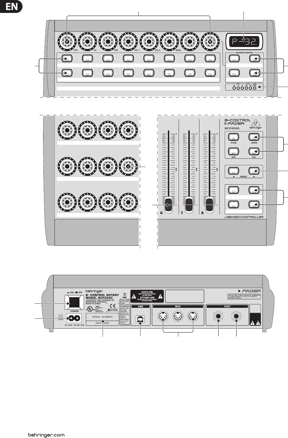
(1) The 8 innitely variable PUSH ENCODERS are used to send MIDI data.
They have two functions (turn and press) that can be assigned to dierent
MIDI commands.
(2) Each of these 16 KEYS can send one MIDI command.
(3) The four-digit LED display indicates the current operating software version
briey during startup. After that, it shows the selected preset number.
When in play mode, activating one of the control elements indicates
value changes on the LED in real time. When in programming mode,
it indicates the type of MIDI commands, program / channel numbers and
parameter values.
(4) Using the ENCODER GROUP keys, four so-called encoder groups per preset
can be recalled, so that eight PUSH encoders for a total of 64 dierent MIDI
functions are at your disposal.
(5) These LEDs indicate the following:
MIDI IN, OUT A and OUT B illuminate if MIDI data ows through the
respective connectors.
USB Mode illuminates if a USB connection to a computer is active
(your computer must be on).
The FOOT SW LEDs illuminate if the footswitch is pressed.
FOOT CTRL LED (BCF2000 only) illuminates when the footcontroller is
actuated (MIDI data is sent).
8B-CONTROL FADER BCF2000/R OTARY BCR2000 User Manual
(5)
(10)
(3)(1)
(6)
(8)
(9)
(7)
(4)
(2)
BCR2000 BCF2000
Fig. 3.1: The control surface of the B-CONTROLs
OUT A INOUT B
/
THRU CONTROLLER SWITCH
CAUTION
TO REDUCE T HE RISK OF EL ECTRIC S HOCK
DO NOT REM OVE COV ER. NO USER -SERV ICEAB LE PARTS
INSIDE: R EFER SERV ICING TO Q UALIFIED P ERSONNEL .
CAUTION
TO REDUCE T HE RISK OF FIR E OR ELECT RIC SHOCK
DO
NOT EX POSE TH IS EQUIPMEN T TO RAIN O R MOISTUR E.
USB•MIDI•FADER•CONTROLLER
B
–
CONTROL
BCF2000
型 号:
BCF2000
MIDI控制器
制造商:
Behringer
Holdings (Pte)
Ltd
中国制造
警告
电击危险
请勿打开机盖
(15)
(13)
(16) (17) (12) (11)
(14)
Fig.3.2: The back of the BCF2000 (control elements (13) to (17) coincide with the BCR2000)
(6) Permanently xed functions are assigned to this key section:
STORE saves presets.
LEARN gets you to the LEARN mode.
EDIT gets you to the EDIT mode.
Using the EXIT key, you exit a programming level (edit mode / global setup).
Use it also to cancel a store or copy procedure.
(7) The eight 100-mm faders of the BCF2000 are freely assignable for controlling
MIDI commands. They are motorized, so they automatically slide into the
predetermined position when you switch to another preset. If the software
you are controlling or the MIDI device to which your B-CONTROL is connected
support parameter feedback, the fader positions change automatically.
(8) Using the PRESET keys, 32 presets can be recalled. The preset number is
shown in the display.
(9) These four keys can be assigned to any MIDI command of your choice.
9B-CONTROL FADER BCF2000/R OTARY BCR2000 User Manual
(10) The 24 innitely variable rotary controls (encoders) of the BCR2000 can
be programmed to send MIDI control commands. The LED circle show the
current value.
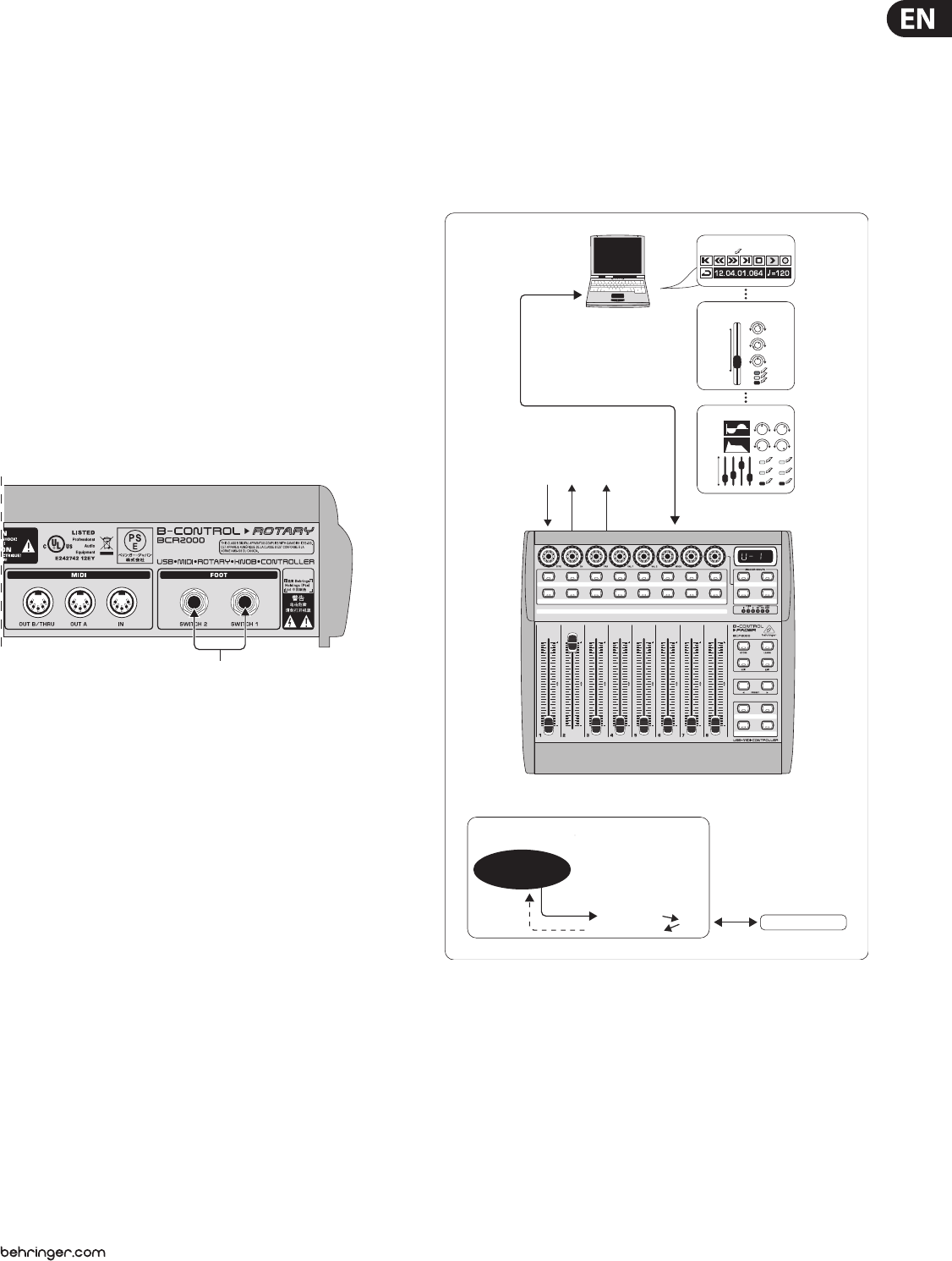
(11) These are the SWITCH connectors for connecting a footswitch.
Its polarity is automatically detected. On the BCR2000, the rst connector
(SWITCH 1) can also be used to connect a double footswitch with stereo
jacks. In this case, SWITCH 2 must remain unused.
(12) CONTROLLER connector (BCF2000 only). Here, you can connect an
expression pedal that can be used for controlling assignable MIDI data.
(13) The POWER switch turns your B-CONTROL on. The POWER switch should
always be in its “O” position when connecting the unit to the mains.
◊ Please keep in mind: The POWER switch does not fully disconnect
your B-CONTROL from the mains. Always unplug the power cord
from the mains if you don’t intend to use your B-CONTROL for longer
periods of time.
(14) The connection to the mains is established using a standard
connectionsocket. A matching cable is included in the shipment.
(15) SERIAL NUMBER. Please take the time to ll out and return the warranty
card within 14 days after the date of purchase to benet from our extended
warranty. The serial number is located on the top side of your REV2496.
You can also register online at behringer.com.
型 号:
BCR2000
MIDI控制器
(11)
Fig. 3.3: The footswitch connectors on the BCR2000
(16) The USB connector is used for connecting to a computer with a compatible
USB input.
(17) These are the MIDI connectors of your B-CONTROL. Depending on the
operating mode, MIDI OUT B doubles as MIDI THRU.
4. Operation
4.1 The operating modes
Depending on how you want to use your B-CONTROL, you should rst select an
operating mode.
You can use it as a pure USB controller for your computer applications
(software mixers, sequencers, soft synths, VST-eects etc.), as a stand-alone MIDI
controller, or as a combination of both with dierent MIDI interface conguration
possibilities. Here is how you select an operating mode:
• Keep the EDIT key pressed, and press the STORE key at the same time
• You are now in the global setup menu and you can let go of both keys
• Now, select an operating mode by turning the PUSH encoder 1.
You can select USB modes U-1 to U-4 and stand-alone modes S-1 to S-4.
The modes are described in detail in chapter 4.1.1 and further, and examples
about their use are also given there. Please see also chapter 4.3.3
• To exit global setup, please press the EXIT key
◊ The settings made in the global setup menu are automatically stored
and do not have to be separately saved.
The USB connection is briey interrupted if you switch within a USB mode,
or when you switch from a USB mode to a stand-alone mode and vice versa.
If a USB connection is made or lost while your B-CONTROL is on, the selected
operating mode is retained.
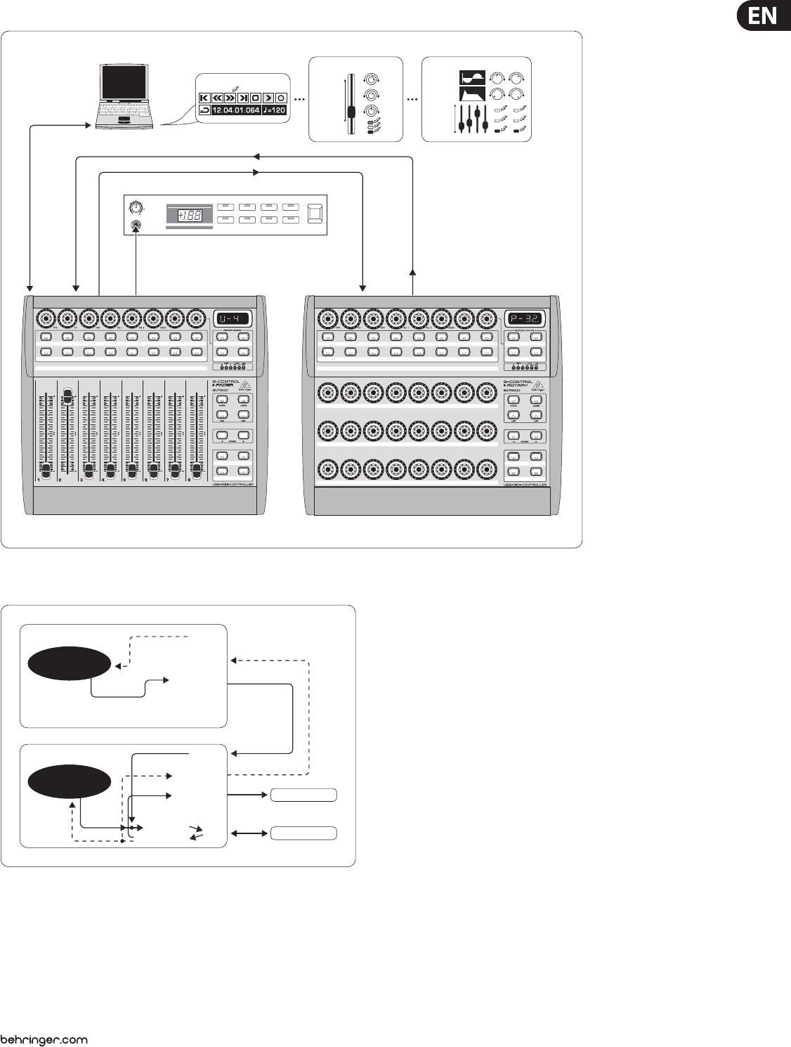
4.1.1 USB modes
USB mode U-1:
BCF/BCR2000
Parameter
Feedback to Computer
from Computer USB
MIDI IN
MIDI OUT A
MIDI OUT B/
THRU
B-CONTROL
MIDI Data Send
Computer
Software Sequencer
push
Software Mixer
move/
fade
turn
push
Software Synthesizer
move/
fade
turn
push
OUT A OUT B/THRU
MIDI IN
Fig. 4.1: Routing and use in USB mode 1
In USB mode 1, the B-CONTROL is connected to your PC by using a USB cable.
It sends MIDI data and receives parameter feedback from the computer,
provided that the music software you are controlling supports these functions.
This way, current parameter values can be shown on the LED, or can be indicated
by the fader position.
All MIDI ports of the B-CONTROL are o. This mode is optimal for controlling
software tools (mixers, sequencers, synths, VST-eects etc.) if you don’t need
any additional MIDI ports. This mode is also very useful if you are already using
other multi-channel MIDI interfaces on your computer and can’t address any
additional ones.

10 B-CONTROL FADER BCF2000/R OTARY BCR2000 User Manual
USB-Mode U-2:
Sampler
MIDI Keyboard
MIDI-Expander B
BCF/BCR2000
Parameter
Feedback to Computer
from Computer USB
MIDI IN
MIDI OUT A
MIDI OUT B/
THRU
B-CONTROL
MIDI Data Send
Computer
VOLUME MUTE DEMO FILTER LEVEL
PROG TYPE COMBI PLAY POWER
PHONES
MIDI IN OUT A USB
OUT B/THRU
MIDI-Expander
Sampler
MIDI Keyboard
Software Sequencer
push
Software Mixer
move/
fade
turn
push
Software Synthesizer
move/
fade
turn
push
MIDI IN
MIDI IN
MIDI OUT
Fig. 4.2: Routing and use in USB mode 2
Your B-CONTROL sends MIDI data to the computer and receives parameter
feedback, provided that the software you are controlling supports this function.
MIDI IN and OUT A are available as a 16-channel MIDI interface for your computer.
OUT B functions as MIDI THRU and forwards MIDI IN data unchanged. OUT B is
not accessible from the computer, and doesn’t send any control data from the
B-CONTROL. This mode is ideal for applications in which you control music
software on your computer and at the same time need a USB MIDI interface with
one IN and one OUT. Additionally, a MIDI keyboard can be tapped into at the MIDI
THRU (OUT B) connector. This way, you can use a master keyboard to import your
arrangements into the sequencer, or to play back software synths. OUT A controls
a hardware sampler, while a MIDI expander (sound generator without a
keyboard; e.g. a rack synthesizer or a pure preset unit), an eects processor or
similar can be connected at OUT B, whereby it is directly controlled only from the
keyboard or is controlled only via program changes.
USB-Mode U-3:
VOLUME MUTE DEMO FILTER LEVEL
PROG TYPE COMBI PLAY POWER
PHONES
VOLUME MUTE DEMO FILTER LEVEL
PROG TYPE COMBI PLAY POWER
PHONES
MIDI IN OUT A USBOUT B/THRU
MIDI-Expander B
MIDI-Expander A
MIDI Keyboard
Software Sequencer
push
Software Mixer
move/
fade
turn
push
Software Synthesizer
move/
fade
turn
push
MIDI-Expander A
MIDI Keyboard
MIDI-Expander B
BCF/BCR2000
Parameter
Feedback to Computer
from Computer USB
MIDI IN
MIDI OUT A
MIDI OUT B/
THRU
B-CONTROL
MIDI Data Send
Computer
MIDI IN
MIDI IN
MIDI OUT
Fig. 4.3: Routing and use in USB mode 3
This is surely the most often used “standard mode” with computer applications.
This setting is optimal for controlling software while all MIDI connectors are
used as a USB-MIDI interface for the computer. With this function, there are
16 input channels and 32 output channels available to your music software
(IN and OUT A + OUT B).
The B-CONTROL transmits its data via USB to the computer. The availability
of parameter feedback from the computer to the B-CONTROL depends on the
software your are controlling. MIDI expanders can not be directly accessed from
the keyboard in this operating mode. This operating mode is only used to import
MIDI tracks into the sequencer.
11 B-CONTROL FADER BCF2000/R OTARY BCR2000 User Manual
USB-Mode U-4 (expanded):
Unit 1
USB
MIDI IN MIDI IN
MIDI IN
OUT A OUT B/THRU OUT B/THRU
MIDI-Expander
Unit 2
Software Sequencer
push
Software Synthesizer
move/fade
turn
push
Software Mixer
move/fade
turn
push
VOLUME MUTE DEMO FILTER LEVEL
PROG TYPE COMBI PLAY POWER
PHONES
Fig. 4.4: Application in USB mode 4 (expanded)
BCF/BCR2000
BCF/BCR2000
Param. Feedb.
Parameter
Feedback
UNIT 2
MIDI Data Send
MIDI IN
MIDI IN
MIDI-Expander
MIDI OUT A
MIDI OUT A
MIDI OUT B/
THRU
MIDI OUT B/
THRU
USB
USB
Merge
to Computer
from Computer
UNIT 1
MIDI Data Send
Computer
Fig. 4.5: Routing in USB mode 4
This operating mode should be selected if you want to couple two B-CONTROLs
(e.g. 1x BCF2000 & 1x BCR2000) to control your software using both B-CONTROLS
through a common USB port. Additionally, MIDI OUT B of the rst controller
(unit 1) can be used from the computer as a 16-channel MIDI output. The data
of both B-CONTROLs is mixed and is sent to the host computer via USB.
Select stand-alone mode 3 for the second unit (unit 2).
4.1.2 Stand-alone modes
The stand-alone modes come into play when the B-CONTROL is not used as
a USB-controller for controlling PC applications but as a pure MIDI controller.
With all stand-alone modes, all MIDI connectors can be used simultaneously,
and these modes dier only in how the data is transmitted on the MIDI outputs.
Of course, not only sound generators can be remotely controlled (as shown in the
illustrations) but also eects processors, groove boxes, hardware sequencers,
lighting equipment, compact studios, portable keyboards, e-pianos etc. –
basically any equipment with a MIDI input. This can also be your computer with
its own MIDI interface. The USB connector can not be used while your B-CONTROL
is in one of the stand-alone modes. A merge function that makes mixing MIDI
data from two dierent sources to one output possible is active at output A in
stand-alone modes S-1 to S-3.
12 B-CONTROL FADER BCF2000/R OTARY BCR2000 User Manual
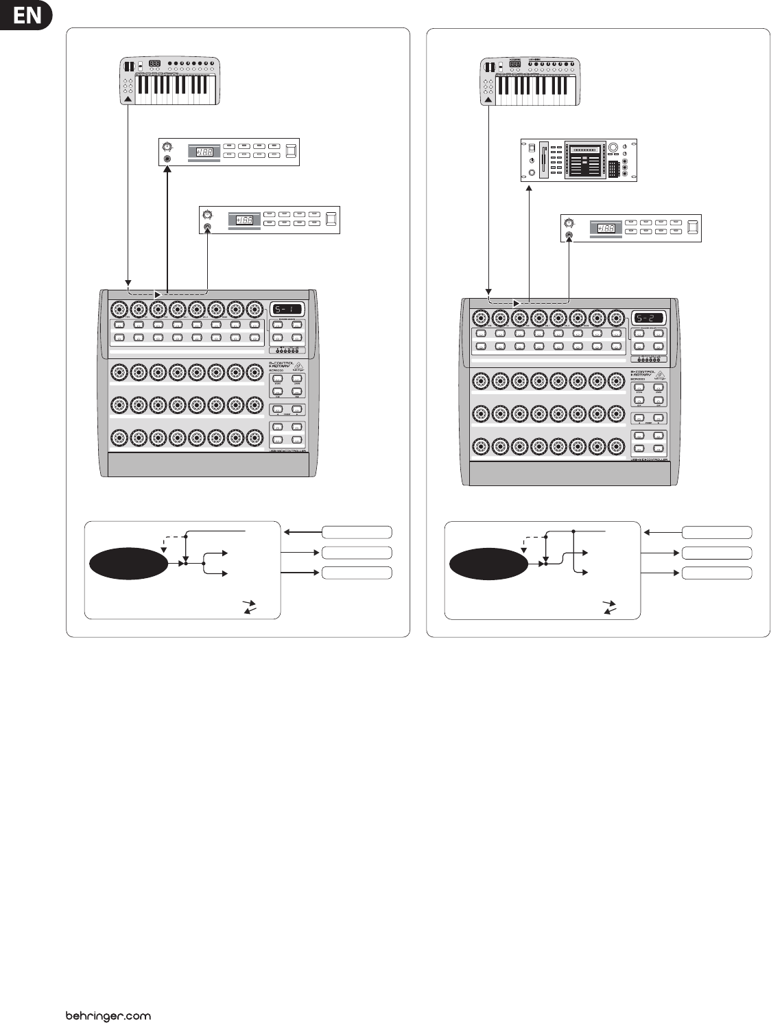
Stand Alone-Mode S-1:
VOLUME MUTE DEMO FILTER LEVEL
PROG TYPE COMBI PLAY POWER
PHONES
MIDI-Expander B
VOLUME MUTE DEMO FILTER LEVEL
PROG TYPE COMBI PLAY POWER
PHONES
MIDI-Expander A
MIDI IN OUT A OUT B/THRU
BCF/BCR2000
Parameter Feedback
Merge
to Computer
from Computer USB
MIDI IN
MIDI OUT A
MIDI OUT B/
THRU
B-CONTROL
MIDI Data Send
MIDI-Expander A
MIDI Keyboard
MIDI-Expander B
MIDI IN
MIDI IN
MIDI OUT
MIDI Keyboard
Fig. 4.6: Routing and use in stand-alone mode 1
S-1 is probably the most frequently used standard operating mode among
the stand-alone applications. We recommend using it when you for example
want to control two sound generators from your B-CONTROL, whereby both
sound generators are played simultaneously from a master keyboard.
To do this, MIDI data from the B-CONTROL and the keyboard have to be
mixed and transmitted on both MIDI OUTs. This is done using the integrated
merge function. The master keyboard is connected to the MIDI input of the
B-CONTROL. Both expanders played from the master keyboard and controlled
by the B-CONTROL are connected at the MIDI outputs. Control data for the
BCF2000 / BCR2000 will probably be program change and real-time controller
commands, while the keyboard will typically transmit keyboard commands
(note on/o, velocity, after touch, pitch bend).
Stand Alone-Mode S-2:
VOLUME MUTE DEMO FILTER LEVEL
PROG TYPE COMBI PLAY POWER
PHONES
MIDI IN
MIDI IN
MIDI IN
MIDI OUT
OUT A OUT B/THRU
MIDI-Expander
Sampler
MIDI Keyboard
BCF/BCR2000
Parameter Feedback
Merge
to Computer
from Computer USB
MIDI IN
MIDI OUT A
MIDI OUT B/
THRU
B-CONTROL
MIDI Data Send
Sampler
MIDI Keyboard
MIDI-Expander B
Fig. 4.7: Routing and use in stand-alone mode 2
Say you want to control just one sound generator from your B-CONTROL because
the tone generator allows extensive editing (e.g. it’s a rack synthesizer or a
sampler, as shown above). The MIDI keyboard should be able to play both sound
generators. In this case, S-2 is the optimal setup. The second sound module can
be a pure preset unit that doesn’t allow any programming. However, it can also
be an eects unit that only receives program commands from the keyboard.
This operating mode is also very useful when the data received by the second unit
is undesired and could otherwise disrupt operation (e.g. to MIDI functions that
cannot be switched o or the MIDI channel can not be changed).
13 B-CONTROL FADER BCF2000/R OTARY BCR2000 User Manual
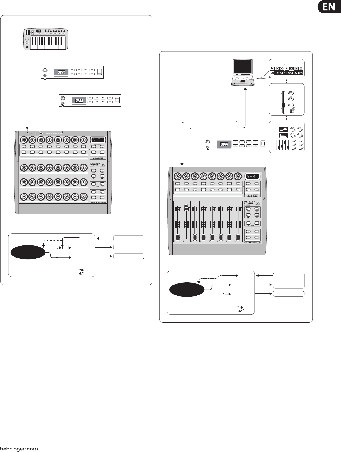
Stand Alone-Mode S-3:
VOLUME MUTE DEMO FILTER LEVEL
PROG TYPE COMBI PLAY POWER
PHONES
MIDI-Expander B
VOLUME MUTE DEMO FILTER LEVEL
PROG TYPE COMBI PLAY POWER
PHONES
MIDI-Expander A
BCF/BCR2000
Parameter Feedback
Merge
to Computer
from Computer USB
MIDI IN
MIDI OUT A
MIDI OUT B/
THRU
B-CONTROL
MIDI Data Send
MIDI-Expander A
MIDI Keyboard
MIDI-Expander B
MIDI IN OUT A OUT B/THRU
MIDI Keyboard
MIDI IN
MIDI IN
MIDI OUT
Fig. 4.8: Routing and use in stand-alone mode 3
In this mode, MIDI data from the BCF2000 / BCR2000 is mixed with the data
coming in at the MIDI input (merge function), but is exported exclusively on
output A. Only control data of the B-CONTROL is available at output B.
This way, you can control two MIDI devices from your B-Control, but only the
device connected at OUT A can additionally be played from the MIDI keyboard.
If you want to daisy-chain two B-CONTROLs to jointly control several MIDI
devices, you need to connect OUT A of the rst B-CONTROL to MIDI IN of the
second B-CONTROL. OUT A of the second B-CONTROL needs to be connected
to the MIDI input of the eects unit. If additional MIDI devices need to be
“talked to,” please connect the THRU port of one MIDI device to the IN port of the
next MIDI device. This way, with dierent MIDI channel assign ments, each MIDI
device can be controlled from each one of the B-CONTROLs.
If additional MIDI inputs are needed, then external MIDI merge boxes must be
used. For example, if your sound module only has one MIDI IN connector, and you
want to control if from several MIDI controllers and from a keyboard, you will
need a 2-in / 1-out merge box.
If additional MIDI outputs are required, you will need external thru boxes.
With more complex MIDI setups, thru boxes are preferred to using longer thru
chains to prevent data transmission problems.
If you don’t require the response function during software control, you can
connect as many BCF2000 / BCR2000s as you want per MIDI. The last B-CONTROL
in the chain is then connected to the MIDI IN input of your computer. This way,
you can control nearly as many channels of a software mixer as you wish.
However, keep in mind that all devices must share 16 MIDI channels.
Stand Alone Mode S-4:
MIDI-Expander
VOLUME MUTE DEMO FILTER LEVEL
PROG TYPE COMBI PLAY POWER
PHONES
MIDI IN
MIDI IN
OUT A
MIDI OUT MIDI IN
OUT B/THRU
Software Sequencer
push
Software Mixer
move/
fade
turn
push
Software Synthesizer
move/
fade
turn
push
BCF/BCR2000
Parameter Feedback
to Computer
from Computer USB
MIDI IN
MIDI OUT A
MIDI OUT B/
THRU
B-CONTROL
MIDI Data Send
Computer
MIDI-Expander
Fig. 4.9: Routing and use in stand-alone mode 4
The Stand Alone mode “S-4” is very similar to mode “S-2”, with the dierence
that the merge function is not available. This mode is ideally suited for
connecting to the MIDI interface of a computer without a USB connector.
The B-CONTROL routes the incoming data to the MIDI output B (the Thru function).
MIDI control commands are laid out at output A. This way, parameter feedback is
possible without the danger of creating a MIDI loop.
Connect the MIDI output on the MIDI interface of your computer to the MIDI
IN input on the B-CONTROL. Connect OUT A to the MIDI input on the interface.
An additional MIDI receiver can be connected to OUT B. An expansion using a
second B-CONTROL is also conceivable. To do that, connect the B output with
MIDI IN on the next MIDI receiver. To send MIDI commands from several units to
your PC, use an external MIDI merge box.

14 B-CONTROL FADER BCF2000/R OTARY BCR2000 User Manual
Important information about stand-alone modes:
With the wiring examples shown here, the parameter values of the controlled
devices can be shown on the B-CONTROL’s LEDs (parameter feedback). If this
is important to you, you will have to connect MIDI IN to the MIDI output of the
device you are controlling. Of course, the hardware unit you are using has to
support sending back the parameter values. If in doubt, check the user manual of
the equipment you are using.
Parameter feedback is enabled in all stand-alone modes. Other stand-alone
modes may cause undesirable MIDI loops. In stand-alone mode 3, the control
data of your B-CONTROL is routed to the MIDI output B without the
merge function.
Your B-CONTROL can also control your computer via MIDI (without a USB
connection) as long as your computer features a MIDI interface. In this case,
all stand-alone modes can be used. To utilize parameter feedback, you should
still use the stand-alone mode 4. Alternatively, you can also use S-3 and connect
the computer via MIDI OUT B so that no MIDI feedback loop is created.
4.2 “Play” mode menu
The Play mode menu is the highest menu level in the B-CONTROL. Use it during
normal operation for real-time control of MIDI data.
Display:
After switching on the unit, the current system software version is briey
displayed. Value changes are shown when using one of the control elements,
provided that they have been activated.
Control elements:
You can use several keys, encoders and faders simultaneously and send their
MIDI data. The classication of MIDI data types is explained in chapter 4.4.
According to its assigned MIDI data type, each control element shows the current
parameter value in the corresponding LED or LED ring.
The position of the faders changes automatically as soon as you choose another
preset or during incoming parameter messages.
LED display:
The encoder LED ring displays or the status LEDs of the buttons change
automatically when running controller recordings in a sequencer, provided,
of course, all connections have been made correctly, the correct operating mode
is enabled and the software sequencer supports sending parameter values.
Button illumination varies according to the controller mode: if a button is in
“Toggle on” mode, the button LED illuminates as soon as the button is pressed.
Only when you press the button once again, the LED goes out. If a button is
in “Toggle o” mode, the corresponding LED will be lit only for the time the
button is pressed.
The performance of the control elements, the display and the LED displays can be
individually set up and is explained in chapter 4.3 “Programming”.
4.2.1 Selecting a preset
• Select a preset with the Preset button (8). The new preset number is
indicated in the display
• Alternatively, you may select a preset by pressing and holding down the
preset button while moving one of the push encoders (1)
• As soon as you release the Preset button, the new preset is active
4.2.2 Copy / Store presets
• Press the STORE button to save a preset. The button LED starts to ash
• Select a memory number using the PRESET buttons or by holding down
one of the PRESET buttons while moving a push encoder at the same time.
The new preset number ashes in the display
• By pressing STORE again, the STORE LED and the display stop ashing
• If you want to overwrite the current preset, press the STORE button twice
(step 2 can be cancelled)
• Cancel the store procedure by pressing the EXIT button
We deliberately did not include an autostore function. That way,
you can assign a new MIDI control to a control element without changing the
currentpreset. If you want to restore a preset, just select another preset briey
and again return to editing. Now, the old data has been restored.
4.2.3 Copying encoder groups
With this function you are able to copy an entire encoder group within a preset.
This saves a lot of programming eort if all encoder groups within a preset
consist of the same basic functions (e.g. MIDI channel, CC number for turn and
push function).
Press the encoder group button of the group you want to copy.
• Press STORE; the STORE button LED ashes
• Now select the destination encoder group. The destination encoder button
LED ashes
• Press STORE again, the STORE button LED is no longer lit
• Cancel the store procedure at any time by pressing EXIT
◊ To permanently store encoder group settings, carry out the preset store
function as explained in chapter 4.2.2.
◊ To copy an encoder group into a different preset, you have to copy an
entire preset! After that, you can copy or rearrange the encoder groups
in the new preset as described above.
4.3 Programming
4.3.1 The LEARN function
The easiest way to assign MIDI functions to individual control elements is to
use the LEARN function. Here, the MIDI data is assigned remotely. For example,
MIDI data sent from a MIDI sequencer to your B-CONTROL is assigned to a control
element selected beforehand.
With LEARN, not only CC, NRPN and note commands can be received but almost
any type of MIDI data, including short SysEx strings.
• Press and hold the LEARN button while operating any control element.
This can be a fader (BCF2000 only), an encoder BCR2000 only),
a PUSH encoder, button, footswitch or sustain pedal (BCF2000 only).
The control element is shown in the display (e.g. E 24 or Fd 8)
◊ When using push encoders, select an encoder group beforehand.
In addition, you have to differentiate between turn and push function.
• Now, release the LEARN button. The B-CONTROL is waiting to receive
MIDI data
• Start transmitting MIDI data from your sequencer. As soon as the data is
received by the BCF2000 / BCR2000, it is shown in the display
• After correct data transmission, the display shows “GOOD” or “BAD” if wrong,
faulty or too extensive data has been sent
• To leave or cancel LEARN, press the EXIT button

15 B-CONTROL FADER BCF2000/R OTARY BCR2000 User Manual
4.3.2 Programming in EDIT mode
Various types of MIDI commands (Pitchbend, After Touch, MMC etc.) are assigned
to the individual control elements in EDIT mode.
• To activate the EDIT mode, press and hold the EDIT button and operate
a control element. This can be a fader, sustain pedal (BCF2000 only),
an encoder (BCR2000 only), a push encoder, a button or footswitch.
The control element is indicated in the display (e.g. E 24 or Fd 8)
◊ When using push encoders, select an encoder group beforehand.
In addition, you have to differentiate between turn and push function.
• Release EDIT; you are now in the EDIT mode
• Using the push encoders, you can now assign MIDI commands to the selected
control element. You will nd all possible MIDI function in tables 4.1 and 4.2,
including all accompanying explanations
• If you want to assign MIDI data to additional control elements, just press
and hold the EDIT button and move one of the control elements. Now, let go
of both controls and use the push encoders to assign a function to it
(see tables 4.1 and 4.2)
• To leave the EDIT mode, press EXIT
◊ Initially, all settings made here are stored temporarily! If you intend to
store them in a preset, please see chapter 4.2.2.
The detailed EDIT functions are described in the following two tables.
With the assignable control elements, we dierentiate between CONTINUOUS
and SWITCH types.
• CONTINUOUS-type control elements (table 4.1) include the eight BCF2000
faders and sustain pedal, the 24 encoders of the BCR2000, the turn function
of the push encoders
• SWITCH-type control elements (table 4.2) are buttons, press functions for
push encoders and footswitches
CONTINUOUS TYPE CONTROLLERS (encoders, turn function of Push Encoders, faders, foot controller)
PUSH ENCODER
12345678
MIDI Data Type MIDI Send Channel Parameter Value 1 Value 2 Controller MODE Controller Option Display Value
PROGRAM CHANGE 1-16 O, Bank Select MSB O, Bank Select LSB — — See below 1* Value indication:
On/O
CC
(Control Change) 1-16 CC-0-127 Min. value:
0-127/16383
Max. value:
0-127/16383
Absolute
Absolute (14-Bit)
Relative 1
Relative 2
Relative 3
Relative 1 (14-Bit)
Relative 2 (14-Bit)
Relative 3 (14-Bit)
See below 1* Value indication:
On/O
NRPN
(Non Registered
Parameter Number)
1-16 NRPN Parameter
Number
Min. value:
0-127/16383
Max. value:
0-127/16383
Absolute
Absolute (14-Bit)
Relative 1
Relative 2
Relative 3
Relative 1 (14-Bit)
Relative 2 (14-Bit)
Relative 3 (14-Bit)
Inc/Dec
See below 1* Value indication:
On/O
PITCH BEND 1-16 —Range 0-127 — — See below 1* Value indication:
On/O
AFTER TOUCH 1-16
Key number
0-127, ALL
(All = Channel
Aftertouch)
Min. value:
0-127
Max. value:
0-127 — See below 1* Value indication:
On/O
GS/XG 1-16
Select GS/XG-Main
Control-parameter
with clear text
indication
Min. value:
0-127"
Max. value:
0-127" — See below 1* Value indication:
On/O
1*) Controller option:
a) Push Encoders LED behaviour: Off, 1d (1 LED on), 1d- (1 LED on, but value 0 = LED off), 2d, 2d-, Bar, Bar-, Spread, Pan, Qual(ity 'Q'), Cut(off), Damp(ing)
b) Faders: Move, Pick-Up, Motor (only BCF2000)
c) Foot controller: Move, Pick-Up (only BCF2000)
Tab. 4.1: Assignment of the push encoders in EDIT mode (CONTINUOUS types)

16 B-CONTROL FADER BCF2000/R OTARY BCR2000 User Manual
SWITCH TYPE CONTROLLERS (buttons, foot switches, push function of Push Encoders)
PUSH ENCODER
12345678
MIDI Data Type MIDI Send Channel Parameter Value 1 Value 2 Controller MODE Controller Option Display Value
PROGRAM CHANGE 1-16 O, Bank Select MSB O, Bank Select LSB
Fixed Program
Change-value:
O, 0 - 127
——Value indication:
On/O
CC
(Control Change) 1-16 CC-0-127 On-value: 0-127 O-Value: O, 0-127
Toggle On
Toggle O
Increment
In case of
'Increment' Steps:
-127...+127
Value indication:
On/O
NRPN
(Non Registered
Parameter Number)
1-16 NRPN Parameter
Number On-value: 0-12 O-Value: O, 0-127
Toggle On
Toggle O
Increment
In case of
'Increment' Steps:
-127...+127
Value indication:
On/O
NOTE (MIDI notes) 1-16 MIDI Note Number:
0-127
Fixed velocity-value:
0-127 —Toggle On
Toggle O —Value indication:
On/O
AFTER TOUCH 1-16
Key number
0-127, ALL
(All = Channel
Aftertouch
Min. value:
0-127
Max. value:
0-127 —
In case of
'Increment' Steps:
-127...+127
Value indication:
On/O
MMC
(MIDI machine
control)
MIDI Device number:
0-126, ALL
Select:
Play, Pause, Stop,
Fwd, Rew
Locate
Punch In
Punch Out
If Frame rate not O Frame Rate:
O
24
25
30
30d
(drop frame)
—Value indication:
On/O
Locate position time
(1st part): hh:mm
Locate position
always sent rst
(before MMC-
command)
Locate positiontime
(2nd part): ss:
(Frames) Locate
position always sent
rst (before MMC-
command)
GS/XG 1-16
Select GS/XG-Main
Control-parameter
with clear text
indication
On-value: 0-127 O-value: O, 0-127 Toggle On
Toggle O —Value indication:
On/O
Tab. 4.2: Assignment of the push encoders in EDIT mode (CONTINUOUS types)
Table explanation:
All settings in the EDIT mode are made by turning the push encoders.
Pressing the push encoder displays its current value. In addition, the setting
options depend on whether the selected control element is a SWITCH type or
CONTINUOUS type.
In the EDIT mode, Push Encoder 1 selects (by turning) the type of command
assigned to a control element.
With Push Encoder 2, select a MIDI channel through which that control
element’s data is sent.
Push Encoders 3 - 5 set parameters and values for the selected MIDI type.
They vary depending on the MIDI function. More details about this subject can be
found later in this chapter.
Push Encoder 6 (Controller Mode) selects how the previously selected control
element behaves, depending on whether it is a SWITCH or a CONTINUOUS type
CONTINUOUS-type elements:
CONTINUOUS-type element controls are divided into “Absolute,” “Absolute
(14 bit),” “Relative 1” (2nd complement), “Relative 2” (binary oset), “Relative 3”
(MSB, most signicant bit), “Relative 1 (14 bit),” “Relative 2 (14 bit),” “Relative 3
(14 bit)” and “Increment/Decrement.” Absolute means absolute data values
although jumps may occur when changing values. With Relative, the current
parameter value is continued independently from the position of the control.
Absolute (14-Bit) or one of the Relative (14-Bit) modes are standard modes
for value changes at NRPNs with high resolution. This is necessary with some
software mixers if more than 128 steps are needed. Increment / Decrement
serves as a step-by-step increase or decrease of values by using the Data
Increment / Decrement commands (see list 5.1 in the appendix).
◊ The classic controler mode for most applications is “absolute”.
All other modes have to be supported by the MIDI software or the
device to be controlled.
Using Push Encoder 7, you can adjust how control elements display information.
Depending on whether you are dealing with an encoder, push encoder, fader or
foot pedal, there are dierent options available:
LED display of the push encoders:
OFF The LED circle remains o.
1d (1 digit): Only one LED lights up (standard setting).
1d- The LED circle operates similar to “1d”, but when the value is 0,
no LED lights up.
2d The display of the LED circles occurs in two stages. If you slowly turn the
encoder from left to right, at rst only one LED lights up, and then the
next LED lights up while the previous LED goes out, and so on. This way,
even the slightest value changes can be accurately represented.
2d- Just like “2d”, but when the value is 0, no LED lights up.
Bar Bar display: when the value is changed, all LEDs light up successively
(for volume etc.).
Bar- Just like bar display, but when the value is 0, no LED lights up.
Sprd Spread: When the value is 0, the upper middle LED lights up; when the
value is increased, the LED circle gradually lights up in both directions
(left and right).
Pan In the middle position (value = 64), only the upper middle LED is on.
With lower values, the LED circle lights up toward the left; with higher
values, the LED circle lights up toward the right (panorama adjustment).

17 B-CONTROL FADER BCF2000/R OTARY BCR2000 User Manual
Qual (Quality Q) has the opposite eect from spread: the LED circle lights
up gradually when you decrease the value. This setting is used for
indicating lter quality with parametric equalizers.
Cut Cuto is optimal for controlling the cuto frequency of a low-pass lter,
for example on a synthesizer. When the value is 0, all LEDs light up.
The LEDs go out successively as you increase the value.
Damp Damping: used for damping lters. When the value is 0, the outer right
LED lights up. If the values are increased, the LED circle fans out from
right to left until all LEDs light up. This way, increasing damping is best
represented when a value goes up.
Encoder LED display (BCR2000):
1d (1 digit): Only one LED lights up at a time (standard setting).
1d- The LED circle operates similar to “1d”, but when the value is 0,
no LED lights up.
Fader functions (BCF2000):
Move If you move the fader by hand, it sends a new value directly. In doing so,
jumps in the parameter value may occur if the current value doesn’t
correspond to the fader position. This can sometimes happen because in
this mode parameter feedback doesn’t cause fader movement.
P-UP Pick up: The fader ignores the parameter feedback. However,
value jumps are avoided because the fader only sends values if the
current value (dierent from the fader setting) is exceeded.
Mot Motor: With parameter feedback, the motorized fader engages
automatically and always indicates the current value.
Foot controller function:
Move The pedal immediately sends value changes. Value jumps may result.
P-UP Pick-Up: The foot pedal become active and sends values only if the set
value is exceeded.
SWITCH-type elements:
Switch-type control elements have three dierent modes: “Toggle On”,
“Toggle O” and “Increment”. Toggle On is similar to a switching function
(e.g. a light switch). Each time you press the switch, the value sent alternates
between the “on” value (set by encoder 4) and the “o” value (set by encoder 5).
This setting is perfect for triggering drum loops from a sampler (press once =
start, press again = stop).
The Toggle O mode corresponds to a momentary-contact button, comparable
to the switch of an electric door opener. The “on” value is sent only as long as
the button is pressed. After releasing the button, the “o” value is sent. Use this
control type to trigger short sound FX or samples (similar to using a keyboard)
by sending Note On and Os.
The Increment option only works for buttons, and only on CC, NRPN and after
touch command types. This mode lets you gradually increase the controller
value with each new keystroke. Set up increment size using encoder 7. If you
repeatedly press a button, the value sent will be increased each time by the
preset amount selected here. If increment size is set to “10,” values 0, 10, 20, 30 ...
110, 120, 0, 10 and so on will be successively sent one after another. You can also
enter negative values (e.g. -10) to achieve a gradual decrease in the value. If you
use encoders 4 and 5 to delineate the lowest and the highest value that are to be
sent, the values always stay within that range here as well. With this function,
you have the option to use your B-CONTROL to control software buttons with
more than two switch positions.
The value display activated using Push Encoder 8 is identical for switch and
continuous elements. If this value display is active, the current value is indicated
in the four-digit display when you actuate a control element. The display shows
the preset number again as soon as you release the control element.
4.4 MIDI messages
Program Change:
With the encoders 3 and 4 you can select bank numbers. If a MIDI device contains
more than 128 presets / programs, rst a bank change command has to be sent.
Even though this is a controller command, it has to be sent before the program
change (and is therefore adjustable) since it is linked to the preset change.
If the bank select message is not needed, simply select “o”.
Encoder 5 selects the program number. If the selected control element is a
control dial (continuous type), the program number is directly selected when
turning the dial. Pressing the switch directly selects the assigned program
number. This can be useful if you always want to start from the same preset.
Control Change CC:
A control change consists of a controller number and its respective value.
Encoder 3 sets the controller number. With buttons, dierent values can be sent
when pressing and releasing (to be set with encoders 4 and 5). This function is
useful if xed parameter settings are to be sent.
With faders and control dials (continuous type), the value range can be
determined by using encoders 4 (minimum value) and 5 (maximum value).
◊ Alternatively, you can invert the value scale by assigning 127 as
the minimum value and 0 as maximum value (scale inversion).
A classic application is the draw bar control of virtual or digital organs
or organ expanders. If assigning controller 7 (volume) to the faders of
the BCF2000 this way, the signal becomes quieter when moving up the
fader. Moving down the fader is similar to moving out the draw bars,
and the volume increases.
NRPN:
A NRPN is needed if none of the 127 standardized controller numbers are
available for a certain function.
Encoder 3 selects the parameter number. For assigning mixer faders,
we recommend the high resolution (“Absolute 14 bit”), provided that the control
hardware / software supports it.
Note:
Of course, a note can only be assigned to one SWITCH element. The note is set
with encoder 3. Note C3 (C key) corresponds with note number 60. Encoder 4 sets
the note velocity (note volume).
Pitch Bend:
Pitch bend is assignable to only one CONTINUOUS element. Since this is a type
of command with its own status byte, selecting a MIDI channel (Encoder 2)
and Range (Encoder 4) is sucient.
After Touch:
Normally, “ALL” is selected here. This means that After Touch aects all notes
equally (“Channel Pressure”). If you want to use a polyphonic After Touch
(“Key Pressure”), the single note on which After Touch should have an eect
can be selected using encoder 3. Since this process is only supported by a few
tone generators, channel After Touch will be best most of the time. When a
switch element has been selected, an “on” and “o” value can also be set
(release dynamic). Therefore, you can limit the modulation range (FX depth)
using After Touch.

18 B-CONTROL FADER BCF2000/R OTARY BCR2000 User Manual
MMC:
MIDI Machine Control data is only assignable to button elements.
Encoder 4 (Value 1) sets “Locate Time” hour and minute values, while encoder 5
(Value 2) sets seconds and frames. The Locate Position is always sent before the
MMC command. We therefore have the following logic-switching sequence:
If the “Locate” parameter has been selected, the sequencer or hard drive recorder
always jumps to the set position. If “Play” has been selected as the parameter
(for a button), the sequencer always starts from the set locator point as soon
as the button is pressed. “Rewind” always begins at the chosen locator point.
Select the frame rate with encoder 6: 24, 25, 30 (non-drop), 30d (drop frame)
or “o” (in this case only the MMC message is sent, without any information of
the locate position).
GS / XG:
Encoder 3 directly selects the most important “Main Control” parameters.
The display indicates them as a (shortened) text (table 4.2). In this case, these are
CCs or NRPNs (no SysEx data).
GS / XG-Parameter Type Display
Filter Cuto NRPN CUTF
Filter Resonance NRPN RESO
Vibrato Rate NRPN RATE
Vibrato Depth NRPN DEPT
Vibrato Delay NRPN DLY
EG Attack NRPN ATC
EG Decay NRPN DCY
EG Release NRPN RELS
Modulation CC 1 MODU
Portamento Time CC 5 PORT
Volume CC 7 VOL
Pan CC 10 PAN
Reverb Send CC 91 REVB
Chorus Send CC 93 CRS
Delay / Variation Send CC 94 VARS
Table 4.3: GS / XG Parameter Main Controls
Encoders 4 and 5 let you conne or invert each controllers’ value range.
4.5 Settings in the global setup menu
Settings that have an eect on all presets are made in the global setup menu.
• Keep the EDIT key pressed and at the same time press the STORE key
• You are now in the global setup menu, and can let go of both keys
• Now, turn the push encoders 1 to 8 to get the desired setting. This is how the
push encoders are allocated
Encoder Function Select
1Operating Mode U-1 ... U-4, S-1 ... S-4
2Global RX Channel O, 1 ... 16
3Footswitch Auto / Normal / Inverted
4Start-Preset 1 ... 32, Last
5Device ID 1 ... 16
6SysEx Dump Single/All
7 — —
8MIDI Data Interval (ms)
Table 4.4: Push encoder allocation in global setup menu
• To exit the global setup menu, press EXIT
• The settings in the global setup menu take eect immediately and do not
have to be separately stored
Operating Mode:
The operating modes are described in chapter 4.1. You can select USB modes
U-1 to U-4 and stand-alone modes S-1 to S-4.
Global RX Channel:
The B-CONTROL receives program change commands on this channel.
Footswitch type:
Because there are dierent kinds of footswitches (depending on their switching
behavior), the polarity of the footswitch connector can be set (normal / inverted),
or it can be automatically detected during power startup (auto recognition).
Start Preset Number:
Each of the 32 presets can be selected as the startup preset. Additionally, with
the “Last” function, at startup you have the option to always load the preset that
was used last.
Device ID Number:
You should change the ID number settings only if you work with several
BCF2000s or BCR2000s at the same time, and problems with recognizing the
correct device start occurring during a SysEx Dump procedure.
◊ Please keep in mind that SysEx Dumps can only be received at the
device number to which they were sent!
SysEx Dump Select:
Turning push encoder 6 lets you select between the current preset (single) or the
entire memory contents of the 32 presets (all) should be sent as a SysEx dump.
One press on encoder 6 triggers the dump.
To receive a SysEx dump, you don’t have to change any settings on your
equipment. If you send a single preset to the B-CONTROL, the data is written to
a temporary memory; to be stored permanently, the data has to be stored on a
storage slot of your choice (preset store function).
◊ WARNING: If you send an “ALL-Dump” to the B-CONTROL, the entire
memory contents are directly overwritten! No request to confirm will
be made, and the memory has no redundant safety function!
• To cancel a SysEx dump, press the EXIT key
MIDI Data Interval:
This is where you adjust the data transmission rate. This setting only has an
eect on MIDI data packs such as SysEx dumps and not on controlling of MIDI
commands (they are carried out in real time anyway). The transmission rate is
adjustable in milliseconds.

19 B-CONTROL FADER BCF2000/ROTARY BCR2000 User Manual
4.6 Additional functions
Temporary “Local O”:
“Local O” means that when you move a control element on the B-CONTROL,
no MIDI data is transmitted. If the position of a control element deviates from
the current value in the software, you can readjust its position until the correct
position is found by using this function. After that, the control can be moved
again without creating an audible value deviation.
Deviations between the position of a control element and the current parameter
value can occur if no parameter feedback is being sent while a value is being
changed in the software (e.g. mixer automation).
• Press the EXIT key and keep it pressed
• Move the desired control element until you get the correct value
• Let go of the EXIT key. The control element can now be moved again
Panic Reset:
This function resets the most important MIDI data to their factory settings.
• Press EDIT and keep it pressed
• Now press EXIT. The reset is performed as soon as you press EXIT.
“PAnC” (for “Panic”) appears in the display
• As soon as the reset is over, your B-CONTROL goes automatically into the play
mode, and the current preset is shown in the display
Data Request:
Current value settings of the MIDI device connected to your B-CONTROL can be
transmitted to your B-CONTROL using the data request function (provided that
the MIDI device supports this function, and a request command was dened
using the editor software). In this case, the MIDI device doesn’t send data;
the B-CONTROL requests them instead.
• Press the LEARN key while the EDIT key is kept pressed. The request takes
place, and the B-CONTROL indicates the controller values of the receiving
MIDI device on the LED ring or through fader positions
Snapshot Send:
A Snapshot Send lets you send all current controller values in order to transmit
the B-CONTROL settings to the connected MIDI device.
• Press the “◄ PRESET” key while the EDIT key is kept pressed. The B-CONTROL
now sends the current controller settings
Single Preset Dump:
In addition to the SysEx Dump function in the global setup menu, the following
key combination lets you send all settings of the current presets:
• Press the “ PRESET ►” key while the EDIT key is kept pressed
• If you want to cancel the dump, press the EXIT key
◊ Snapshot Send and Single Preset Dump differ in the kind of data that
is being sent: With Snapshot Send, only current control values are
transmitted in order to synchronize them with the connected MIDI
device. With Single Preset Dump, the entire contents of the current
preset including the current control assignments are sent. With this
function, you can easily archive certain presets, or swap them with
other B-CONTROL users.
Motor O Function (BCF2000):
The BCF2000 fader motors can be temporarily disengaged. To do that, one or
several fader(s) is / are assigned a key that disengages the fader’s motor for the
duration of the keystroke. All 20 programmable keys ( (2) and (9) ) are available.
• Press the EDIT key and keep it pressed
• Move the fader(s) whose motors you wish to disengage
• Press the key to which you want to assign the motor-o function
• Exit with EXIT
◊ The MIDI command assigned to a key remains preserved. This way,
that MIDI function can be used simultaneously with the fader motor
being disengaged when the key is pressed.

20 B-CONTROL FADER BCF2000/R OTARY BCR2000 User Manual
5. Appendix
Standard MIDI Controller (CC) Numbers
00 Bank Select 32 Bank Select LSB 64 Damper Pedal (Sustain) 96 Data Entry +1 (Increment)
01 Modulation 33 Modulation LSB 65 Portamento On / O 97 Data Entry -1 (Decrement)
02 Breath Controller 34 Breath Controller LSB 66 Sostenuto On / O 98 NRPN LSB
03 Controller 3 (undened) 35 Controller 35 (undened) 67 Soft Pedal On / O 99 NRPN MSB
04 Foot Controller 36 Foot Controller LSB 68 Legato Footswitch 100 RPN LSB
05 Portamento Time 37 Portamento Time LSB 69 Hold 2 101 RPN MSB
06 Data Entry MSB 38 Data Entry LSB 70 Sound Controller 1
(Sound Variation) 102 Controller 102 (undened)
07 Channel Volume
(formerly Main Volume) 39 Channel Volume LSB
(formerly Main Volume) 71 Sound Controller 2
(Resonance / Timbre) 103 Controller 103 (undened)
08 Balance 40 Balance LSB 72 Sound Controller 3 (Release Time) 104 Controller 104 (undened)
09 Controller 9 (undened) 41 Controller 41 (undened) 73 Sound Controller 4 105 Controller 105 (undened)
10 Pan 42 Pan LSB 74 Sound Controller 5 106 Controller 106 (undened)
11 Expression 43 Expression LSB 75 Sound Controller 6 107 Controller 107 (undened)
12 Eect Control 1 44 Eect Control 1 LSB 76 Sound Controller 7 (Vibrato Rate) 108 Controller 108 (undened)
13 Eect Control 2 45 Eect Control 2 LSB 77 Sound Controller 8 (Vibrato Depth) 109 Controller 109 (undened)
14 Controller 14 (undened) 46 Controller 46 (undened) 78 Sound Controller 9 (Vibrato Delay) 110 Controller 110 (undened)
15 Controller 15 (undened) 47 Controller 47 (undened) 79 Sound Controller 10 (undened) 111 Controller 111 (undened)
16 General Purpose 1 48 General Purpose 1 LSB 80 General Purpose 5 112 Controller 112 (undened)
17 General Purpose 2 49 General Purpose 2 LSB 81 General Purpose 6 113 Controller 113 (undened)
18 General Purpose 3 50 General Purpose 3 LSB 82 General Purpose 7 114 Controller 114 (undened)
19 General Purpose 4 51 General Purpose 4 LSB 83 General Purpose 8 115 Controller 115 (undened)
20 Controller 20 (undened) 52 Controller 52 (undened) 84 Portamento Control 116 Controller 116 (undened)
21 Controller 21 (undened) 53 Controller 53 (undened) 85 Controller 85 (undened) 117 Controller 117 (undened)
22 Controller 22 (undened) 54 Controller 54 (undened) 86 Controller 86 (undened) 118 Controller 118 (undened)
23 Controller 23 (undened) 55 Controller 55 (undened) 87 Controller 87 (undened) 119 Controller 119 (undened)
24 Controller 24 (undened) 56 Controller 56 (undened) 88 Controller 88 (undened) 120 All Sound O
25 Controller 25 (undened) 57 Controller 57 (undened) 89 Controller 89 (undened) 121 Reset All Controllers
26 Controller 26 (undened) 58 Controller 58 (undened) 90 Controller 90 (undened) 122 Local Control On/O
27 Controller 27 (undened) 59 Controller 59 (undened) 91 Eects 1 Depth (Reverb) 123 All Notes O
28 Controller 28 (undened) 60 Controller 60 (undened) 92 Eects 2 Depth (Tremolo) 124 Omni Mode O
29 Controller 29 (undened) 61 Controller 61 (undened) 93 Eects 3 Depth (Chorus) 125 Omni Mode On
30 Controller 30 (undened) 62 Controller 62 (undened) 94 Eects 4 Depth 126 Poly Mode O / Mono Mode On
31 Controller 31 (undened) 63 Controller 63 (undened) 95 Eects 5 Depth (Phaser) 127 Poly Mode On / Mono Mode O
Table 5.1: Standard MIDI Controller
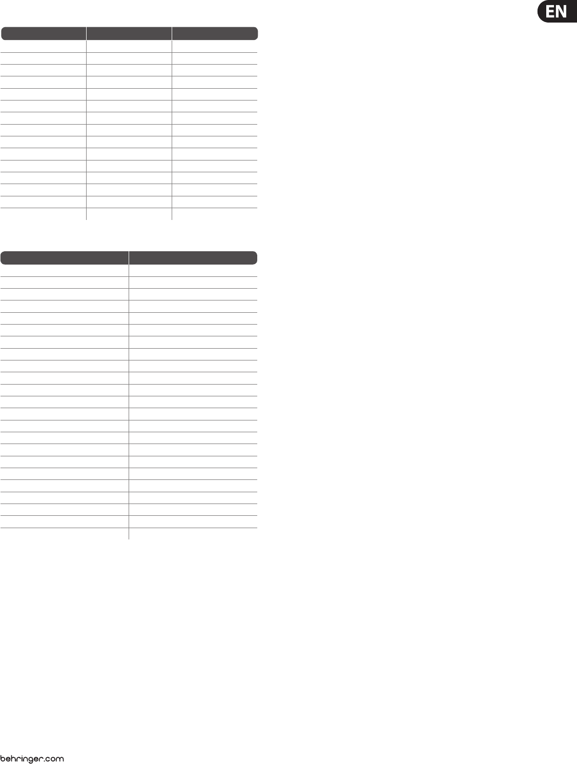
21 B-CONTROL FADER BCF2000/R OTARY BCR2000 User Manual
GS / XG-Parameter Type Display
Filter Cuto NRPN CUTF
Filter Resonance NRPN RESO
Vibrato Rate NRPN RATE
Vibrato Depth NRPN DEPT
Vibrato Delay NRPN DELY
EG Attack NRPN ATTA
EG Decay NRPN DECY
EG Release NRPN RELS
Modulation CC 1 MODU
Portamento Time CC 5 PORT
Volume CC 7 VOL
Pan CC 10 PAN
Reverb Send CC 91 REVB
Chorus Send CC 93 CHOR
Delay/Variation Send CC 94 VARI
Table 5.2: GS / XG Parameter Main Controls
Musical Note MIDI Note Number
C-2 0
C#-2 / Db-2 1
D-2 2
D#-2 / Eb-2 3
E-2 4
F-2 5
F#-2 / Gb-2 6
G-2 7
G#-2 / Ab-2 8
A-2 9
A#-2 / Bb-2 10
B-2 11
C-1 12
C0 24
C1 36
C2 48
C3 (Clef C) 60 (Yamaha-Convention)
C4 72
C5 84
C6 96
C7 108
C8 120
G8 127
Table 5.3: MIDI note number assignment
22 B-CONTROL FADER BCF2000/R OTARY BCR2000 User Manual
6. Specications
USB Interface
Type Full-speed 12 MBit/sec. USB MIDI
class-compliant
MIDI Interface
Type 5-pin DIN connectors IN, OUT A, OUT B / THRU
Control Elements
BCF2000
Controls 8 motorized 100-mm faders
8 innitely variable push encoders with
LED rings
Keys 20 keys 10 system keys (4x Encoder Group,
4x programming, 2x Preset)
BCR2000
Controls 4 innitely variable encoders with LED rings
8 innitely variable push encoders with
LED rings
Keys 20 keys 10 system keys (4x Encoder Group,
4x programming, 2x Preset)
Display
Type 4-digit 7-segment LED display
Switched Inputs
BCF2000
Footswitch 1 x ¼" TS connector with automatic
polarity detection
Foot pedal 1 x ¼" TRS connector
BCR2000
Footswitch
Input 1 ¼" TRS stereo connector for dual-footswitch
Input 2 ¼" TS connector both with automatic
polarity detection
Power Supply
Voltage 100 to 240 V~, 50/60 Hz
Power Consumption max. 10 W
Fuse T 1 A H 250 V
Mains Connection Standard IEC receptacle
Dimensions / Weight
BCF2000
Dimensions (H x W x D) approx. 13 x 4 x 11 /" / 330 x 100 x 300 mm
Weight approx. 5.9 lbs / 2.7 kg
BCR2000
Dimensions (H x W x D) approx. 13 x 4 x 11 /" / 330 x 100 x 300 mm
Weight approx. 5.1 lbs / 2.3 kg
BEHRINGER is constantly striving to maintain the highest professional standards. As a result of these efforts,
modifications may be made from time to time to existing products without prior notice. Specifications and
appearance may differ from those listed or illustrated.

23 B-CONTROL FADER BCF2000/R OTARY BCR2000 User Manual
FEDERAL COMMUNICATIONS
COMMISSION COMPLIANCE
INFORMATION
Responsible Party Name: MUSIC Group Services US Inc.
Address: 18912 North Creek Parkway,
Suite 200 Bothell, WA 98011,
USA
Phone/Fax No.: Phone: +1 425 672 0816
Fax: +1 425 673 7647
B-CONTROL FADER BCF2000/
B-CONTROL ROTARY BCR2000
complies with the FCC rules as mentioned in the followingparagraph:
This equipment has been tested and found to comply with the limits for a ClassB
digital device, pursuant to part 15 of the FCC Rules. These limits are designed
to provide reasonable protection against harmful interference in a residential
installation. This equipment generates, uses and can radiate radio frequency
energy and, if not installed and used in accordance with the instructions, may cause
harmful interference to radio communications. However, there is no guarantee that
interference will not occur in a particular installation. If this equipment does cause
harmful interference to radio or television reception, which can be determined
by turning the equipment o and on, the user is encouraged to try to correct the
interference by one or more of the followingmeasures:
• Reorient or relocate the receiving antenna.
• Increase the separation between the equipment and receiver.
• Connect the equipment into an outlet on a circuit dierent from that to which the
receiver is connected.
• Consult the dealer or an experienced radio/TV technician forhelp.
This device complies with Part 15 of the FCC rules. Operation is subject to the
following two conditions:
(1) this device may not cause harmful interference, and
(2) this device must accept any interference received, including interference that may
cause undesired operation.
Important information:
Changes or modications to the equipment not expressly approved by MUSIC Group
can void the user’s authority to use the equipment.
B-CONTROL FADER BCF2000/
B-CONTROL ROTARY BCR2000

We Hear You
