Behringer Europower Pmp1680S Users Manual PMP1680S/PMP980S/PMP960M
Behringer-Europower-Pmp980S-Owners-Manual behringer-europower-pmp980s-owners-manual
Behringer-Europower-Pmp1680S-Owners-Manual behringer-europower-pmp1680s-owners-manual
Behringer-Europower-Pmp960M-Owners-Manual behringer-europower-pmp960m-owners-manual
2015-06-29
: Behringer Behringer-Europower-Pmp1680S-Users-Manual-752255 behringer-europower-pmp1680s-users-manual-752255 behringer pdf
Open the PDF directly: View PDF ![]() .
.
Page Count: 15

User Manual
EUROPOWER
PMP1680S/PMP980S/PMP960M
1600/900-Watt 10/6-Channel Powered Mixer with
Dual Multi-FX Processor and FBQ Feedback Detection System

2EUROPOWER PMP1680S/PMP980S/PMP960M User Manual
Thank you
Thank you for choosing one of the PMP series powered mixers from BEHRINGER.
These mixers pack impressive features such as digital eects, graphic EQs,
FBQfeedback destroyer and unique voice cancelling function – all in a
lightweight, portable package. You now have a versatile combination of inputs,
routing options, eects and power amp operations for your rehearsal space,
smallvenue or portable PA needs. But why bother with manuals? We know
you want to get started right away, but please read this manual carefully and
keep it handy for ongoing reference. These instructions show you all the inside
features, tricks, and tips you need to build the best possible sound with your new
PMPpowered mixer.
After all, it’s all about your sound.
Table of Contents
Thank you .......................................................................2
Important Safety Instructions ...................................... 3
Legal Disclaimer ............................................................. 3
Limited warranty ............................................................ 3
1. Before you get Started .............................................. 4
1.1 Shipment ................................................................................ 4
1.2 Initial operation ................................................................... 4
1.3 Online registration ............................................................. 4
1.4 The manual ........................................................................... 4
2. Control Elements ....................................................... 6
2.1 Mono and stereo channels .............................................. 6
2.2 Eects section ..................................................................... 6
2.3 Main and monitor section ............................................... 6
2.4 Rear panel ............................................................................. 7
3. Digital Eects Processor ........................................... 8
4. Installation ................................................................. 8
4.1 Mains connection ............................................................... 8
4.2 Audio connections ............................................................. 8
4.3 Loudspeaker connection ................................................. 9
5. Wiring Examples ...................................................... 10
6. Specications ........................................................... 12

3EUROPOWER PMP1680S/PMP980S/PMP960M User Manual
Important Safety
Instructions
LEGAL DISCLAIMER
LIMITED WARRANTY
Terminals marked with this symbol carry
electrical current of su cient magnitude
to constitute risk of electric shock.
Use only high-quality professional speaker cables with
¼" TS or twist-locking plugs pre-installed. Allother
installation or modi cation should be performed only
by quali edpersonnel.
This symbol, wherever it appears,
alertsyou to the presence of uninsulated
dangerous voltage inside the
enclosure-voltage that may be su cient to constitute a
risk ofshock.
This symbol, wherever it appears,
alertsyou to important operating and
maintenance instructions in the
accompanying literature. Please read the manual.
Caution
To reduce the risk of electric shock, donot
remove the top cover (or the rear section).
No user serviceable parts inside. Refer servicing to
quali ed personnel.
Caution
To reduce the risk of re or electric shock,
do not expose this appliance to rain and
moisture. The apparatus shall not be exposed to dripping
or splashing liquids and no objects lled with liquids,
suchas vases, shall be placed on the apparatus.
Caution
These service instructions are for use
by quali ed service personnel only.
Toreduce the risk of electric shock do not perform any
servicing other than that contained in the operation
instructions. Repairs have to be performed by quali ed
servicepersonnel.
1. Read these instructions.
2. Keep these instructions.
3. Heed all warnings.
4. Follow all instructions.
5. Do not use this apparatus near water.
6. Clean only with dry cloth.
7. Do not block any ventilation openings. Install in
accordance with the manufacturer’s instructions.
8. Do not install near any heat sources such as
radiators, heat registers, stoves, or other apparatus
(including ampli ers) that produce heat.
9. Do not defeat the safety purpose of the polarized
or grounding-type plug. A polarized plug has two blades
with one wider than the other. A grounding-type plug
has two blades and a third grounding prong. The wide
blade or the third prong are provided for your safety. Ifthe
provided plug does not t into your outlet, consult an
electrician for replacement of the obsolete outlet.
10. Protect the power cord from being walked on or
pinched particularly at plugs, convenience receptacles,
and the point where they exit from the apparatus.
11. Use only attachments/accessories speci ed by
themanufacturer.
12. Use only with the
cart, stand, tripod, bracket,
or table speci ed by the
manufacturer, orsold with
the apparatus. When a cart
is used, use caution when
moving the cart/apparatus
combination to avoid
injury from tip-over.
13. Unplug this apparatus during lightning storms or
when unused for long periods of time.
14. Refer all servicing to quali ed service personnel.
Servicing is required when the apparatus has been
damaged in any way, such as power supply cord or plug
is damaged, liquid has been spilled or objects have fallen
into the apparatus, the apparatus has been exposed
to rain or moisture, does not operate normally, or has
beendropped.
15. The apparatus shall be connected to a MAINS socket
outlet with a protective earthing connection.
16. Where the MAINS plug or an appliance coupler is
used as the disconnect device, the disconnect device shall
remain readily operable.
TECHNICAL SPECIFICATIONS AND APPEARANCES
ARE SUBJECT TO CHANGE WITHOUT NOTICE AND
ACCURACY IS NOT GUARANTEED. BEHRINGER,
KLARKTEKNIK, MIDAS, BUGERA, AND TURBOSOUND
ARE PART OF THE MUSIC GROUP MUSICGROUP.COM.
ALL TRADEMARKS ARE THE PROPERTY OF THEIR
RESPECTIVE OWNERS. MUSICGROUP ACCEPTS NO
LIABILITY FOR ANY LOSS WHICH MAY BE SUFFERED
BY ANY PERSON WHO RELIES EITHER WHOLLY OR
IN PART UPON ANY DESCRIPTION, PHOTOGRAPH
OR STATEMENT CONTAINED HEREIN. COLORS AND
SPECIFICATIONS MAY VARY FROM ACTUAL PRODUCT.
MUSIC GROUP PRODUCTS ARE SOLD THROUGH
AUTHORIZED FULLFILLERS AND RESELLERS ONLY.
FULLFILLERSAND RESELLERS ARE NOT AGENTS OF
MUSICGROUP AND HAVE ABSOLUTELY NO AUTHORITY
TO BIND MUSICGROUP BY ANY EXPRESS OR IMPLIED
UNDERTAKING OR REPRESENTATION. THIS MANUAL
IS COPYRIGHTED. NO PART OF THIS MANUAL MAY
BE REPRODUCED OR TRANSMITTED IN ANY FORM
OR BY ANY MEANS, ELECTRONIC OR MECHANICAL,
INCLUDING PHOTOCOPYING AND RECORDING OF ANY
KIND, FOR ANY PURPOSE, WITHOUT THE EXPRESS
WRITTEN PERMISSION OF MUSICGROUPIPLTD.
ALL RIGHTS RESERVED.
© 2013 MUSICGroupIPLtd.
Trident Chambers, Wickhams Cay, P.O. Box 146,
Road Town, Tortola, British Virgin Islands
For the applicable warranty terms and conditions
and additional information regarding MUSIC Group’s
Limited Warranty, please see complete details online at
www.music-group.com/warranty.

4EUROPOWER PMP1680S/PMP980S/PMP960M User Manual
1. Before you get Started
1.1 Shipment
Your PMP mixer was carefully packed at the factory and the packaging is
designed to protect the unit from rough handling. Nevertheless, we recommend
that you carefully examine the packaging and its contents for any signs of
physical damage which may have occurred during transit.
◊ If the unit is damaged, please do NOT return it to BEHRINGER,
but notify your dealer and the shipping company immediately.
Otherwise, claims for damage or replacement may not be granted.
◊ We recommend that you use a flight case, so as to give your power
mixer optimum protection during use or transport.
◊ Always use the original packing carton to prevent damage during
storage or transport.
◊ Make sure that children cannot play unsupervised with the device or
its packaging.
◊ Please ensure proper disposal of all packing materials.
1.2 Initial operation
Be sure that there is enough air space around the unit for cooling and, to avoid
overheating, please do not place the EUROPOWER near radiators, etc.
◊ Blown fuses must be replaced by fuses of the same type and rating!
Please refer to the “Specifications” for details.
The mains connection is made using the enclosed power cord and a standard IEC
receptacle. It meets all of the international safety certication requirements.
◊ Please make sure that all units have proper ground connection.
For your own safety, never remove or disable the ground conductor
from the unit or on the AC power cord.
◊ Important notes concerning installation: The sound quality may
diminish within the range of powerful broadcasting stations and
high-frequency sources. Increase the distance between the transmitter
and the device and use shielded cables for all connections.
1.3 Online registration
Please register your new BEHRINGER equipment right after your purchase
by visiting http://behringer.com and read the terms and conditions of our
warrantycarefully.
Should your BEHRINGER product malfunction, it is our intention to have it
repaired as quickly as possible. To arrange for warranty service, please contact
the BEHRINGER retailer from whom the equipment was purchased. Shouldyour
BEHRINGER dealer not be located in your vicinity, you may directly contact
one of our subsidiaries. Corresponding contact information is included in the
original equipment packaging (Global Contact Information/European Contact
Information). Should your country not be listed, please contact the distributor
nearest you. A list of distributors can be found in the support area of our website
(http://behringer.com).
Registering your purchase and equipment with us helps us process your repair
claims more quickly and eciently.
Thank you for your cooperation!
1.4 The manual
This manual is designed to give you both an overview of all control elements and
to provide detail about how to use them. To provide you with a clear structure,
we have grouped the control elements according to their function. They can
easily be found on the enclosed numbered illustrations. If you need more
detailed information on specic topics, please visit our web site behringer.com.
The product-related information pages and the Ultranet-based glossary explain
the relevant audio engineering terminology in full detail.
5EUROPOWER PMP1680S/PMP980S/PMP960M User Manual
(34)
(32)
(36)
(1)
(2)
(3)
(4)
(5)
(6)
(8)
(14)
(16) (21) (20) (19) (24)
(23)
(28)
(29)
(30)
(26)(25)(22)(20)(21)
(15)
(18)
(17)
(27)
(31)
(13)
(12)
(10)
(11)
(9)
(12)
(40)
(33) (35) (37) (39)(38)
(1)
(2)
(3)
(4)
(5)
(7)
(8)
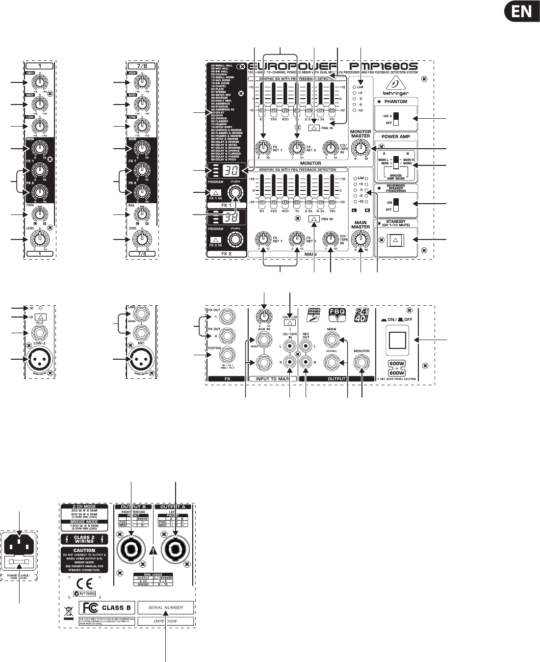
Front Panel
Rear Panel
(41)
(42)
(44) (43)
(45)

6EUROPOWER PMP1680S/PMP980S/PMP960M User Manual
2. Control Elements
A detailed description of all functions of your power mixer can be found in the
following chapters. Please also refer to the enclosed sheet with the numbered
illustrations to get an overview of the control layout.
2.1 Mono and stereo channels
(1) The HIGH control in the EQ section governs the high-frequency range of the
respective channel.
(2) Use the MID control to boost or cut the mid-range frequencies.
(3) The LOW control allows you too boost/cut the low-frequency range.
(4) With the MON control you can adjust the volume of each channel in the
monitor mix.
(5) The FX control determines the signal level sent from each channel to the
built-in eects processor; this signal is also present at the FX OUT jack
(see (32) ). The PMP980S/PMP1680S has two FX controls (FX 1 and FX 2),
sothat you can use two eects simulteneously. Accordingly, it also provides
two eect Aux paths (see (32) ).
◊ Please note that the effects processor signal will be inaudible when the
FX RETURN control (21) is set fully counter-clockwise.
(6) For the mono input channels, the PMP980S/PMP1680S has a PAN(ORAMA)
control which determines the position of the channel signal in the stereo
main mix. The PMP960M has no PAN on the input channels, because it is a
dual-mono power mixer.
(7) The BAL(ANCE) control for the stereo channels of the PMP980S/PMP1680S
corresonds to the PAN control for the mono channels. It determines the
relative volume of the left and right input signals before they are routed to
the stereo main output. The PMP960M has no stereo channels and hence no
BAL control, because it is a dual-mono power mixer.
(8) The LEVEL control adjusts the channel signal level in the main mix.
2.1.1 Input section
(9) The CLIP LED is very useful to control the input gain. It should never be
constantly illuminated (only with signal peaks).
(10) The PAD switch reduces the input sensitivity of the channel by
approx.30dB,to connect for example line-level signals.
(11) The balanced HI-Z input (¼" TRS) can be used for line-level signal sources,
e.g. keyboards, electric guitars and basses.
(12) Each channel has a balanced LOW-Z microphone input with XLR connectors,
which also supply the +48 V phantom power for condenser microphones
(see (27) ).
(13) Unbalanced stereo line inputs with ¼" connectors for stereo channels 7 to 10
of the PMP980S/PMP1680S. They can be used for connecting keyboards with
stereo outputs or stereo drum machines.
◊ Please remember to use either the microphone or the line input of a
channel at a time, but never both at the same time!
2.2 Eects section
(14) List of all multi-eects presets.
(15) LED level meter of the eects processor. Since the PMP980S/PMP1680S
allows you to select two eects simultaneously, it also has two level meters
(DUAL FX). Be sure that the clip LED illuminates for signal peaks only. If it is
illuminated all the time, it is a sign that the eects processor is overloading
and hence producing unpleasant distortion.
(16) The Eect display (PMP980S/PMP1680S: two displays) shows the currently
selected preset.
(17) Turn the PROGRAM control (PMP980S/PMP1680S: one control each for
FX1and FX 2) to select an eects preset (preset number starts ashing).
Push the control briey to conrm your selection.
(18) Press the FX IN button (PMP980S/PMP1680S: FX 1 IN and FX 2 IN) to activate
the eects processor.
2.3 Main and monitor section
(19) Your power mixer is equipped with two graphic 7-band equalizers. Theupper
one processes the monitor signal, the lower one the main signal. Use the EQs
to adjust the sound to the room acoustics.
(20) Press the FBQ IN switch to activate the FBQ Feedback Detection System.
The frequencies causing feedback are shown by the brightly lit fader LEDs.
Simply lower the level of the respective frequency range until feedback
disappears and the LED goes out. Your power mixer oers this function both
for the main and the monitor mix.
(21) Turn the FX RET control to add the eect signal to the main mix (lower)
ormonitor mix (upper). The PMP980S/PMP1680S allows you to use two
eects at the same time, it also has two FX controls each for the main
and monitor mixes: when the FX RET 1 and FX RET 2 controls are fully
counterclockwise, no eect signal is added.
(22) The CD/TAPE IN control adjusts the volume of the 2 Track In signal (see (35) ).
(23) The MONITOR MASTER control adjusts the monitor output volume.
(24) Use this 5-digit LED meter to control the output level of the monitor signal.
The upper LIM LED illuminates when the internal amp protection circuit
responds to output levels that are too high.
(25) The MAIN MASTER control is used to adjust the main output volume.
(26) Use this 5-digit LED meter to control the output level of the main signal.
ThePMP980S/PMP1680S has two rows of LED meters (L/R), because the
signal is stereo. The upper LIM LED illuminates when the internal amp
protection circuit responds to output levels that are too high.
(27) +48 V phantom power is provided for condenser microphones. The phantom
power supply is activated for all channels with the PHANTOM switch and the
PHANTOM LED above the switch illuminates.
(28) Use the POWER AMP switch to determine the operating mode of your
powermixer.
The PMP980S/PMP1680S has three dierent operating modes:
InMAINL/MAIN R mode it functions as a stereo amplier, i.e. the left
and right main stereo signals are sent to OUTPUT A (L) and OUTPUT B (R).
InMON/MONO mode it functions as a dual mono amplier, i. e. OUTPUT A
sends the monitor signal, and OUTPUT B the main signal (mono). In BRIDGE
AMP MODE the output power of outputs A and B are added and provided
atOUTPUT B.
The PMP960M also has three operating modes, since it can be
operated in two modes with the switch in its upper position
(MAIN/MAIN(BRIDGE)mode), depending on the pin connections of the
speaker cables. In MAIN/MAIN (BRIDGE) mode power of both outputs is
added and provided at OUTPUT B (Locking cable, pins 1+/2+). Withthe
normal pin connections (Locking cable, pins 1+/1-) a main signal is provided
in this mode at OUTPUT A and B (not bridged). In MON/MAIN mode,
themixer can also be used as a dual mono amplier, i.e. OUTPUT A provides
the monitor signal, while the main signal is present at OUTPUT B.
Please refer to (44) and (45) as well as chapter 4.4 “Loudspeaker connectors”.

7EUROPOWER PMP1680S/PMP980S/PMP960M User Manual
◊ In BRIDGE mode, always connect only one loudspeaker with
an impedance of at least 8 Ω to OUTPUT B (pins 1+/2+)!
Please note that OUTPUT A must NEVER be used in BRIDGE mode
(with pin connections 1+/2+)!
◊ In all other operating modes, the minimum impedance of the speaker
connected must not fall below 4 Ω.
(29) Use the SPEAKER PROCESSING switch to activate a lter that adapts
the mixer to the specications of your loudspeakers. If the speakers have
a limited frequency response in the bass range, it allows you to adapt it
optimally to the frequency response of the speakers.
(30) If STANDBY is pressed, all input channels are muted. During breaks you
can thus prevent the microphones from picking up noise or interference,
which would then be reproduced by the P.A. system. The advantage is that
all faders can be left untouched while you play a CD via the CD/TAPE inputs
(see(35) ). There is also no need to move down the faders of muted channels
and lose your mix.
2.3.1 Connectors
(31) The FOOTSWITCH connector is for a standard footswitch. You can activate
an “eect bypass” that mutes the eects processor. Please use a dual
footswitch for the PMP980S/PMP1680S, so that you can enable/disable FX1
and FX 2 independently of each other. In this case, the tip of the ¼" plug
controls FX 1, and the ring FX 2.
(32) The FX OUT connector is used to route the FX SEND signal from the input
channels, for example, to the input of an external eects processor.
ThePMP980S/PMP1680S has two FX controls per input signal (see (5) )
andalso two FX OUT connectors (FX OUT 1 and FX OUT 2).
◊ Please note: When you connect a mono plug to one of the FX OUT jacks,
the signal path from the respective FX send to the built-in effects
processor is interrupted. For each FX send you can either use the
built-in effect or the corresponding FX OUT jack (for an external effect),
but never both at the same time. When you use a stereo plug (tip and
ring interconnected) you can use the built-in effects processor and the
FX OUT jacks in parallel.
(33) Use the AUX IN ¼" inputs to route an external stereo signal to the main mix.
This can be the signal generated by an external eects processor. Use the
left input for mono signals, which are then reproduced on both stereo sides.
ThePMP960M has only one mono AUX IN connector.
(34)
The AUX IN control adjusts the volume of the external signal in the main mix.
(35) The CD/TAPE IN RCA input allows you to feed in external stereo signals,
e.g.from a CD player, tape deck or other line-level source.
(36) The VOICE CANCELLER lters vocal-specic frequencies from the CD/TAPE IN
signal. This function can be used for karaoke, i.e. you can remove the vocals
from a song and then sing along with the music yourself.
(37) The REC OUT (RCA) provides line-level signals from the power mixer to a
DAT recorder, for example. On the PMP980S/PMP1680S the REC OUT signal is
stereo and on the PMP960M two identical mono signals are provided.
◊ If the REC OUT signal is connected to a recorder whose output signal
is returned to the CD/TAPE IN, feedback can occur when you activate
the record function. So, disconnect the CD/TAPE IN from the recorder,
before you start recording!
(38) The MAIN ¼" connectors allow you to send the main signal to an external
amplier, when you only wish to use the mixer and eects section.
Thesignal is taken pre-power stage of the mixer. It is also possible to
use only the left jack of the output. The PMP960M has only one mono
outputconnector.
(39) Connect your monitor power amps or active monitor speakers to the mono
MONITOR output to monitor the signal mix created with the MON controls
or to route it to the musicians on stage.
(40) Use the POWER switch to put the unit into operation. The POWER switch
should always be in the “O” position when you are about to connect the
unit to the mains.
◊ Please note: The POWER switch does not fully disconnect the unit from
the mains. Unplug the power cord completely when the unit is not used
for prolonged periods of time.
2.4 Rear panel
(41) The mains connection is on a standard IEC receptacle. An appropriate power
cord is supplied with the unit.
(42) FUSE HOLDER. Before connecting the unit to the mains, ensure that
the voltage setting matches your local voltage. Blown fuses should only
be replaced by fuses of the same type and rating. Please also read the
information given in chapter 6 “Specications”.
(43) Loudspeaker OUTPUT A.
PMP980S/PMP1680S: Depending on the operating mode selected (see (28) )
either the left main signal or the monitor signal is provided at OUTPUT A.
Never use this output in bridged mono mode.
PMP960M: In MON/MAIN mode, the monitor signal is provided at
OUTPUTA (see (28) ). Never use this output in bridged mono mode,
exceptwhen you use a cable with the normal pin connections (pins1+/1-).
In this case you can take the mono main signal from this output in
MAIN/MAIN (BRIDGE) mode (not bridged). Please also refer to chapter 4.3
“Loudspeakerconnection”.
◊ The impedance of the loudspeaker connected must not fall below 4 Ω.
◊ Please note that the power delivered to the speaker in bridged
mono mode is considerably higher than in other operating modes.
Please read the information given on the rear panel of the power mixer.
(44) Loudspeaker OUTPUT B.
PMP980S/PMP1680S: Depending on the operating mode selected (see (28) )
either the right main signal, the mono main signal or the bridged mono
signal is provided at OUTPUT B.
PMP960M: Either the main or the bridged main mono signal is provided at
OUTPUT B (see (28) ). When you use a cable with the normal pin connections
(pins 1+/1-), it is possible in MAIN/MAIN (BRIDGE) mode to take the mono
main signal from this output (not bridged). Please also refer to chapter 4.3
“Loudspeaker connection”.
◊ In BRIDGE mode, always connect only one loudspeaker with an
impedance of at least 8 Ω to OUTPUT B (pins 1+/2+)! Please note
that OUTPUT A must NEVER be used in BRIDGE mode (with pin
connections 1+/2+)!
◊ In all other operating modes, the minimum impedance of the speaker
connected must not fall below 4 Ω.
◊ Information on how to properly connect your speaker with regard to
polarity can be found on the rear of the mixer (PINOUTs).
(45) SERIAL NUMBER.
8EUROPOWER PMP1680S/PMP980S/PMP960M User Manual
3. Digital Eects Processor
24-BIT MULTI-EFFECTS PROCESSOR
This built-in eects module produces high-grade standard eects such as
reverb, chorus, anger, delay and various combination eects. The integrated
eects module has the advantage of requiring no wiring. This way, the danger
of creating ground loops or uneven signal levels is eliminated at the outset,
completely simplifying the handling.
These eect presets are designed to be added to dry signals. If you move the
FXRET control, you mix the channel signal (dry) and the eect signal.
◊ Turn down the FX controls in those channel strips whose signals you
don’t wish to process.
4. Installation
4.1 Mains connection
Blown fuses must be replaced by fuses of the same type and rating.
The mains connection is made using the enclosed power cord and a standard IEC
receptacle. It meets all of the international safety certication requirements.
◊ Please make sure that all units have a proper ground connection.
For your own safety, never remove or disable the ground conductor
from the unit or of the AC power cord.
4.2 Audio connections
The inputs and outputs of the BEHRINGER EUROPOWER are unbalanced ¼" TS
connectors—except for the balanced mono line inputs. Of course, all inputs and
outputs work with both balanced and unbalanced connectors. The Tape Ins and
Outs are on stereo RCA connectors.
◊ Please ensure that only qualified personnel install and operate the
power mixer. During installation and operation, the user must have
sufficient electrical contact to earth. Electrostatic charges might affect
the operation of the unit.
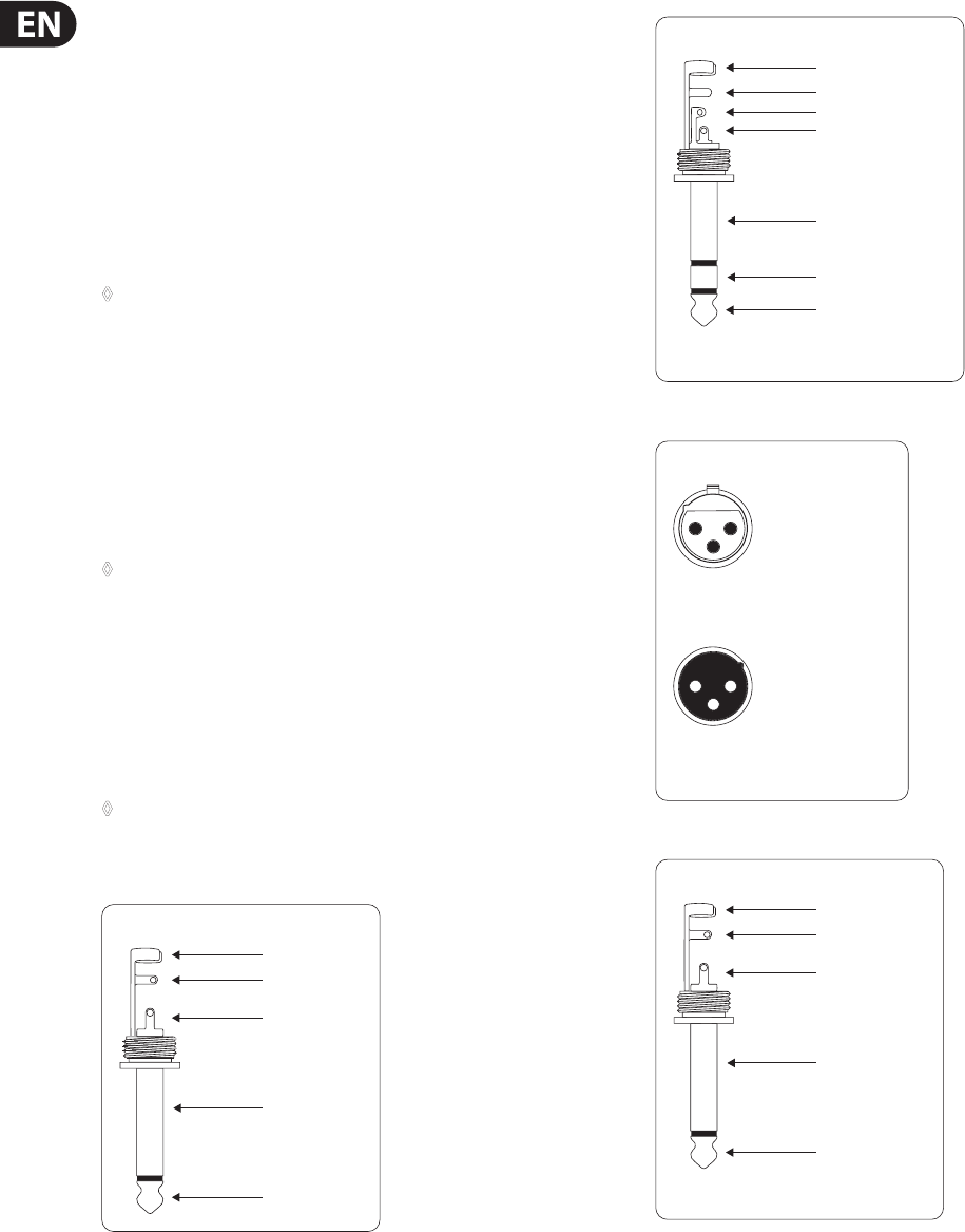
Fig. 4.1: ¼" TS connector
strain relief clamp
sleeve
tip
sleeve
(ground/shield)
Unbalanced ¼" TS connector
tip
(signal)
Fig. 4.2: ¼" TRS connector
strain relief clamp
sleeve
ring
tip
sleeve
ground/shield
For connection of balanced and unbalanced plugs,
ring and sleeve have to be bridged at the stereo plug.
Balanced ¼" TRS connector
ring
cold (-ve)
tip
hot (+ve)
Fig. 4.3: XLR connectors
output
For unbalanced use, pin 1 and pin 3
have to be bridged
1 = ground/shield
2 = hot (+ve)
3 = cold (-ve)
input
12
3
12
3
Balanced use with XLR connectors
Fig. 4.4: ¼" TS connector for footswitch
strain relief clamp
sleeve
tip
sleeve
pole 1/ground
tip
pole 2
The footswitch connects both poles momentarily
¼" TS footswitch connector
9EUROPOWER PMP1680S/PMP980S/PMP960M User Manual
◊ Please use a dual footswitch for the PMP980S/PMP1680S, so that you
can enable/disable FX 1 and FX 2 independently of each other. In this
case, the tip of the ¼" plug controls FX 1, and the ring FX 2.
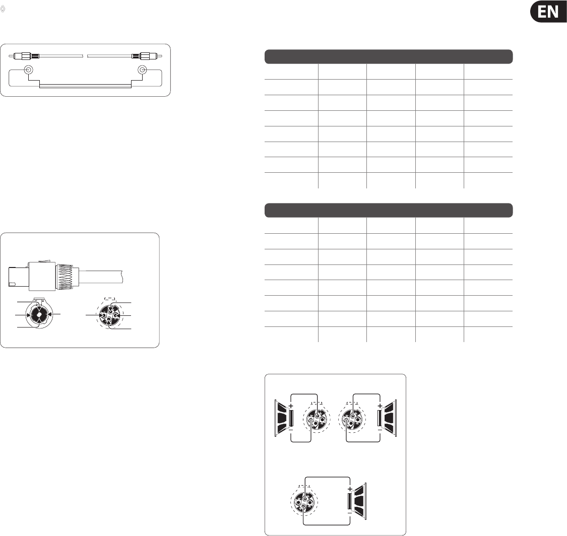
Fig. 4.5: RCA cable
shield sleevesleeve
tip tip
4.3 Loudspeaker connection
Your PMP mixer is equipped with high-quality twist-lock professional style
loudspeaker connectors, which ensure safe and trouble-free operation.
Thisconnector was especially developed for high-power loudspeakers. Once it is
plugged in, it safely locks into position and cannot be accidentally disengaged.
Itprevents the occurrence of electrical shock and ensures the correct polarity.
Each of the connectors carries only the assigned single signal (see tab. 4.1/g. 4.7
and the information on the rear panel of the power mixer).
Fig. 4.6: Professional twist-lock style connector
1-
2-
2+
1+
1- 2-
2+
1+
front view rear view
Professional speaker connector
(compatible with Neutrik Speakon connectors)
Please be sure to only use professional locking-style speaker cables (type NL4FC).
Please check the pin connections of your loudspeakers and cables depending on
the EUROPOWER speaker output you choose.
EUROPOWER PMP980S/PMP1680S
OUPUT A 1+ 1- 2+ 2-
MAIN L POS NEG – –
MON POS NEG – –
OUTPUT B – – POS NEG
OUTPUT B 1+ 1- 2+ 2-
MAIN R POS NEG – –
MONO POS NEG – –
BRIDGE POS – NEG –
EUROPOWER PMP960M
OUTPUT A 1+ 1- 2+ 2-
MAIN MONO POS NEG – –
MON POS NEG – –
BRIDGE ––––
OUTPUT B 1+ 1- 2+ 2-
MAIN MONO POS NEG – –
MAIN POS NEG – –
BRIDGE POS – NEG –
Tab 4.1: Pin connections of loudspeaker connectors
OUTPUT B
BRIDGE
1+
1+
2+
1+
1- 1-
8 Ω
4 Ω
8 Ω
4 Ω
16 Ω
8 Ω
OUTPUT B
Fig. 4.7: Connector assignment
10 EUROPOWER PMP1680S/PMP980S/PMP960M User Manual
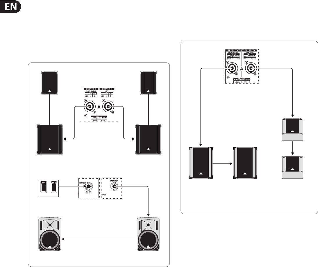
5. Wiring Examples
For stereo operation the POWER AMP switch (28) of the PMP980S/PMP1680S
must be set to its upper position (MAIN L/MAIN R). Outputs A and B deliver
the stereo main signal to the P.A. speakers. Two active speakers, wired in
parallel, are connected to the preamp monitor output. They are used as
on-stage monitor speakers. The eects processors can be switched on and
o with a dual footswitch. This set-up is not possible with the PMP960M
(nostereooperationpossible).
Loudspeaker (F.O.H. mix)
PMP1680S
2 x BEHRINGER EUROLIVE
Stack (B1800X & B1220, both passive)
Loudspeaker connection (monitor mix)
2 x BEHRINGER B215A (active)
PMP1680S Front Panel
(excerpt)
Dual footswitch
Fig. 5.1: EUROPOWER mixer as a stereo amplier (example)
Both the PMP980S/PMP1680S and the PMP960M can be set-up for dual mono
operations. The POWER AMP switch (28) must be set to its lower (PMP960M)
orcenter position (PMP980S/PMP1680S). The two loudspeaker outputs
provide the main and monitor signals independently of each other and to two
loudspeakers each, which are wired in parallel.
Loudspeaker connection for F.O.H and
monitor mix (mono)
PMP960M Rear Panel
(excerpt)
2 x BEHRINGER
EUROLIVE F1520
(passive)
2 x BEHRINGER EUROLIVE B1520
(passive)
Fig. 5.2: EUROPOWER as a dual mono amplier (example)
11 EUROPOWER PMP1680S/PMP980S/PMP960M User Manual
This illustration shows just one example of how the channels of your power mixer
can be used, including the connection of mono and stereo sources, and the tape
ins and outs recording the mix signal or playing back external signals.
EUROPOWER PMP1680S
Stereo channel 7/8
Dat recorder
Electric
guitar
V-AMP2
Keyboard
Vocal mics
Electric
bass
DI box
Mono
channel 5
Mono
channels 1-4 Mono
channel 6
Tape In/Out
Fig. 5.3: Standard set-up (example)
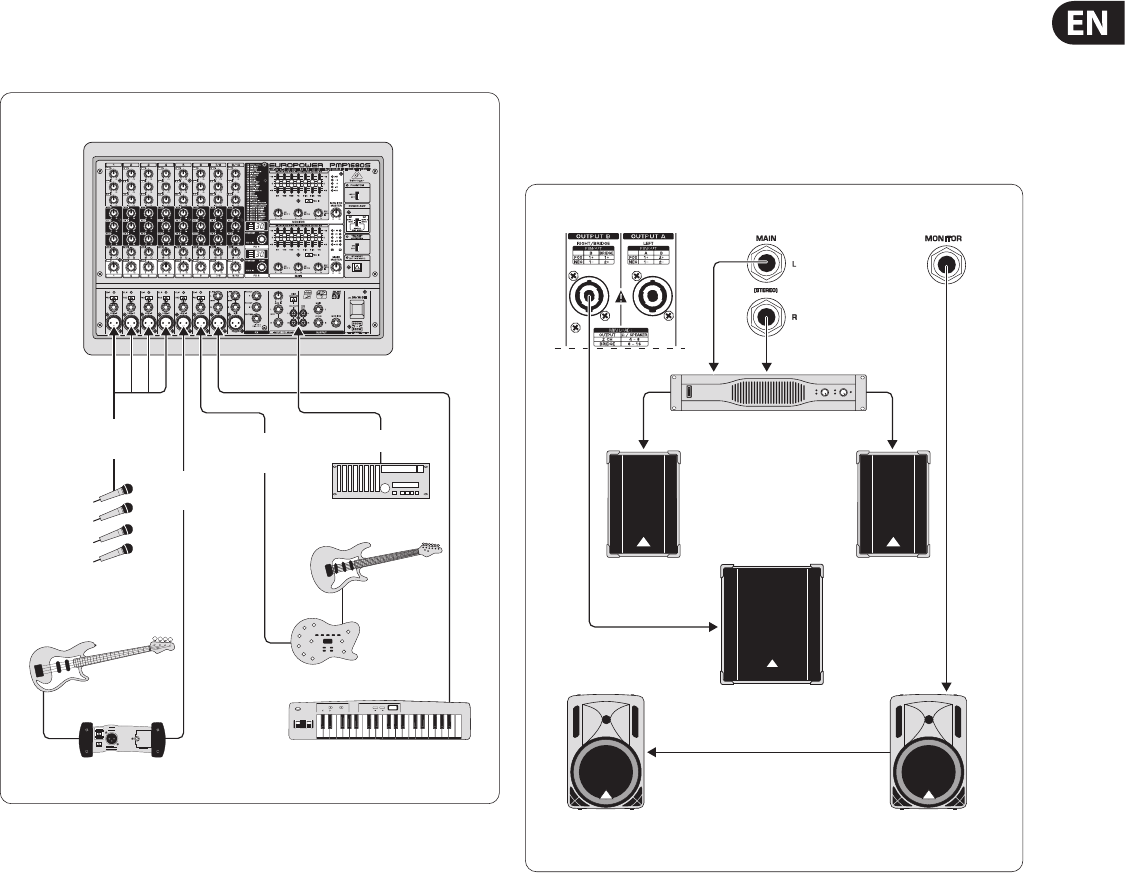
One example of how to use your power mixer with a subwoofer in bridged mono
mode. The illustration shows the PMP1680S with a subwoofer connected to
OUTPUT B that will receive the full (bridged) output power. A separate stereo
power amp (BEHRINGER EUROPOWER EP2000) for the stereo main P.A. signal is
connected to the Pre Amp Main outputs. The Pre Amp monitor output is wired
to active speakers on the stage. This application can also be realized with the
PMP960M, except for the main P.A. signal, which would be mono.
Subwoofer
EUROLIVE
B1220 PRO
EUROLIVE
B1800X PRO Subwoofer
2 x BEHRINGER B215A
(active)
F.O.H. mix Monitor mix
EUROPOWER EP1500
Fig. 5.4: EUROPOWER in bridged mono mode

12 EUROPOWER PMP1680S/PMP980S/PMP960M User Manual
6. Specications
Microphone Inputs
Type XLR, electronically balanced input circuit
Mic E.I.N. (20 Hz - 20 kHz)
@ 0 Ohm source resistance -112 dB / 114 dB A-weighted
@ 50 Ohm source resistance -112 dB / 114 dB A-weighted
@ 150 Ohm source resistance -112 dB / 114 dB A-weighted
Frequency response < 10 Hz - 200 kHz (-1 dB)
< 10 Hz - > 200 kHz (-3 dB)
Gain +30 dB, +10 dB with pad
Max. input level +12 dBu @ +10 dB gain
Impedance approx. 2.2 kOhm balanced /
approx. 1.1 kOhm unbalanced
Signal-to-noise ratio 110 dB / 114 dB A-weighted
(0 dBu In @ +10 dB gain)
Noise (THD + N) 0.001% / 0.0007% A-weighted
Mono Line Inputs
Type ¼" TS connectors, balanced
Impedance approx. 20 kOhm, balanced
Max. input level +21 dBu
Stereo Line Inputs
PMP980S/PMP1680S
Type ¼" TRS connectors, unbalanced
Impedance approx. 100 kOhm, unbalanced
Max. input level +21 dBu
Equalizer
Low 80 Hz / +/-15 dB
Mid 2.5 kHz / +/-15 dB
High 12 kHz / +/-15 dB
CD/TAPE Input
Type RCA
Impedance approx. 10 kOhm
Preamp Outputs
MAIN
Type ¼" TS connectors, unbalanced
Impedance approx. 150 Ohm, unbalanced
Max. output level +21 dBu
MONITOR
Type ¼" TS connectors, unbalanced
Impedance approx. 150 Ohm, unbalanced
Max. output level +21 dBu
Stereo Outputs
PMP960M
Type RCA, mono output
Impedance approx. 1 kOhm
Max. input level +21 dBu
PMP980S/PMP1680S
Type ¼" TRS connectors, unbalanced
Impedance approx. 150 Ohm, unbalanced
Max. input level +21 dBu
Type RCA
Impedance approx. 1 kOhm
Max. input level +21 dBu
Main Mix System Data
Noise:
MAIN MIX @ -∞ -102 dB/-106 dB A-weighted
Channel fader -∞
MAIN MIX @ 0 dB -88 dB/-91 dB A-weighted
Channel fader -∞
MAIN MIX @ 0 dB -84 dB/-86 dB A-weighted
Channel fader @ 0 dB
Loudspeaker Outputs
Type Neutrik Speakon-compatible connector
Load impedance:
MAIN L/R 4 - 8 Ohm
MONITOR/MAIN MONO 4 - 8 Ohm
MAIN MONO/MAIN MONO 4 - 8 Ohm
BRIDGE 8 - 16 Ohm

13 EUROPOWER PMP1680S/PMP980S/PMP960M User Manual
DSP
Converter 24-bit Delta-Sigma,
64/128-times oversampling
Dynamics D/A 90 dB
Sampling rate 40 kHz
Delay Time max. 5 secs
Signal run time approx. 1.5 ms
(Line In > Line Out)
Display
PMP960M
Type 2-digit, 7-segment LED
PMP980S/PMP1680S
Type 2 x 2-digit, 7-segment LED
Output Power
PMP960M/PMP980S
RMS @ 1% THD (sine wave), both channels driven:
8 Ohm per channel 160 W
4 Ohm per channel 300 W
RMS @ 1% THD (sine wave), bridged mode:
8 Ohm 600 W
Peak Power, both channels driven:
8 Ohm per channel 260 W
4 Ohm per channel 450 W
Peak Power, bridged mode:
8 Ohm 900 W
PMP1680S
RMS @ 1% THD (sine wave), both channels driven:
8 Ohm per channel 300 W
4 Ohm per channel 600 W
RMS @ 1% THD (sine wave), bridged mode:
8 Ohm 1200 W
Peak Power, both channels driven:
8 Ohm per channel 400 W
4 Ohm per channel 800 W
Peak Power, bridged mode:
8 Ohm 1600 W
Fuses
PMP1680S
100 - 120 V~, 50/60 Hz T 10 A H 250 V
220 - 240 V~, 50/60 Hz T 6.3 A H 250 V
Power Consumption
Power consumption 1000 W
Mains connector IEC standard receptacle
Dimensions/Weight
Dimensions (H x W x D) approx. 315 x 460 x 220 mm
(approx. 12 / x 18 / x 8 /")
PMP960M
Weight 8.5 kg (18 / lbs)
PMP980S
Weight 9.4 kg (20 / lbs)
PMP1680S
Weight 9.9 kg (21 / lbs)
BEHRINGER is constantly striving to maintain the highest professional standards. As a result of these efforts,
modifications may be made from time to time to existing productswithout prior notice. Specifications and
appearance may differ from those listed or illustrated.

14 EUROPOWER PMP1680S/PMP980S/PMP960M User Manual
FEDERAL COMMUNICATIONS
COMMISSION COMPLIANCE
INFORMATION
Responsible Party Name: MUSIC Group Services US Inc.
Address: 18912 North Creek Parkway,
Suite 200 Bothell, WA 98011,
USA
Phone Number: +1 425 672 0816
EUROPOWER PMP1680S/PMP980S/PMP960M
complies with the FCC rules as mentioned in the followingparagraph:
This equipment has been tested and found to comply with the limits for a ClassB
digital device, pursuant to part 15 of the FCC Rules. These limits are designed
to provide reasonable protection against harmful interference in a residential
installation. This equipment generates, uses and can radiate radio frequency
energy and, if not installed and used in accordance with the instructions, may cause
harmful interference to radio communications. However, there is no guarantee that
interference will not occur in a particular installation. If this equipment does cause
harmful interference to radio or television reception, which can be determined
by turning the equipment o and on, the user is encouraged to try to correct the
interference by one or more of the followingmeasures:
• Reorient or relocate the receiving antenna.
• Increase the separation between the equipment and receiver.
• Connect the equipment into an outlet on a circuit dierent from that to which the
receiver is connected.
• Consult the dealer or an experienced radio/TV technician forhelp.
This device complies with Part 15 of the FCC rules. Operation is subject to the
following two conditions:
(1) this device may not cause harmful interference, and
(2) this device must accept any interference received, including interference that may
cause undesired operation.
Important information:
Changes or modications to the equipment not expressly approved by MUSIC Group
can void the user’s authority to use the equipment.
EUROPOWER
PMP1680S/PMP980S/PMP960M

We Hear You
