Beijing GODA Instruments GDRD5Y6YD Pulse Radar Level Instrument User Manual FCC for GDRD53
Beijing GODA Instruments Co., LTD. Pulse Radar Level Instrument FCC for GDRD53
Users Manual
Beijing GODA Instruments Co.,Ltd.
北京古大仪表有限公司
Level Measurement Expert
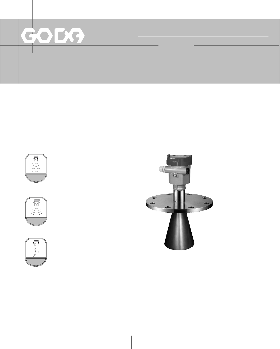
6GHz Pulse Radar Level Instrument

Table of Contents
1 For your safety...... ............... ....1
2 Measurement Principle ................ ...2
3 Mounting Requirement................. ...3
4 Electrical Connection.................. ....9
6 Adjustment Instructions................. . .11
9 Selection & Ordering Information............ 14
1
1.For your safety
All operations described in this operating instructions manual must be carried out ouly by trained
specialist personnel authorised by the plant operator.
During work on and with the device the required personal protective equipment must always be
worn.
Operational reliability is ensured only if the instrument is properly used according to the
specifications in the operating instructions manual as well as possible supplementary instructions.
This device complied with Part 15 of the FCC Rules. Operation is subject to the following
two conditions:
(1)this device may not cause harmful interference, and
(2)this device must accept any interference received, including interference that may
cause undesired operation.
Changes or modifications not expressly approved by the manufacturer could void the user's
authority to operate the equipment.
Authorised personal
Appropriate use
FCC Certification
Warning: User must keep a safety distance of at least 20cm from the antenna.
NOTE: This equipment has been tested and found to comply with the limits for a Class A digital
device, pursuant to part 15 of the FCC Rules. These limits are designed to provide reasonable
protection against harmful interference when the equipment is operated in a commercial
environment. This equipment generates, uses, and can radiate radio frequency energy and, if
not installed and used in accordance with the instruction manual, may cause harmful interference
to radio communications. Operation of this equipment in a residential area is likely to cause
harmful interference in which case the user will be required to correct the interference at his own
expense.
2.Measurement Principle
Principle
Features
The extremely narrow microwave pulse emitted by the antenna on radar level instrument
can travel at the speed of light and part of its energy, which is reflected off the surface of
target medium, is received by the very same antenna. The time lapse between pulse
emission and reception by the antenna is proportional to the distance between the surface
of target medium and the reference point on antenna. However, due to the fact that the
electromagnetic wave is transmitted at extremely high speed, which leads to the tiny time
lapse (nanosecond level) and makes it difficult to be identified,GDRD5X series of radar
level instrument have adopted a special demodulation technology, enabling itself to detect
the time lapse between pulse emission and reception correctly, and eventually generate
accurate measurement result.
Equipped with advanced microprocessor and unique EchoDiscovery echo processing
technology, the radar level instrument can be used under various hazardous process
conditions.
The false echo storage function enables the instrument to detect the true echo with the
presence of multiple false echoes and eventually generate accurate measurement results.
There are multiple options available in choosing various process connection and detection
component, which enables GDRD5X series radar level instrument to be applied in a broad
array of hazardous applications, such as high temperature, high pressure, small dielectric
constant and so on.
The guided wave radar level instrument, with pulses as its working tool and extremely low
emission power, can be mounted on various metal or nonmetal vessels, harmless towards
the environment and human beings.
2
There is a certain existing beam angle while the antenna transmitting microwave pulses. There should beno barriers
between the lower edge of antenna and surface of measuredmedium. Therefore it is highly recommended to avoid
facilities inside vessels, such asladders, limit switches, heating spirals, struts and etc, during the mounting process.
“False echo learning” must be carried out during the installation in this case.Furthermore, microwave beams must
NOT intersect the filling streams. Be cautions duringthe installation: the highest level of target medium must NOT
enter into blanking zone; the instrument must keep certain distance to vessel walls; every possible measure needs
to be taken to position the instrument so that the direction of antenna emission is perpendicular to the surface of
measured medium. The installation of instruments in xplosion proof area must abide by relevant local or federal
safety regulations. Aluminum housing should be used for intrinsically safe explosion proof version, which is also
applicable in explosion proof areas. The instrument must be connected with ground in this case.
Note:The highest level of measured medium must not enter into vlanking zone while
radar level measurement instrument is in operation.
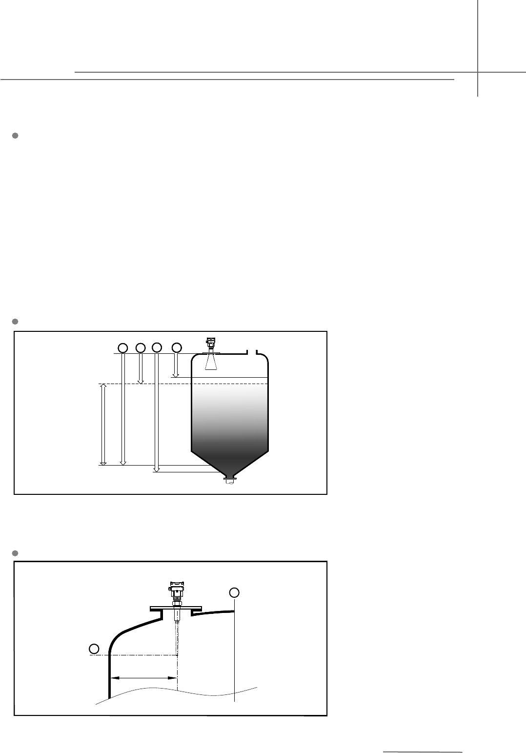
1.Reference Plane
2.Center of Vessel or Symmetrical
Axis
Minium distance of 500mm
between instrument and vessel
wall during installation
>500mm
1
2
3
3.Mounting Requirements
Basic Requirements
The reference plane is the
thread or flange surface
100%
0%
11111111
2222
33
3
33
4
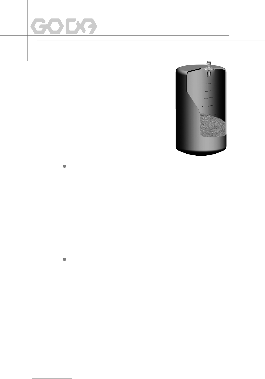
Illustrations
Mounting Position
1. Blanking Zone(menu1.9)
2. Empty(menu1.8)
3. Max. Adjustment(menu1.2)
4. Min. Adjustment(menu1.1)
6GHz Pulse Radar Level Instrument
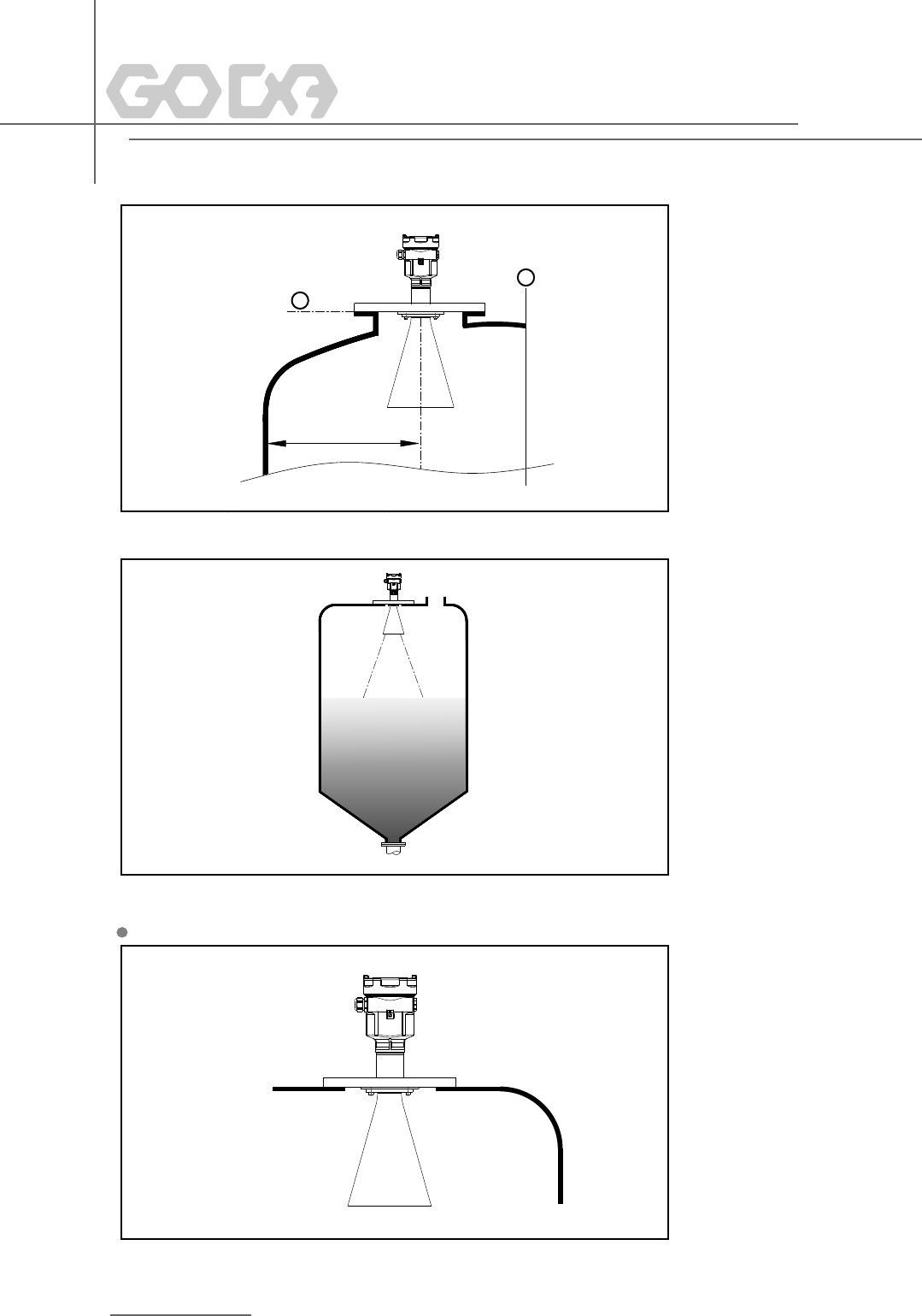
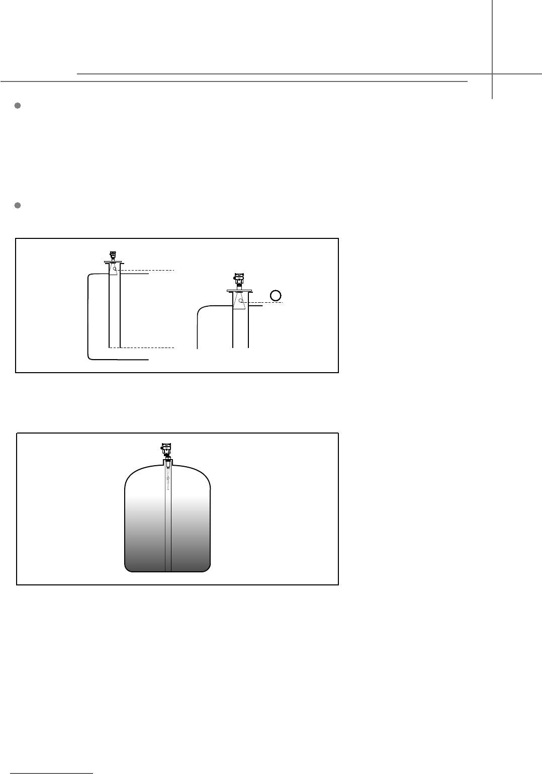
The best mounting position for a
conical vessel with flat top is the
center of its top, as the effective
measurement can reach the
bottom of vessel.
In order to avoid dampness under
outdoor or humid indoor conditions
or for those instruments mounted
on cooling/heating vessels, seal
rings used on cables should be
screwed tight, plus the cable must
be bended downward outside
cable entry, indicated on the
diagram below
>500mm
1
2
Damp-proof
4
1.Reference Plane
2.Center of Vessel or Symmetrical
Axis
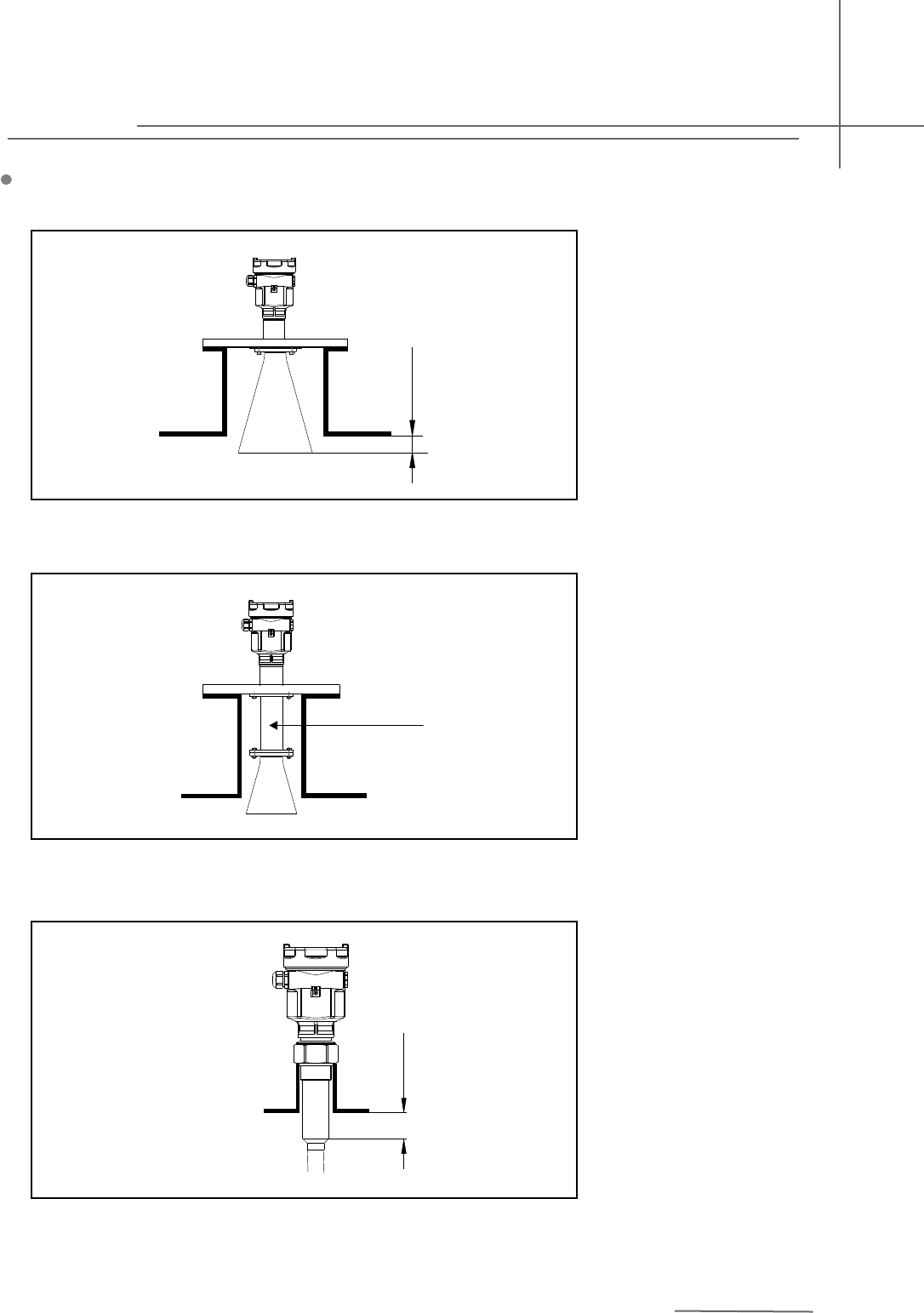
Socket
The transducer end must at
least protrude 10mm out of
socket.
Horn Antenna
You are advused to use antenna
extension if the antenna is shorter
than socket.
The working part of antenna ,ie. the
cone-shaped body of antenna must
be fully exposed from the socekt. In
orderto meet the application requirement
of various sockets, different radar
level instrumentsof various sockets,
different radar level instruments of
variable length are available for
customers to choose from(see Chapter
6 Dimensional Drawings).
Rod Antenna
>10mm
Antenna Extension
Antenna Extension
5
6GHz Pulse Radar Level Instrument
>20mm
12
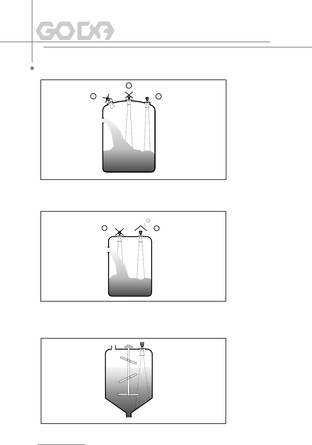
1.Wrong: Mount the instrument
in/above filling stream, which
results in the measurement of
filling stream not the target medium.
2.Correct:
1
2
3
1.Wrong: Fail to turn the antenna
prependicular to the surface of
target medium.
2.Wrong:Instruments are mounted
in the center of concave or arched
vassel tops, which results in
multiple echoes.
3.Correct
Rights and Wrongs in Mounting
If there are agitators in vessels,
instrument must be mounted as
far away from agitators as possible.
Once installation completed, a
"false echo learning" should be
carried out while agitators in
motion to eliminate negative
influence caused by false echo
of agitators. You are advised to
opt for installation with standpipe
if foam or wave is generated due
to the action of agitators.
Agitator
6
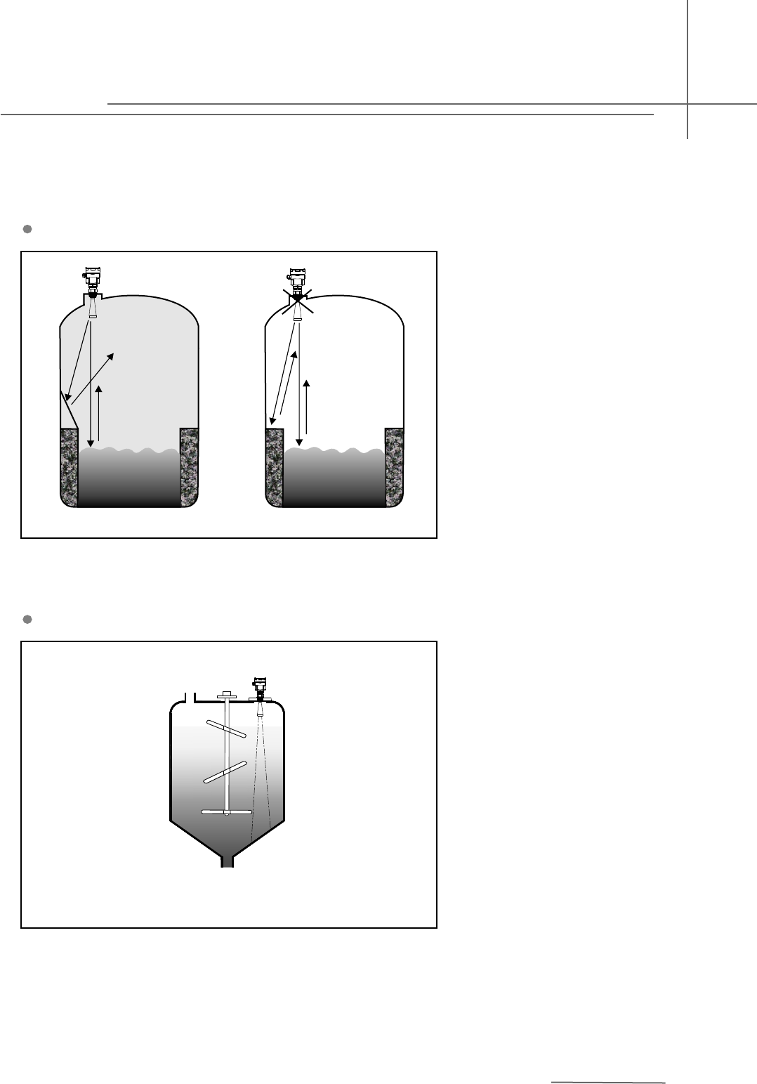
A
Reflection board installation
If there are barriers in vessels, it is
required to mount baffle-board, by
doing this, the echo reflected by the
barrier will be reflected out. And “False
Echo Storage” will be applied.
7
If there are agitators in vessels,
instrument must be mounted as
far away from agitators as possible.
Once installation completed, a
"false echo learning" should be
carried out while agitators in
motion to eliminate negative
influence caused by false echo
of agitators. You are advised to
opt for installation with standpipe
if foam or wave is generated due
to the action of agitators.
Agitator
Pulse Radar Level Instrument
Foam
Due to the action of filling, stirring or other processes inside vessels, dense foams are formed on the surface
of some liquid medium, which could attenuate emitting signals considerably. You are advised to mount the
instrument inside a standpipe or opt for a guided wave radar level instrument if the generation of foam incurs
measurement errors.
Vent hole of diameter 5-10mm
Installation with Standpipe
By using standpipe, the influence of foams can be reduced.
If the measurement is undertaken
by GDRD5X inside a metal standpipe,
the minimum inner diameter of
standpipe should be 50mm. Avoid
large cracks or welding seam when
connecting standpipe. False echo
storage must be carried out as
well in this case.Note: You must
NOT mount instrument inside
standpipe while measuring adhesive
medium.
ma x.
min.
11111111
Installation with a plastic standpipe
can avoid the generation of multiple
false echoes while the instrument
being mounted on the center of
vessel top. You are advised to
use PP or PTFE if the measured
medium is strong acidic or alkaline.
6GHz Pulse Radar Level Instrument
8
9
Power supply and current signal are carried by the same two-wire connection cable.
This equipment is not allowed to be connected to public utility power lines.
See the Technical Specifications of this guide for detailed requirement on power
supply. A safety barrier should be placed between power supply and instrument for
intrinsically safe version.
See the Technical Specifications of this guide for detailed requirement on power supply.
Earth-connected current output can be used for standard version of level instruments,
while the explosion proof version must be operated with a floating current output. Both
instruments and earth terminals should be connected with ground firmly and securely.
Normally you can either choose to connect with the earth terminal on vessel or adjacent
ground in case of plastic vessels.
Standard 2-wire cable with outside diameter of 5...9mm, which assures the seal effect
of cable entry, can be used as feeder cable. You are recommended to use screened
The two ends of shielded cable must be connected with earth terminal. The shielded
cable must be connected with inner earth terminal directly inside the transducer, while
the outside earth terminal on housing must be connected with ground. In the event of
earth-connected current, the shielding side of shielded cable must be connected to
ground potential via a ceramic capacitor (e.g. : 1μF 1500V) in order to dampen the low
frequency grounding current and avoid the disturbance caused by high frequency signals
5 Electrical Connection
Power Supply
General Introduction
20mA/HART(2-Wire)
Cable Connection
Shielding & Grounding
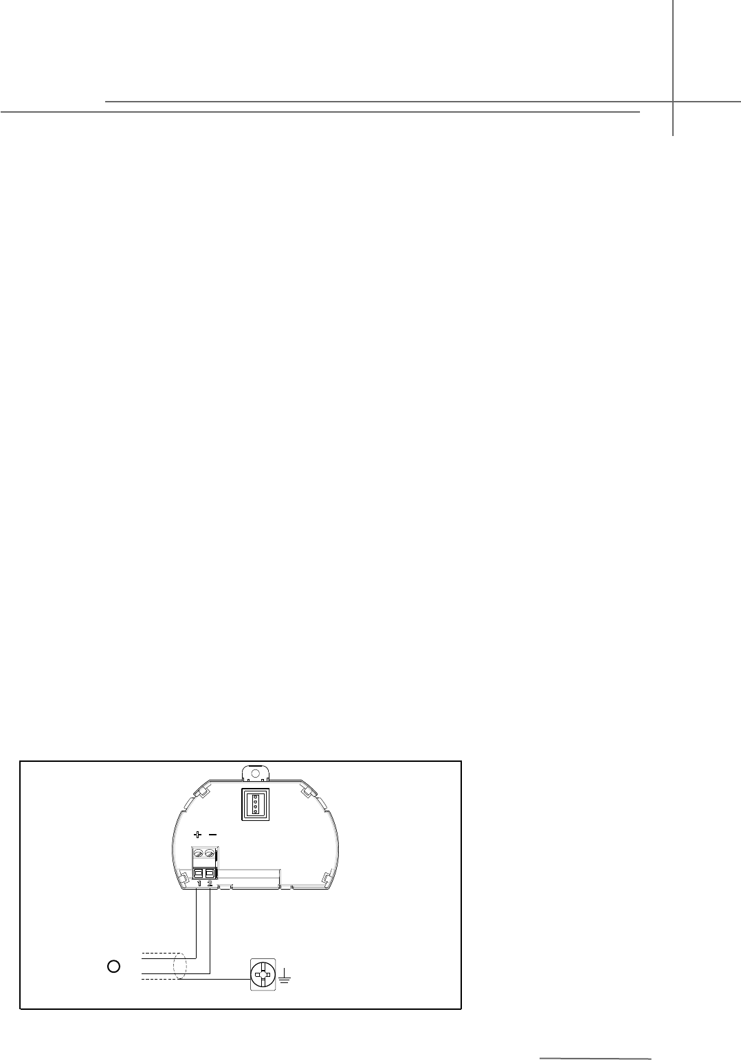
2-wire
Wiring Diagram
2-wire wiring used for HART
1)Power Supply and Signal Output
+
-
1
Pulse Radar Level Instrument
65
321
4
(4~20 ) m A I N ( 4~20)mA OU T
24V OUT 2 4 V IN
FBS-2
COM W AY G O D Awar e
(4~20)mA
65
321
4
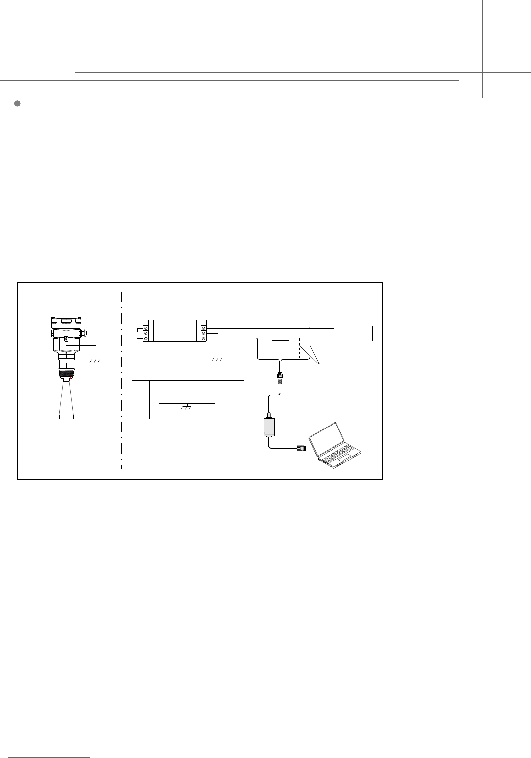
Explosion Proof Connection
This product is an intrinsic safety explosion proof version (Exia ⅡC T6 Ga) with stainless steel housing and
plastic-encapsulated internal structure aimed to prevent sparks resulted from transducer and circuit malfunction
from leaking out. It is applicable for the non-contact continuous level measurement of flammable medium under
the level of explosion proof inferior to Exia ⅡC T6 Ga. You are required to use series (intrinsic safety explosion
proof: [Exia] ⅡC,voltage of power supply: 24V DC±10%,short-circuit current: 114mA,operating current:
4...20mA) of safety barriers, which are supplementary to this product, for the power supply of this product.
All connection cables must be screened with max. length of 500m. Stray capacitor≤0.1μF/Km,stray inductance
≤1mH/Km. The level measurement instrument must be connected to ground potential and unapproved
supplementary devices are not allowed to use.
Explosion Proof Zone None-Explosion-Proof Zone
Adjust with GODAware
choose either one
Pulse Radar Level Instrument
10
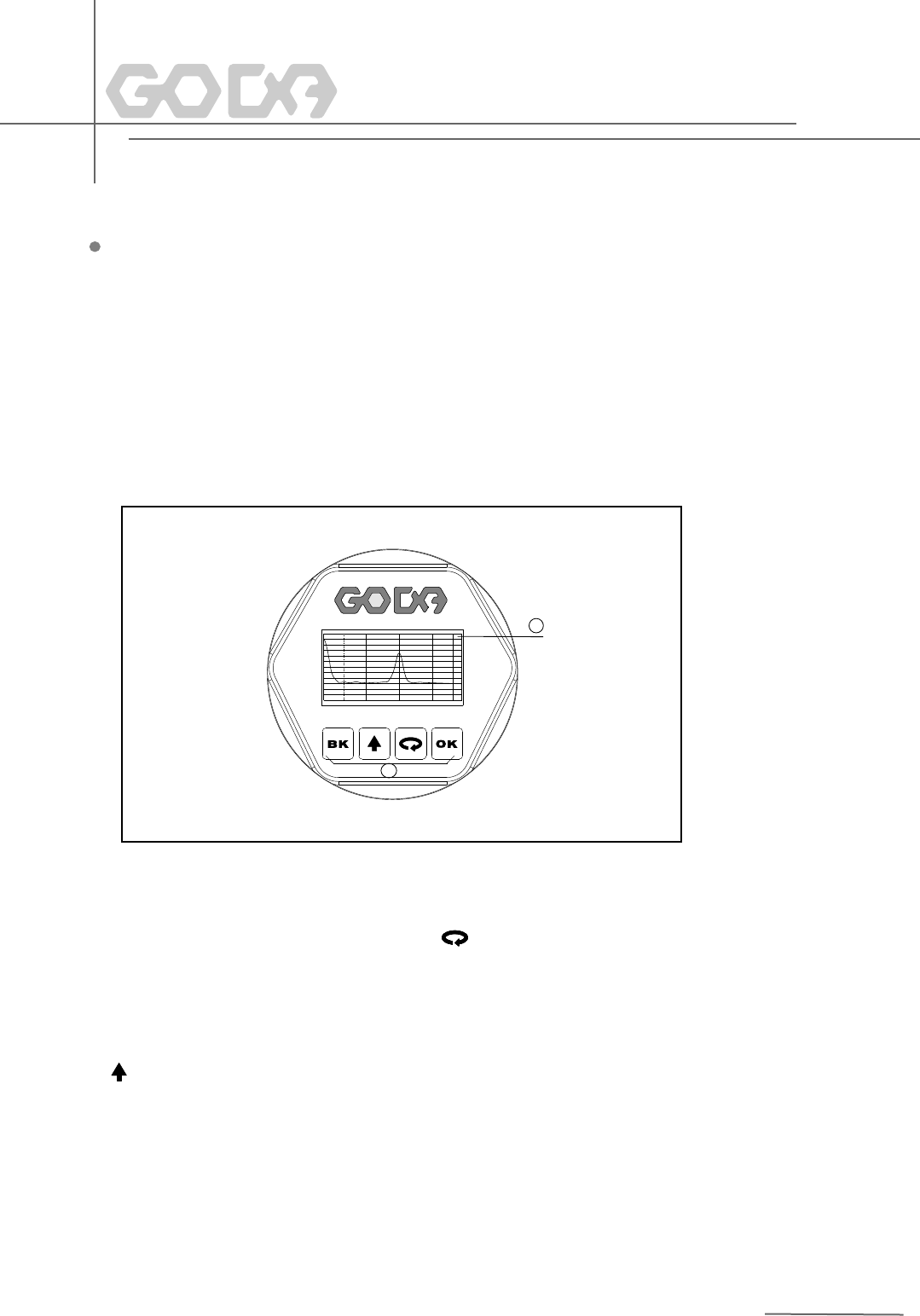
Display/Adjustment Module
1
2
0. 0 0
0
10
20
30
40
50
60
70
80
90
10 0
11 0
12 0
dB
2. 0 0 3. 0 0 4. 0 0 5. 00
1 LCD 2 Adjustment Keypad
1
2
[ ]Keypad
-Enter programming mode;
-Confirm programming options;
-Confirm modifications to parameters.
OK[ ]Keypad
-Choose programming options;
-Choose the digit of parameters to edit;
-Display the contents of parameters.
[ ]Keypad
-Modify parameter values.
[ ]Keypad
-Programming mode exit;
-Return to higher menu level.
Shortcut
[ ]Display Echo wave
KB
KB
6 Adjustment Instructions
Adjustment Methods
Three adjustment methods available for GDRD series :
1.Display/Adjustment Module
2.Adjustment software GODAware
3.HART handheld programmer
ViewPoint is a pluggable display/adjustment module. The adjustment can be done through operating with four
buttons on ViewPoint. Optional menu operation languages are available for selection. ViewPoint is only used for
display after adjustment in that the measurement results can be seen clearly through the glass window.
11
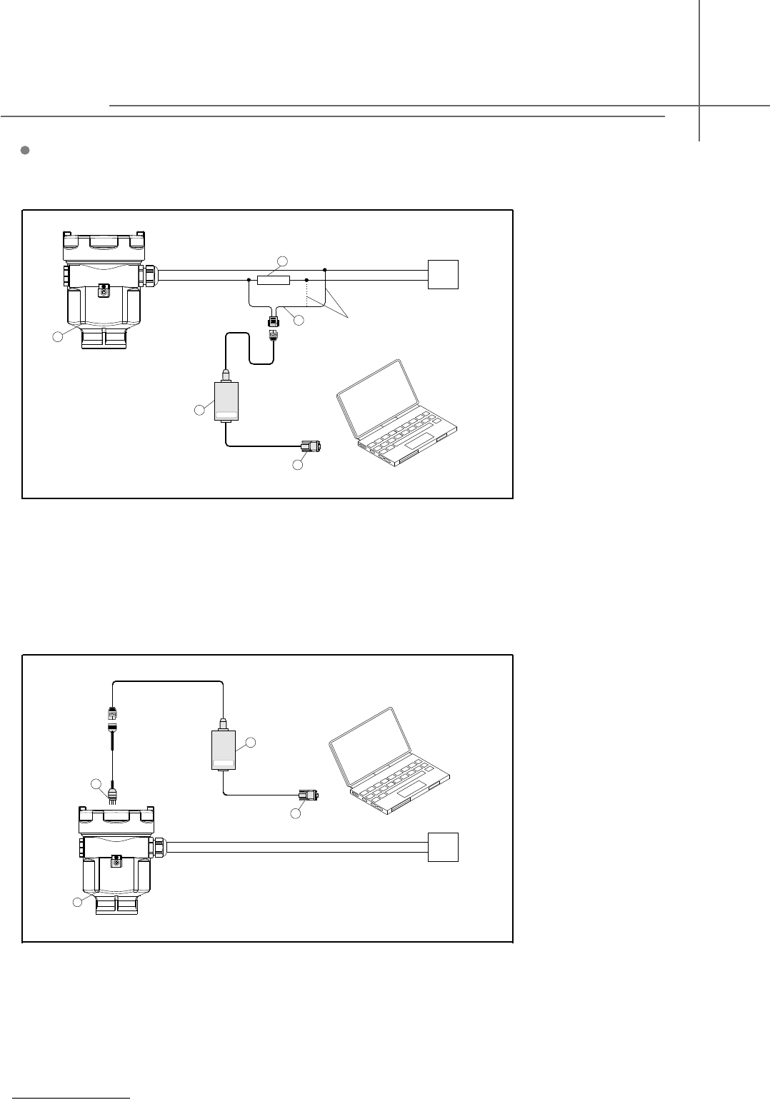
Connect with another unit throuth HART.
1 RS232 Connect Cable/USB port
2 GDRD series
3 HATR pont adapter used on COMWAY convertor
4 250 ohm Resistance
5 COMWAY Convertor
1 RS232 Connect Cable/USB port
2 GDRD series
2
3 I C adapter pont used on MOMWAY convertor
4 COMWAY Convertor
3
4
2
1
+
- DC
COMWAY
GODAware
1
5
2
3
4
+
- DC
COMWAY
GODAware
Choost Either One
2
Connect with another unit throuth I C .
GODAware
Pulse Radar Level Instrument
12
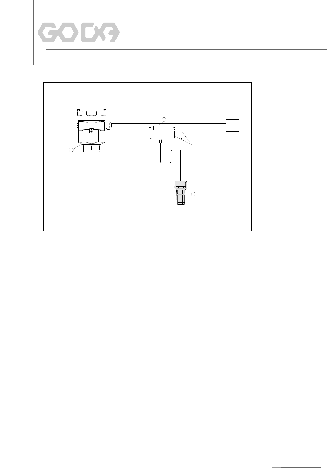
HART Handheld Programmer
Adjust GDRD series with HART Handheld Programmer
1 HART Handheld Programmer
2 GDRD series
3 250 ohm Resistance
2
1
3
+
- DC
Choost Either One
13
GDRD53
(a)Explosion Proof Approval
P Standard
I Intrinsic Safety(Exia IIC T6 Ga)
(b)Shape of Antenna/Material
K Horn Φ100mm Stainless Steel/Internal PFA coating
L Horn Φ150mm Stainless Steel/Internal PFA coating
(c)Antenna Extension
A No
B 200mm
C 500mm
D 1000mm
E 2000mm
X Special Design
(d)Process Connection/Material
FA Flange DN50 PN1.6 Stainless Steel316L(GB/T9119-2000)
FB Flange D80 PN1.6 Stainless Steel316L(GB/T9119-2000)
FC Flange DN100 PN1.6 Stainless Steel316L(GB/T9119-2000)
FD Flange DN150 PN1.6 Stainless Steel316L(GB/T9119-2000)
FE Flange Dn200 PN1.6 Stainless Steel316L(GB/T9119-2000)
YP Special Design
(e)Electronic
B (4~20)mA/HART 2-Wire
(f)Housing
A: Aluminium
G:Stainless Steel
9 Selection & Ordering Information
(g)Cable Entry
M M20x1.5
N ½NPT
(h)Display/Programming
A Yes
X No
(i)Huff
A Yes
X No
14

Beijing GODA Instruments Co.,Ltd.
Edition: GD/201412
Sales Dept Of Beijing GODA Instruments Co., Ltd.
Add: Room1303, Block D, Ocean International Center,
No 62 Middle Of east 4th ring, Chaoyang Dist.,
Beijing,100025, China
(010)59648788( )
(010)59648789
100025
Tel: Ext.8
Fax:
PC: