Beijing TierTime Technology 3DP-12ES UP mini 2 ES User Manual
Beijing TierTime Technology Co. Ltd UP mini 2 ES
UserManual.wiki
>
Beijing TierTime Technology
>
3DP 12ES User Manual
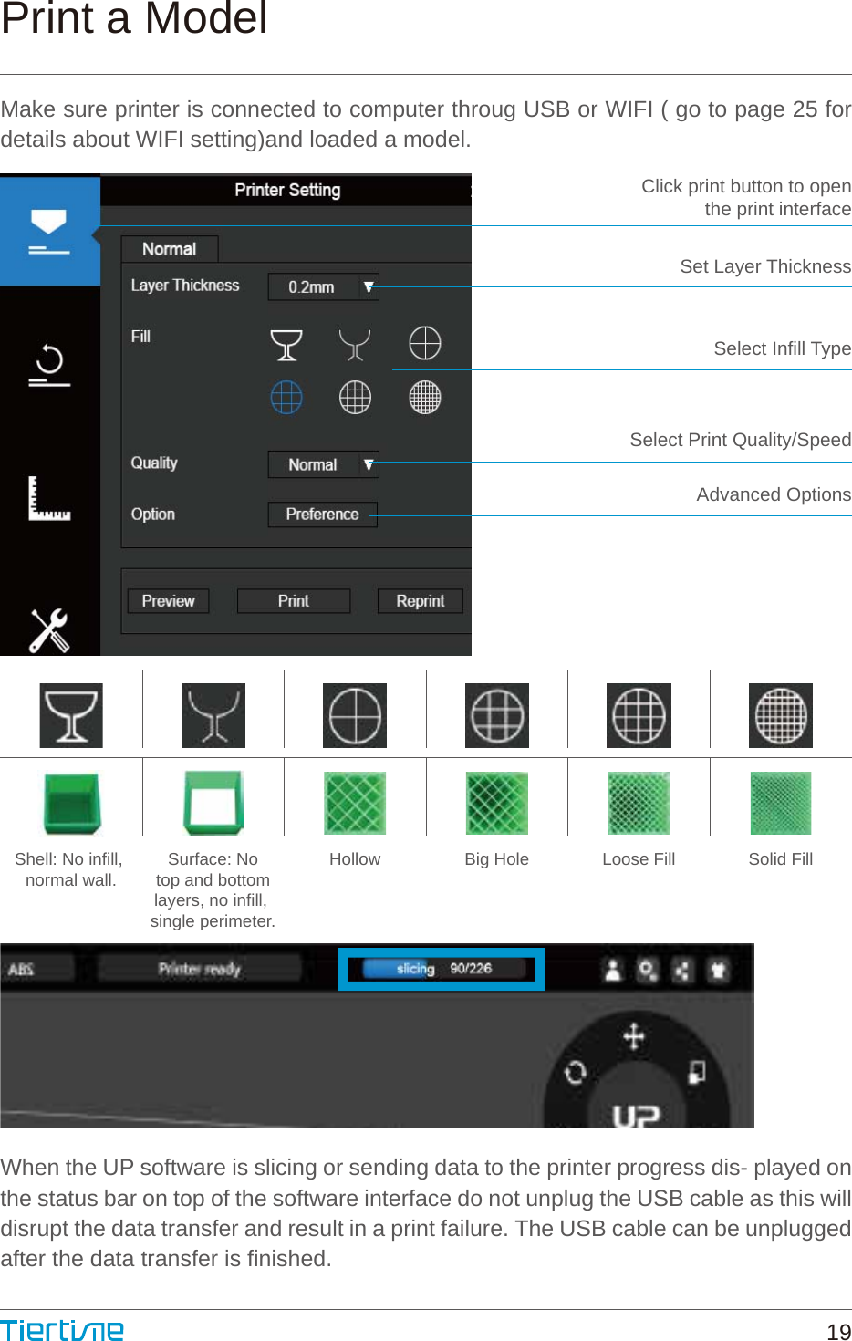
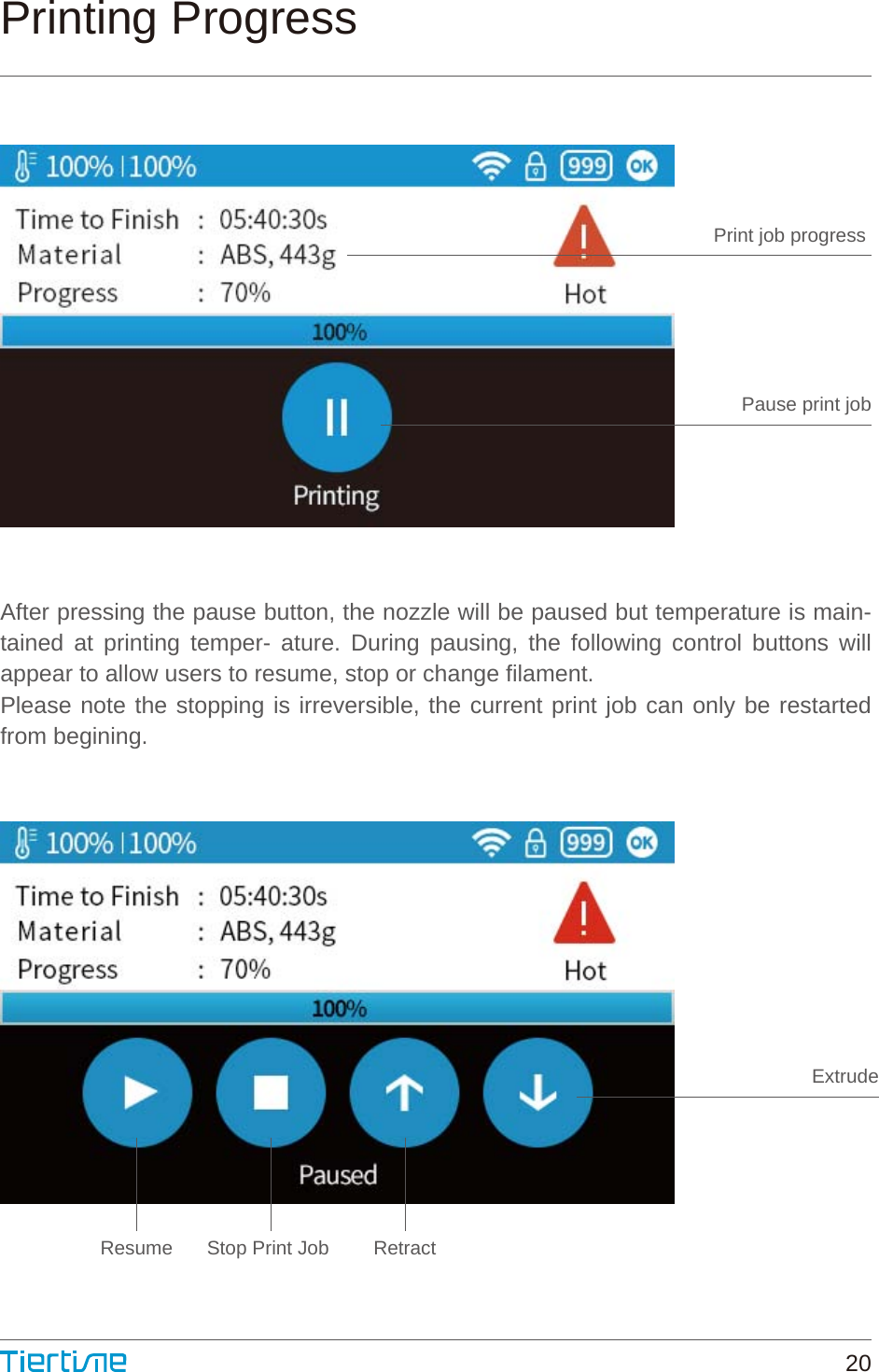
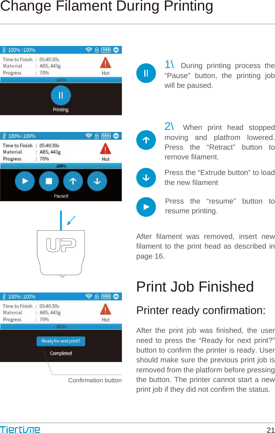
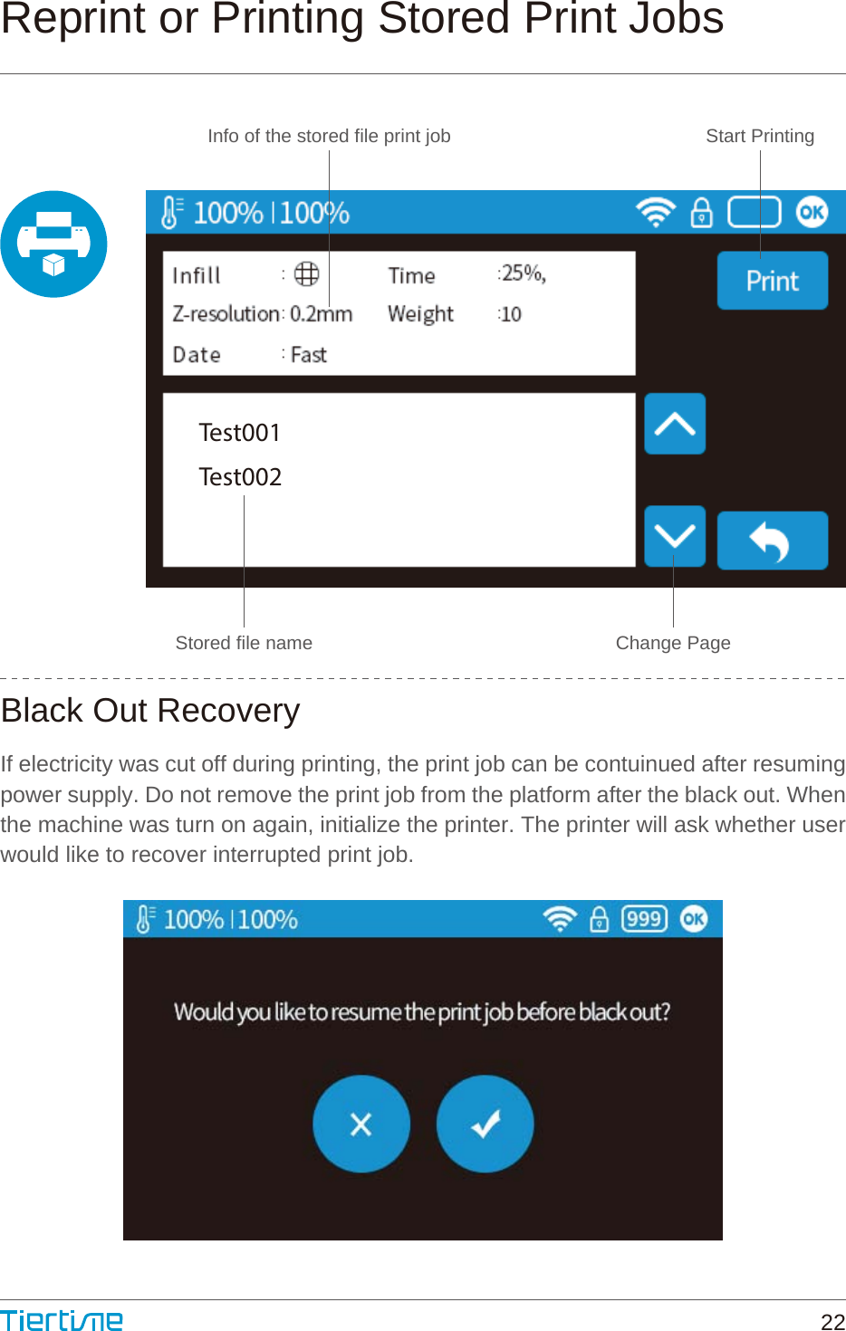
User manual
Navigation menu
Upload a User Manual
Namespaces
Wiki Guide
HTML
PDF
Info
Views
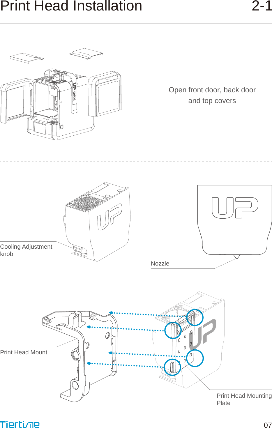
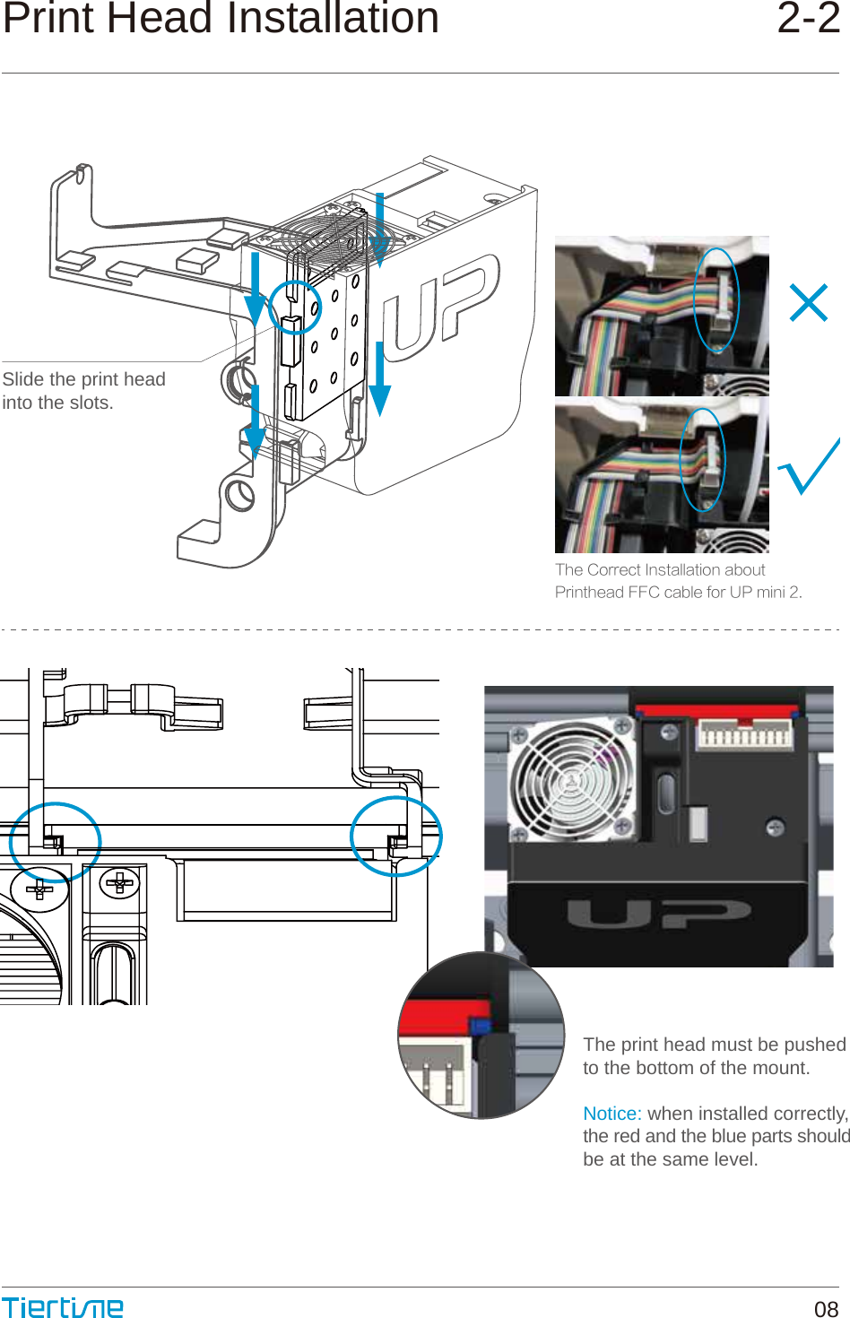
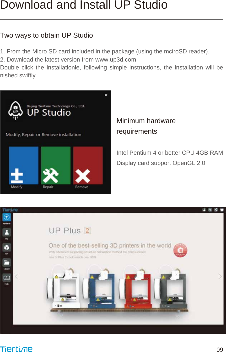
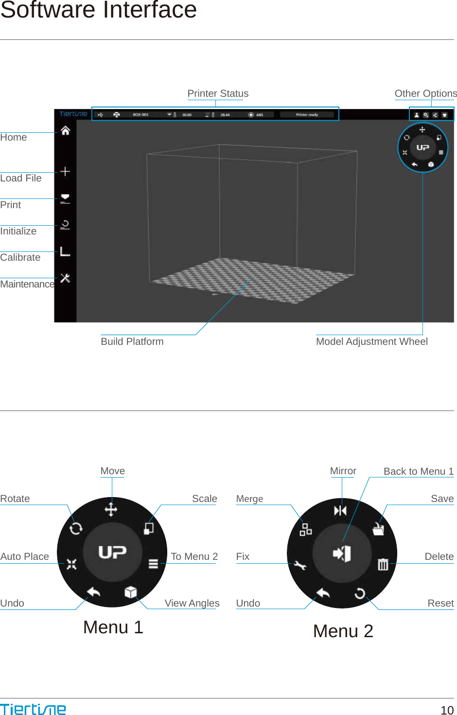
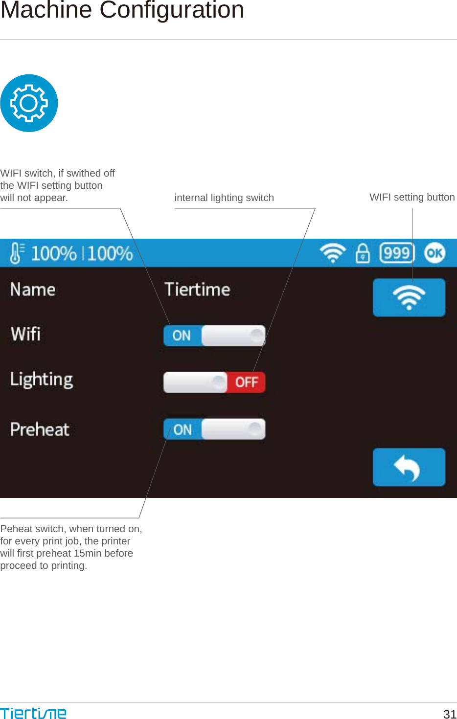
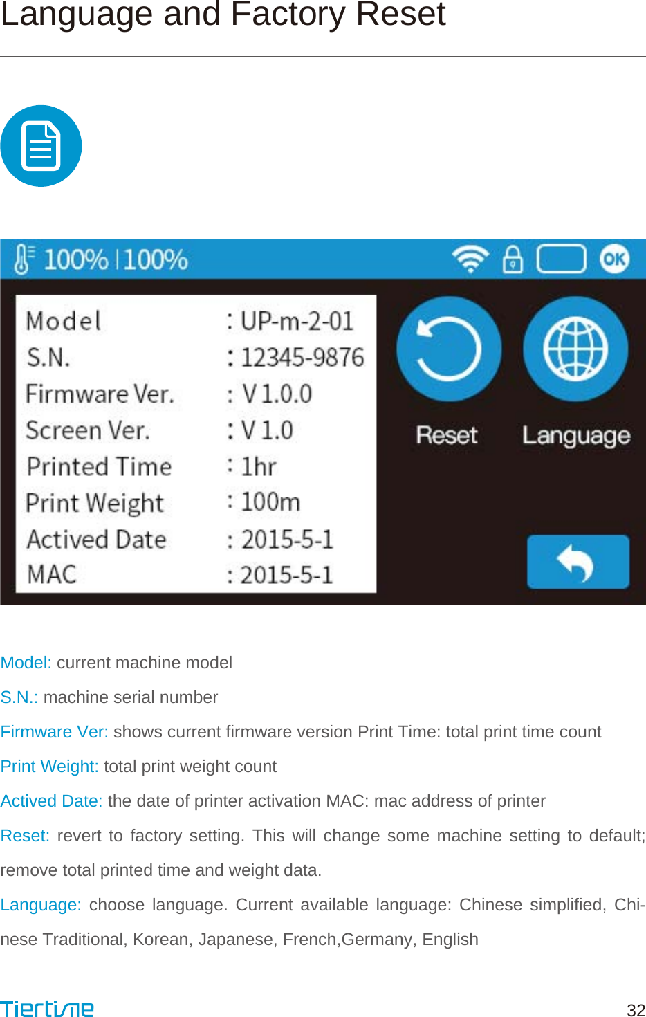
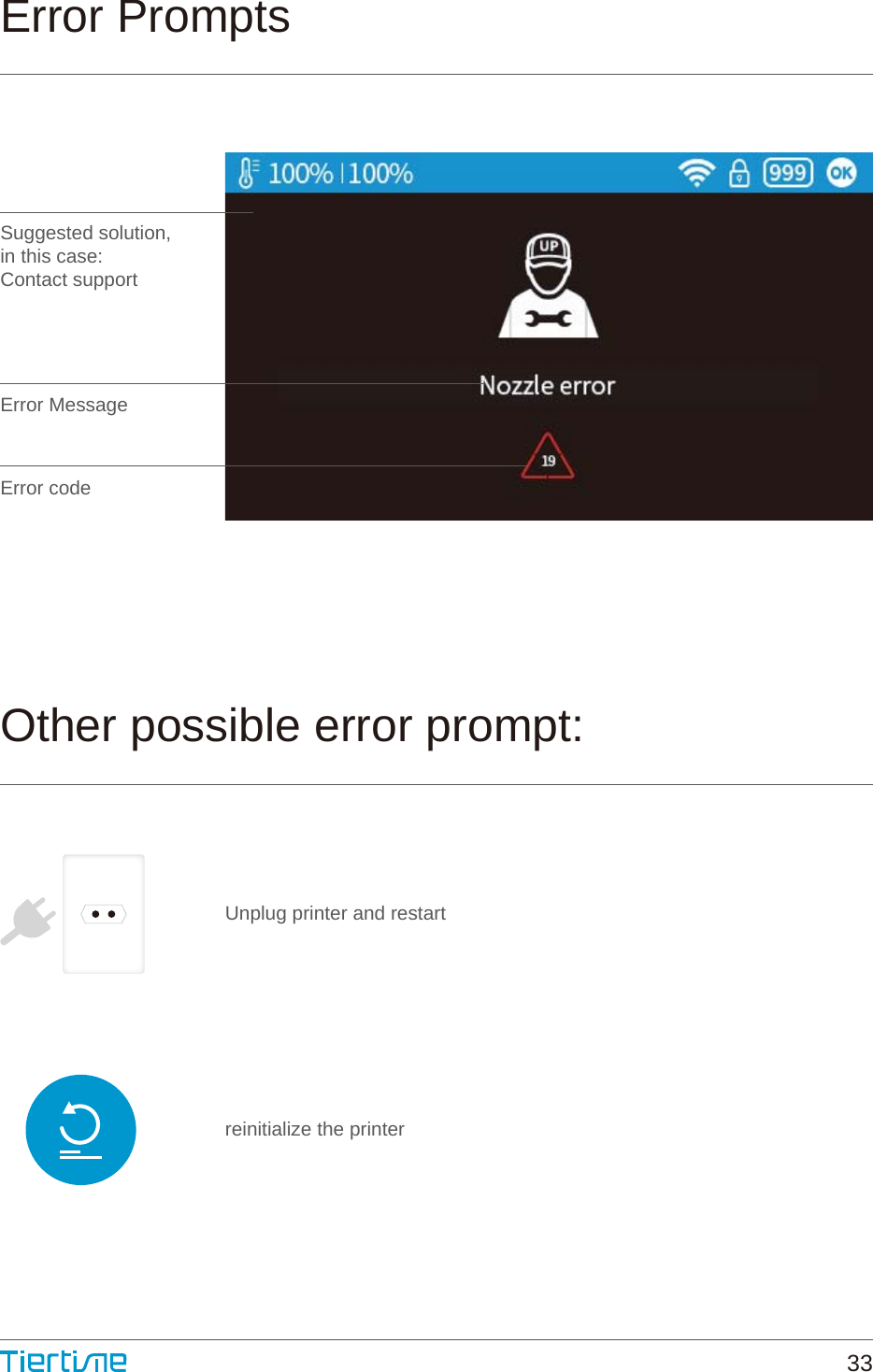
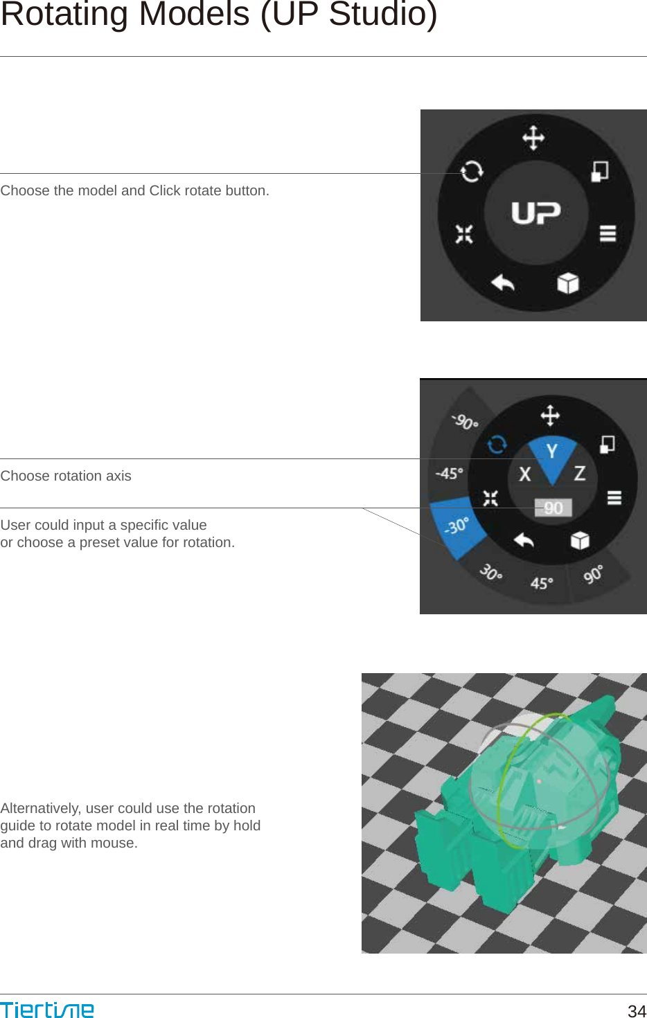
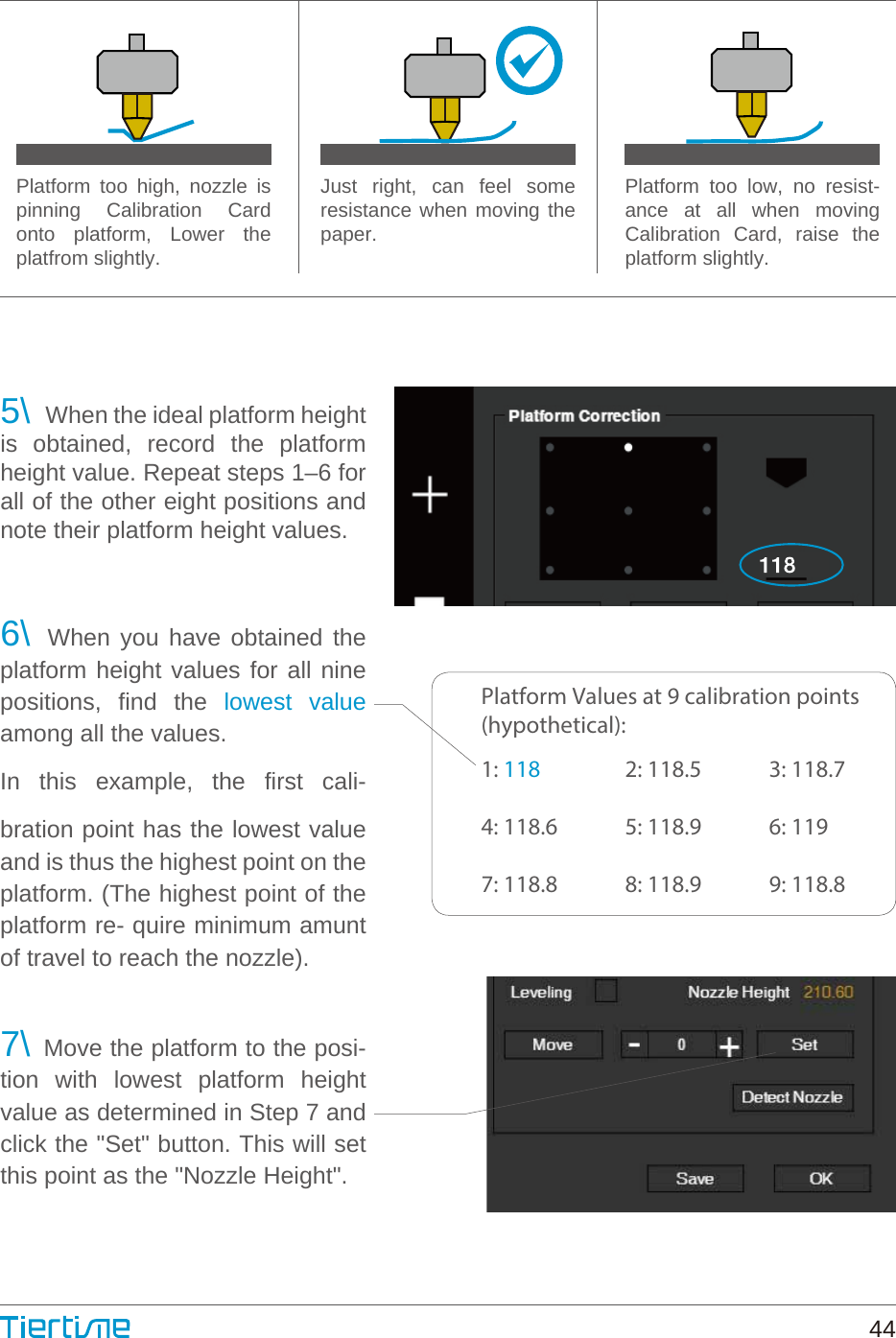
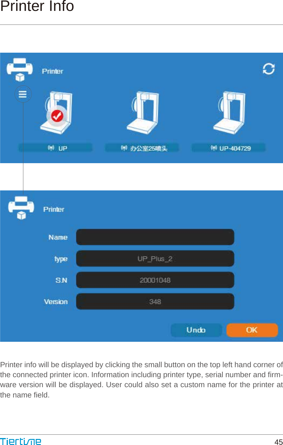
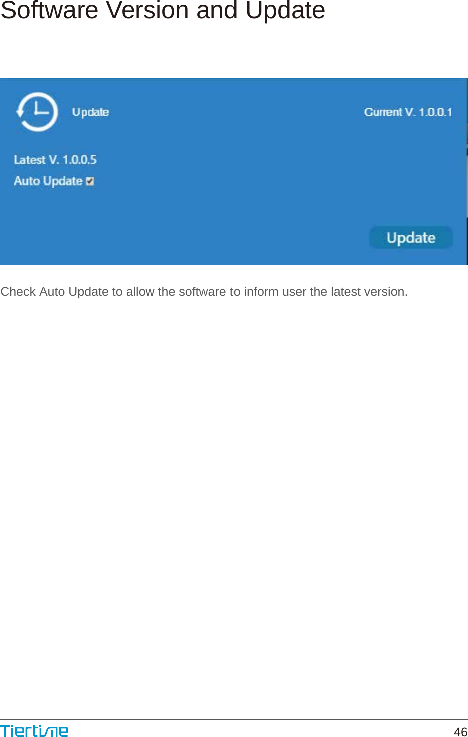
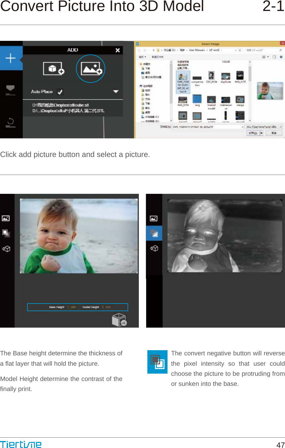
User Manual
Discussion / Help
Navigation