Beijing TierTime Technology 3DP-18 Cetus User Manual
Beijing TierTime Technology Co. Ltd Cetus
User Manual

1
Cetus3D
Cetus3D
Cetus
User Manual V 0.1

2
Cetus3D
Precautions
Printer Body
Accessories
Install Print Head
Installing Build Platform
Installing the Software
Software Interface
Starting UP the Printer
Setting the Nozzle Height
Preparing for Printing
Setting UP Wi-Fi
Product Activation
Loading a Model
Printing a Model
Pausing a Print Job
Rotating a Model
Scaling a Model
Moving a Model
Making Copies
Merging and Saving Models
Printing Preference
Printing Parameters
4
5
6
7
8
9
10
11
12
13
14
18
19
20
21
22
23
24
25
26
27
29
Table of Contents

3
Cetus3D
Using Customized Material Prole
Converting a 2D Picture into a 3D Model
Machine and Software Settings
Printer Info and Naming a Printer
Change Nozzle
30
31
33
34
35
Table of Contents
4
Cetus3D
Cetus 3D printer only works with the power adapter provided by the original manufacturer, otherwise the
machine could become damaged or even cause a re hazard. Keep the power adapter away from water and high
temperature environments.
During printing, the temperature of the nozzle of
Cetus could reach 260°C and the print platform could
reach 100°C. Do not touch these parts with your bare
hands while they are hot—not even with the heat
resistant gloves included with the machine—as the
temperature could damage the gloves and injure
your hands.
Wear goggles when removing the supporting material from models, or detaching models from the print board.
During printing, the nozzle and the print platform
could be moving at high speeds. Do not touch these
parts while they are moving.
When printing with ABS or PLA, the plastics will generate a slight odor. Run the printer in a well-ventilated
environment. We also suggest you put the printer in an environment with a stable temperature as unwanted
cooling could cause adverse eects to the print quality.
When the UP software is sending data to the printer—indicated on the status bar on the left bottom corner of the
software interface with the text "sending layers"—do not unplug the USB cable as this will disrupt the data transfer
and result in a printing failure. The USB cable can be unplugged after the data transfer is nished.
The Cetus's ideal working temperature is between 15°C and 30°C with relative humidity between 20–50%. Users are
recommneded to discharge any static charge from the body before touching the machine to prevent interruption
of printing and any potential damage to the printer.
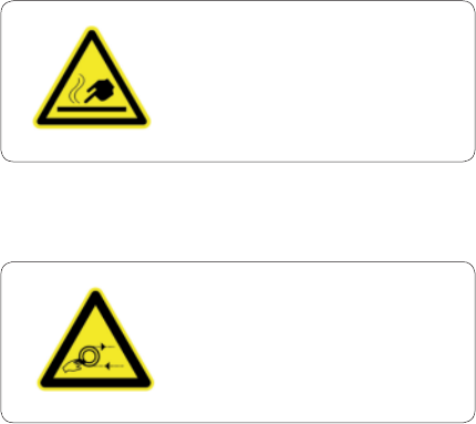
Precautions
Warning label on printer:
High Temperature,
do not touch!
Warning label on printer:
Moving Parts, do not touch!
1
2
3
4
5
6
7
5
Cetus3D
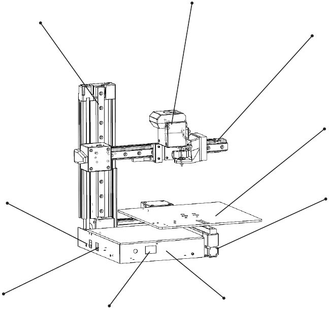
Main Board Case
Build Platform
X-axis
Power
Switch
Y-axis
Print Head
Z-axis
USB Connector
Power
Connector
Printer Body
6
Cetus3D
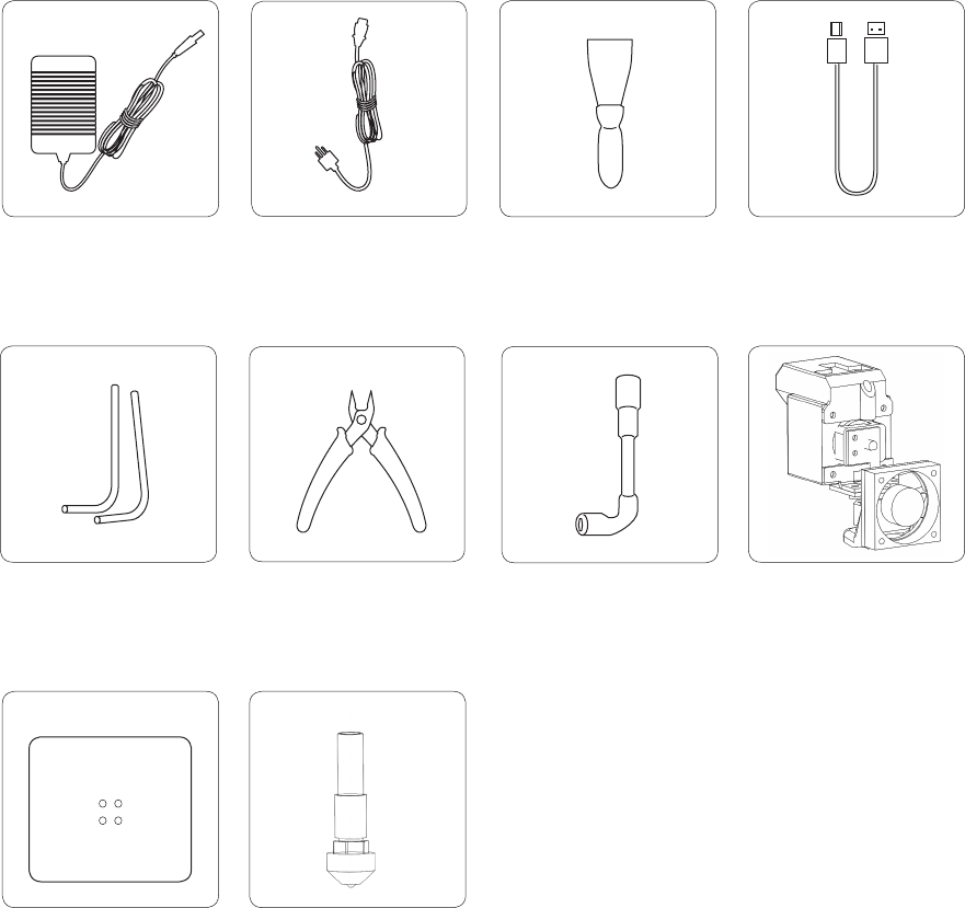
Accessories
Nozzle Wrench Print Head
Plier
Build Plate Nozzles
0.2mm
0.4mm
Hex Keys
2.0mm, 2.5mm
Power Adapter USB CableScraperPower Cable
7
Cetus3D
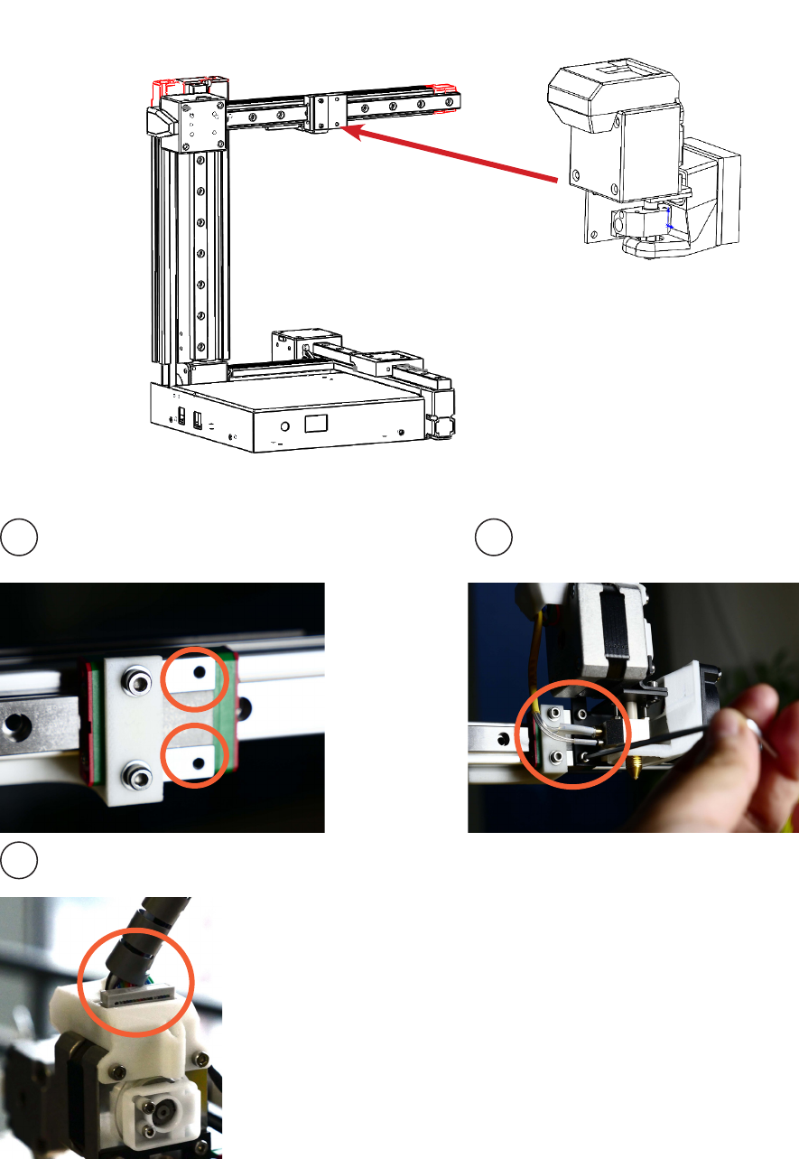
Installing the Print Head
1 2
3
Plug in print head
cable
8
Cetus3D
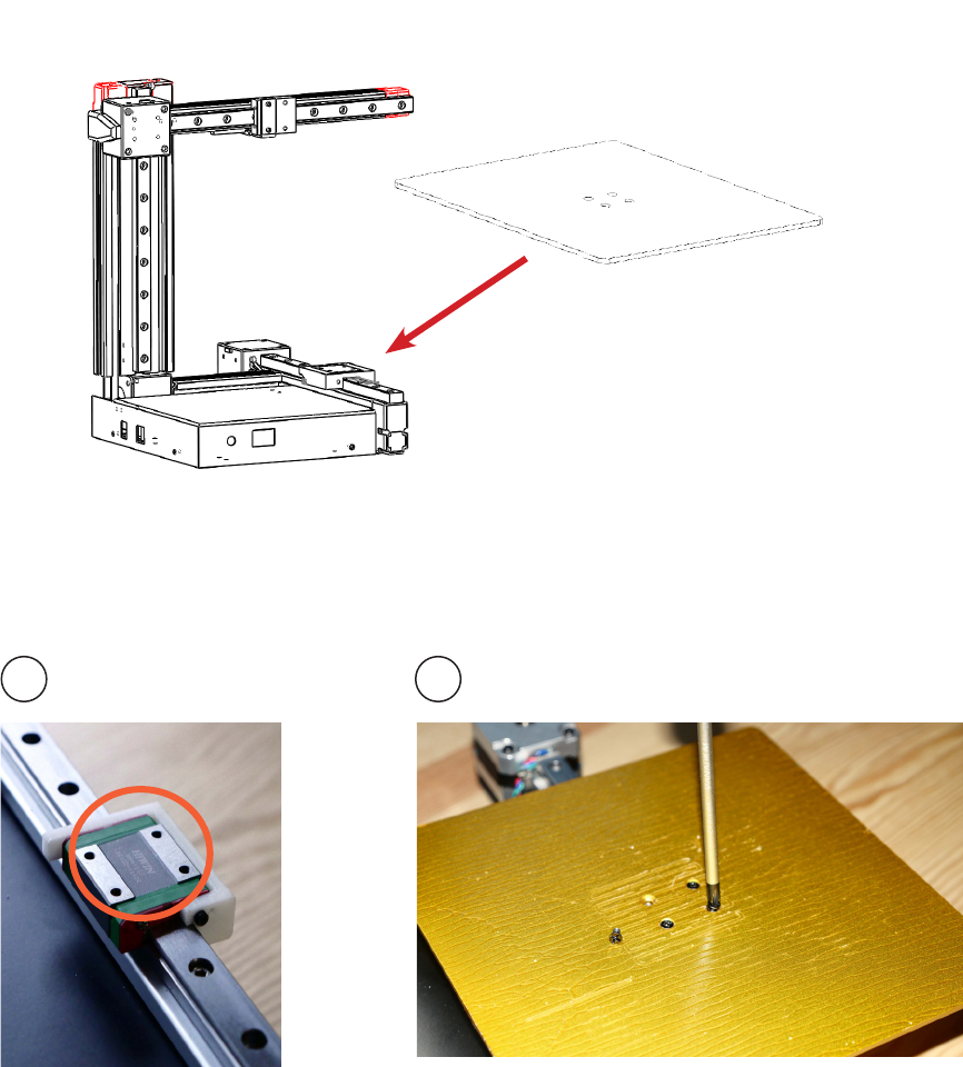
Installing the Build Platform
1 2
The machine is pre-leveled in factory.
There is no way and no need to level the build platform.
9
Cetus3D
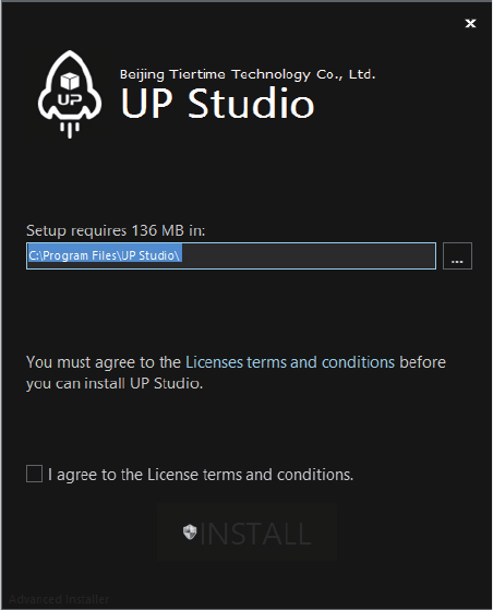
Install the Software
Cetus temporarily use the UP Studio as its printing software.
Please go to www.up3d.com to download the latest version. Mac users could go to Mac
App Store to download the latest version.
10
Cetus3D
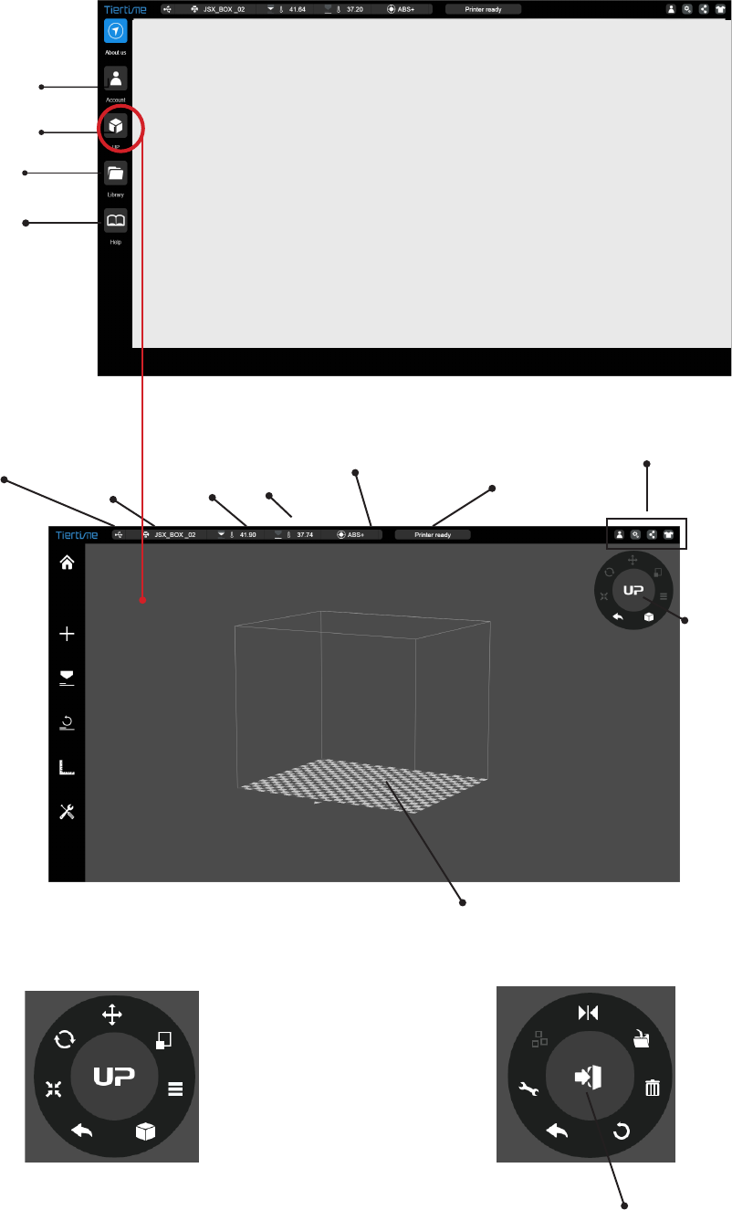
Software Interface
Account
UP (Print)
Library
Help
Printer name
Nozzle & Platform
Temperature
Current
Material
Printer Status
Account
Settings
Share
Skin
Model
Adjustment
wheel
Back to home
Add a Model/
Picture
Print
Initialize
Calibration
Maintenance
Connection
type
Build
Space
Mirror
Save
Delete
Restore to
default
Undo
Fix
Model
Perspectives
To 2nd Level
Menu
Undo
Scale
Move
Rotate
Auto Place
To 1st level
Menu
11
Cetus3D
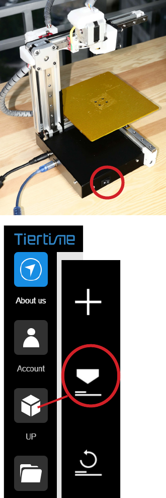
Starting Up the Printer
Initialization is required every time the
machine is switched on. During initialization,
the print head and the print platform move
slowly and hit the endstops of the XYZ
axes. This is essential as the printer needs
to nd the endpoints to each axis. Other
software options will light up and become
available for use only after initialization.
Initialize
Connect to power and computer as shown
in the photo on the right.
Turn on the machine using the power
switch.
Initialize the machine by clicking the
"Initialize" button in the software menu
12
Cetus3D
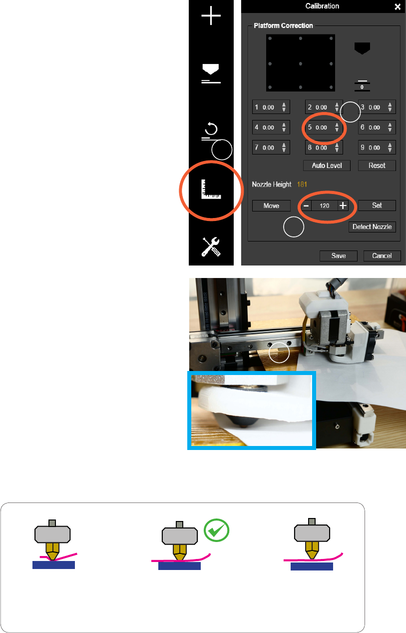
Setting the Nozzle Height
1. Go to Calibration.
2. Press button 5 to move print head to the middle
of the build platform.
3. Use the + button to lower the print head to close
proximity of platform.
4. Put a piece of paper in between the nozzle and
the platform.
5. Use the + and - buttons to adjust the print head
to just touching the paper.
6. Move the paper back and forth to feel the drag
between the nozzle and the platform. There should
be a slight resistance but the paper could be moved
freely. Refer to the figure at the bottom of this page.
7. When the correct distance is obtained, note
the value of current print head position, deduct
0.5mm from the value, and click the "Set"
button to set it as the Nozzle Height.
For example: If the print head position
determined by the paper is 179. Then set the
nozzle height to 178.5
1
2
3
4
The print head is too low. The
nozzle is pinning the paper
onto the platform. Lower the
platform slightly.
The height is just right.
Can feel some resistance
when moving paper.
The print head is too
high. No resistance is felt
at all when moving the
paper. Raise the platform
slightly.
13
Cetus3D
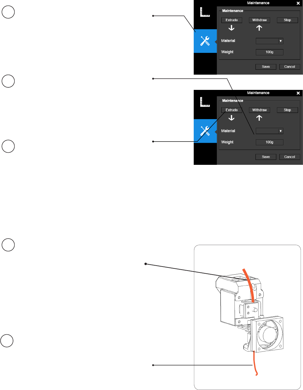
Preparing for Printing
Make sure the printer switched on
and connected to a computer. Click
the "Maintenance" button in the
software.
Choose PLA or the material
you choose from the dropdown
material list, and input the lament
weight.
Click "Extrude". The print head
will start to heat up. About ve
minutes, the temperature of the
print head will reach the melting
temperature, e.g. for PLA, it is
210°C. The printer will buzz and
the print head will start to extrude.
Gently insert the lament into the
small hole on the print head. The
lament will be fed into the print
head automatically when it reaches
the extruder gear inside the print
head.
Check the nozzle for plastic
extrusion. If plastic is coming out
from the nozzle, it means the
lament is loaded correctly and the
printer is ready for printing. (The
extrusion will stop automatically
after a while.)
1
2
3
4
5
PLA
PLA
Although ABS and ABS+ are
both available in the material list,
Cetus currently does not support
these materials.
14
Cetus3D
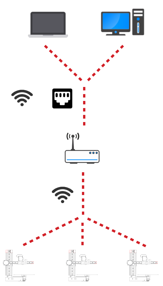
or
Connecting to Cetus through Wi-Fi requires a Wireless Local Area Network (WLAN). The
computer and the printers must connect to the same WLAN (same SSID) before they can
communicate.
In order to achieve stable Wi-Fi connection, It is highly recommended to use the printer under
a capacious Wi-Fi environment. A crowded network or an area with many Wi-Fi networks are
known to cause interruption during data transfer.
Setting Up Wi-Fi
15
Cetus3D
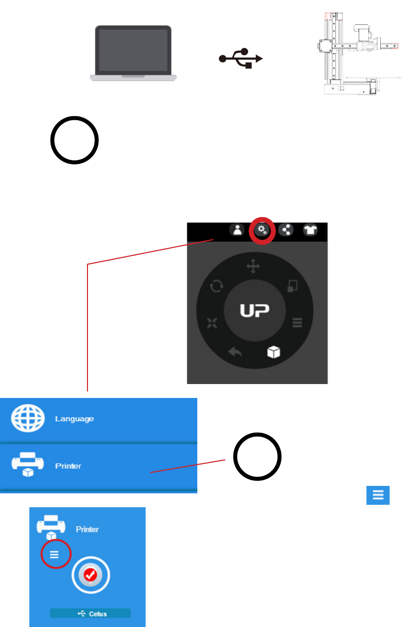
At the top right corner click the
printer tab
Click the “Printer Detail” button.
Wi-Fi Setup
Connect Cetus to a computer through USB.
2
1
16
Cetus3D
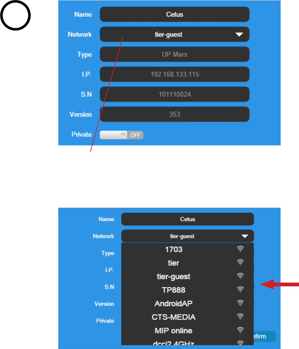
Click the dropdown menu to choose an available network.
3
Choose your network from the drop down list.
17
Cetus3D
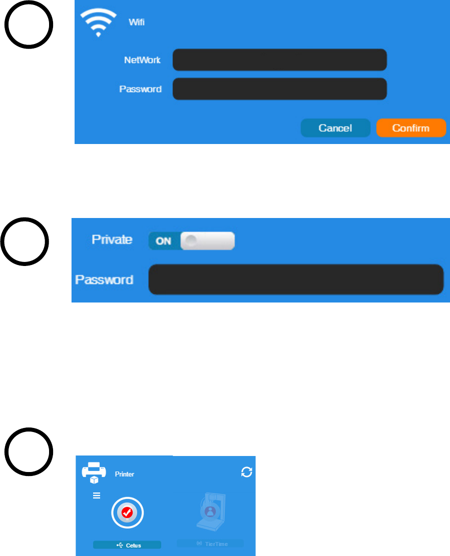
Disconnect USB and by clicking the available printer on the network to
operate through Wi-Fi.
Printer Tab
If “Private” is set to ON, a private password can be optionally added to limit
the printer access via Wi-Fi to trusted users. Please note that the password
for private access is a weak protection that anyone who can connect the
printer through USB connection can disable or change the password
without any limitation.
Input the password for the Wi-Fi network.
4
5
6
tier
18
Cetus3D
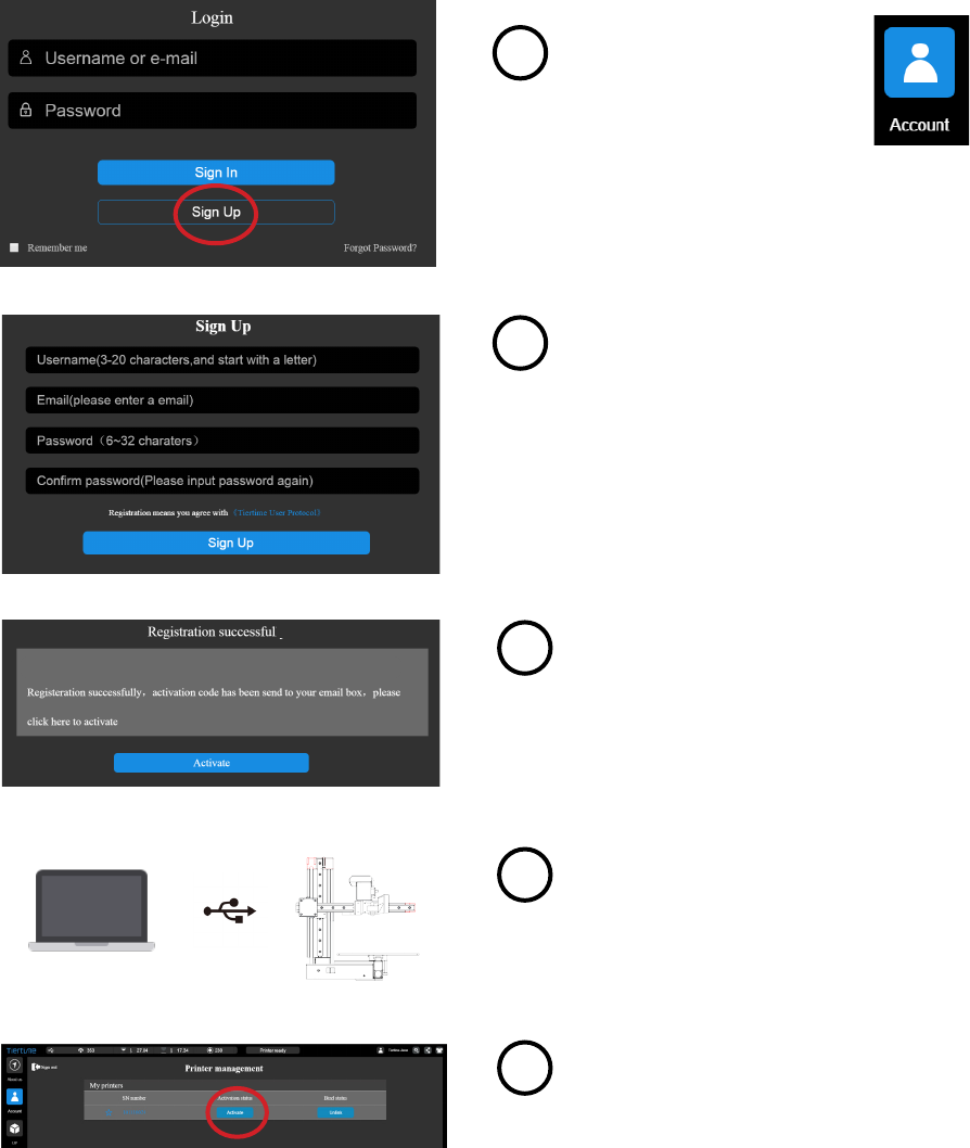
Product Activation
2
Press the "Account" button
at the main menu
Click the "Sign UP" button.
Register an UP account. If a user account is
already available, skip to step 5.
When nished the registration, go the
registered mail box, activate the account
through the activation email.
Connect the printer to a computer.
Go to the account section and Sign In. User
will see a printer management list. Find your
printer in the list, and click the “Activate”
button to activate your printer.
1
3
4
5
It is highly recommended to activate Cetus as soon as possible to be able to access its
unlimited printing power and the cloud based web functionality. The inactivated machine has
limited printing times before the activation is done.
Congratulations!
19
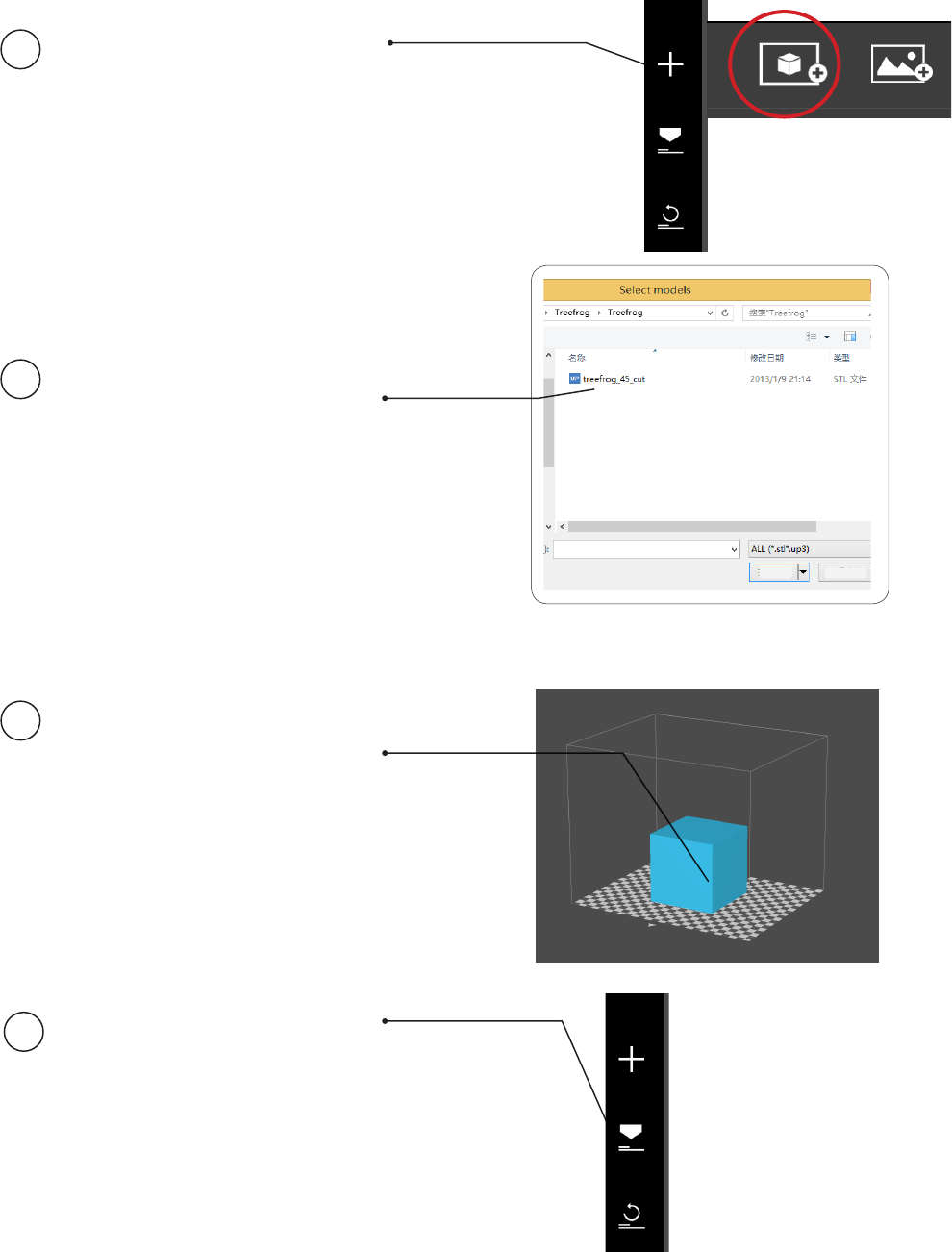
Cetus3D
Click "Import Mode
or Image", choose to
open a 3D model.
Choose your model.
The loaded model will
appear on the print plate.
Click "Print" to open the
print preview window.
Loading a Model
1
2
3
4
Open Cancel
20
Cetus3D
After sending the data, the program will
show the amount of material and the
time needed for the print job in a pop-
up window. At the same time, the nozzle
will start to heat up. The print will start
automatically.
Now your are safe to disconnect the
printer from computer.
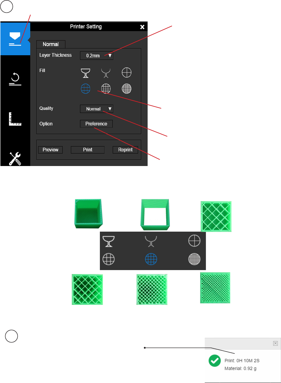
5
6
Set Layer Thickness
Select Inll Type
Select Print Quality/Speed
Shell: No inll,
normal wall.
Printing a Model
Make sure the printer is connected to a computer throug USB or Wi-Fi ( go to page 19
for details about Wi-Fi setting), and loaded a model.
Advanced Options
Surface: No top and bottom layers,
no inll, single perimeter.
Hollow
Big Hole
Loose Inll
Solid Inll
Click the print button to open the print interface
Please note that 0.05mm
and 0.07mm layers are
optimized for 0.2mm
diameter nozzles, while
0.6mm nozzle is only for
printing layer thickness of
0.3mm or above
21
Cetus3D
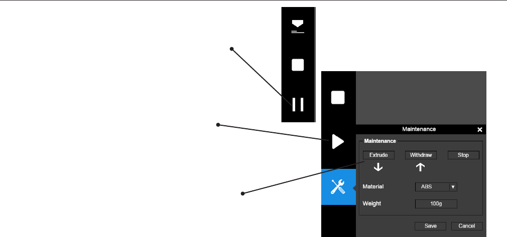
Pausing a Print Job
An on-going print job can be paused by clicking
the "Pause" button on the left hand side menu.
Click the "Resume Print" to resume the paused
print job. Once the print job is paused, the other
buttons on the maintenance interface will be
enabled.
You can change lament using the "Withdraw"
and "Extrude" buttons. At this point user could
even change materials.
22
Cetus3D
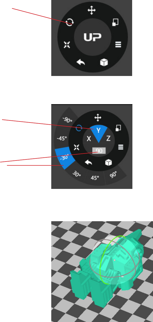
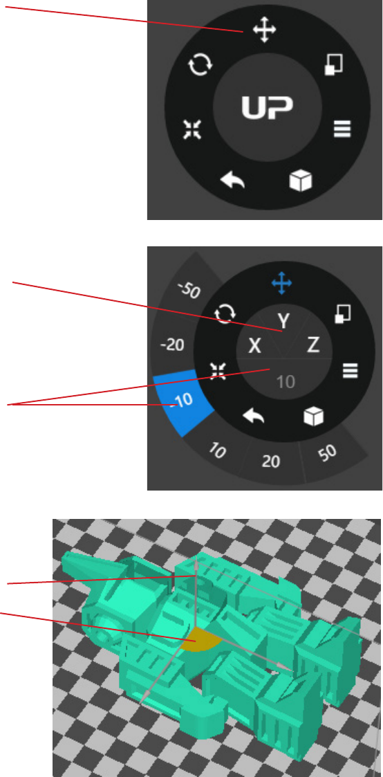
Rotating a Model
Choose the model and click
the rotate button.
Choose the rotation axis
Alternatively, user may use the
rotation guide to rotate the
model in real time by click and
drag using mouse.
User could input a specic
value or choose a preset value
for rotation.
23
Cetus3D
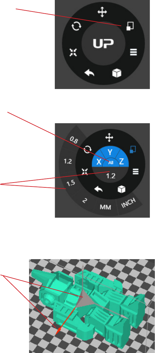
Scaling a Model
Choose the model and click
scale button.
By default the scaling is in all
axes. User could also choose a
specic axis for scaling.
User may input a specic
scaling factor or choose a preset
value.
Click MM or INCH to convert
the models to the size of
corresponding units.
Alternatively, user may use the
scaling guide on the model.
User could scale in a specic
axis or scale in all directions by
click and drag using mouse.
24
Cetus3D
Choose the model and click the
Move button.
Choose the direction of
movement.
User may input a specic value
or choose a preset value for the
distance of movement.
Alternatively, user may use the
translational guide on the model
to move on the X-Y plane or a
single direction by click and drag
using mouse.
Move a Model
25
Cetus3D
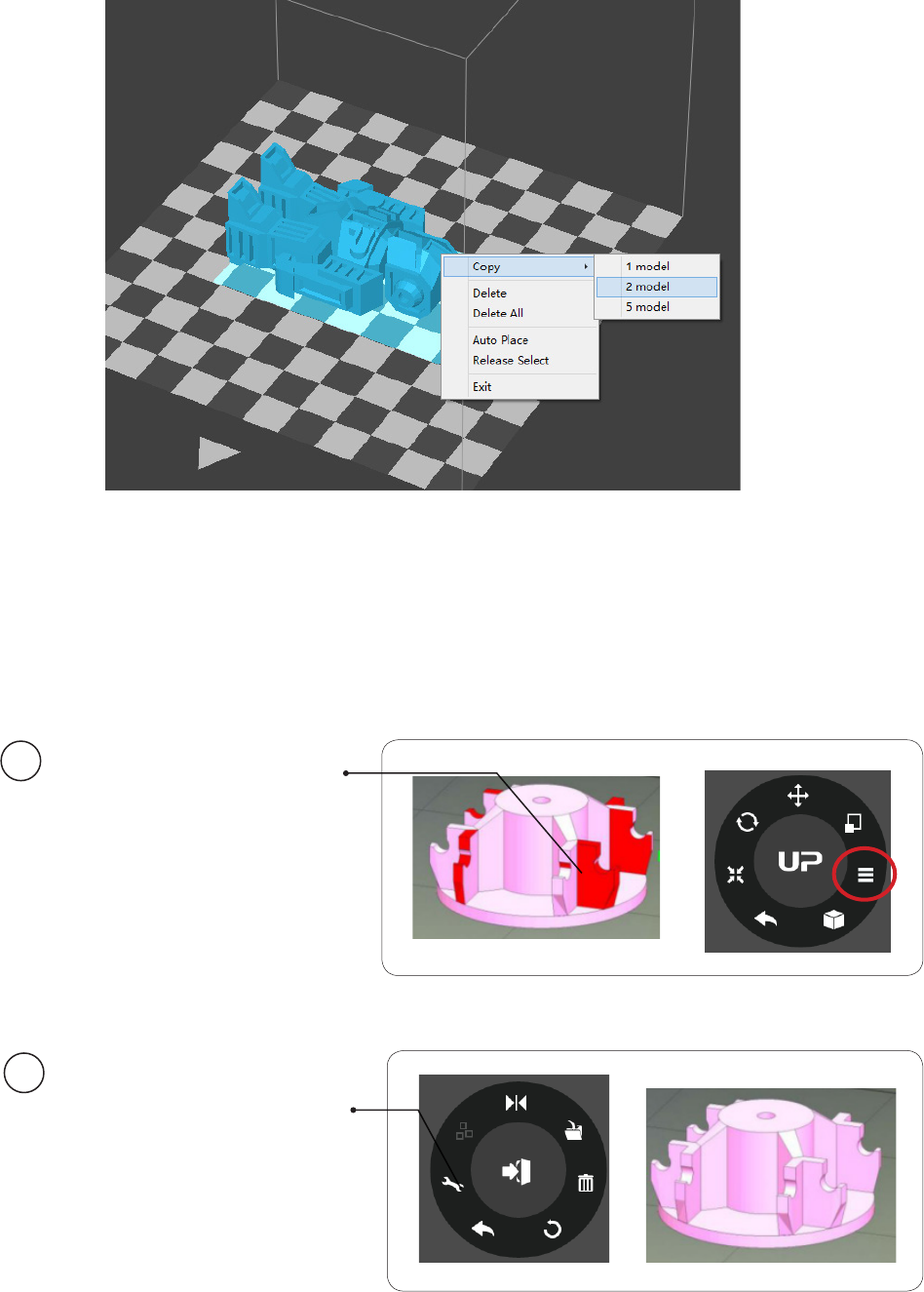
Making Copies
Choose the model by clicking it (hight lighted), then right-click to
bring up the menu and select the number of copies.
Repairing a Model
If the model contains
defective surfaces, the
software will highlight the
defective surfaces in red.
Click the "More" button
to reach the second level
menu.
Click the "Fix" button to
repair the model.
The red defective surfaces
will be changed to the
normal color if the defects
can be repaired.
1
2
26
Cetus3D
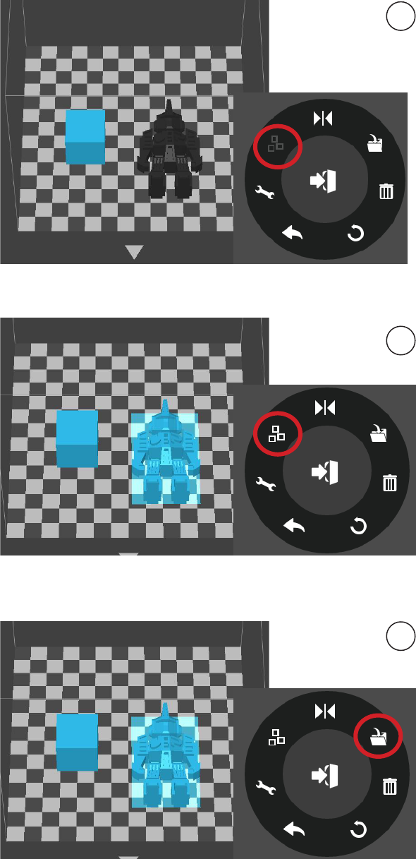
Merging and Saving Models
Ctrl/CMD-click all the models on the
build plate.
The Merge button on the second
level of the adjustment wheel will
become available. Click the "Merge"
button to merge the models.
1
2
Click the "Save" button to save the
merged models to the comptuer.
3
If models place too closed together, their raft could overlap whcih could hinder extrusion.
Merging convert all selected models into one single model, thus it raft would be calculated
as a single models without overlapping. Merging could be a convenient option if user want to
preserve the relative postions of a set of models.
27
Cetus3D
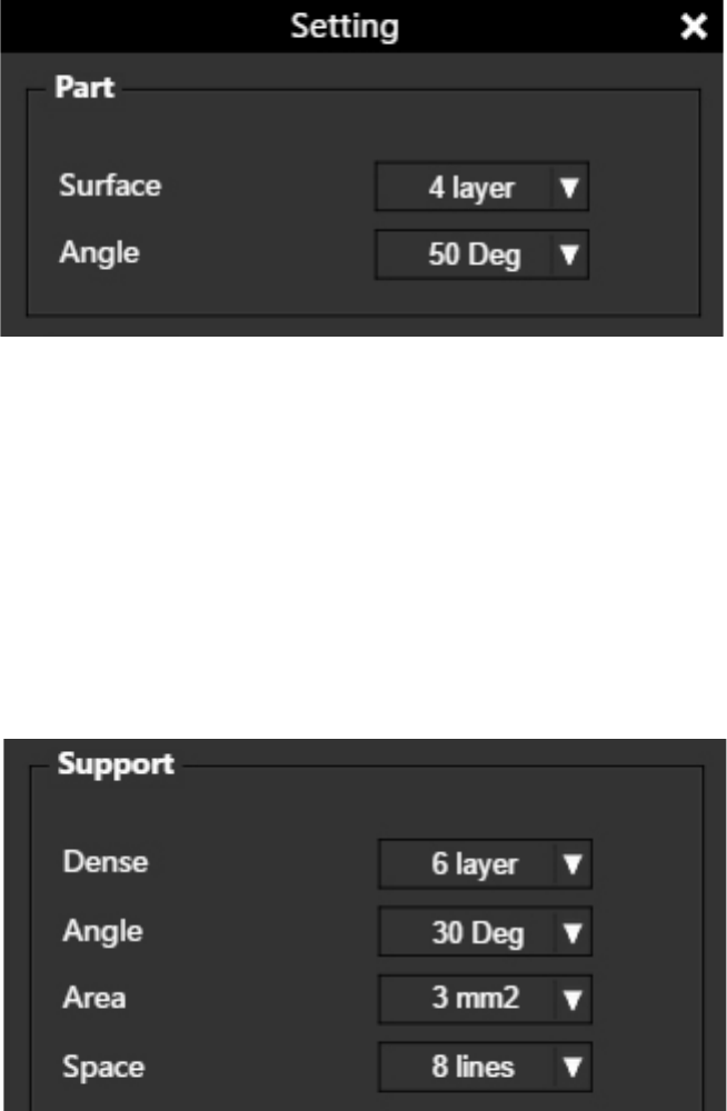
Surface: The number of layers that sealing the top and the bottom of the printed
object.
Angle: This value determines at which angle the Surface layers start to be printed.
Dense: Choose the number of the dense layers between the support structure
and the supported surfaces.
Angle: Determine the angle at which the support structure and the dense layers
to be generated.
Area: Determine the minimal area of a surface that a support structure will
be generated. The area smaller than this value will have no support structure
generated.
Space: Determine how dense the support structure will be. The larger the value,
the less dense the support.
Print Preference
28
Cetus3D
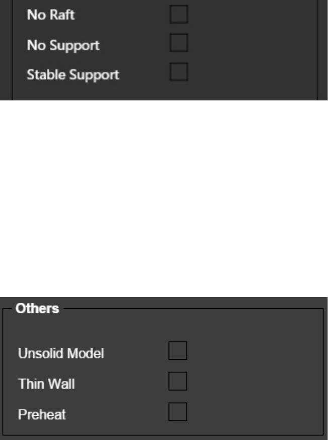
No Raft: Print without raft.
No Support: Print without support.
Stable Support: Support structure will be stronger but harder to be
removed.
Unsolid Model: The software will autox nonsolid models.
Thin Wall: The software will detect the wall thickness that is too thin to print
and expand the wall to a printable size.
Preheat: Preheat the build plate for maximum 15 minutes before printing
starts.
Print Preference
29
Cetus3D
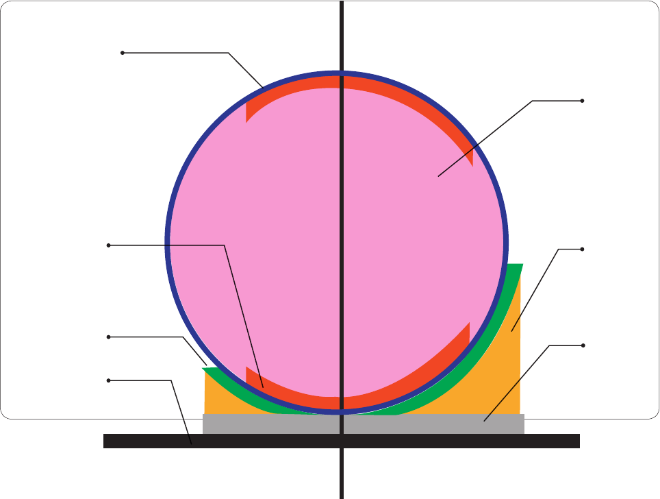
Printing Parameters
Dense: Solid support structure ensures that the surface being supported retains its shape and
surface nish.
Inll: The inner structure of the printed object. The density of the inll can be adjusted.
Raft: The thick structure that assists with the adhesion of the object to the platform.
Surface: The top and the bottom layers of the printed object.
Surface
Dense
(support)
Surface
Print
Platform
Inll
Support
Raft
<30o <90o
30
Cetus3D
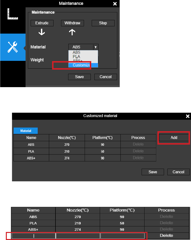
Using Customized Material Prole
It is possible to use customized
material prole to control the
printing temperature and platform
temperature. This function is
very useful for using third party
materials that cannot print well
using the preset proles.
The use the customized prole,
go Maintenance and choose
"Customize" in the material list.
Click "Add" to add customized prole.
Input prole name, nozzle temperature and platform temperature.
31
Cetus3D
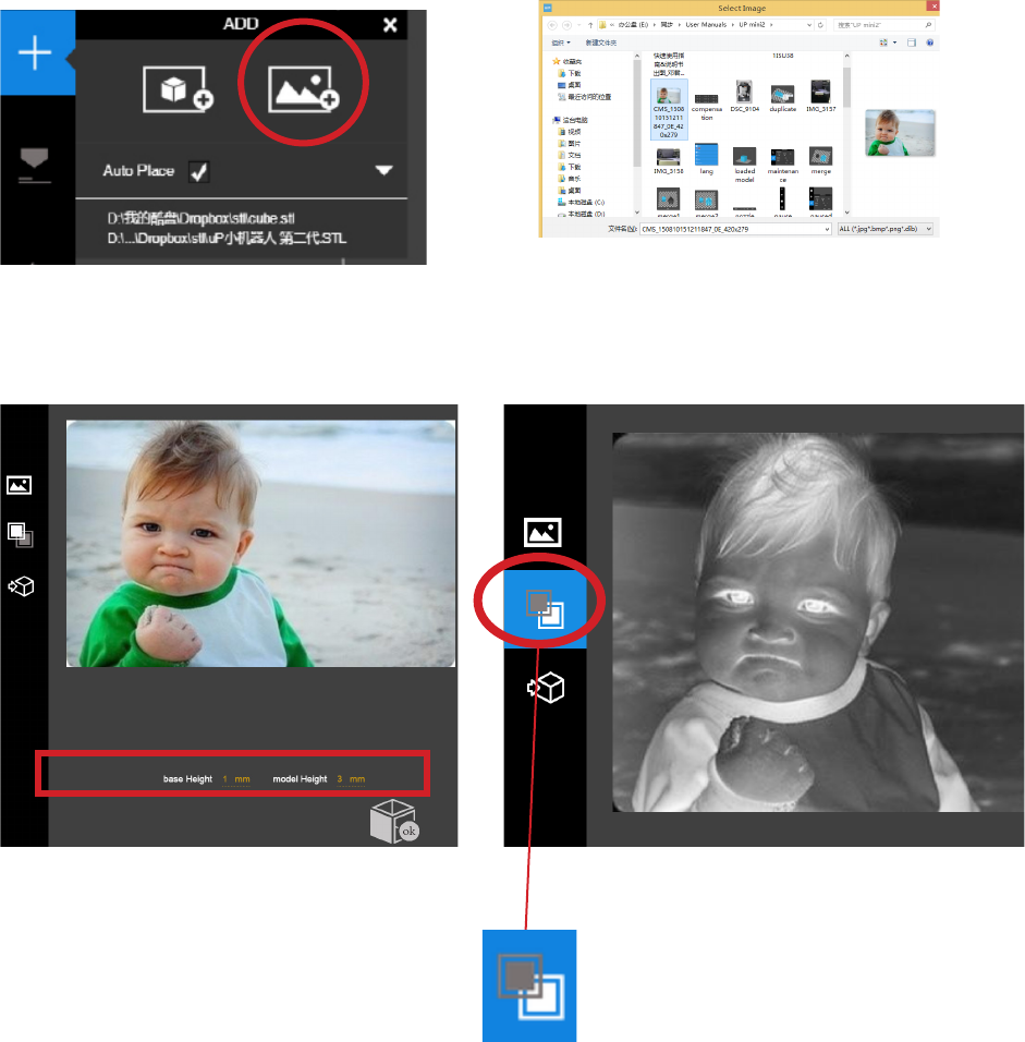
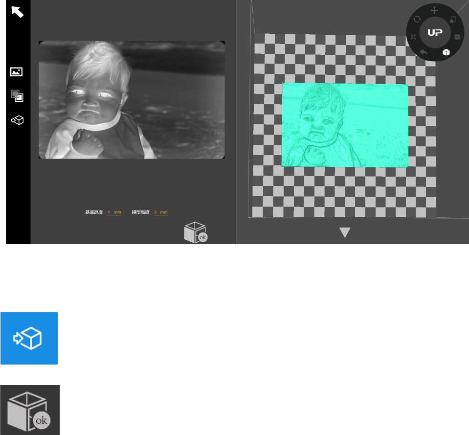
Converting a 2D Picture Into a 3D Model
Click the “Add Picture” button and select a picture.
The "Convert Negative" button
will reverse the pixel intensity
so that user could choose the
picture to be protruding from or
sunken into the base.
Base Height determines the thickness
of a at layer that holds the picture.
Model Height determines the contrast
of the nal print.
32
Cetus3D
Update 3D model button. This button will convert the modied picture
on the left to a 3D rendering on the right.
OK button sends the 3D rendering to the 3D printing interface for
printing.
Converting a 2D Picture Into a 3D Model
33
Cetus3D
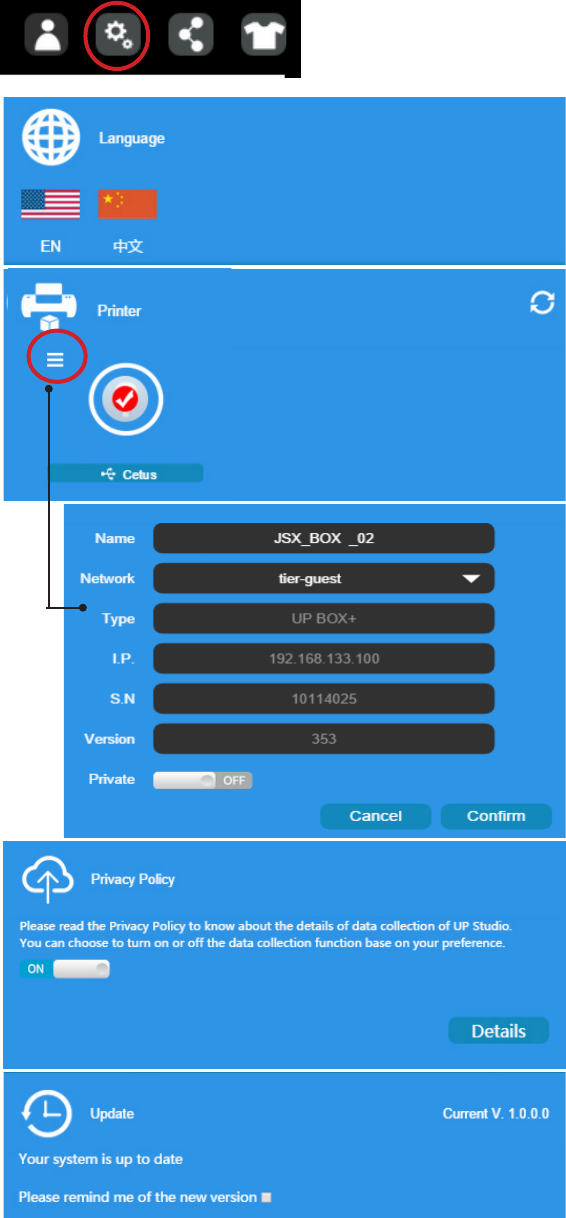
Machine and Software Settings
Click the "Setting" button to bring up the
menu
Choose a Language
Choose and Set the Printer's
Name
Printer Name and
Wi-Fi Settings
Privacy Setting
Auto Update Setting
34
Cetus3D
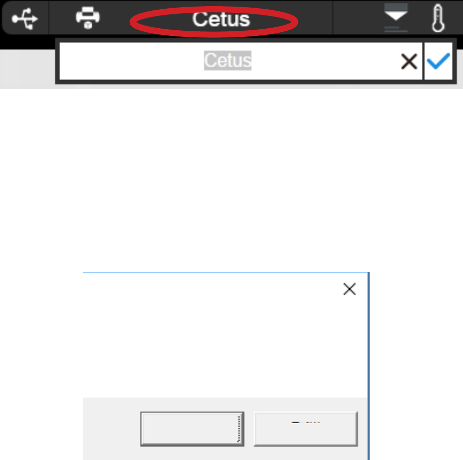
User could rename the printer by clicking the printer name on the status bar.
Printer Info and Naming a Printer
Blackout Recovery
A print job could be resumed after an electricity cutoff. The next time when the printer
connects to a computer and after an initialization, a pop up window will appear to let the user
choose to resume the interrupted print job.
Print job stopped at XXX layer,
continue?
OK Cancel
35
Cetus3D
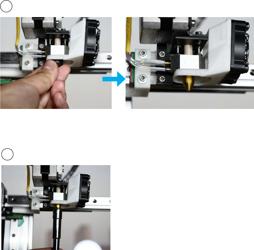
Change nozzle
1
2
While the machien is cold, remove
the peek cap by hand. If cannot
remove by hand, use a plier.
Use the nozzle wrench provided to remove
the nozzle.
When install the new nozzle, just reverse
the previous steps. Install the nozzle using
the wrench, then put on the peek cap by
hand, do not screw the cap too tight.
Please note that 0.05mm and 0.07mm layers are optimized for 0.2mm
diameter nozzles, while 0.6mm nozzle is only for printing layer
thickness of 0.3mm or above
This device complies with Part 15 of the FCC Rules. Operation is subject to the following two
conditions: (1) this device may not cause harmful interference, and (2) this device must accept any
interference received, including interference that may cause undesired operation.
Changes or modifications not expressly approved by the party responsible for compliance could
void the user's authority to operate the equipment.
NOTE: This equipment has been tested and found to comply with the limits for a Class B digital
device, pursuant to Part 15 of the FCC Rules. These limits are designed to provide reasonable
protection against harmful interference in a residential installation. This equipment generates, uses
instructions, may cause harmful interference to radio communications. However, there is no
guarantee that interference will not occur in a particular installation. If this equipment does cause
harmful interference to radio or television reception, which can be determined by turning the
equipment off and on, the user is encouraged to try to correct the interference by one or more of
the following measures:
-- Reorient or relocate the receiving antenna.
-- Increase the separation between the equipment and receiver.
-- Connect the equipment into an outlet on a circuit different from that to which the receiver is
connected.
-- Consult the dealer or an experienced radio/TV technician for help.
The distance between user and products should be no less than 20cm