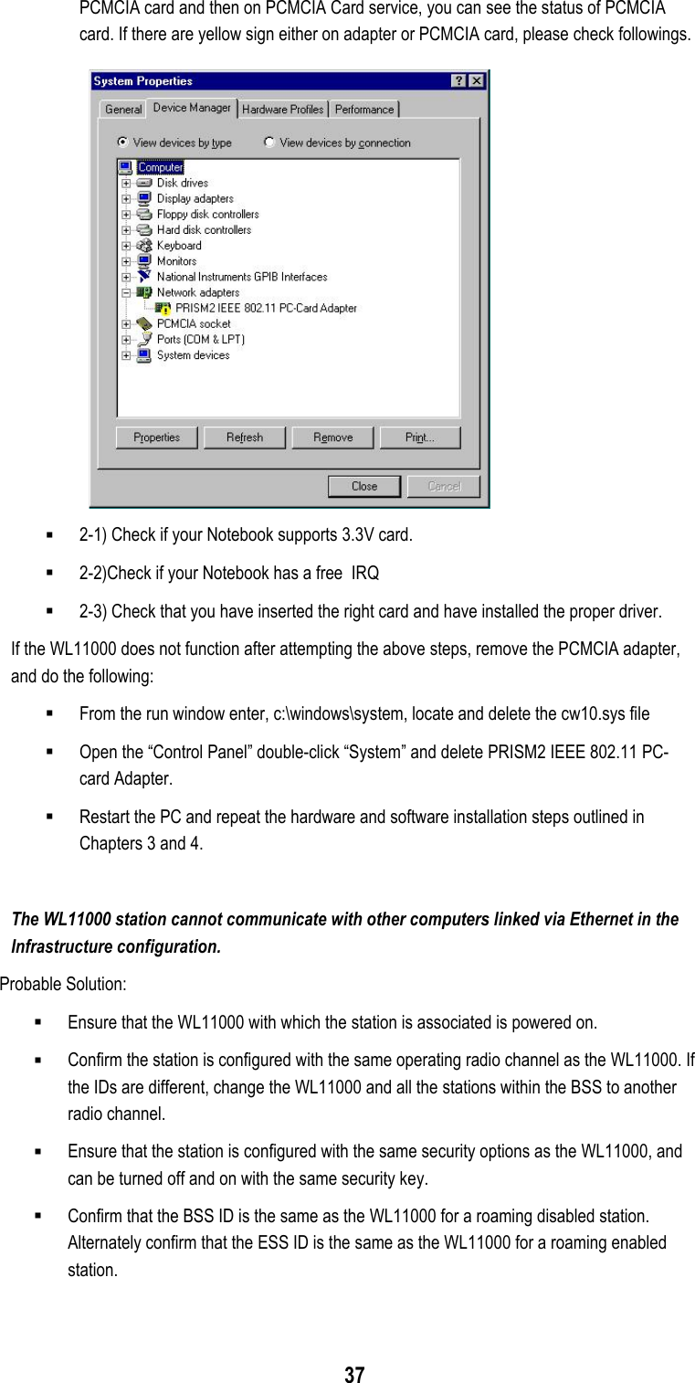
Belkin F5D6020 Wireless Network Card User Manual WL11000

Belkin International, Inc. Wireless Network Card WL11000

Revised Manual

WWLL1111000000Wireless LAN PCMCIA AdapterUSER MANUALVersion 0.9.2, February 16, 2000
2Federal Communications Commission StatementThis device complies with FCC Rules Part 15.  Operation is subject to the following two conditions:This device may not cause harmful interference.This device must accept any interference received, including interference that may cause undesiredoperation.This equipment has been tested and found to comply with the limits for a Class B digital device,pursuant to Part 15 of the FCC Rules.  These limits are designed to provide reasonable protectionagainst harmful interference in a residential installation.  This equipment generates, uses and canradiate radio frequency energy.  If this equipment is not installed and used in accordance with themanufacturer's instructions, it may cause harmful interference to radio communications.  However,there is no guarantee that interference will not occur in a particular installation.  If this equipmentdoes cause harmful interference to radio or television reception, which can be determined by duringthe equipment off and on, the user is encouraged to try to correct the interference by one or moreof the following measures: Reorient or relocate the receiving antenna. Increase the separation between the equipment and receiver. Connect the equipment to an outlet on a circuit different from that to which the receiver isconnected. Consult the dealer or an experienced radio/TV technician for help.The use of shielded cables for connection of the monitor to the graphics card is required to assurecompliance with FCC regulations.  Changes or modifications to this unit not expressly approved bythe party responsible for compliance could void the user's authority to operate this equipment.Manufacturer's Disclaimer StatementThe information in this document is subject to change without notice and does not represent acommitment on the part of the vendor.  No warranty or representation, either expressed or implied,is made with respect to the quality, accuracy or fitness for any particular purpose of this document.The manufacturer reserves the right to make changes to the content of this document and/or theproducts associated with it at any time without obligation to notify any person or organization ofsuch changes.  In no event will the manufacturer be liable for direct, indirect, special, incidental orconsequential damages arising out of the use or inability to use this product or documentation,even if advised of the possibility of such damages.  This document contains materials protected bycopyright.  All rights are reserved.  No part of this manual may be reproduced or transmitted in anyform, by any means or for any purpose without expressed written consent of its authors.  Productnames appearing in this document are mentioned for identification purchases only.  All trademarks,product names or brand names appearing in this document are registered property of theirrespective owners.FCC RF Radiation Exposure Statement:This equipment complies with FCC RF radiation exposure limits set forth for anuncontrolled environment. This equipment should be installed and operated with aminimum distance of 20 centimeters between the radiator and your body.This transmitter must not be co-located or operating in conjunction with any otherantenna or transmitter.
3ContentsChapter 1 About the WL11000 PCMCIA Card........................................................... 41-1 Features .............................................................................................................................................. 41-2 Applications ......................................................................................................................................... 41-3 Product Kit ........................................................................................................................................... 5Chapter 2 Network Configuration and Planning ...................................................... 62-1 Network Topology................................................................................................................................ 62-2 Roaming .............................................................................................................................................. 8Chapter 3 Adapter Installation and Configuration – Windows® 98 ......................... 93-1 System Requirements ......................................................................................................................... 93-2 Inserting the Adapter ........................................................................................................................... 93-3 WL11000 Driver Installation -Windows® 98 ....................................................................................... 103-4 Adapter Configuration – Windows® 98............................................................................................... 133-5 Protocol Installation – Windows® 98 .................................................................................................. 193-6 WL11000 Setup for Windows NT 4.0 ................................................................................................ 24Chapter 4 Installing and Navigating the PRISM Configuration Utility .................. 284-1 PRISM Configuration Utility - Installation........................................................................................... 284-2 PRISM Configuration Utility- Navigation............................................................................................ 31Appendix A Troubleshooting................................................................................... 36Appendix B Glossary................................................................................................ 38
4Chapter 1 About the WL11000 PCMCIA CardThe WL11000 IEEE 802.11 PCMCIA PC Card is compatible with any standard, notebook computerType II or Type III PCMCIA slot. As a Plug-and-Play device, Windows 95/98 will automaticallyrecognize the WL11000 PCMCIA card and initiate the installation process. Upon successfulinstallation, the WL11000 PCMCIA card will communicate seamlessly with other WL11000 wirelesshome and office networking products.1-1 FEATURES1. Supports up to 11 Mbps data rate: T-1 line alternative/replacement that dramatically cutscosts.2. Working range up to 800 ft. in an open environment enhances mobility.3. Supports point-to-point and point-to-multipoint access provides increased flexibility.4. Seamless connectivity to wired Ethernet and PC network LAN’s offers quick, trouble-freeintegration with existing networks.5. Robust Direct Sequence Spread Spectrum (DSSS) technology provides secure,interference-resistant wireless connection.6. Wireless connections eliminate the hassle and cost of cabling.7. Supports a wide range of LAN (Local Area Network) Network Operating Systems (NOS)including Windows ® 98 and  Windows  NT™8. Easy Plug and Play installation9. Omni - directional antenna included10. Greater flexibility to locate or move networked PC’s1-2 APPLICATIONSWL11000 products offer a fast, reliable, cost-effective solution for wireless client access to thenetwork the following applications and environments: Remote access to corporate network information E-mail, file transfer and terminal emulation Difficult-to-wire environments Historic or older buildings Buildings with asbestos insulation Open areas where wiring is difficult to employ Frequently changing environments Retailers, manufacturers or other organizations that frequently rearrange the workplaceor relocate Temporary LANs for special projects or peak time usage
5 Trade shows, exhibitions and construction sites that employ temporary networks.Retailers, airline and shipping companies that need additional workstations for a peakperiod and Auditors that require workgroups at customer sites. Access to database for mobile workers Medical, Technical and Retail specialists that require roaming access to a database orother network resources. SOHO (Small Office and Home Office) users Perfect for users that need a small, easy-to-install network that deploys rapidly. Inter-building connection Wireless building-to-building networks are quickly and easily installed, require no monthlylease fees, and provide the flexibility to reconfigure easily.1-3 PRODUCT KITThe WL11000 product kit includes the following items. Ensure that the items in the following listhave been included. If any of the listed items are missing, please contact your local dealer. 1 X WL11000 PCMCIA Type II Adapter 1 X Driver 1 X User Manual & Utility CD pack
6Chapter 2 Network Configuration and PlanningThe WL11000 supports legacy Ethernet LAN network configuration options as defined by the IEEE802 standards committee.The WL11000 can be configured as: Ad-Hoc for departmental or SOHO LANs Infrastructure for enterprise LANs LAN-Interconnection for point-to-point link as a campus backbone2-1 NETWORK TOPOLOGYFig. 1 - Ad-Hoc Wireless LANAn Ad-Hoc wireless LAN is a group of computers, each equipped with one WL11000 adapter,connected as an independent wireless LAN. Computers in a specific Ad-Hoc wireless LAN must beconfigured to share the same radio channel.Ad-Hoc wireless LAN configurations are appropriate for branch level departments or SOHOoperations.Ad-Hoc WirelessLAN
7Fig. 2 - Infrastructure Wireless LAN ConfigurationThe WL11000 provides access to a wired LAN for wireless workstations. An integrated wirelessand wired LAN is called an Infrastructure configuration. A group of WL11000 PC users and anAccess Point compose a Basic Service Set (BSS). Each WL11000 PC in a BSS can talk to anycomputer in the wired LAN infrastructure via the Access Point.An Infrastructure configuration extends the accessibility of a WL11000 equipped PC to a wired LAN,and doubles the effective wireless transmission range for 2 WL11000 PCs. Since the Access Pointis able to forward data within its BSS, the effective transmission range in an infrastructure LAN isdoubled.Fig. 3 - The effective Transmission Range   
8The use of a unique ID in a BSS is essential. All WL11000 equipped PCs configured withoutroaming options in an independent BSS must be configured with a BSS ID corresponding to theWL11000SA used in the BSS. Check your WL11000SA for its BSS ID or use the Access PointBrowser Utility program to determine the BSS ID.The Infrastructure Wireless LAN configuration is appropriate for enterprise-scale wireless access toa central database, or as a wireless application for mobile users.A point-to-point LAN configuration is possible when two access points are linked with an optionaldirectional antenna (the directional antenna is an optional accessory, please contact your dealer forinformation). The optional directional antenna makes LAN-Interconnection to a wireless backbonebetween buildings possible.2-2 ROAMINGInfrastructure mode also supports roaming capabilities for mobile users. More than one BSS can beconfigured as an Extended Service Set (ESS). The continuous network allows users to roam freelywithin an ESS. All WL11000 PCs and WL11000SAs within one ESS must be configured with thesame ESS ID and use the same radio channel.Fig. 4 - Roaming in an Extended Service Set (ESS)Before enabling an ESS with roaming capability, choosing a feasible radio channel and optimumAccess Point position is recommended. Proper Access Point positioning combined with a clearradio signal will greatly enhance performance. 
9Chapter 3 Adapter Installation and Configuration – Windows® 983-1 SYSTEM REQUIREMENTSIn order to install and use the WL11000 PCMCIA card your PC system must meet the followingrequirements: A PCMCIA Type II or Type III slot PCMCIA revision 2.10 compliant card and socket services Windows® 98 (with the Windows® CD, for use during installation) 500 Kbytes free disk space for utility and driver installation3-2 INSERTING THE ADAPTERTo insert the WL11000 Network Adapter into a notebook computer, do the following:1. Locate an available Type II or Type III PCMCIA slot.2. With the PCMCIA adapter’s 68-pin connector facing the PCMCIA slot and the“WL11000PCMCIA” label facing up slide the PCMCIA adapter completely into thePCMCIA slot.Fig. 5 Insert the WL11000 into NotebookAfter properly inserting the Network Adapter into your notebook, continue with the WL11000 driverand PRISM  Configuration Utility installation.NOTE: The PCMCIA slot allows “hot swap” of PCMCIA adapter. You may insert or remove theWL11000 / PCMCIA adapter from the slot anytime, even when the power of your computer is on.NOTE: Windows® 98 requires that the Network card and socket services must be compliant withthe PCMCIA revision 2.10 specification. Please check the documentation of the PCMCIA driverbefore installing the WL11000 PCMCIA adapter.
103-3 WL11000 DRIVER INSTALLATION -WINDOWS® 98Note: Before proceeding, have the Windows® 98 CD ready, as it will be required during thesoftware installation process.1. Insert the WL11000 A adapter into a standard Type II or Type III PCMCIA card slot, asdescribed in the preceding section.2. Windows® 98 will automatically detect the WL11000 and prompt you to install thenecessary driver. Click “Next” to begin the installation.3. Check “Search for the best driver…” click “Next”.
114. Check “Floppy-disk drives” click “Browse”. Double-click the “Setup” folder icon from thelist, double-click the setup.exe icon. Windows® will automatically enter the path click“Next”.5. Windows® will then acknowledge that it has found the appropriate driver, click "Next"Windows® will now install the driverAs the driver files are being copied to the appropriate location, you will be prompted toinsert the Windows® 98 CD.
126. Insert the Windows® 98 CD. Select “D:\win98” from the drop down list (where “D”represents the CD-ROM drive), click “OK”NOTE: You must insert the Windows 98®CD as the driver installation requires special files thatwill not be available even if you have stored a copy of Windows® 98 on your hard drive.7. After Windows® has finished installing the appropriate files click “Finish”8. You will be prompted to restart your computer, click "YES" to complete the installation.
133-4 ADAPTER CONFIGURATION – WINDOWS® 98After successful installation of the WL11000 and its driver, continue the installation process byconfiguring the WL11000 adapter properties. To configure the WL11000 Adapter complete thefollowing steps :1. From the Control Panel, double-click the “Network” icon2. Select "PRISM2IEEE 802.11 PC Card Adapter" from the list and press the “Properties”button.
143. From the “Properties” menu select the “Advanced” tab.4. Select “Channel” from the list, and choose a “Value” from the drop down list. FCCregulations require a “Value” between 1 and 11.
155. Select “Network Type”, and choose “Infrastructure” or  “Ad-Hoc” as the “Value”.Note: “Infrastructure” mode allows a wireless adapter to communicate with a wired network,while “Ad-Hoc” mode allows wireless-to-wireless communication. Consult your SystemAdministrator for information about your network communication type. For more informationabout Infrastructure and Ad-Hoc networks, see Chapter 2 of this manual6. Select “Power Save Mode” and choose a “Value”.NOTE: To allow uninterrupted data communication, choose “Disabled” as the “Value”.Choosing “Enabled” allows your notebook to enter “sleep” mode, however, this will interruptdata communication. Consult your System Administrator to find out the best setting for yournetwork type. For more information about Power Save Mode, see the chapter entitled “PRISMConfiguration Utility” in this manual.
167. Select “Power Save Mode” and choose a “Value”.NOTE: To allow uninterrupted data communication, choose “Disabled” as the “Value”.Choosing “Enabled” allows your notebook to enter “sleep” mode, however, this will interruptdata communication. Consult your System Administrator to find out the best setting for yournetwork type. For more information about Power Save Mode, see the chapter entitled “PRISMConfiguration Utility” in this manual.8. Select “SSID”; enter a “Value” of “PRISM2”.NOTE: The SSID can have any value, but should have the same value as the Access Point(AP). In Ad-Hoc mode, all clients should share the same SSID.
179. Select “Transmit Rate”, and choose a “Value”.NOTE: Fixed 11 Mb/s is the preferred “Value” for environments where the client has line ofsight access and is a short distance away from the AP. Fully Auto is the recommended settingfor clients that are farther away from the AP and where there may be interference between theclient and the AP.10. Select “Use Wep”, and choose a “Value”.NOTE: Wired Equivalent Privacy (Wep) is an encryption scheme used to protect wireless datacommunication. Selecting “Disabled” will prevent you from sharing data with other computers ifyour network uses Wep. If your network is Wep enabled, you must choose “Mandatory”.Consult your System Administrator for more information about your network type. For moreinformation about Wep, see the chapter entitled “PRISM Configuration Utility” in this manual.
1811. After the configuring the “Properties”, click “OK” and continue with the ProtocolInstallation, described in the following section.
19 3-5 PROTOCOL INSTALLATION – WINDOWS® 98Before continuing with the Protocol installation consult your System Administrator for details aboutyour specific network. To install network protocols complete the following steps.1. From the “Control Panel” double-click the “Network” icon.2. Select “PRISM2 IEEE 902.11 PC Card Adapter” and click “Add”.3. Highlight “Protocol” and click “Add”
204. Select “Microsoft” from the list of “Manufacturers” and “TCP-IP” from the list of “NetworkProtocols”, click “OK”5. Select “TCP/IP “ and click “Properties”.Repeat step 2 – 5 to install other protocols such as NetBeui or IPX/SPX.NOTE: The following steps apply to DHCP servers. Consult your system administrator forspecific information regarding your server type, and for help in specifying an IP address if you donot use a DHCP server and must manually enter the IP address and DNS number.
216. Check “Obtain an IP address…” and click “OK”. If you are using a DHCP server the IPaddress will be entered automatically.7.  From the Network menu highlight “Client from Microsoft Networks”, and click" File andPrint Sharing”.
228. Check both boxes and click “OK”.9. Enter a “Computer name”, “Workgroup” and “Computer Description”, click “OK”
2310. Enter a “Computer name”, “Workgroup” and “Computer Description”, click “OK”11. You will be prompted to restart your computer, click “Yes” to complete the installation.Note: Please see the trouble shooting if you encounter some problem while installing the PC-Card card  or your PC-Card  is non-functional.
243-6 WL11000 SETUP FOR WINDOWS NT 4.0Login as Administrator1. From the desktop, select “Control Panel”, double-click “Network”, click “Adapters”, click“Add”2. Click “Have Disk”3. Insert the WL11000 disk; Windows NT will manually enter the path to the driver click “OK”.
254. Select your adapter from the list click “OK”.5. Click “Close” from the “Network” dialog, Windows NT will auto-bind the new adapter withany network protocols already installed on the system.
266. After the auto-binding procedure is complete, select “Properties” from the “Network”dialog. At this point you may choose to manually specify an IP address, or automaticallyobtain an IP address if you are using a DHCP server. Consult your Systems Administratorfor information about your server type, IP address settings and DNS number.7. After the settings configuration is complete, confirm that the “Computer Name” and“Workgroup” designations are correct, and click “OK”.
278. You will be prompted to restart your computer, click yes to complete the installation9. Upon restart, open the “Devices” menu from the “Control Panel”, to confirm that the driverinstallation was successful. Your adapters driver should now be listed in the “Devices”menu.
28Chapter 4 Installing & Navigating the PRISM Configuration Utility4-1 PRISM CONFIGURATION UTILITY - INSTALLATION1. Insert the PRISM Network Configuration Utility disk into an available floppy disk drive.From the "Run" window type "A:\WL1100\WLU\setup.exe" (where "A" represents a floppydisk drive).2. Click “Yes” to accept the License Agreement and continue with the installation.3. Click “Next”.
294. Enter the System ID click “Next”.5. Choose the Network Mode, click “Next”6. Browse to install the utility in another folder, or confirm the installation and click “Next”.
307. You will be prompted to insert Disk 2. Insert the disk and click “Browse”. Double-click the“Setup” folder; double-click again on the “setup” icon. When the path has beenautomatically entered in the “Setup Needs The Next Disk” dialog, click “OK”.8. After installation is complete, you will be prompted to restart your computer. Check “Yes”and click “Finish” to complete the installation and begin navigating the PRISMConfiguration Utility.
314-2 PRISM CONFIGURATION UTILITY- NAVIGATIONThe following section describes and defines the various functions of the PRISM NetworkConfiguration Utility. This utility provides quick access to all adapter settings.PRISM Quick-Launch Icon: After installation is complete, a PRISM utility icon will appear inthe “Quick-Launch” menu in the lower right hand corner of the screen, near the clock.The PRISM Configuration Utility: Double clicking the PRISM icon in the Quick Launch barwill open the PRISM Configuration Utility main menu, providing quick access to all adaptersettings. The following image shows the PRISM Configuration Utility with the “About” tabselected, here you will find Version, Copyright and Manufacturer information.
32Link Info: The Link Info menu provides information about the current link between the adapter andthe base station.Configuration: Selecting this tab opens the “Configuration” menu. Here you will find options forconfiguring your adapter.Description of SettingsFollowing is an explanation of each adapter setting presented by the “Configuration” menu.Mode: The Mode setting determines the architecture of your wireless LAN. Choose Ad-Hoc orInfrastructure Mode depending on your network type. A brief explanation of each mode follows: Ad-Hoc: This mode is used for a simple peer-to-peer network. This type of networkallows the sharing of local resources only between wireless clients without a wirelessAccess Point (AP).
33 Infrastructure: This mode allows a wireless LAN to be integrated into an existing wirednetwork through an AP. Infrastructure type networks also permit roaming betweenAccess Points while maintaining connection to all network resources. Infrastructure modeprovides additional features, such as WEP security, power saving and extended range.SSID: An acronym for Service Set Identifier, SSID is the unique name shared among all clients andAccess Points in a wireless network. The SSID must be identical for all clients or Access Pointsparticipating in the same network. The SSID is case sensitive and must not exceed 30 characters.Ethernet Conversion: The RFC1042 mode is the 802.11 standard conversion method and isselected by default. If compatibility with older wireless LAN systems is necessary select anotherconversion implementation from the Ethernet Conversion drop down list.Tx Rate: The transmit rate or Tx Rate selects the allowable transfer rates of the wireless client. Tooptimize performance and range, the Tx Rate should be set to Fully Automatic, which willautomatically adjust the transfer speed for best performance and longest range.Note: The Tx rate setting must be supported by the AP. If the AP does not support the Tx rate,undesired results may occur.WEP: An acronym for Wired Equivalent Privacy, WEP is an encryption scheme used to protectyour wireless data communications. WEP uses a combination of 40-bit keys to provide accesscontrol to your network and encryption security for every data transmission. To decode a datatransmission, each wireless client on the network must use an identical 40-bit key.NOTE: This feature is only available in Infrastructure Mode and must also be enabled on theAccess Point. Select the WEP tab to enable or disable this feature.PS Mode: Power Saving Mode enables or disables the power saving features of your wirelessadapter. When enabled on a laptop, the power saving mode can reduce power consumption by thewireless card and extend the battery life of your laptop. This setting is only implemented in anetwork operating in Infrastructure mode. Changing the PS mode: The PS Mode on your adapter is set to “Disabled” by default.To change the setting, select “Enabled” from the drop-down list, click “OK” and wait a fewseconds. The screen will then is updated and show the current Connection Status, LinkQuality and Signal Strength.Channel: This setting specifies the default 802.11 channel used by the Wireless LANcommunication. In an Infrastructure type network without an Access Point active on the defaultchannel, clients will scan through all available channels searching for a network with matchingSSID. Changing the Channel: Changing the channel is only effective in Ad-Hoc networks.Networks operating in Infrastructure mode automatically scan for a channel. The followingtable presents contains the operational channel frequency for several countries.
34Regulatory Channel FrequencyChannel Frequency(MHZ)FCC Canada ETSI France Spain Japan12412 2 2417 3 2422 4 2427 5 2432 6 2437 7 2442 8 2447 9 2452 10 2457 11 2462 12 2467 13 2472 14 2484 Encryption: Selecting the Encryption tab allows you to create new WEP keys.The 40-bit WEP keys can be generated from a user-defined passphrase (any text string with amaximum of 32 characters). To generate encryption keys for each client communicating in thewireless network, complete the following steps:
351. Type the exact same case sensitive text in the Passphrase entry field for each client.2. Click, “Generate” to create the encryption keys. The Passphrase generates four (4)unique keys.3. Select the same Default Key in the drop-down box for each client. This is the key theclients will use to encrypt data.4. You must click “Write” to store the information in the registry.5. Select the “Configuration” tab and enable WEP by choosing “Mandatory”.6. Click “Apply Changes”.7. Click “OK” to close the dialog.
36Appendix A TroubleshootingProblem SolvingMy computer does not recognize the WL11000.Probable Solution: The WL11000 is not properly inserted into the PCMCIA  slot. Ensure that the WL11000 has been inserted into an available PCMCIA slot.The WL11000 does not work properly.Probable Solution: Insert the PCMCIA adapter into Notebook’s slot again. A beep should be heard if theadapter is properly inserted. Check the I/O cable that connects the RF module and the PCMCIA adapter. The powerLED indicator will be active if the cable is properly connected. For non-Windows 95/98 environments, ensure that a PCMCIA card service driver isinstalled in your computer. 1) Click on the Control Panel and then on PC-Card. Check whether it has PCMCIA cardin one of the sockets or not. If you find PRISM2 IEEE 802.11 PC-Card   Adapter in one ofthe sockets,  it means the card is detected properly. If you see the yellow sign of question-mark(?), the resources are conflicting. 2)Right click on “My Computer” and the select Properties. Select the device Manager andclick on the Network Adapter. You will find  PRISM2 IEEE 802.11 PC-Card  Adapter if it isinstalled successfully. If you see the Yellow sign the resources are conflicting. Click on
37PCMCIA card and then on PCMCIA Card service, you can see the status of PCMCIAcard. If there are yellow sign either on adapter or PCMCIA card, please check followings. 2-1) Check if your Notebook supports 3.3V card. 2-2)Check if your Notebook has a free  IRQ 2-3) Check that you have inserted the right card and have installed the proper driver.If the WL11000 does not function after attempting the above steps, remove the PCMCIA adapter,and do the following: From the run window enter, c:\windows\system, locate and delete the cw10.sys file Open the “Control Panel” double-click “System” and delete PRISM2 IEEE 802.11 PC-card Adapter. Restart the PC and repeat the hardware and software installation steps outlined inChapters 3 and 4.The WL11000 station cannot communicate with other computers linked via Ethernet in theInfrastructure configuration.Probable Solution: Ensure that the WL11000 with which the station is associated is powered on. Confirm the station is configured with the same operating radio channel as the WL11000. Ifthe IDs are different, change the WL11000 and all the stations within the BSS to anotherradio channel. Ensure that the station is configured with the same security options as the WL11000, andcan be turned off and on with the same security key. Confirm that the BSS ID is the same as the WL11000 for a roaming disabled station.Alternately confirm that the ESS ID is the same as the WL11000 for a roaming enabledstation.
38Appendix B GlossaryAccess Point - An internetworking device that seamlessly connects wired and wireless networks together.Ad-Hoc - An Ad-Hoc wireless LAN is a group of computers each with wireless adapters, connected as anindependent wireless LAN.Backbone - The core infrastructure of a network, the portion of the network that transports information from onecentral location to another central location. The information is then off-loaded onto a local system.Base Station - In mobile telecommunication, a base station is the central radio transmitter/ receiver thatmaintains communication with the mobile radio telephone sets within range. In cellular and personalcommunications applications, each cell or microcell has its own base station; each base station in turnis interconnected with other cells’ base.BSS - Stands for “Basic Service Set.” An Access Point associated with several wireless stations.ESS - Stands for “Extended Service Set.” More than one BSS can be configured as an Extended Service Set. AnESS is basically a roaming domain.Ethernet - A popular local area data communications network, originally developed by Xerox Corp., whichaccepts transmission from computers and terminals. Ethernet operates on 10 Mbps basebandtransmission over shielded coaxial cable or over shielded twisted pair telephone wire.Infrastructure - An integrated wireless and wired LAN is called an Infrastructure configuration.PCMCIA - Personal Computer Memory Card International Association, which develops standards for PC cards,formerly known as PCMCIA cards, are available in three “types” which are about the same length andwidth as credit cards, but range in thickness from 3.3 mm (Type I) to 5.0 mm (Type II) to 10.5 mm (TypeIII). These cards can be used for many functions, including memory storage, as landline modems andas wireless LAN.Roaming - A function that allows one to travel with a mobile end system (wireless LAN mobile station, forexample) through the territory of a domain (an ESS, for example) while continuously connecting to theinfrastructure.RTS Threshold – Transmitters contending for the medium may not hear each other. RTS/CTS mechanism cansolve this “ Hidden Node Problem”.

Navigation menu