Belkin F5D7234A 11g DSL/Cable Router User Manual
Belkin International, Inc. 11g DSL/Cable Router
Belkin >
User Manual
Wireless Broadband Router
User Manual
2004 All rights reserved. No part of this document may be
reproduced or transmitted in any form or by any means, electronic
or mechanical, for any purpose, without the express written
permission of the seller.
Disclaimer
Information in this document is subject to change without notice.
The material contained herein is supplied without representation or
warranty of any kind. The seller therefore assumes no
responsibility and shall have no liability of any kind arising from the
supply or use of this document or the material contained herein.
Trademarks
All trademarks mentioned in this document might be the property of
their respective owners.
May 26, 2004 Rev.10
i
Safety Instructions
For Installation
• Use only the type of power source indicated on the
marking labels.
• Use only the power adapter supplied with the product.
• Do not overload wall outlet or extension cords as this may
increase the risk of electric shock or file. If the power cord
is frayed, replace it with a new one.
• Proper ventilation is necessary to prevent the product
overheating. Do not block or cover the slots and openings
on the device, which are intended for ventilation and
proper operation. It is recommended to mount the product
with a stack.
• Do not place the product near any source of heat or
expose it to direct sunshine.
• Do not expose the product to moisture. Never spill any
liquid on the product.
• Do not attempt to connect with any computer accessory or
electronic product without instructions from qualified
service personnel. This may result in risk of electronic
shock or file.
• Do not place this product on an unstable stand or table.
For Using
• Power off and unplug this product from the wall outlet
when it is not in use or before cleaning. Pay attention to
the temperature of the power adapter. The temperature
might be high.
• After powering off the product, power on the product at
least 15 seconds later.
• Do not block the ventilating openings of this product.
• When the product is expected to be not in use for a period
of time, unplug the power cord of the product to prevent it
from the damage of storm or sudden increases in rating.
ii
For Service
Do not attempt to disassemble or open covers of this unit yourself.
Nor should you attempt to service the product yourself, which may
void the user’s authority to operate it. Contact qualified service
personnel under the following conditions:
• If the power cord or plug is damaged or frayed.
• If liquid has been spilled into the product.
• If the product has been exposed to rain or water.
• If the product does not operate normally when the
operating instructions are followed.
• If the product has been dropped or the cabinet has been
damaged.
• If the product exhibits a distinct change in performance.
Federal Communication Commission Interference Statement
This equipment has been tested and found to comply with the limits for
a Class B digital device, pursuant to Part 15 of the FCC Rules. These
limits are designed to provide reasonable protection against harmful
interference in a residential installation. This equipment generates,
uses and can radiate radio frequency energy and, if not installed and
used in accordance with the instructions, may cause harmful
interference to radio communications. However, there is no guarantee
that interference will not occur in a particular installation. If this
equipment does cause harmful interference to radio or television
reception, which can be determined by turning the equipment off and
on, the user is encouraged to try to correct the interference by one of
the following measures:
- Reorient or relocate the receiving antenna.
- Increase the separation between the equipment and receiver.
- Connect the equipment into an outlet on a circuit different from that
to which the receiver is connected.
- Consult the dealer or an experienced radio/TV technician for help.
This device complies with Part 15 of the FCC Rules. Operation is
subject to the following two conditions: (1) This device may not cause
harmful interference, and (2) this device must accept any interference
received, including interference that may cause undesired operation.
FCC Caution: Any changes or modifications not expressly approved by
the party responsible for compliance could void the user's authority to
operate this equipment.
"Belkin declare that F5D7230-4 (11g DSL/Cable Router) is limited in
CH1~CH11 by specified firmware controlled in USA."
IMPORTANT NOTE:
FCC Radiation Exposure Statement:
This equipment complies with FCC radiation exposure limits set forth
for an uncontrolled environment. This equipment should be installed
and operated with minimum distance 20cm between the radiator & your
body.
This transmitter must not be co-located or operating in conjunction with
any other antenna or transmitter.
INFORMATION TO USER:
The users manual or instruction manual for an intentional or
unintentional radiator shall caution the user that changes or
modifications not expressly approved by the party responsible for
compliance could void the user’s authority to operate the equipment.

iv
About This User Manual
For brevity, throughout this manual the “Wireless Broadband
Router” is referred to as “the router” or “the device” and following
terms or abbreviations are used interchangeably:
• Access Point – AP
• Wireless LAN – WLAN
• Ethernet network – LAN – network
Note and Caution in this manual are highlighted with graphics as
below to indicate important information.
Note
Contains related information text that corresponds to
a topic.
Caution
Represents essential steps, actions, or messages that
should not be ignored.
This User Manual contains information on how to install and
configure your Wireless Broadband Router to get your network
started accessing the Internet. From now on, we will guide you
through the correct configuration steps to get your device up and
run.
v
Contents
1 Introduction ..................................................1
1.1 Overview........................................................................1
1.2 Features ........................................................................2
1.3 Package Contents .........................................................4
1.4 System Requirements ...................................................4
2 Hardware Description & Installation.............5
2.1 Physical Outlook............................................................5
Front Panel..................................................................5
Rear Panel and Connector..........................................6
2.2 Hardware Connection....................................................7
Choosing a Place for the Wireless Broadband Router 7
Connecting the Wireless Broadband Router ...............7
3 Configuring Local Computer to Access the
Wireless Router.....................................................9
3.1 Overview........................................................................9
3.2 Setting up TCP/IP........................................................10
For Windows 98/ME..................................................10
For Windows 2000/XP...............................................12
3.2 Additional Settings for Wireless Client .........................15
3.3 Checking Connection with the Wireless Broadband
Router................................................................................16
4 Web Configuration .....................................19
4.1 Accessing Web-Based Configuration Utility.................19
4.2 LAN Setup ...................................................................21
LAN Settings .............................................................21
DHCP Client List .......................................................23
4.3 Internet WAN ...............................................................24

Wireless Broadband Router User Manual
vi
Connection Type .......................................................24
DNS...........................................................................28
MAC Address ............................................................28
4.4 Wireless.......................................................................29
Channel and SSID ....................................................29
Security .....................................................................31
Use as Access Point .................................................35
Wireless Birdge.........................................................35
4.5 Firewall ........................................................................37
Virtual Servers...........................................................37
Client IP Filters..........................................................38
MAC Address Filtering...............................................38
DMZ ..........................................................................39
WAN Ping Blocking ...................................................39
Security log ...............................................................40
4.6 Utilities .........................................................................41
Parental Control ........................................................41
Restart Router...........................................................41
Restore Factory Default ............................................42
Save/Backup Settings ...............................................42
Restore Previous Settings.........................................42
Firmware Update.......................................................43
System Settings ........................................................44
5 Troubleshooting .........................................47
6 Specification...............................................49
6.1 Hardware .....................................................................49

Contents
vii
List of Figures
Figure 2-1 LED Indicator ............................................................................ 5
Figure 2-2 Rear Panel and Connector...................................................... 6
Figure 2-3 Typical Connection Diagram ................................................... 8
Figure 4-1 Status .......................................................................................... 19
Figure 4-2 Login............................................................................................ 20
Figure 4-3 LAN Settings .............................................................................. 21
Figure 4-4 DHCP Client List........................................................................ 23
Figure 4-5 Connection Type........................................................................ 24
Figure 4-6 Dynamic IP ................................................................................. 25
Figure 4-7 Static IP....................................................................................... 25
Figure 4-8 PPPoE......................................................................................... 26
Figure 4-9 PPTP........................................................................................... 27
Figure 4-10 Telstra BigPond ....................................................................... 27
Figure 4-11 DNS........................................................................................... 28
Figure 4-12 MAC address ........................................................................... 28
Figure 4-13 Channel and SSID .................................................................. 30
Figure 4-14 Security..................................................................................... 31
Figure 4-15 WPA-PSK ................................................................................. 32
Figure 4-16 WEP 64bit and 128bit............................................................. 33
Figure 4-17 WAP .......................................................................................... 34
Figure 4-18 User as Access Point.............................................................. 35
Figure 4-19 Wireless Bridge ....................................................................... 36
Figure 4-20 Firewall ..................................................................................... 37
Figure 4-21 Virtual Servers ......................................................................... 37
Figure 4-22 Client IP Filters ........................................................................ 38
Figure 4-23 MAC Address Filtering............................................................ 38

Wireless Broadband Router User Manual
viii
Figure 4-24 DMZ .......................................................................................... 39
Figure 4-25 WAN Ping Blocking................................................................. 39
Figure 4-26 Security Log............................................................................. 40
Figure 4-27 Parental Control....................................................................... 41
Figure 4-28 Restart Router ......................................................................... 41
Figure 4-29 Restore Factory Defaults ....................................................... 42
Figure 4-30 Save/Backup Current Settings .............................................. 42
Figure 4-31 Restore Previous Saved Settings ......................................... 43
Figure 4-32 Firmware Update..................................................................... 43
Figure 4-33 Administrator Password.......................................................... 44
Figure 4-34 Time and Time Zone ............................................................... 44
Figure 4-35 Remote Management ............................................................. 45
Figure 4-36 NAT Enabling ........................................................................... 45
Figure 4-37 UPNP ........................................................................................ 46

1
1 Introduction
1.1 Overview
Thank you for choosing this Wireless Broadband Router. This
Wireless Broadband Router is a multi-function device featuring a
wireless Access Point, 4-port LAN switch and a WAN port, which
extends the existing broadband Cable/ADSL connection. It allows
the Internet connection to be shared through either the 54Mbps
Access Point feature or the 10/100Base-TX Ethernet switch, which
also eliminates the purchase of additional hub or switch. Now the
wired and wireless networks are integrated to enjoy various
bandwidth-consuming applications over the Internet.
With the support of new emerged 802.11g standard, the Access
Point provides data transfer of up to 54 Mbps, up to 5 times faster
than 802.11b. Since 802.11g standard is on the same frequency of
2.4 GHz as 802.11b, it is backwards compatible with existing Wi-Fi
802.11b devices. The benefit is that you can preserve the existing
802.11b infrastructure while migrating to the new screaming fast
802.11g.
This router has a DHCP server that automatically assigns IP
addresses to your LAN or WLAN devices. With the built-in Network
Address Translation (NAT) function, your LAN/WLAN can access
the Internet through a single external IP address and at the same
time that is protected against outside intruders. The router can also
be configured to filter internal access to the Internet. It is designed
to provide a reliable Internet access solution for the corporate
environment as well as the small office home office (SOHO).

Wireless Broadband Router User Manual
2
1.2 Features
WAN Port Features
• PPPoE (PPP over Ethernet) Client with Keep
Alive/Connect On Demand Support
• PAP and CHAP Authentication
• DHCP Client
• Static IP Connection
• PPTP Connection (Europe)
• MAC Address Cloning
• Settable and Changeable IP Address
LAN Port Features
• DHCP Server
• Settable and Changeable IP Address
Router Features
• NAT
• Firewall Support
• Bridge Mode Support
• 802.1D Bridging
• IP Filtering, IP Forwarding
• DMZ Hosting
• DNS Forwarding
• UPnP Support
• Microsoft NetMeeting Passthrough Support
• Microsoft XP Messenger Passthrough Support
Security Features
• PAP and CHAP Authentication
• ASCII/HEX Format 64/128 Bit WEP Key for Wireless LAN
• Supports IP packets filtering based on IP address, Port

1. Introduction
3
number, and Protocol
• VPN Support (IPSec Passthrough, and PPTP
Passthrough)
Wireless LAN Features
• Fully compatible with 802.11g standard
• Wi-Fi WPA Support
• Direct Sequence Spread Spectrum (DSSS) technology
exploitation
• Seamless roaming within wireless LAN infrastructure
• Low power consumption for wireless clients via efficient
power management
Configuration and Management Features
• Configurable through Web Browser via WAN/LAN
• Software Upgrade
• DHCP Server function for IP distribution to local network
users
• NTP/Manual System Clock
• Configuration Saving/Retrieving
• Event Log

Wireless Broadband Router User Manual
4
1.3 Package Contents
Check the contents of the package against the pack contents
checklist below. If any of the items is missing, then contact the
dealer from whom the equipment was purchased.
• Wireless Broadband Router x1
• Power Adapter x1
• CD-ROM x1
• RJ-45 Ethernet Cable x1
1.4 System Requirements
• Cable/ADSL modem and an Internet access account for
Internet connection
• One computer with 10/100Base-T Ethernet card and
TCP/IP protocol installed for initial setup
• Internet Explorer 5.0 or higher for Web configuration
• 802.11g or 802.11b compliant wireless adapters (for
wireless connection)
5
2 Hardware Description &
Installation
2.1 Physical Outlook
Front Panel
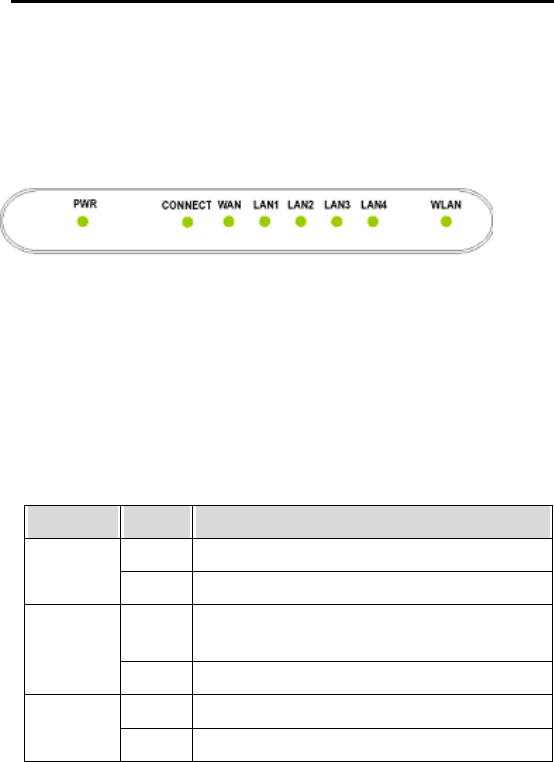
The following illustration shows the front panel of the Wireless
Broadband Router:
Figure 2-1 LED Indicator
LED Indicator
The Wireless Broadband Router is equipped with eight LEDs on
the front panel as described in the table below (from left to right):
LEDs Status Description
Off No power is supplied to the unit.
PWR Solid Power is connected to the unit.
Off Both WAN and ISP are not connected at the
same time.
CONNECT
Solid Both WAN and ISP are connected.
Off WLAN interface is not initialized properly.
WLAN
On WLAN interface is initialized properly and ready.
Wireless Broadband Router User Manual
6
LEDs Status Description
Blinking Transmitting/receiving packets wirelessly.
Off No broadband device is connected.
On Broadband device is connected.
WAN
Blinking Transmitting/receiving packets on the WAN port.
Off No Ethernet device is connected.
Solid Ethernet connection is established.
LAN 1-4
Blinking Transmitting/receiving packets on the LAN port.
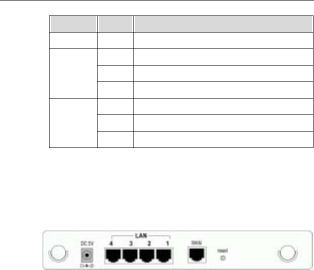
Rear Panel and Connector
The following illustration shows the rear panel of the Wireless
Broadband Router.
Figure 2-2 Rear Panel and Connector
• 12VAC: Power jack
• LAN Ports 1-4: RJ-45 Connector. Integrated 4-port
10/100BaseT switch. Connects to a hub, switch or
NIC-equipped PC in your network. The LAN ports has
Auto-MDI/MDIX feature that supports either crossover or
straight-through cables.
• Internet/WAN: RJ-45 connector. Connects to the
Cable/ADSL Modem. The WAN port also has Auto-MDIX
feature that supports either crossover or straight-trough
cables.
• LOAD DEFAULT: To restore to the factory default settings
insert a straightened paperclip into the hole to press the
button. Keep pressing and power cycle (off and on) the
device. Wait for at least 5 seconds to release the button.
Then wait for the device to finish booting. This operation
erases all previous settings entered by the administrator.

2. Hardware Description & Installation
7
2.2 Hardware Connection
Choosing a Place for the Wireless Broadband
Router
• Place the device close to the power outlet for the cable to
reach it easily.
• Avoid placing the device in places where people may walk
on the cables.
• Keep the device away from direct sunshine or heat
sources.
• Place the device on a flat and stable stand.
Connecting the Wireless Broadband Router
Prior to connecting the hardware, make sure to power off your
Ethernet device, Cable/ADSL modem and Wireless Broadband
Router. Then follow the steps below to connect the related devices.
Step 1 Connecting wired device to the LAN port.
Attach one end of the Ethernet cable with RJ-45
connector to your hub, switch or a PC’s Ethernet port, and
the other end to the LAN port of the Wireless Broadband
Router.
Step 2 Connecting Cable/ADSL Modem to the WAN port.
Connect the Ethernet cable attaching to your Cable/ADSL
modem to the WAN port of your Wireless Broadband
Router.
Step 3 Connecting the power adapter.
Connect one end to the power jack of the Wireless
Broadband Router and the other end to an AC outlet.
Caution
Only use the adapter supplied with the Wireless
Broadband Router. Connecting another adapter may
cause permanent damage to the device.
Wireless Broadband Router User Manual
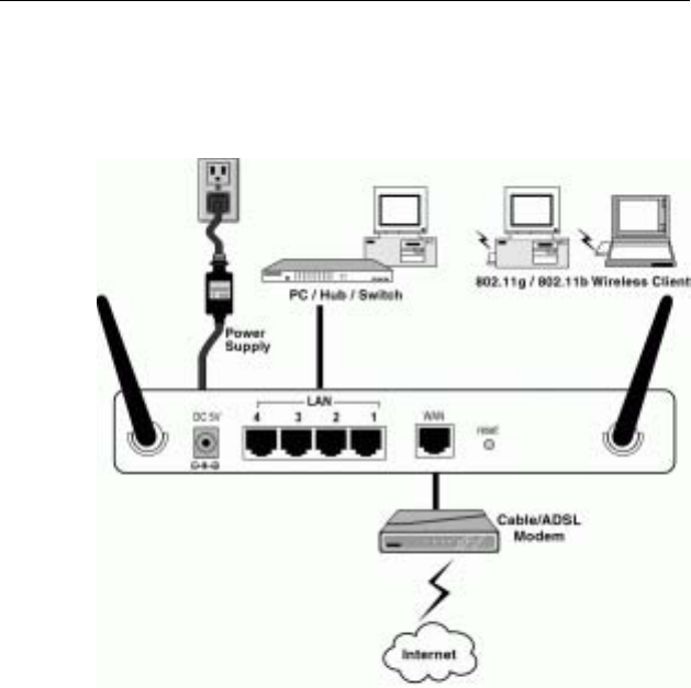
8
The illustration below specifies a connection diagram example:
Figure 2-3 Typical Connection Diagram

9
3 Configuring Local Computer to
Access the Wireless Router
This chapter describes how to configure a computer for initial
connection to the device.
3.1 Overview
To access the Wireless Broadband Router’s Web-based
Configuration Utility, at least one properly configured PC must be
connected to the device and resided on the same subnet with the
Wireless Broadband Router. The easiest way to make the
connection is attaching your host computer’s NIC directly to the
LAN port of the device, though it is also allowed to configure the
device via a wireless client.
Whatever your connection method is, the computer’s Ethernet
/wireless interface must be on the same subnet as the router. As
the Wireless Broadband Router is configured with these default
values:
• IP address: 192.168.2.1
• Subnet mask: 255.255.255.0
• DHCP server: Enabled with the IP address pool from
192.168.2.2 to 192.168.2.100.
So you should set up your NIC or wireless adapter’s TCP/IP
settings as one of the following:
1. To use dynamic IP: Set your PC to be DHCP client to accept
the dynamic IP from the router’s DHCP server.
2. To use static IP: Set the IP address as 192.168.2.x (x is
between 2 and 254), subnet mask as 255.255.255.0 and the
gateway as 192.168.2.1
The default TCP/IP setting for Windows is acting as a DHCP client.
Please proceed to the next section to verify or, if necessary, to
configure the TCP/IP settings.
Wireless Broadband Router User Manual
10
3.2 Setting up TCP/IP
Before proceeding, make sure your computer is equipped with
Ethernet network card or wireless adapter and has appropriate
network card driver and TCP/IP installed.
Note
1. If TCP/IP protocol is not installed on your PC, refer to
Windows documentations for installation instructions.
2. For initial configuration, it’s recommended to connect
only one PC directly to the LAN port on the Wireless
Broadband Router.
For Windows 98/ME
Step 1 Click on the Start menu, point to Settings and click on
Control Panel.
Step 2 Double-click the Network icon.
Step 3 In the Network window, highlight TCP/IP protocol for your
NIC or wireless adapter and click Properties.
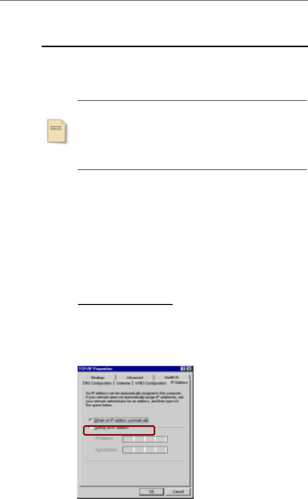
Step 4 Choose one of the methods as required:
Option A: Using DHCP
On the IP Address tab, select Obtain an IP address
automatically.
Then an IP address will be automatically assigned to your
computer.
3. Configuring Local Computer to Access the Wireless Router
11
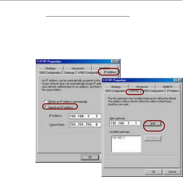
Option B: Using Fixed IP Address
• On the IP Address tab, select Specify an IP address.
• Then set the IP address as 192.168.2.x (x is between 2
and 254), subnet mask as 255.255.255.0.
• Select the Gateway tab and set the gateway to
192.168.2.1.
Step 5 Click OK twice to finish the configuration. If prompted to
restart your computer, click Yes.
(1)
(2)
(3)
(4)
Wireless Broadband Router User Manual
12
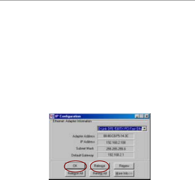
Check/Renew IP Address under Windows 98/ME
The following steps help you to verify if your network adapter gets
an IP address within the DHCP IP pool range (192.168.2.2 ~
192.168.2.100 by default) of the router. If not, you may need to
renew the IP information.
Step 1 From the Start menu, click Run to open the Run dialog
box.
Step 2 Enter winipcfg in the dialog box and then click OK.
Step 3 Select the Ethernet or WLAN adapter from the drop-down
list to show the IP address. If necessary, click Release
and then Renew to get a new IP address.
For Windows 2000/XP
Step 1 Click on the Start menu, point to Settings and click on
Control Panel.
Step 2 Double-click the Network and Dial-up Connections or
Network Connections icon.
Step 3 Right-click the Local Area Connection icon for your NIC
or wireless adapter and then click Properties.
Step 4 On the General tab, highlight Internet Protocol (TCP/IP)
and then click Properties.
Step 5 Choose one of the methods as required:
3. Configuring Local Computer to Access the Wireless Router
13
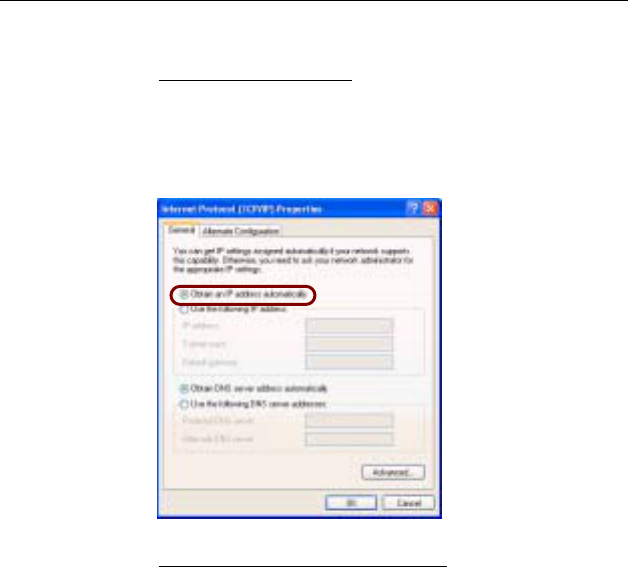
Option A: Using DHCP
On the IP Address tab, enable Obtain an IP address
automatically and then click OK.
Then an IP address will be automatically assigned to your
computer.
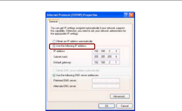
Option B: Using Fixed IP Address
Select Use the following IP address and enter these
settings:
• IP address: 192.168.2.x (x is between 2 and 254)
• Subnet mask: 255.255.255.0
• Default Gateway: 192.168.2.1
Wireless Broadband Router User Manual
14
Check/Renew IP Address under Windows 2000/XP
The following steps help you to verify whether the network adapter
gets an IP address within the DHCP IP pool range (192.168.2.2 ~
192.168.2.100 by default) of the router. If not, you may need to
renew the IP information.
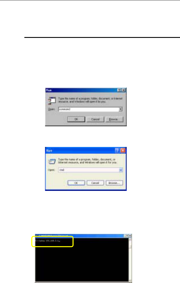
Step 1 Click Run from the Start menu to open the Run dialog
box.
Step 2 Type cmd in the dialog box and then click OK.
Step 3 At DOS command prompt, type ipconfig to see the IP
information from DHCP server.
Step 4 If you want to get a new IP address, type ipconfig
/release to release the previous IP address and then type
ipconfig /renew to get a new one.

3. Configuring Local Computer to Access the Wireless Router
15
3.2 Additional Settings for Wireless Client
If you choose to access the router via a wireless client, also verify
the following:
1. Make sure your PC is equipped with 802.11g or 802.11b
wireless adapter and has appropriate WLAN card driver/utility
and TCP/IP installed.
2. Set the wireless adapter to use appropriate TCP/IP settings as
described in previous section.
3. Launch the wireless adapter’s provided utility and verify that
your wireless client is configured with these settings:
• Operation Mode: Infrastructure
• SSID: wireless
• Authentication: Open
• WEP Mode: Disabled
Wireless Broadband Router User Manual
16
3.3 Checking Connection with the Wireless
Broadband Router
You can use the PING command to verify whether or not the
Ethernet/Wireless client can communicate with the device.
1. Open the DOS command window.
• For Windows 98/Me: Start > Run. Type command and
click OK.
• For Windows 2000/XP: Start > Run. Type cmd and click
OK.
2. Type the ping command and enter the IP address of the
Wireless Broadband Router. The factory default value is:
192.168.2.1. If you have changed the IP of the device, then
type the new IP address of the Wireless Broadband Router.
For example: C:\ping 192.168.2.1
3. Configuring Local Computer to Access the Wireless Router
17
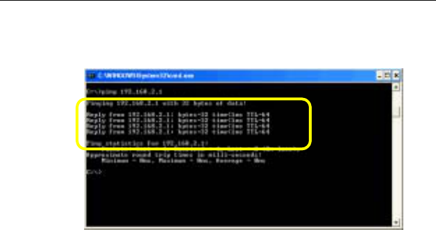
3. The Wireless Broadband Router shall reply and a similar
screen as below is shown.
This indicates the Wireless Broadband Router and the
wired/wireless host can be communicated. If you get a failed
ping response such as:
Request time out
Request time out
Request time out
Request time out
or
Destination host unreachable
Destination host unreachable
Destination host unreachable
Destination host unreachable
Then the connection has failed. Verify whether the network
setting is correct. For Ethernet client, also check the cable
between the router and the PC. Restart the computer if
necessary.
19
4 Web Configuration
4.1 Accessing Web-Based Configuration Utility
Once your PC is properly configured as described in "3.Configuring
Local Computer to Access the Wireless Router”, you can proceed
as follows for initial configuration:
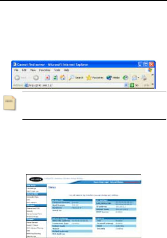
1. Start your Web browser and type http://192.168.2.1 in the
Address field. This address is the default private IP of your
router.
Note
If the router’s LAN port has been changed with a new IP
address, enter the new IP instead.
2. After enter the configuration screen, the Status home page
will appear below. At the top of the screen, there are three
tabs: Home, Help and Login/Logout to specify that get back
to home page (Status page), glossary of terms and
login/logout the configuration. And the Internet Status at the
near location will also show you the connection situation.
Figure 4-1 Status
Wireless Broadband Router User Manual
20
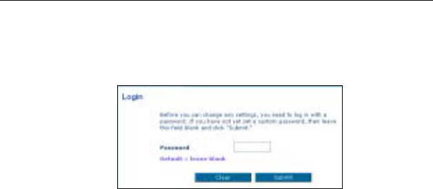
3. When select any main tab at the left of the screen will be
prompted with the following screen, leave the password empty,
and then click Submit.
Figure 4-2 Login
After successful login, you will be able to see the Wireless
Broadband Router’s web-based configuration utility. From now on
the Wireless Broadband Router acts as a Web server sending
HTML pages/forms on your request. You can click the item you
need to start the configuration screen.
4. Web Configuration
21
4.2 LAN Setup
The Router is equipped with a DHCP server that will automatically
assign IP addresses to each computer on your network, If you want
to changes the default values, please click “LAN Settings” on the
LAN tab to the left of the screen. Or you can also click “DHCP
Client List” on the LAN tab to the left of the screen to review the
list of all client computers connected to the network.
LAN Settings
This page allows you to make changes to the LAN, after the
changes you have configured, click Apply Changes to take effect
or click Clear Changes to erase the changes. During the
configuration, you can also click More Info to get more detail
information relates to the item or sentence indicated.
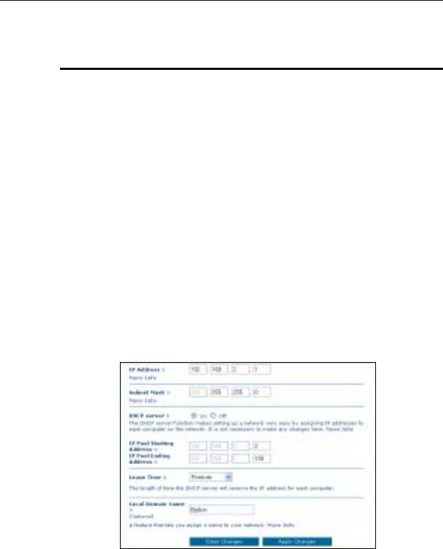
Figure 4-3 LAN Settings
The LAN Settings interface includes the items configuration
described below:
IP Address/Subnet Mask
Enter the IP address and subnet mask for the Wireless Broadband
Router LAN port. All local wired/wireless devices communicate with

Wireless Broadband Router User Manual
22
the device through this port. It is also the IP address of the
Web-based Configuration Utility. By default, the IP address and
subnet mask of the LAN port is 192.168.2.1 and 255.255.255.0
respectively. Note that if you change the private IP address and
apply the changes, the PC from which you configure the router will
lose the communication to the router. To reconnect, you will need
to renew the IP address of the PC or change to an IP address
compatible with the new LAN port IP address.
DHCP Server (Router Mode Only)
Select whether to enable DHPC service for LAN and WLAN. The
Wireless Broadband Router implements a built-in DHCP (Dynamic
Host Configuration Protocol) server on its LAN and WLAN interface,
which dynamically assigns IP addresses to the DHCP clients on
the LAN / WLAN. The DHCP server also provides a default
gateway (the router’s LAN IP address) and DNS addresses for
DHCP clients to access the Internet. DHCP function spares you the
hassle of manually assigning a fixed IP address to each PC on the
LAN / WLAN. If you already have a DHCP server on your network
you should disable this function. DHCP server is enabled by
default.
IP Pool Starting/Ending Address: Specify the starting and ending
IP address of the IP address pool. Whenever a network device
requests an Internet session, the router will allocate an unused IP
address from this pool and lease them to the device for a specified
amount of time.
Lease Time
Specify the length of time that the DHCP server will reserve the IP
address for each computer.
Local Domain Name (Optional)
A feature that allows you can assign a name to your network.

4. Web Configuration
23
DHCP Client List
This page can show you the IP address, Host Name and MAC
address of each computer connected to your network. You can
click Refresh to update the latest list.
Figure 4-4 DHCP Client List
Wireless Broadband Router User Manual
24
4.3 Internet WAN
This tab allows you to set up your Router to connect to your
Internet Service Provider. The Router is capable of connecting to
virtually any Internet Service Provider’s system provided that you
have correctly configured the Router’s settings for your ISP’s
connection type. You can click “Connection Type” on the Internet
WAN tab on the left of the screen to configure the Router to
connect to your ISP.
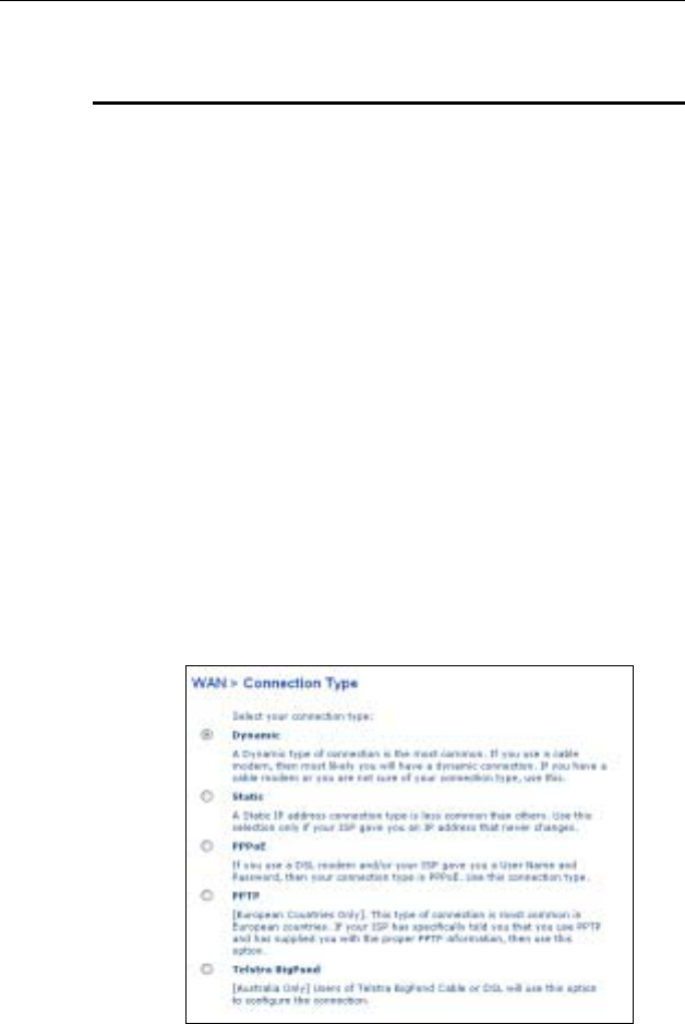
Connection Type
There are five connection types supported by this Router: Dynamic,
Static, PPPoE, PPTP and Telstra BigPond. Each of them is
described as below, after selecting the connection type you want to
use, click Next to next related configuration page. After finishing
the configuration, you must click Apply Changes to take effect or
click Clear Changes to erase the settings. During the configuration,
you can also click More Info to get more detail information relates
to the item or sentence indicated.
Figure 4-5 Connection Type
4. Web Configuration
25
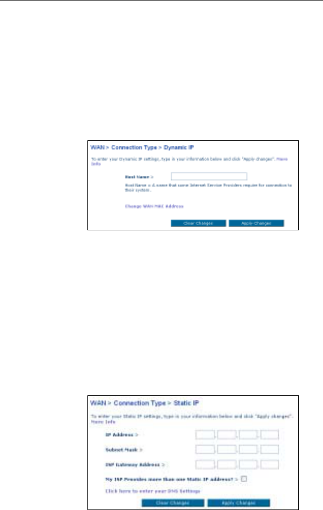
Dynamic
This connection type is the most common method. If you are using
a cable modem for connection or not sure what your connection
type is, please select this type to obtain the IP automatically.
Click Next to enter Dynamic IP configuration page, type in the host
name that is connected to the Internet Service Providers to the
Host Name field.
Figure 4-6 Dynamic IP
Static
This connection type is less common than others. Only under the
ISP give you an IP address that is fixed and never be changed,
please select this type.
Click Next to enter Static IP configuration page, type in the static
IP address, subnet mask and ISP gateway address to the related
fields. You can also select the “My ISP Provides more than one
Static IP address?” checkbox to add another static IP address.
Figure 4-7 Static IP
Wireless Broadband Router User Manual
26
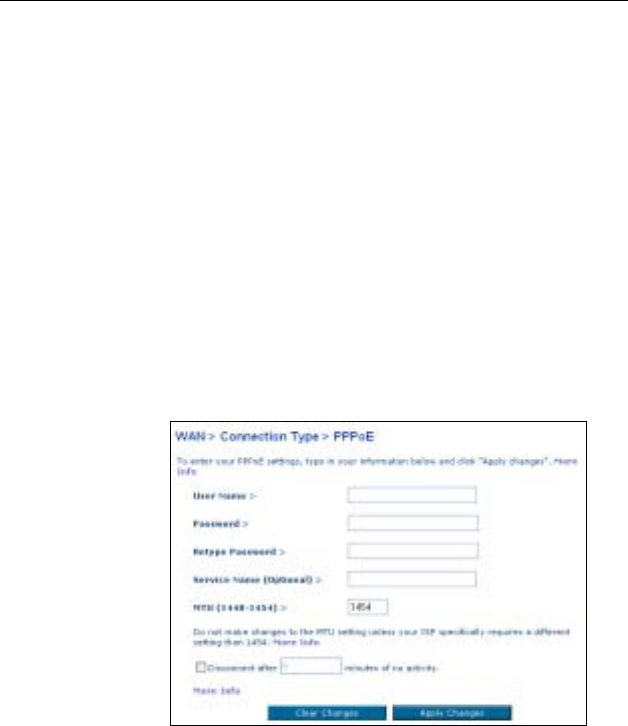
PPPoE
When you use a DSL modem and/or your ISP give you a User
Name and Password, then your connection type is PPPoE, please
select this type.
Click Next to enter PPPoE configuration page, type in the user
name and password supplied by your ISP to the User Name and
Password fields. Retype in the password to the Retype Password
field. If you do not have a service name or do not know it, please
leave the Service Name field blank. About MTU field, please do
not make any change unless your ISP specifically requires a
different setting that 1454. You can also select the “Disconnect
after x minutes of no activity.” checkbox to set the idle time for
disconnection.
Figure 4-8 PPPoE
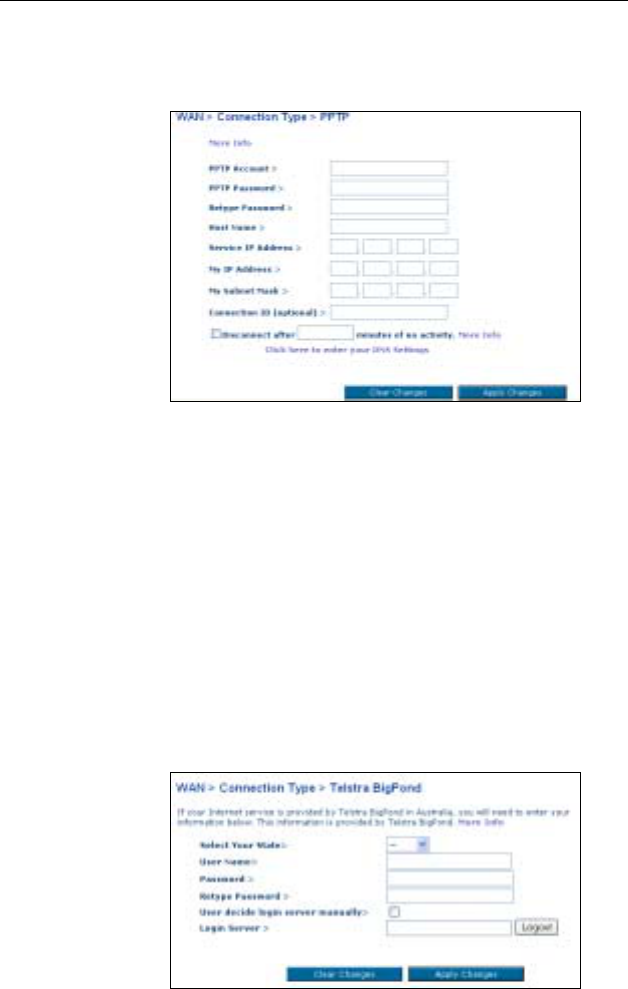
PPTP (Only for Europe)
In Europe, this connection type is the most common method. If you
ISP has specified you to use PPTP and supplied you with the
proper PPTP information, please select this type.
Click Next to enter PPTP configuration page, type in the
information supplied by your ISP to the related fields. Retype in the
password to the Retype Password field. You can also select the
4. Web Configuration
27
“Disconnect after x minutes of no activity.” checkbox to set the
idle time for disconnection.
Figure 4-9 PPTP
Telstra BigPond (Only for Australia)
In Australia, users of Telstra BigPond Cable or DSL will use this
type to configure the connection.
After selecting this type and click Next to enter Telstra BigPond
configuration page, type in the information supplied by Telstra
BigPond to the related fields. The Login Server IP address will be
filled in automatically according to what state you choose. If your
Login Server address is different than one provided here, please
select the “User decide login server manually” checkbox to
enter the Login Server IP address manually.
Figure 4-10 Telstra BigPond
Wireless Broadband Router User Manual
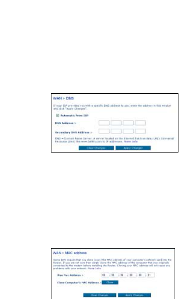
28
DNS
If your ISP provides you a specific DNS address to use (using a
Static IP connection type), in this page, enter the specific DNS
address and secondary DNS address for your connection to work
properly. On the other hand, if your connection type is Dynamic or
PPPoE that mean your ISP will not provide you a specific DNS
address to use, please select the “Automatic from ISP”
checkbox.
Figure 4-11 DNS
MAC Address
In this page, if you are not sure whether your ISP needs to see the
original MAC address, simply copy the MAC address of the
computer that was originally connected to the modem. Copying the
address will not cause any problems with your network. Click the
Clone to copy your MAC address, make sure that you are using
the computer that was ORIGINALLY CONNECTED to your
modem before the Router was installed.
Figure 4-12 MAC address

4. Web Configuration
29
4.4 Wireless
In this tab, you can adjust Channel and SSID, Security, USE as
Access Point and Wireless Bridge to the wireless section of the
Router.
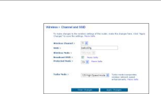
Channel and SSID
Wireless Channel/SSID/Wireless Mode
Select the desired channel from the drop-down list attached to the
Wireless Channel. The SSID is the equivalent to the wireless
network’s name; you can also name the SSID. If there are other
wireless networks in your area, you should give your wireless
network a unique name. The default is belkin54g.
Broadcast SSID
Select this item’s checkbox can show your SSID to the network. If
you don’t want your network to appear in a site survey, please
don’t select this item’s checkbox for increasing security.
Protected Mode
In most situations, best performance (throughput) is achieved with
Protected Mode OFF. If you are operating in an environment with
HEAVY 802.11b traffic or interference, best performance may be
achieved with Protected Mode ON.
Turbo Mode
This router supports 1 mode:
• Frame Bursting mode: Frame Bursting mode is based
on the unreleased 802.11e specification for supporting
both Frame Bursting enabled devices and non Frame
Bursting enabled devices simultaneously. Select this
mode will make all devices capable of Frame Bursting to
Wireless Broadband Router User Manual
30
function in frame bursting mode, and all clients not
capable to operate in normal 802.11g modes.
Figure 4-13 Channel and SSID
4. Web Configuration
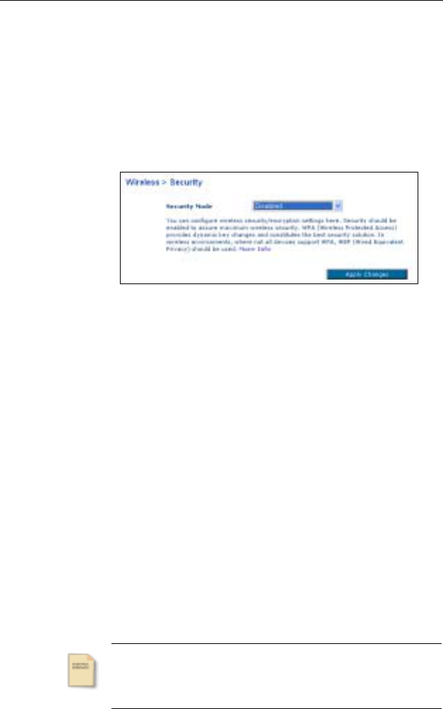
31
Security
Security page allows you to configure wireless security/encryption
settings for the wireless. Select the security mode you need from
the drop-down list, than click Apply Changes to enter next related
configuration page.
Figure 4-14 Security
Disabled
Select this mode to disable any encryption.
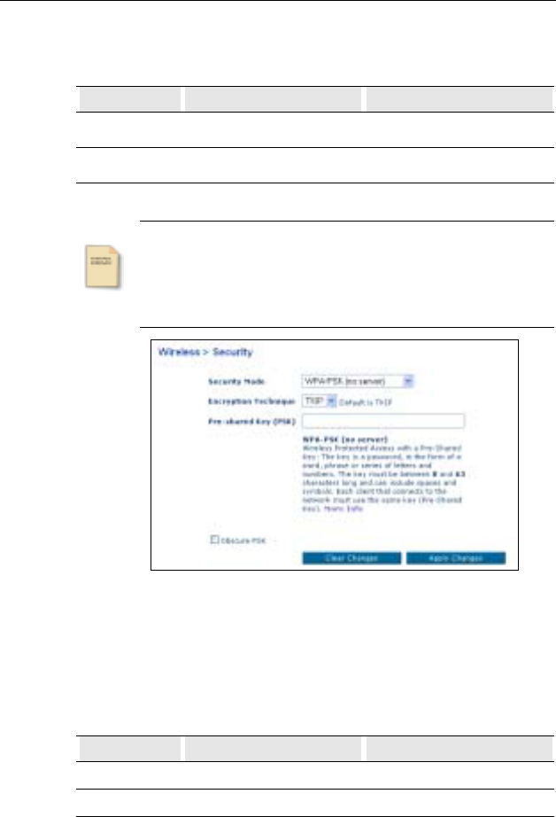
WPA-PSK (no server)
WPA-PSK is for home and small business users who don’t have a
server. And the encryption technique includes TKIP and AES. The
default value is TKIP.
• TKIP: This encryption technique can provide better
compatibility between wireless products from different
vendors since many wireless products will never be
upgraded to AES.
• AES: AES is a new encryption technique based on the
un-ratified 802.11i standard. New WPA standard are being
considered using AES. Although AES is not as popular,
some users may prefer to use this technique.
Note
No matter what encryption technique you use, all
networks devices must use the same technique.
Wireless Broadband Router User Manual
32
After selecting the Encryption Technique you want to use, type in
the password to the “Pre-shared Key (PSK)” field.
Format Minimum Characters Maximum Characters
ASCII 8 63
Hexadecimal 8 64
Note
1. The password is distinction between uppercase and
lowercase.
2. The same PSK must also be used for every other
wireless network device on the network.
Figure 4-15 WPA-PSK
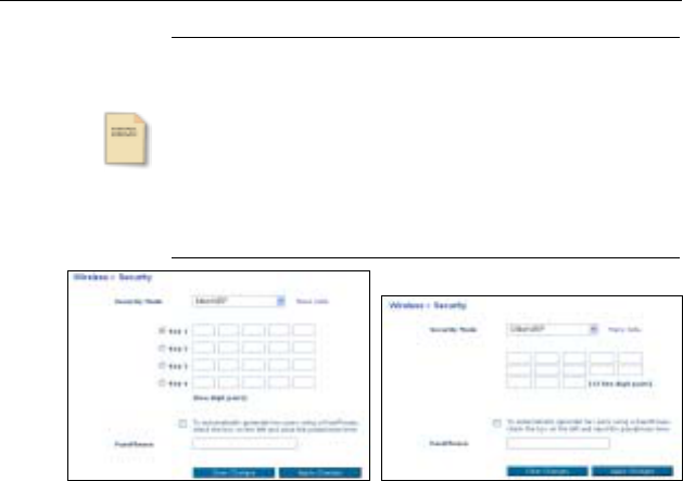
WEP
This mode includes 128bit WEP and 64bit WEP described as
below:
Key Length HEX Format ASCII Format
64 Bit 10 hexadecimal digits 5 ASCII characters
128 Bit 26 hexadecimal digits 13 ASCII characters
4. Web Configuration
33
Note
1. If you have defined a WEP key on the router, you
have to make this key known to the network adapters
on the PCs that are to be logged on your router.
Otherwise it will not be possible to set up a
connection between the PC and your router.
2. The encryption depth (64 or 128 bits) must be the
same on the router and on the wireless network
adapters of the PCs.
Figure 4-16 WEP 64bit and 128bit
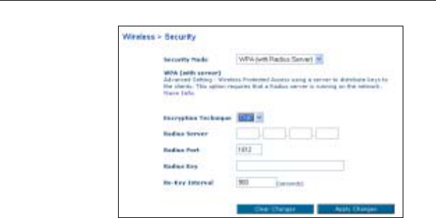
WPA
Encryption Technique: Include TKIP and AES; both of them are
Only for WPA and WPA-PSK. Please refer to WPA-PSK for more
information.
Radius Server: For 802.1X and WPA only. Enter the IP Address
of the authentication server, commonly the Radius server.
Radius Port: Enter the port number of the authentication server.
The default port number is 1812.
Radius Key: Enter the same key as the Radius server’s.
Re-Key Interval: Specify the timer the WPA key must changes.
The change is done automatically between the server and the
client.
Wireless Broadband Router User Manual
34
Figure 4-17 WAP
4. Web Configuration
35
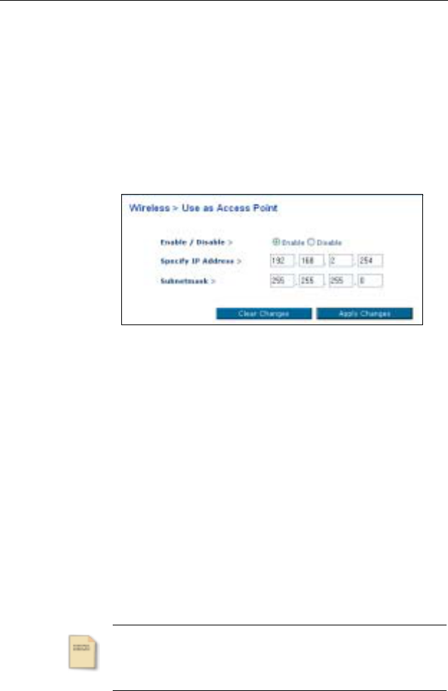
Use as Access Point
When using the router as an Access Point, you must specify an IP
address for the Access Point. To do this, please select Enable item
to enter the IP address and Subnetmask configuration page. Type
in the IP address and Subnetmask that must suit to the same
range as the network that you will connect to.
Figure 4-18 User as Access Point
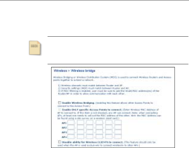
Wireless Birdge
Wireless Bridging or wireless Distribution System (WDS) is used to
connect Wireless Routers and Access points together to extend a
network. There are three settings in this page:
Enable Wireless Bridging checkbox: Enabling the wireless bridge
feature to allow other Access Points to connect to your device.
Enable ONLY specific Access Point to connect checkbox:
Select this item so that you can type the specific Access Point’s
MAC address in the related fields for limiting specific Access Point
connected by you.
Note
This item can be selected only under the Enable
Wireless Bridging checkbox is enabled.
Wireless Broadband Router User Manual
36
Disable ability for Wireless CLIENTS to connect checkbox:
When the AP is used exclusively to connect wirelessly to other APs,
please select this item.
Note
Bridging mode cannot be enabled when using 125
High-speed Mode. To enable bridging, first go to
“Channel and SSID” and select another Turbo mode.
Figure 4-19 Wireless Bridge
4. Web Configuration
37
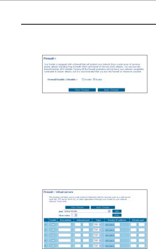
4.5 Firewall
This Router is equipped with a firewall to protect your network from
some hacker attacks. For protection you network, we suggest you
it is better to enable this function.
Figure 4-20 Firewall
Virtual Servers
This function allows you to route external (Internet) calls for
services such as a web server (port 80), FTP server (Port 21), or
other applications through your Router to your internal Network. If
you want to configure the Virtual Server function for a specific
application, you can select your application from the drop-down list
and then click Add. Or contact the application vendor to find out
which port settings you need when the application is not listed. You
can also clear the designate entry from the related drop-down list
and click Clear.
Figure 4-21 Virtual Servers
Wireless Broadband Router User Manual
38
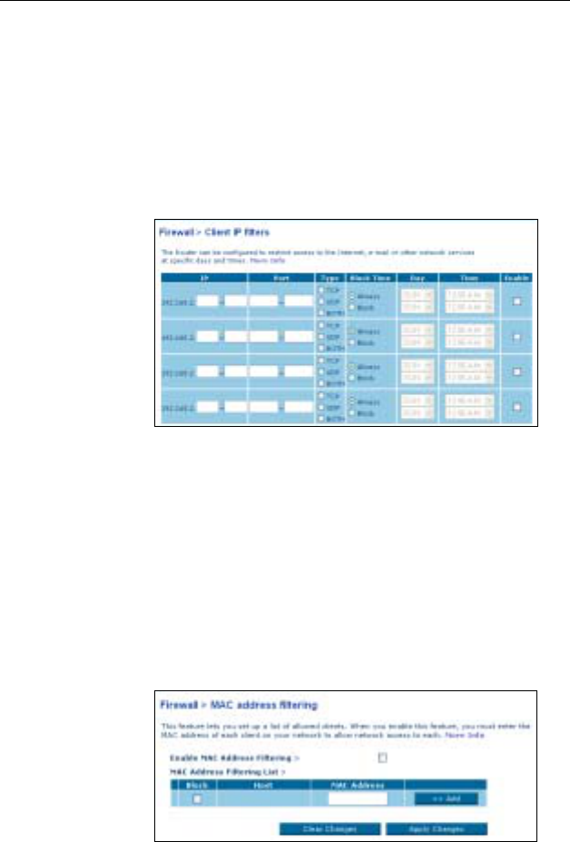
Client IP Filters
No matter a single PC, a range of PCs, or multiple PCs can be
configured to restrict access to the Internet. This page allows you
to restrict which PCs can access the Internet including e-mail or
other network services at specific days and times.
Figure 4-22 Client IP Filters
MAC Address Filtering
This page allows you to specify which PCs are allowed to access
the network. Any PC is not specified in the filter list will be denied
access. Using this function, you have to select the “Enable MAC
Address Filtering” checkbox. The “Block” feature allows you to
turn on and off access between PC and network easily.
Figure 4-23 MAC Address Filtering
4. Web Configuration
39
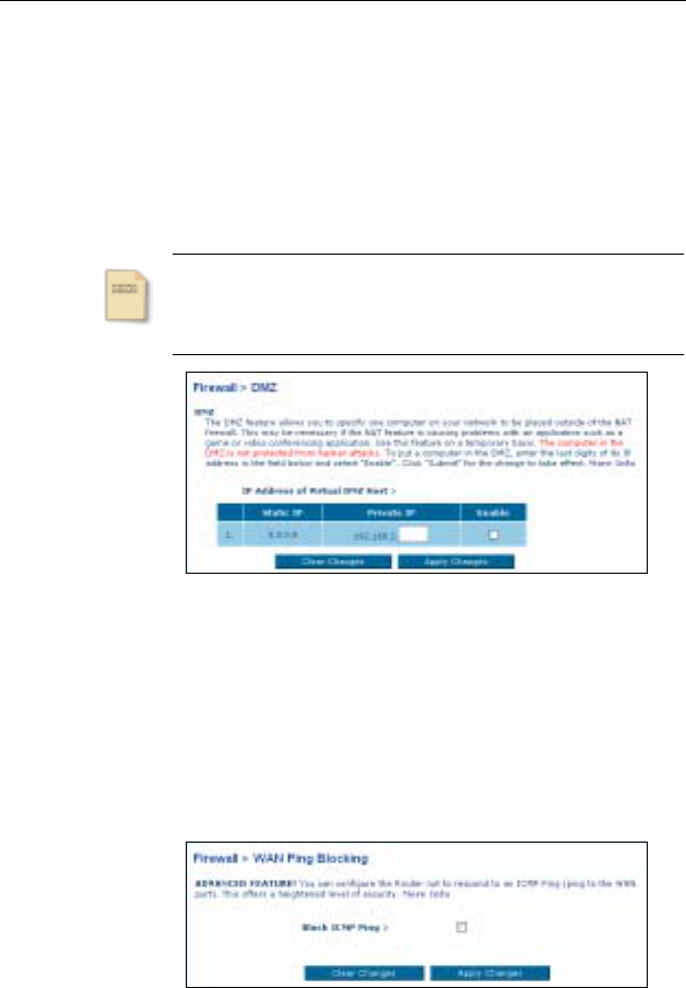
DMZ
In the IP address of Virtual DMZ Host configuration box, enter the
last digits of the specific IP address in the Private IP field. Then,
select Enable checkbox for enabling the DMZ host computer to
send all traffic from all ports.
Note
The PC in the DMZ is not protected from hacker attacks.
Figure 4-24 DMZ
WAN Ping Blocking
For a heightened level of security, you can configure the Router not
to respond to an ICMP Ping (ping to the WAN port). Select “Block
ICMP Ping” checkbox to turn off the ping response.
Figure 4-25 WAN Ping Blocking
Wireless Broadband Router User Manual
40
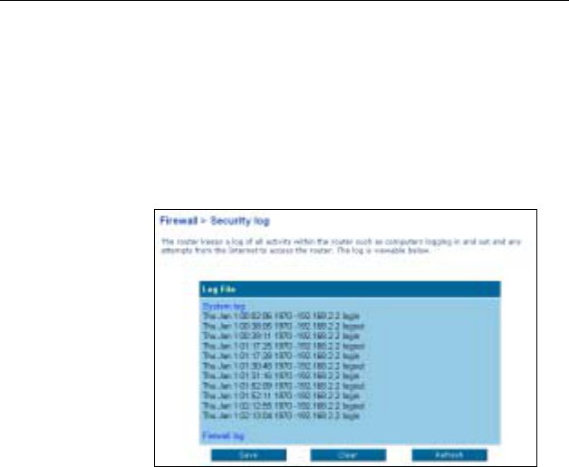
Security log
This page will list a log of all activity kept in the router, including
computer log in, log out and any attempts from the Internet to
access the router logs. Click Refresh to renew the logs; click Clear
to erase all the logs or Save to keep the logs in the router.
Figure 4-26 Security Log
4. Web Configuration
41
4.6 Utilities
This tab includes Parental control, Restart Router, Restore
Factory Defaults, Save/Backup Current Settings, Restore
Previous Saved Settings, Firmware Update and System
Settings functions.
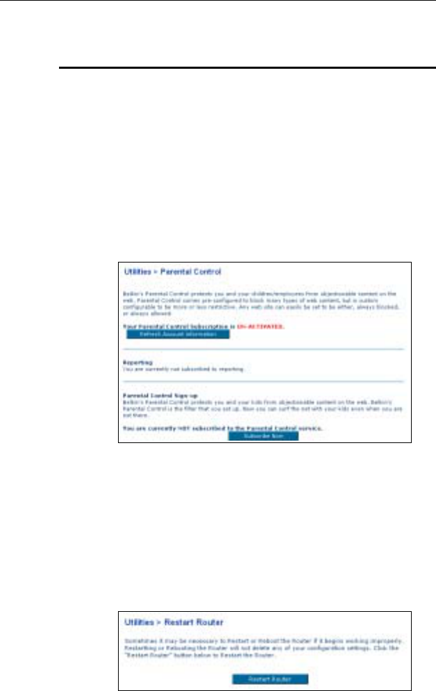
Parental Control
The Router supports Parental Control function to protect you and
your children/employees from objectionable content on the web.
Figure 4-27 Parental Control
Restart Router
Whenever you want to Restart or Reboot the Router if it works
improperly, you can go to this page to click the Restart Router
button to restart the router. Using this function will not erase any
configurations that you have made.
Figure 4-28 Restart Router
Wireless Broadband Router User Manual
42
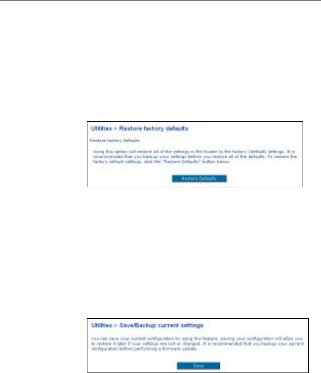
Restore Factory Default
Click Restore Defaults button to restore all the configurations that
you have made to the factory default. After using this function, all
the settings you made will be erased. Therefore, we suggest you to
backup your settings before you restore all of the defaults.
Figure 4-29 Restore Factory Defaults
Save/Backup Settings
Before you make any change about settings, we suggest you to
backup your current configurations. Saving your configurations can
help you to restore the previous settings when your settings are
lost or changed. Click Save button to save the configurations.
Figure 4-30 Save/Backup Current Settings
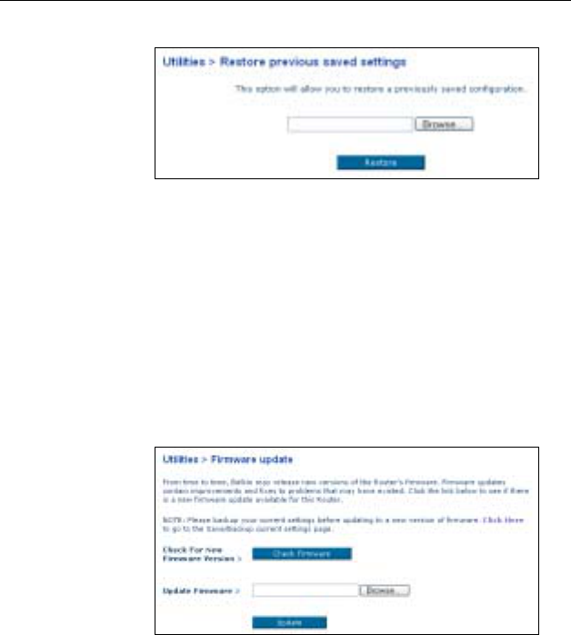
Restore Previous Settings
This page allows you to restore a previously saved configuration.
Click Browse button to load the file, then click Restore button to
activity this function.
4. Web Configuration
43
Figure 4-31 Restore Previous Saved Settings
Firmware Update
If you want to update your firmware version, please click the Check
Firmware button to search for new firmware version. Then, click
Browse to load the firmware version that you have downloaded
and saved in your hardware. Click Update button to activity
firmware update function.
Figure 4-32 Firmware Update
Wireless Broadband Router User Manual
44
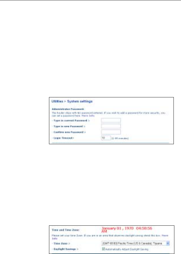
System Settings
This page includes some management settings:
Administrator Password
There is NO any password entered when the Router is shipped.
You can add a password for more security. The Login Timeout
allows you to set the period of time that you can be logged into the
Router’s advanced setup interface.
Figure 4-33 Administrator Password
Time and Time Zone
The router is connected to a Simple Network Time Protocol (SNTP)
server for keeping time so that it can synchronize the system cock
to the global Internet. Select the time zone that you reside in from
the Time Zone drop-down list. If your residence zone observes
Daylight Saving, please also select the “Automatically Adjust
Daylight Saving” checkbox.
Figure 4-34 Time and Time Zone
4. Web Configuration
45
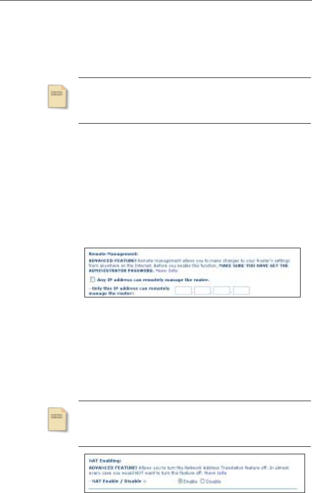
Remote Management (Advanced Feature)
This function allows you to make changes to your Router’s settings
from anywhere on the Internet.
Note
Before you use this function, please make sure you have
set the administrator password.
Remote management includes two methods:
Any IP address can remotely mange the router checkbox:
Select this item will allow you to access to the router from
anywhere on the Internet.
Only this IP address can remotely manage the router fields:
Type in the IP address that you want to use to remotely manage
the router.
Figure 4-35 Remote Management
NAT Enabling (Advanced Feature)
If you have a single IP address and you turn NAT off, the
computers on your network will not be able to access the Internet.
Other problems may also occur. Turning off NAT will disable your
firewall functions.
Note
Before you use this function, please make sure you have
set the administrator password.
Figure 4-36 NAT Enabling
Wireless Broadband Router User Manual
46
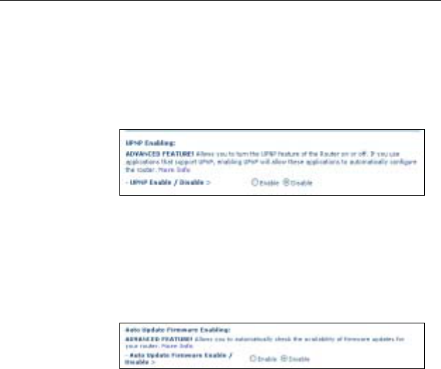
UPNP (Advanced Feature)
If you want to use any applications that are UPnP compliant, and
wish to take advantage of the UPnP features, please enable the
UPnP function to automatically configure the router.
Figure 4-37 UPNP
Auto Update Firmware Enabling (Advanced Feature)
Enable this function will allow you to automatically check the
availability of firmware updates for your router.
Figure 4-38 Auto Update Firmware Enabling
47
5 Troubleshooting
I cannot access the Web-based Configuration Utility from the
Ethernet computer used to configure the router.
• Check that the LAN LED is on. If the LED is not on, check
the cable for the LAN connection is firmly connected.
• Check whether the computer resides on the same subnet
with the router’s LAN IP address.
• If the computer act as a DHCP client, check whether the
computer has been assigned an IP address from the
DHCP server. If not, you will need to renew the IP
address.
• Use the ping command to ping the router’s LAN IP
address to verify the connection.
• Make sure your browser is not configured to use a proxy
server.
• Check that the IP address you entered is correct. If the
router’s LAN IP address has been changed, you should
enter the reassigned IP address instead.
I can browse the router’s Web-based Configuration Utility but
cannot access the Internet.
• Check the WAN LED is ON. If not, check the physical
connection between the router and the DSL/Cable modem
is firmly connected. Also ensure the DSL/Cable modem is
working properly.
• If WAN LED is ON, open the System Overview page of
the Web configuration utility and check the status group to
see if the router’s WAN port has successfully obtained an
IP address.
• Make sure you are use the correction method (DHCP
client, PPPoE client or Manual Config) as required by the
ISP. Also ensure you have entered correct settings
provided by the ISP.

Wireless Broadband Router User Manual
48
• For cable users, if you ISP required a fixed Ethernet card
MAC address, make sure you have cloned the network
adapter’s MAC address to the WAN port of the router.
(See the MAC Address field in WAN page.)
My wireless client cannot communicate with another Ethernet
computer.
• Ensure the wireless adapter functions properly. You may
open the Device Manager in Windows to see if the
adapter is proper installed.
• Make sure the wireless client uses the same SSID and
security settings (if enabled) as the Wireless Broadband
Router.
• Ensure that the wireless adapter’s TCP/IP settings are
correct as required by your network administrator.
• If you are using a 802.11b wireless adapter, check that the
54g Mode item, in Wireless LAN (2.4G) page, is not
configured to use 54g Performace.
• Use the ping command to verify the wireless client’s
communication with the router’s LAN port and with the
remote computer. If the wireless client can successfully
ping the router’s LAN port but fails to ping the opposite
computer, then verify the TCP/IP settings of the opposite
computer.

49
6 Specification
6.1 Hardware
• Broadcom BCM4712 CPU
• 8MB SDRAM
• 2MB Flash Memory
• 802.11g: Broadcom (BCM2050)
• Two external antennas
• Modulation Techniques: DBPSK, DQPSK, CCK, 16QAM,
64QAM
• Modulation Technology: OFDM, DSSS
• Wireless Data Rate:
802.11b: 11, 5.5, 2, 1Mbps
802.11g: 54, 48, 36, 24, 18, 12, 9, 6Mbps
• RF Operating Frequencies: 2.4-2.4835GHz
• RF Operating Channels:
802.11b: 11 for North America, 13 for Europe (ETSI), 14
for Japan
802.11g: 11 for North America, 13 for Europe (ETSI), 13
for Japan
• RF Output Power: 13.5+-2dBm
• RF Receiver sensitivity (PET<10%): -80dBm @ 6Mbps
Interface
• One 10/100 Base-TX RJ-45 WAN port for Broadband
connection (Cable/DSL or direct Ethernet) and support HP
Auto-MDIX
• Four RJ-45 LAN ports for 10/100Base-TX Ethernet Switch
support HP Auto-MDIX

Wireless Broadband Router User Manual
50
Physical
• Front Panel: 8 LEDs ( Power x 1, CONNECTx1, LAN x 4,
WAN x 1, Wireless x 1)
• Back Panel: Reset Button, Power Jack, RJ-45 LAN Port x
4, RJ-45 WAN Port x 1
• Dimensions: TBD
• Case types: Support Lay down only
Power Adapter and Environmental Requirement
• DC Adaptor: Input AC100~120VAC Output 5V DC, 2A
• Temperature: 0 to 40°C (operation), -20 to 70 °C (storage)
• Relative Humidity: 5% to 90% (non-condensing)
Electromagnetic Compliance
• FCC Part 15 Class B
• CE