Belkin F5D8235-4B N+ Wireless Router User Manual Manual Part 2
Belkin International, Inc. N+ Wireless Router Manual Part 2
Belkin >
Contents
- 1. Manual Part 1
- 2. Manual Part 2
- 3. Manual Part 3
Manual Part 2
29
N+ Wireless Router
SECTIONSTable of Contents 1234 6789105
ALTERNATE SETUP METHOD
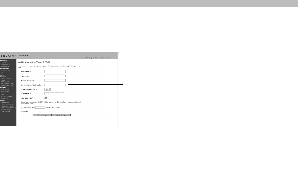
Setting your ISP Connection Type to PPPoE
Most DSL providers use PPPoE as the connection type. If you use a DSL modem to connect to the Internet, your ISP may use PPPoE to log you into
the service. If you have an Internet connection in your home or small office that doesn’t require a modem, you may also use PPPoE.
1. User Name
This space is provided to type in your user name that was assigned by
your ISP.
2. Password
Type in your password and retype it into the “Retype Password” box to
confirm it.
3. Service Name
A service name is rarely required by an ISP. If you are not sure if your
ISP requires a service name, leave this blank.
4. MTU
The MTU setting should never be changed unless your ISP gives you
a specific MTU setting. Making changes to the MTU setting can cause
problems with your Internet connection including disconnection from the
Internet, slow Internet access, and problems with Internet applications
working properly.
5. Disconnect after X...
The “Disconnect” feature is used to automatically disconnect the Router
from your ISP when there is no activity for a specified period of time. For
instance, placing a check mark next to this option and entering “5” into
the minute field will cause the Router to disconnect from the Internet
after five minutes of no Internet activity. This option should be used if
you pay for your Internet service by the minute.
Your connection type is PPPoE if:
1) Your ISP gave you a user name and password, which is required to
connect to the Internet.
2) Your ISP gave you software such as WinPOET or Enternet300 that
you use to connect to the Internet.
3) You have to double-click on a desktop icon other than your
browser to get on the Internet.
(1)
(2)
(3)
(4)
(5)
30
N+ Wireless Router
SECTIONSTable of Contents 1234 6789105
ALTERNATE SETUP METHOD
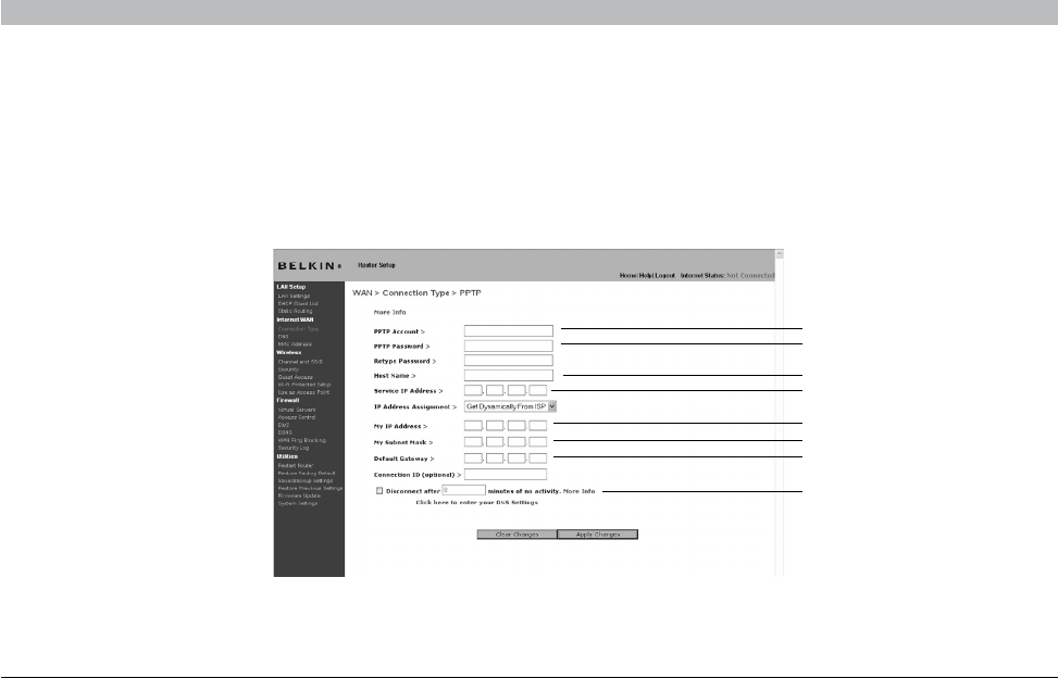
Setting your Internet Service Provider (ISP) Connection Type to Point-to-Point Tunneling Protocol (PPTP) [European Countries Only].
Some ISPs require a connection using PPTP protocol, a type of connection most common in European countries. This sets up a direct connection to
the ISP’s system. Type in the information provided by your ISP in the space provided. When you have finished, click “Apply Changes” (9). After you
apply the changes, the Internet Status indicator will read “connection OK” if your Router is set up properly.
(1)
(2)
(3)
(4)
(5)
(6)
(7)
(8)

31
N+ Wireless Router
SECTIONSTable of Contents 1234 6789105
ALTERNATE SETUP METHOD
1. PPTP Account
Provided by your ISP. Enter your PPTP account name here.
2. PPTP Password
Type in your password and retype it into the “Retype Password” box to
confirm it.
3. Host Name
Provided by your ISP. Enter your host name here.
The following becomes visible when you deselect “Get IP by DHCP”.
4. Service IP Address
Provided by your ISP. Enter your service IP address here.
5. My IP Address
Provided by your ISP. Enter the IP address here.
6. My Subnet Mask
Provided by your ISP. Enter the IP address here.
7. Default Gateway
Provided by your ISP. If your ISP did not give you a connection ID
(default gateway), leave this blank.
8. Disconnect after X…
The “Disconnect” feature is used to automatically disconnect the Router
from your ISP when there is no activity for a specified period of time. For
instance, placing a check mark next to this option and entering “5” into
the minute field will cause the Router to disconnect from the Internet
after five minutes of no Internet activity. This option should be used if
you pay for your Internet service by the minute.
32
N+ Wireless Router
SECTIONSTable of Contents 1234 6789105
ALTERNATE SETUP METHOD
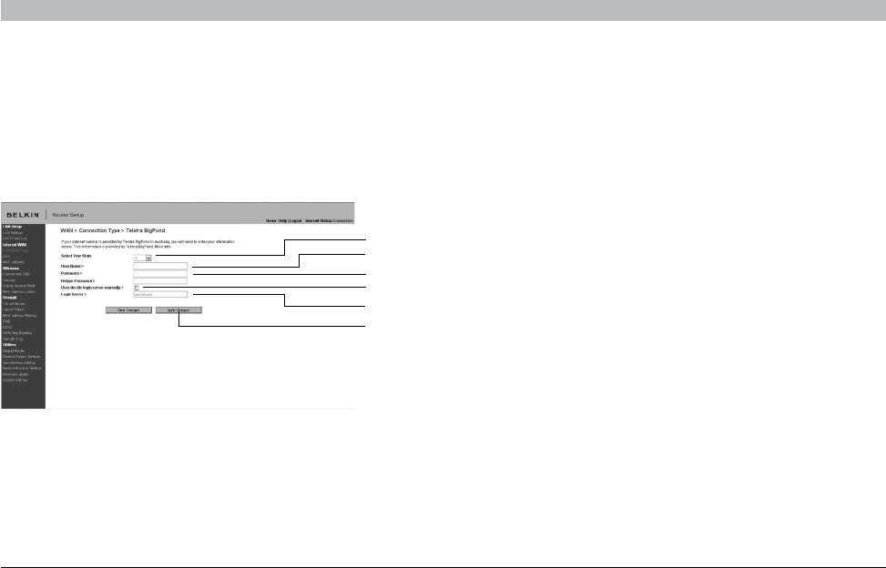
Setting your Connection Type if You Are a Telstra® BigPond User [Australia Only]
Your user name and password are provided to you by Telstra BigPond. Enter this information below. Choosing your state from the drop-down menu
(1) will automatically fill in your login server IP address. If your login server address is different than one provided here, you may manually enter the
login server IP address by placing a check in the box next to “User decide login server manually” (4) and type in the address next to “Login Server”
(5). When you have entered all of your information, click “Apply Changes” (7). After you apply the changes, the Internet Status indicator will read
“connection OK” if your Router is set up properly.
1. Select your State
Select your state from the drop-down menu (1). The “Login Server” box
will automatically be filled in with an IP address. If for some reason this
address does not match the address that Telstra has given, you can
manually enter the login server address. See “User decide login server
manually” (4).
2. User Name
Provided by your ISP. Type in your user name here (2).
3. Password
Type in your password and retype it into the “Retype Password” box (3)
to confirm it.
4. User Decide Login Server Manually
If your login server IP address is not available in the “Select Your
State” drop-down menu (1), you may manually enter the login server IP
address by placing a check in the box next to “User decide login server
manually” (4) and type in the address next to “Login Server” (5).
(1)
(2)
(3)
(4)
(5)
(7)
33
N+ Wireless Router
SECTIONSTable of Contents 1234 6789105
ALTERNATE SETUP METHOD
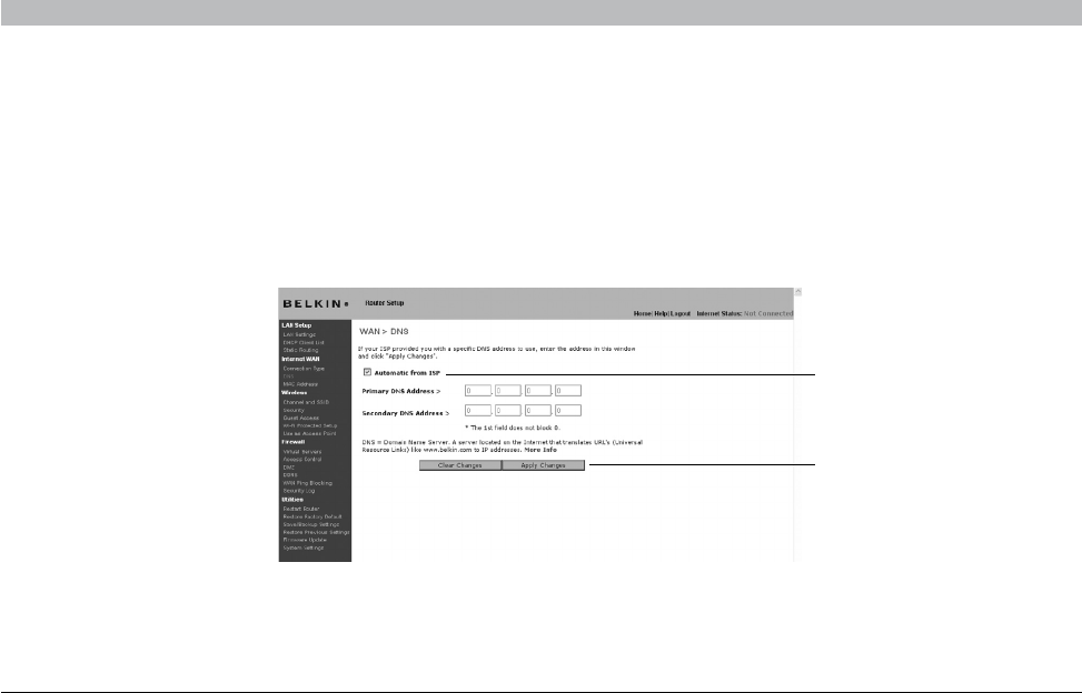
Setting Custom Domain Name Server (DNS) Settings
A “Domain Name Server” is a server located on the Internet that translates Universal Resource Locaters (URLs) like “www.belkin.com” to IP
addresses. Many Internet Service Providers (ISPs) do not require you to enter this information into the Router. The “Automatic from ISP” box (1)
should be checked if your ISP did not give you a specific DNS address. If you are using a static IP connection type, then you may need to enter a
specific DNS address and secondary DNS address for your connection to work properly. If your connection type is dynamic or PPPoE, it is likely that
you do not have to enter a DNS address. Leave the “Automatic from ISP” box checked. To enter the DNS address settings, uncheck the “Automatic
from ISP” box and enter your DNS entries in the spaces provided. Click “Apply Changes” (2) to save the settings.
(1)
(2)
34
N+ Wireless Router
SECTIONSTable of Contents 1234 6789105
ALTERNATE SETUP METHOD
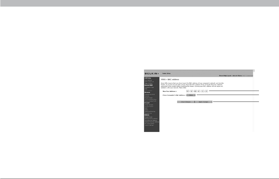
Configuring your WAN Media Access Controller (MAC) Address
All network components including cards, adapters, and routers, have
a unique “serial number” called a MAC address. Your Internet Service
Provider (ISP) may record the MAC address of your computer’s adapter
and only let that particular computer connect to the Internet service.
When you install the Router, its own MAC address will be “seen” by the
ISP and may cause the connection not to work. Belkin has provided
the ability to clone (copy) the MAC address of the computer into the
Router. This MAC address, in turn, will be seen by the ISP’s system as
the original MAC address and will allow the connection to work. If you
are not sure whether your ISP needs to see the original MAC address,
simply clone the MAC address of the computer that was originally
connected to the modem. Cloning the address will not cause any
problems with your network.
Cloning your MAC Address
To clone your MAC address, make sure that you are using the computer
that was ORIGINALLY CONNECTED to your modem before the Router
was installed. Click the “Clone” button (1). Click “Apply Changes” (3).
Your MAC address is now cloned to the Router.
Entering a Specific MAC Address
In certain circumstances you may need a specific WAN MAC address.
You can manually enter one in the “MAC Address” page. Type in a MAC
address in the spaces provided (2) and click “Apply Changes” (3) to
save the changes. The Router’s WAN MAC address will now be changed
to the MAC address you specified.
(1)
(2)
(3)
35
N+ Wireless Router
SECTIONSTable of Contents 12345 78910
USING THE WEB-BASED ADVANCED USER INTERFACE
6
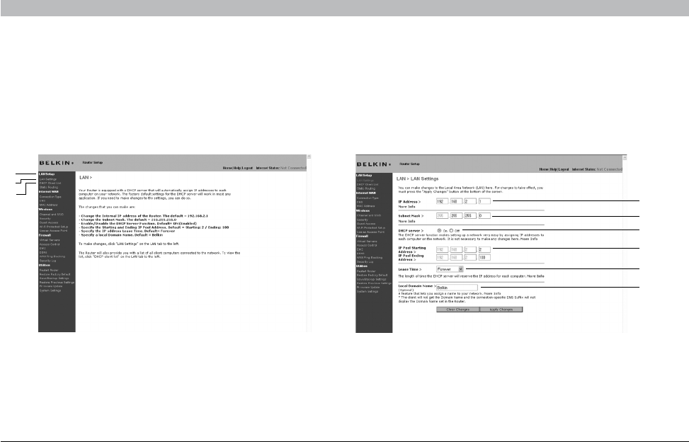
Viewing the LAN Settings
Clicking on the header of the LAN tab (1) will take you to the LAN tab’s
header page. A quick description of the functions can be found here. To
view the settings or make changes to any of the LAN settings, click on
“LAN Settings” (2) or to view the list of connected computers, click on
“DHCP client list” (3).
Changing LAN Settings
All settings for the internal LAN setup of the Router can be viewed and
changed here.
(1)
(2)
(3) (1)
(2)
(3)
(4)
(5)
(6)

36
N+ Wireless Router
SECTIONSTable of Contents 12345 789106
USING THE WEB-BASED ADVANCED USER INTERFACE
1. IP Address
The “IP address” is the internal IP address of the Router. The default IP
address is “192.168.2.1”. To access the advanced setup interface, type
this IP address into the address bar of your browser. This address can
be changed if needed. To change the IP address, type in the new IP
address and click “Apply Changes”. The IP address you choose should
be a non-routable IP. Examples of a non-routable IP are:
192.168.x.x (where x is anything between 0 and 255)
10.x.x.x (where x is anything between 0 and 255)
2. Subnet Mask
There is no need to change the subnet mask. This is a unique, advanced
feature of your Belkin Router. It is possible to change the subnet mask
if necessary; however, do NOT make changes to the subnet mask
unless you have a specific reason to do so. The default setting is
“255.255.255.0”.
3. DHCP Server
The DHCP server function makes setting up a network very easy by
assigning IP addresses to each computer on the network automatically.
The default setting is “On”. The DHCP server can be turned OFF if
necessary; however, in order to do so you must manually set a static
IP address for each computer on your network. To turn off the DHCP
server, select “Off” and click “Apply Changes”.
4. IP Pool
The range of IP addresses set aside for dynamic assignment to the
computers on your network. The default is 2–100 (99 computers). If you
want to change this number, you can do so by entering a new starting
and ending IP address and clicking on “Apply Changes”. The DHCP
server can assign 100 IP addresses automatically. This means that
you cannot specify an IP address pool larger than 100 computers. For
example, starting at 50 means you have to end at 150 or lower so as not
to exceed the 100-client limit. The starting IP address must be lower in
number than the ending IP address.
5. Lease Time
The length of time the DHCP server will reserve the IP address for each
computer. We recommend that you leave the lease time set to “Forever”.
The default setting is “Forever”, meaning that any time a computer is
assigned an IP address by the DHCP server, the IP address will not
change for that particular computer. Setting lease times for shorter
intervals such as one day or one hour frees IP addresses after the
specified period of time. This also means that a particular computer’s
IP address may change over time. If you have set any of the other
advanced features of the Router such as DMZ or client IP filters, these
are dependent on the IP address. For this reason, you will not want the
IP address to change.
6. Local Domain Name
The default setting is “Belkin”. You can set a local domain name
(network name) for your network. There is no need to change this setting
unless you have a specific advanced need to do so. You can name the
network anything you want such as “MY NETWORK”.
37
N+ Wireless Router
SECTIONSTable of Contents 12345 789106
USING THE WEB-BASED ADVANCED USER INTERFACE
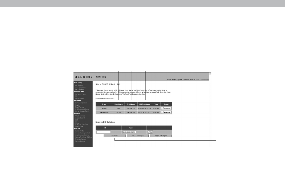
Viewing the DHCP Client List Page
You can view a list of the computers (known as clients), which are connected to your network. You are able to view the IP address (1) of the computer,
the host name (2) (if the computer has been assigned one), and the MAC address (3) of the computer’s network interface card (NIC). Pressing the
“Reserve” button will tie up the assigned IP address to the current MAC address. The “Reserved IP Database” section will show the linked IP and
MAC addresses. Pressing the “Refresh” (4) button will update the list. If there have been any changes, the list will be updated.
The “Network Address” section defines the local IP address or range. The “Subnet Mask and Gateway” section defines the mask and gateway for the
addresses above.
(1)(2) (3)
(4)
38
N+ Wireless Router
SECTIONSTable of Contents 12345 789106
USING THE WEB-BASED ADVANCED USER INTERFACE
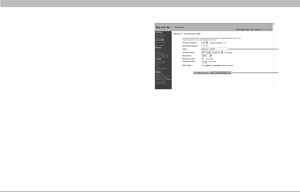
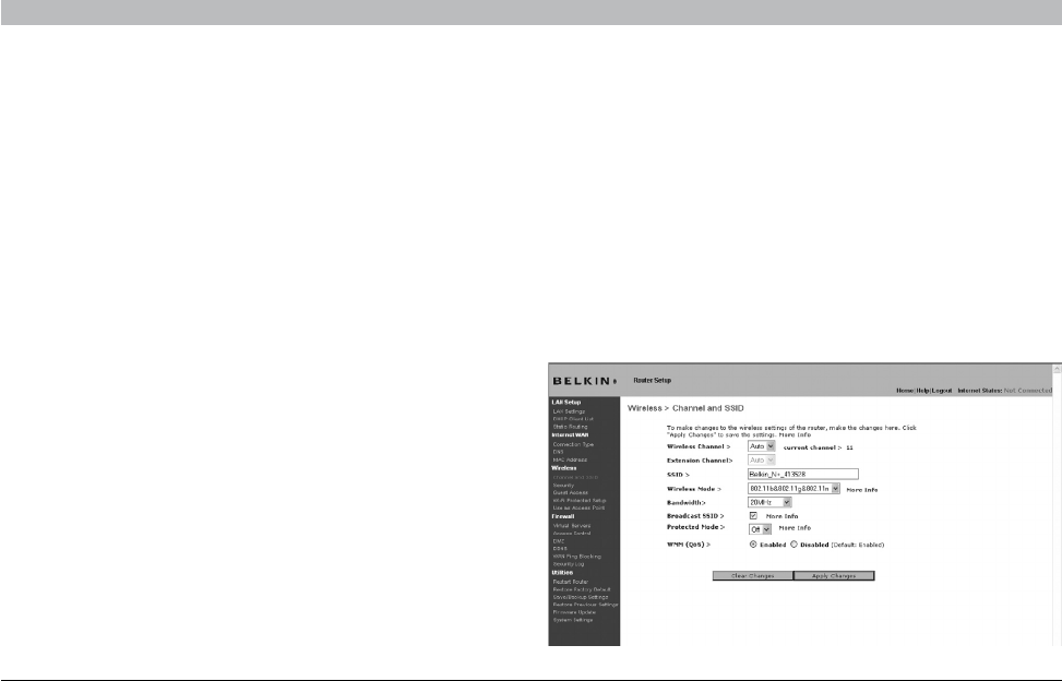
Configuring the Wireless Network Settings
The “Wireless” tab lets you make changes to the wireless network
settings. From this tab you can make changes to the wireless network
name or Service Set Identifier (SSID), operating channel, encryption
security settings, and configure the Router to be used as an access
point.
Changing the Wireless Network Name (SSID)
To identify your wireless network, a name called the SSID is used.
The SSID is your network name. The default network name of the
Router is “Belkin N+ Wireless” followed by six digits that are unique
to your Router. Your network name will look something like “Belkin_
N+_Wireless_123456”. You can change this to anything you choose,
or you can leave it unchanged. Keep in mind, if you decide to change
your wireless network name, and there are other wireless networks
operating in your area, your network name needs to be different from
other wireless networks that may be operating in your area. To change
the SSID, type in the SSID that you want to use in the SSID field (1)
and click “Apply Changes” (2). The change is immediate. If you make a
change to the SSID, your wireless-equipped computers may also need
to be reconfigured to connect to your new network name. Refer to the
documentation of your wireless network adapter for information on
making this change.
Note: Please periodically check for new Router firmware updates
from the “Utilities > Firmware update” page. Newer firmware can fix
problems, add wireless features, and/or improve wireless performance
(see page 57)
(1)
(2)
39
N+ Wireless Router
SECTIONSTable of Contents 12345 789106
USING THE WEB-BASED ADVANCED USER INTERFACE
Changing the Wireless Channel
There are a number of operating channels from which you can choose—
in the United States, there are 11 and in the United Kingdom (and most
of Europe), there are 13. In a small number of other countries, there are
other channel requirements. Your Router is configured to operate on the
proper channels for the country in which you reside. The channel can
be changed if needed. If there are other wireless networks operating in
your area, your network should be set to operate on a channel that is
different than the other wireless networks.
Extension Channel
The IEEE 802.11n draft specification allows the use of a secondary
channel to double the bandwidth (see “Using the Bandwidth Switch”
below). An appropriate extension channel will be displayed when
operating in 40MHz mode (see “Using the Wireless Mode Switch”
below). The channel can be changed if needed.
Using the Wireless Mode Switch
This switch allows you to set the Router’s wireless modes. There are
several modes.
Note: Some modes may require firmware updates to be enabled.
1. Off
This mode will turn OFF the Router’s access point, so no wireless
devices can join the network. Turning off the wireless function of your
Router is a great way to secure your network when you are away from
home for a long period of time, or don’t want to use the wireless feature
of the Router at a certain time.
2. 802.11b+g
Setting the Router to this mode will allow only 802.11b- and g-compliant
devices to join the network
3. 802.11b+g+n
Setting the Router to this mode will allow 802.11b-, 802.11g-, and
802.11n-compliant devices to join the network.
4. 802.11n only
Setting the Router to this mode will allow only N/draft 802.11n-compliant
devices to join the network, keeping out 802.11g and 802.11b devices.

40
N+ Wireless Router
SECTIONSTable of Contents 12345 789106
USING THE WEB-BASED ADVANCED USER INTERFACE
Using the Bandwidth Switch
This switch allows you to set the Router’s wireless bandwidth modes.
There are several modes available:
1. 20MHz only
Setting the Router to this mode allows only 20MHz operation. This mode
is compatible with N, draft 802.11n-, 802.11g-, and 802.11b-compliant
devices, but will limit N, draft 802.11n-compliant devices’ bandwidth by
half. Reducing bandwidth to 20MHz-only operation might solve some
wireless problems.
2) 20MHz/40MHz Auto
Setting the Router to this mode allows it to switch automatically between
20MHz and 40MHz operation. This mode enables 40MHz operation, to
maximize speed for N, draft 802.11n-compliant devices when conditions
permit. When a legacy 802.11g access point is presented and occupies
an adjacent secondary channel, the Router automatically reverts to
20MHz operation to maximize compatibility. We recommend using this
as the default mode.
Using the Broadcast SSID Feature
Note: This advanced feature should be employed by advanced users
only. For security, you can choose not to broadcast your network’s
SSID. Doing so will keep your network name hidden from computers
that are scanning for the presence of wireless networks. To turn off
the broadcast of the SSID, remove the check mark from the box next
to “Broadcast SSID”, and then click “Apply Changes”. The change is
immediate. Each computer now needs to be set to connect to your
specific SSID; an SSID of “ANY” will no longer be accepted. Refer to
the documentation of your wireless network adapter for information on
making this change.
Protected Mode Switch
Protected mode ensures proper operation of N, draft 802.11n-compliant
devices on your wireless network when 802.11g or 802.11b devices
are present or when there is heavy 802.11g or 802.11b traffic in the
operating environment. Use protected mode if your network consists of
a mix of Belkin N+ Wireless Cards and 802.11g or 802.11b cards on your
network. If you are in an environment that includes little to no 802.11g or
802.11b wireless network traffic, you will achieve the best N+ wireless
performance with protected mode OFF. Conversely, in an environment
with HEAVY 802.11g or 802.11b traffic or interference, you will achieve
the best N+ wireless performance with protected mode ON. This will
ensure N+ wireless performance is not affected.
802.11e/WMM (Wi-Fi® Multimedia) QoS
WMM, based on 802.11e QoS (Quality of Service), prioritizes important
data on your network, such as multimedia content and voice-over-IP
(VoIP), so it will not be interfered with by other data being sent over the
network. This feature requires other wireless devices, such as Wi-Fi
phones or wireless laptops, to support WMM for best results.
41
N+ Wireless Router
SECTIONSTable of Contents 12345 789106
USING THE WEB-BASED ADVANCED USER INTERFACE
Changing the Wireless Security Settings
Your N+ Wireless Router is equipped with the latest security standard
called Wi-Fi Protected Access™ 2 (WPA2™) and the legacy security
standard called Wired Equivalent Privacy (WEP). Your Router also
supports the Wi-Fi Protected Setup™ (WPS) specification, which
simplifies the setup of a wireless network. WPS uses familiar
methodologies, such as typing in a Personal Identification Number (PIN)
or pushing a button, to enable users to automatically configure network
names and strong WPA™/WPA2 data encryption and authentication. By
default, wireless security is disabled. To enable security, you will need
to determine which standard you want to use. To access the security
settings, click “Security” on the “Wireless” tab.
Using Wi-Fi Protected Setup
WPS uses WPA2 (described on page 42) for encryption. It does not
provide additional security, but rather, standardizes the method for
securing your wireless network. You may use either the Push Button
Configuration (PBC) method or PIN method to allow a device access to
your wireless network. Conceptually, the two methods work as follows:
PBC: First, initiate the WPS PBC procedure on the client device. Refer to
your client’s documentation on this procedure. Then, within two minutes,
push and hold the WPS button located on the front of your Router for
two seconds. Pushing the PBC button will automatically enable WPS.
The client has now been securely added to your wireless network.
PIN: The client device has an 8-digit PIN number that is associated
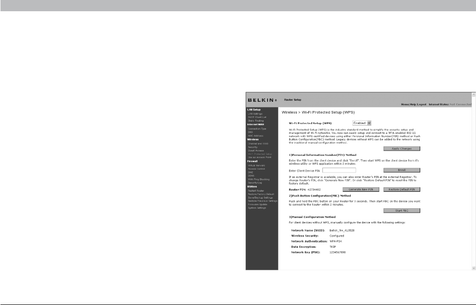
with WPS. Enable WPS through the screen illustrated below. Enter
the client’s PIN into the Router’s internal registrar (accessed through
this screen). The client will be automatically enrolled into your wireless
network within two minutes.

42
N+ Wireless Router
SECTIONSTable of Contents 12345 789106
USING THE WEB-BASED ADVANCED USER INTERFACE
1. Wi-Fi Protected Setup (WPS)
Enabled or Disabled.
2. Personal Identification Number (PIN) Method:
In this method, a wireless client wishing to access your network must
supply an 8-digit PIN to the Router. After clicking “Enroll”, you must start
the WPS handshaking procedure from the client within two minutes.
3. Router PIN
If an external registrar is available, you may enter in the Router’s PIN
to the registrar. Click “Generate New PIN” to change the PIN from the
default value. Click “Restore Default PIN” to reset the PIN value.
4. Push Button Configuration (PBC) Method
PBC is an alternate method to connect to a WPS network. Push the PBC
button located on the back of the Router for two seconds, and then
initiate the PBC on the client device. Alternatively, push the “Start PBC”
soft button to start this process.
5. Manual Configuration Method
This section lists the default security settings to be set up if not using
WPS.
WPA2 Requirements
IMPORTANT: In order to use WPA2 security, all your computers and
wireless client adapters must be upgraded with patches, driver, and
client utility software that supported WPA2. At the time of this User
Manual’s publication, a couple security patches are available, for free
download, from Microsoft®. These patches work only with the Windows
XP operating system. Other operating systems are not supported at this
time.
For Windows XP computers that do not have Service Pack 2 (SP2),
a file from Microsoft called “Windows XP Support Patch for Wireless
Protected Access (KB 826942)” is available for free download at
http://support.microsoft.com/kb/826942
For Windows XP with Service Pack 2, Microsoft has released a
free download to update the wireless client components to support
WPA2 (KB971021). The update is available from: http://support.
microsoft.com/kb/917021
These steps are not necessary for Windows XP SP3 and above.
IMPORTANT: You also need to ensure that all your wireless client cards/
adapters support WPA2, and that you have downloaded and installed
the latest driver. Most of the Belkin wireless cards have driver updates
available for download from the Belkin support site: www.belkin.com/
networking.
43
N+ Wireless Router
SECTIONSTable of Contents 12345 789106
USING THE WEB-BASED ADVANCED USER INTERFACE
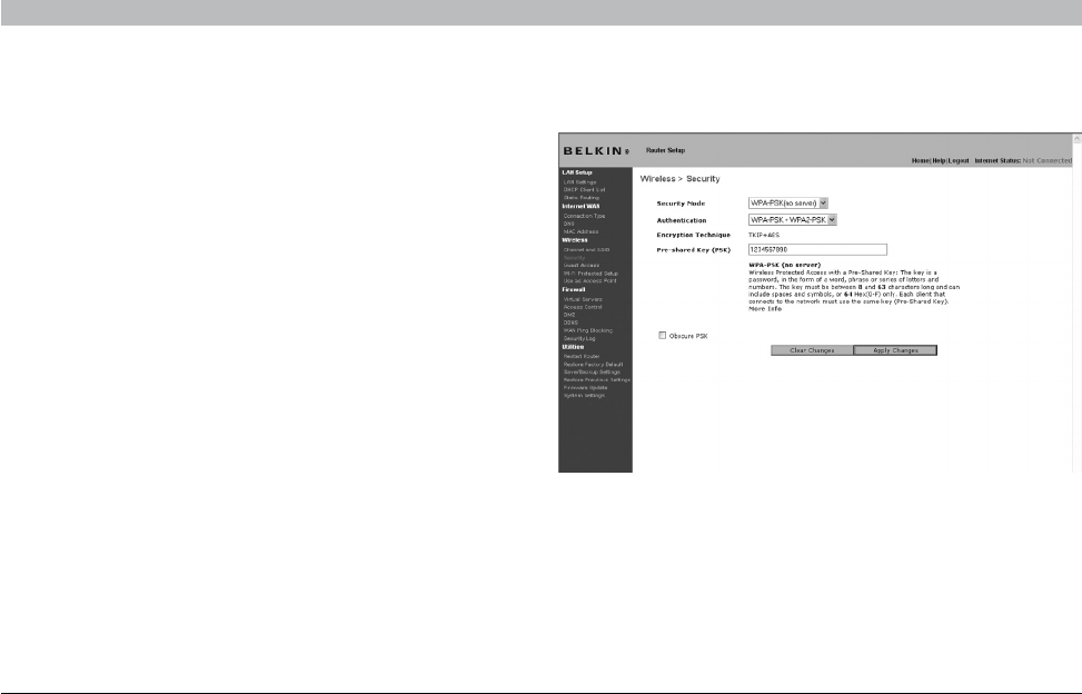
Setting WPA/WPA2-Personal (PSK)
Like WPA security, WPA2 is available in both WPA2-Personal (PSK)
mode and WPA2-Enterprise (RADIUS) mode. Typically, WPA2-Personal
(PSK) is the mode that will be used in a home environment, while WPA2-
Enterprise (RADIUS) is implemented in a business environment where
an external radius server distributes the network key to the clients
automatically. Your Router supports WPA2-Personal (PSK).
1. After you’ve set up your Router, go to the “Security” page under
“Wireless” and select “WPA-PSK(no server)” from the “Security Mode”
drop-down menu.
2. For “Authentication”, select “WPA-PSK”, “WPA2-PSK”, or “WPA-
PSK + WPA2-PSK”. This setting will have to be identical on the wireless
clients that you set up. “WPA-PSK + WPA2-PSK” mode will allow the
Router to support clients running either WPA or WPA2 security.
3. For “Encryption Technique” will auto-fill depending on the
authentication type above. This setting will have to be identical on the
wireless clients that you set up.
4. Enter your pre-shared key (PSK). This can be from eight to 63
characters and can be letters, numbers, or symbols. This same key must
be used on all of the wireless clients that you set up. For example, your
PSK might be something like: “Smith family network key”. Click “Apply
Changes” to finish. You must now set all wireless clients to match these
settings. IMPORTANT: Make sure your wireless computers are updated to work
with WPA2 and have the correct settings to get proper connection to the
Router.
44
N+ Wireless Router
SECTIONSTable of Contents 12345 789106
USING THE WEB-BASED ADVANCED USER INTERFACE
Setting WEP Encryption
Note to Mac users: The “Passphrase” option will not operate with
Apple® AirPort®. To configure encryption for your Mac computer, set
the encryption using the manual method described in the next section.
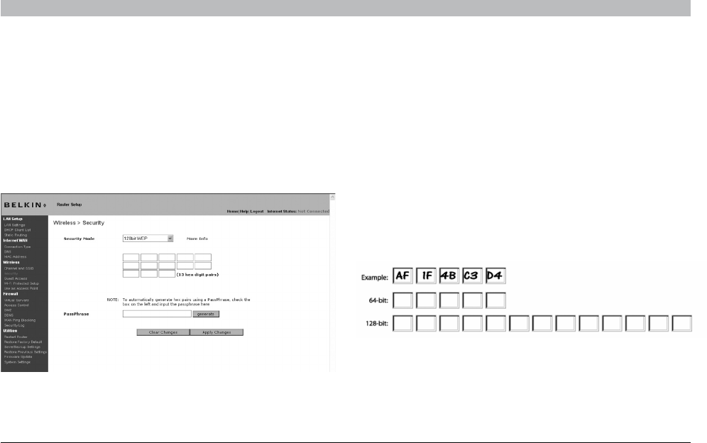
1. Select “128-bit WEP” or “64-bit WEP” from the drop-down menu.
2. After selecting your WEP encryption mode, you can enter you WEP
key manually by typing in the hex WEP key manually, or you can
type a passphrase in the “PassPhrase” field and click “Generate” to
create a WEP key from the passphrase. Click “Apply Changes” to
finish. You must now set all of your clients to match these settings.
Using a Hexadecimal Key
A hexadecimal key is a mixture of numbers and letters from A–F and
0–9. 64-bit keys are 10 digits long and can be divided into five two-digit
numbers. 128-bit keys are 26 digits long and can be divided into 13 two-
digit numbers.
For instance:
AF 0F 4B C3 D4 = 64-bit key
C3 03 0F AF 0F 4B B2 C3 D4 4B C3 D4 E7 = 128-bit key
In the boxes below, make up your key by writing in two characters
between A–F and 0–9. You will use this key to program the encryption
settings on your Router and your wireless computers.
Note to Mac users: Original Apple AirPort products support 64-bit
encryption only. Apple AirPort 2 products can support 64-bit or 128-bit
encryption. Please check your product to see which version you are
using. If you cannot configure your network with 128-bit encryption, try
64-bit encryption.
3. Encryption in the Router is now set. Each of your computers on
your wireless network will now need to be configured with the same
passphrase. Refer to the documentation of your wireless network
adapter for information on making this change.
45
N+ Wireless Router
SECTIONSTable of Contents 12345 789106
USING THE WEB-BASED ADVANCED USER INTERFACE
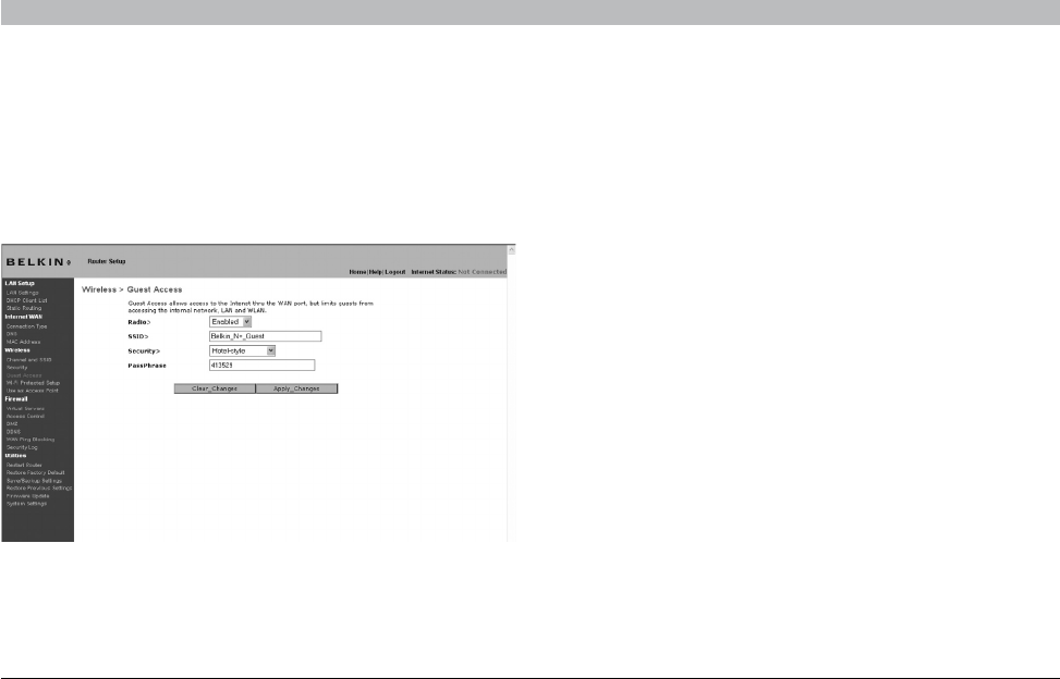
Guest Access: This option allows guest users access to the Internet
while keeping them away from your private network. By default, this
option is enabled. Guest users should connect to the Belkin N+ Guest
network.
Security options for Guest Access:
Hotel Style: Users will be redirected to a hotel-style landing page when
they first try to access the Internet. They must correctly enter in the
passphrase to log in.
WPA/WPA2-PSK: This option is similar to the security mode for the main
router network. Users must correctly enter the PSK in order to join the
guest network.
46
N+ Wireless Router
SECTIONSTable of Contents 12345 789106
USING THE WEB-BASED ADVANCED USER INTERFACE
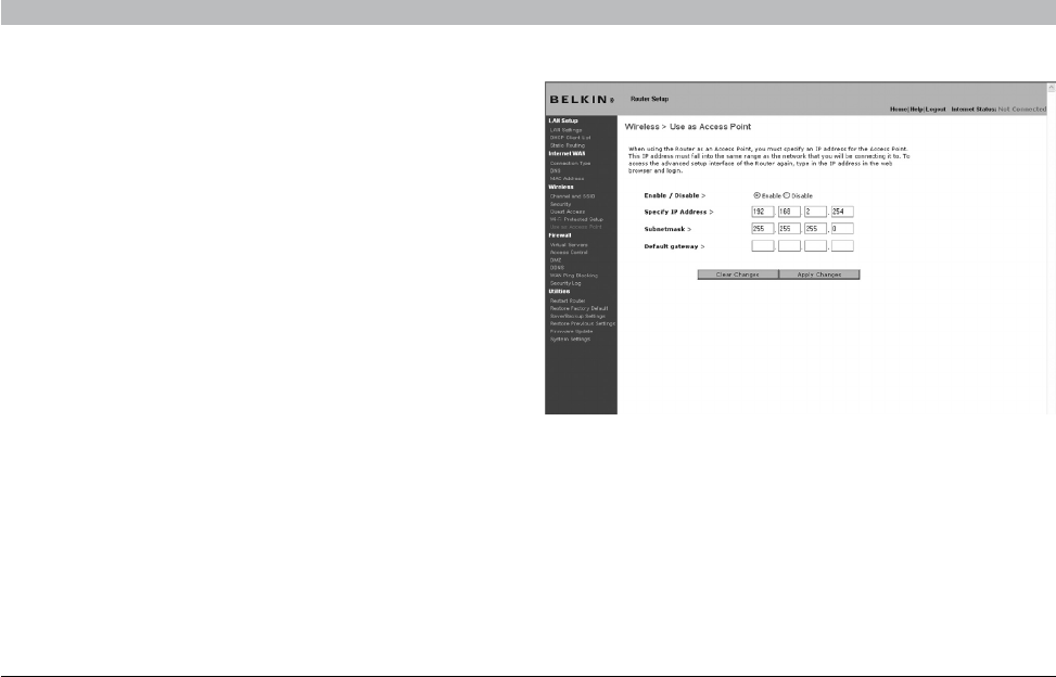
Using the Access Point Mode
Note: This advanced feature should be employed by advanced users
only. The Router can be configured to work as a wireless network
access point. Using this mode will defeat the NAT IP sharing feature and
DHCP server. In AP mode, the Router will need to be configured with an
IP address that is in the same subnet as the rest of the network that you
will bridge to. The default IP address is 192.168.2.254 and subnet mask
is 255.255.255.0. These can be customized for your need.
1. Enable the AP mode my selecting “Enable” in the “Use as Access
Point only” page. When you select this option, you will be able to
change the IP settings.
2. Set your IP settings to match your network. Click “Apply Changes”.
3. Connect a cable from the WAN port on the Router to your existing
network.
The Router is now acting as an access point. To access the Router
advanced user interface again, type the IP address you specified into
your browser’s navigation bar. You can set the encryption settings, MAC
address filtering, SSID, and channel normally.
47
N+ Wireless Router
SECTIONSTable of Contents 12345 789106
USING THE WEB-BASED ADVANCED USER INTERFACE
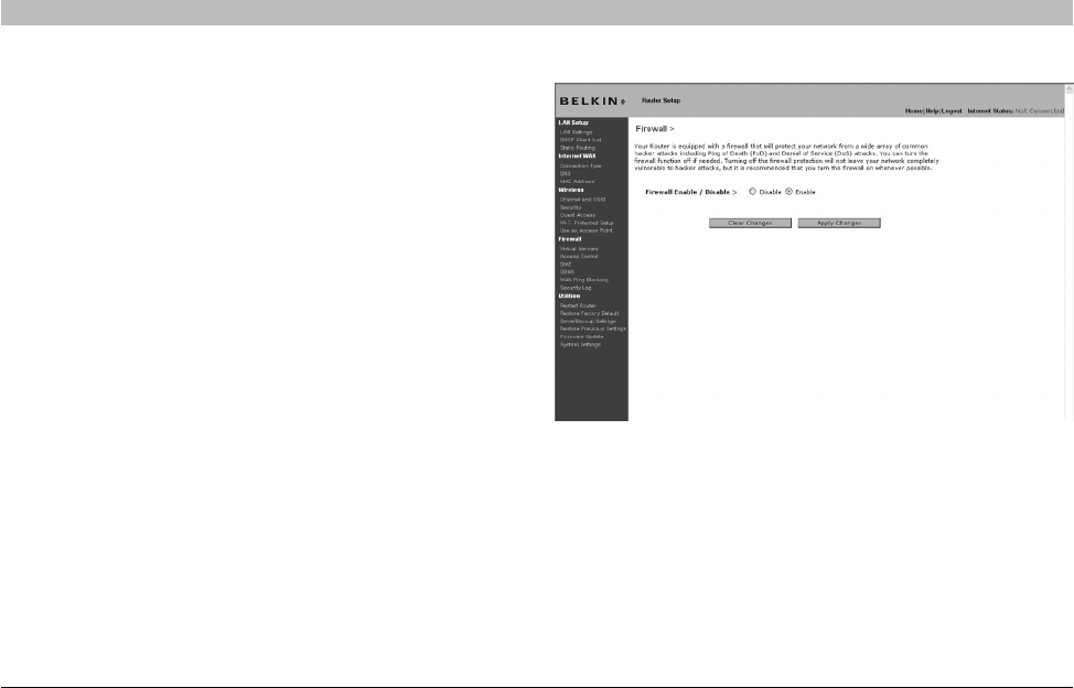
Configuring the Firewall
Your Router is equipped with a firewall that will protect your network
from a wide array of common hacker attacks including:
• IPSpoofing
• LandAttackPingofDeath(PoD)
• DenialofService(DoS)
• IPwithzerolength
• SmurfAttack
• TCPNullScan
• SYNflood
• UDPflooding
• TearDropAttack
• ICMPdefect
• RIPdefect
• Fragmentflooding
The firewall also masks common ports that are frequently used to
attack networks. These ports appear to be “stealth” meaning that for
all intents and purposes, they do not exist to a would-be hacker. You
can turn the firewall function off if needed; however, it is recommended
that you leave the firewall enabled. Disabling the firewall protection will
not leave your network completely vulnerable to hacker attacks, but it is
recommended that you leave the firewall enabled.
48
N+ Wireless Router
SECTIONSTable of Contents 12345 789106
USING THE WEB-BASED ADVANCED USER INTERFACE
Configuring Internal Forwarding Settings
The Virtual Servers function will allow you to route external (Internet)
calls for services such as a web server (port 80), FTP server (Port 21), or
other applications through your Router to your internal network. Since
your internal computers are protected by a firewall, computers outside
your network (over the Internet) cannot get to them because they cannot
be “seen”. A list of common applications has been provided in case you
need to configure the Virtual Server function for a specific application.
If your application is not listed, you will need to contact the application
vendor to find out which port settings you need.
Choosing an Application
Select your application from the drop-down list. Click “Add”. The
settings will be transferred to the next available space in the screen.
Click “Apply Changes” to save the setting for that application. To remove
an application, select the number of the row that you want to remove
then click “Clear”.
Manually Entering Settings into the Virtual Server
To manually enter settings, enter the IP address in the space provided
for the internal (server) machine, the port(s) required to pass (use a
comma between multiple ports), select the port type (TCP or UDP),
and click “Apply Changes”. You can only pass one port per internal IP
address. Opening ports in your firewall can pose a security risk. You can
enable and disable settings very quickly. It is recommended that you
disable the settings when you are not using a specific application.
49
N+ Wireless Router
SECTIONSTable of Contents 12345 789106
USING THE WEB-BASED ADVANCED USER INTERFACE
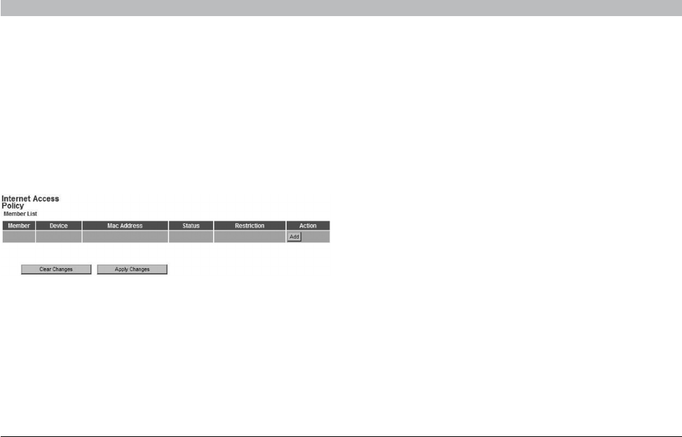
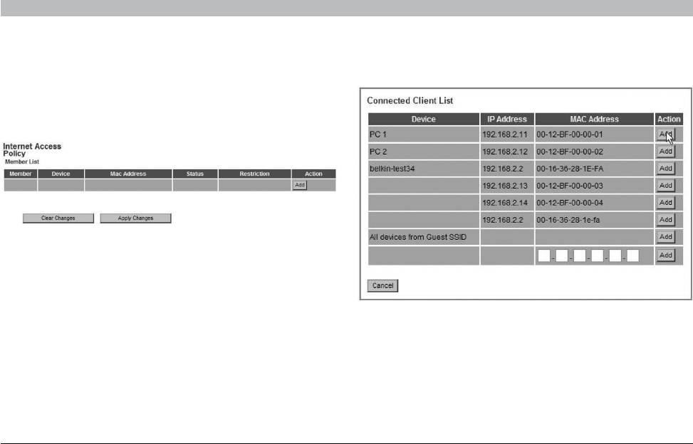
Access Control
The Router can be configured to restrict access to the Internet, email,
or other network services at specific days and times. Restriction can be
set for a single computer, a range of computers, or multiple computers.
Select the “Enable” radio button to use this feature.
To restrict Internet access to a single computer, for example, click the
“Add” button and select the appropriate entry. This entry will deny
access as a default according the specified criteria. Users can also add
a particular MAC address of a device manually and press the “Add”
button. They can also create a blanket rule for all the devices that are
connecting via the Guest Access feature.
50
N+ Wireless Router
SECTIONSTable of Contents 12345 789106
USING THE WEB-BASED ADVANCED USER INTERFACE
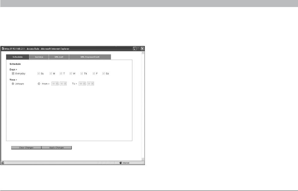
The Access Control rule can be removed by clicking the “Delete” button.
Click on the entry number for the configuration options.
There are four main configurations for Access Control lists. The first one
is “Schedule” for that rule. The second is “Service” for the services to
be blocked for that rule. The third is “URL Blocking” for the URL access
restrictions, and the fourth is “URL Keyword Blocking” for certain
keywords to be blocked in the URL address.
“Everyday” is the default for the days of the week that this rule will be
implemented on the “Schedule” page.
The second configuration for the Access Control list is the “service” that
is to be blocked or allowed. Users can choose to “Block All Services”,
“Allow All Services”, or configure from a list of predefined popular
services.
The third configuration for the Access Control list is the “URL List” for
the URL addresses that are to be blocked or allowed. Users can choose
to “Block All URLs”, “Allow All URLs”, or configure their own list of URLs.
The fourth configuration for the Access Control list is the “URL Keyword
List” for the URL address keywords that are to be blocked or allowed.
The default value is blank for this list and the user can configure a list of
URL address keywords.
51
N+ Wireless Router
SECTIONSTable of Contents 12345 789106
USING THE WEB-BASED ADVANCED USER INTERFACE
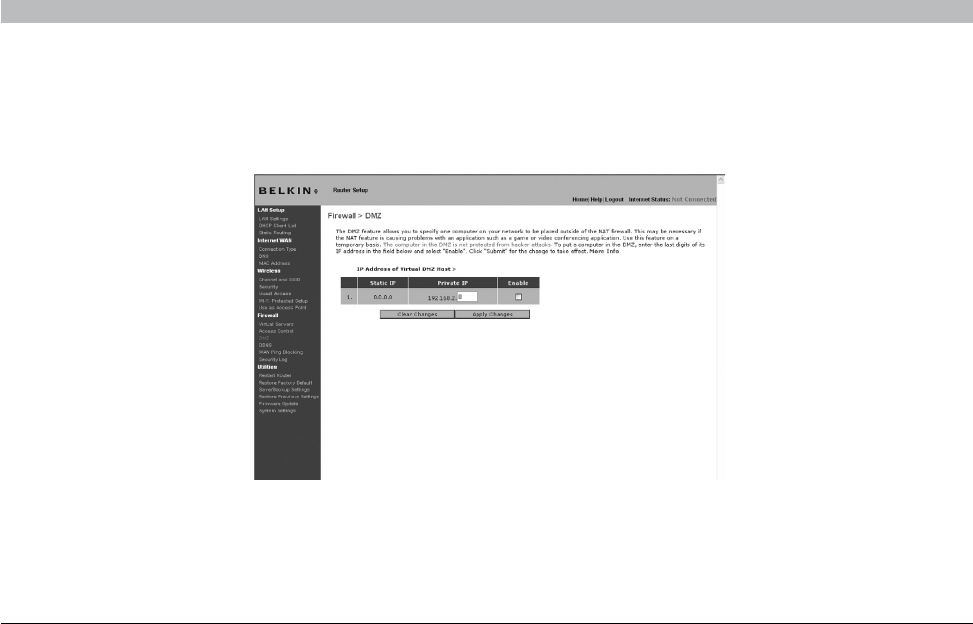
Enabling the Demilitarized Zone (DMZ)
The DMZ feature allows you to specify one computer on your network to be placed outside of the firewall. This may be necessary if the firewall is
causing problems with an application such as a game or video conferencing application. Use this feature on a temporary basis. The computer in the
DMZ is NOT protected from hacker attacks.
To put a computer in the DMZ, enter the last digits of its IP address in the IP field and select “Enable”. Click “Apply Changes” for the change to take
effect. If you are using multiple static WAN IP addresses, it is possible to select which WAN IP address the DMZ host will be directed to. Type in the
WAN IP address you wish the DMZ host to direct to, enter the last two digits of the IP address of the DMZ host computer, select “Enable” and click
“Apply Changes”.
52
N+ Wireless Router
SECTIONSTable of Contents 12345 789106
USING THE WEB-BASED ADVANCED USER INTERFACE
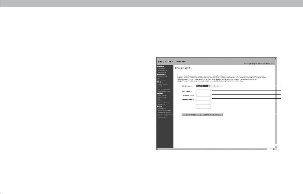
Using Dynamic DNS
The Dynamic DNS service allows you to alias a dynamic IP address
to a static host name in any of the many domains DynDNS.org offers,
allowing your network computers to be more easily accessed from
various locations on the Internet. DynDNS.org provides this service, for
up to five host names, free to the Internet community.
The Dynamic DNSSM service is ideal for a home website, file server, or
to make it easy to access your home PC and stored files while you’re at
work. Using the service can ensure that your host name always points to
your IP address, no matter how often your ISP changes it. When your IP
address changes, your friends and associates can always locate you by
visiting yourname.dyndns.org instead!
To register free for your Dynamic DNS host name, please visit http://
www.dyndns.org.
Setting up the Router’s Dynamic DNS Update Client
You must register with DynDNS.org’s free update service before using
this feature. Once you have your registration, follow the directions below.
1. Select DynDNS as the “DDNS Service” (1).
2. Enter your DynDNS.org user name in the “User Name” field (2).
3. Enter your DynDNS.org password in the “Password” field (3).
4. Enter the DynDNS.org domain name you set up with DynDNS.org in
the “Domain Name” field (4).
5. Click “Update Dynamic DNS” (5) to update your IP address.
Whenever your IP address assigned by your ISP changes, the Router will
automatically update DynDNS.org’s servers with your new IP address.
You can also do this manually by clicking the “Update Dynamic DNS”
button (5).
(1)
(2)
(3)
(4)
(5)
53
N+ Wireless Router
SECTIONSTable of Contents 12345 789106
USING THE WEB-BASED ADVANCED USER INTERFACE
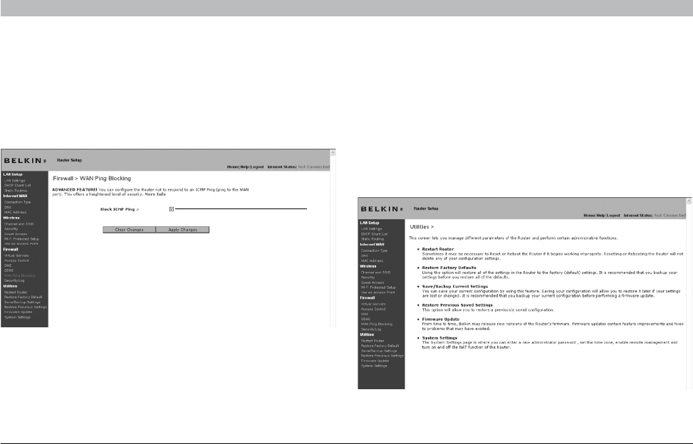
Blocking an ICMP Ping
Computer hackers use what is known as “pinging” to find potential
victims on the Internet. By pinging a specific IP address and receiving a
response from the IP address, a hacker can determine that something of
interest might be there. The Router can be set up so it will not respond
to an ICMP ping from the outside. This heightens your Router’s security
level.
To turn off the ping response, select “Block ICMP Ping” (1) and click
“Apply Changes”. The Router will not respond to an ICMP ping.
Security Log
This page keeps a log of router activity, such as computers logging in to
and out of the Router, as well as attempts from the Internet to connect
to the Router. This log file can be saved and cleared.
Utilities
The “Utilities” screen lets you manage different parameters of the Router
and perform certain administrative functions.
(1)
54
N+ Wireless Router
SECTIONSTable of Contents 12345 789106
USING THE WEB-BASED ADVANCED USER INTERFACE
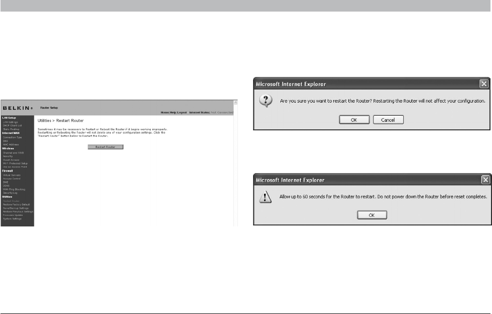
Restarting the Router
Sometimes it may be necessary to restart or reboot the Router if it
begins working improperly. Restarting or rebooting the Router will NOT
delete any of your configuration settings.
Restarting the Router to Restore Normal Operation
1. Click the “Restart Router” button.
2. The following message will appear. Click “OK”.
3. The following message will appear. Restarting the Router can take
up to 60 seconds. It is important not to turn off the power to the
Router during the restart.
4. A 60-second countdown will appear on the screen. When the
countdown reaches zero, the Router will be restarted. The Router
home page should appear automatically. If not, type in the Router’s
address (default = 192.168.2.1) into the navigation bar of your
browser.
55
N+ Wireless Router
SECTIONSTable of Contents 12345 789106
USING THE WEB-BASED ADVANCED USER INTERFACE
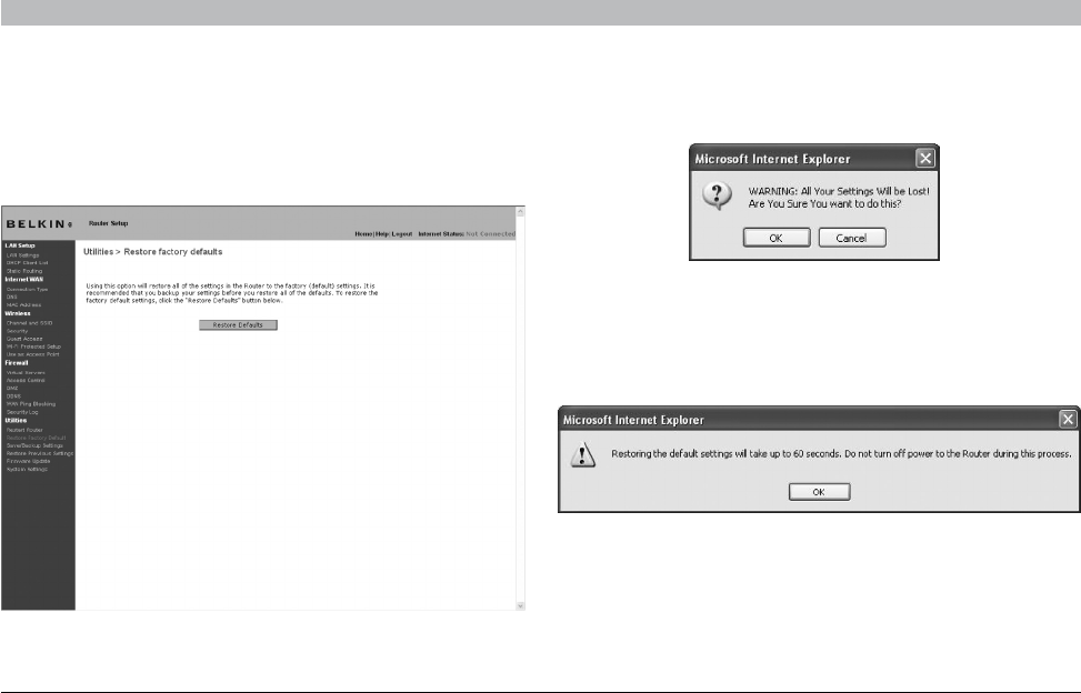
Restoring Factory Default Settings
Using this option will restore all of the settings in the Router to the
factory (default) settings. It is recommended that you back up your
settings before you restore all of the defaults.
1. Click the “Restore Defaults” button.
2. The following message will appear. Click “OK”.
3. The following message will appear. Restoring the defaults includes
restarting the Router. It can take up to 60 seconds. It is important
not to turn the power to the Router off during the restart.
4. A 60-second countdown will appear on the screen. When the
countdown reaches zero, the Router’s defaults will be restored. The
Router home page should appear automatically. If it does not, type
in the Router’s address (default = 192.168.2.1) into the navigation bar
of your browser.
56
N+ Wireless Router
SECTIONSTable of Contents 12345 789106
USING THE WEB-BASED ADVANCED USER INTERFACE
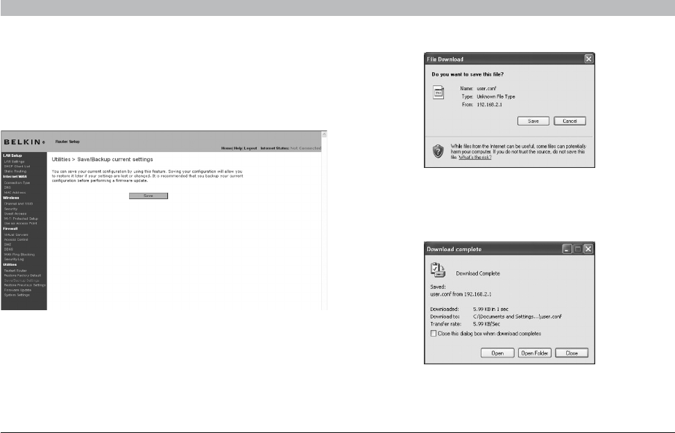
Saving a Current Configuration
You can save your current configuration by using this feature. Saving
your configuration will allow you to restore it later if your settings are
lost or changed. It is recommended that you back up your current
configuration before performing a firmware update.
2. A window will open that allows you to select the location where you
want to save the configuration file. Select a location. You can name
the file anything you want, or use the default name “user.conf”. Be
sure to name the file so you can locate it yourself later. When you
have selected the location and name of the file, click “Save”.
3. When the save is complete, you will see the window below. Click
“Close”.
The configuration is now saved.
1. Click “Save”. A window called “File Download” will open. Click
“Save”.
57
N+ Wireless Router
SECTIONSTable of Contents 12345 789106
USING THE WEB-BASED ADVANCED USER INTERFACE
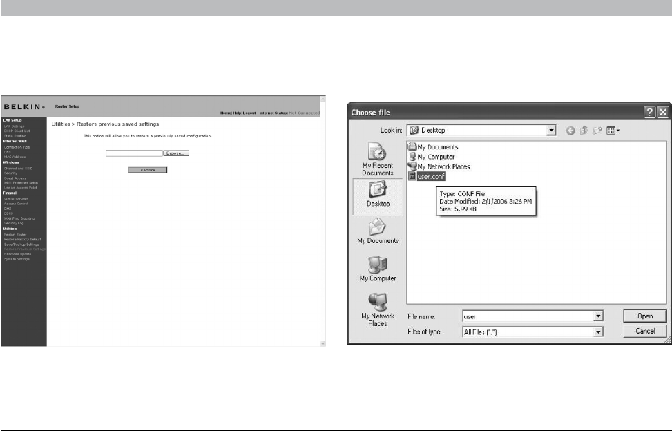
Restoring a Previous Configuration
This option will allow you to restore a previously saved configuration.
1. Click “Browse”. A window will open that allows you to select the
location of the configuration file. All configuration files end with a
“.conf”. Locate the configuration file you want to restore and double-
click on it.
58
N+ Wireless Router
SECTIONSTable of Contents 12345 789106
USING THE WEB-BASED ADVANCED USER INTERFACE
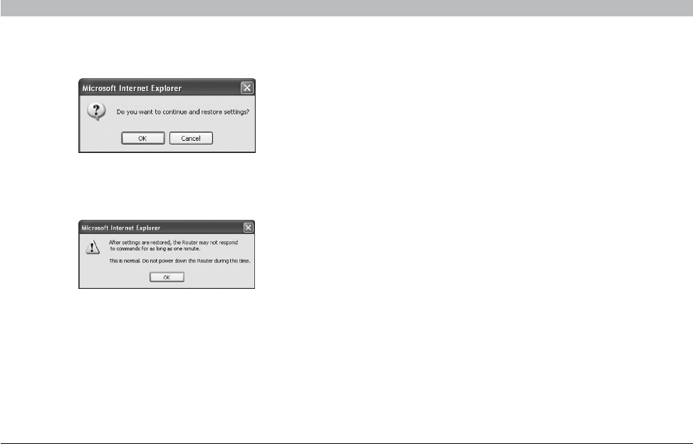
2. You will be asked if you want to continue. Click “OK”.
3. A reminder window will appear. It will take up to 60 seconds for the
configuration restoration to complete. Click “OK”.
4. A 60-second countdown will appear on the screen. When the
countdown reaches zero, the Router’s configuration will be restored.
The Router’s home page should appear automatically. If not, type in
the Router’s address (default = 192.168.2.1) into the navigation bar of
your browser.