Belkin F5D8235V3 N+ Wireless Router User Manual
Belkin International, Inc. N+ Wireless Router
UserManual.wiki
>
Belkin
>
F5D8235V3 User Manual
user Manual
Navigation menu
Upload a User Manual
Namespaces
Wiki Guide
HTML
PDF
Info
Views
User Manual
Discussion / Help
Navigation
![PM00736-A_F5D8235-4_N+_RTR_MNL_jdk.doc Page 8 of 120 The Setup Assistant, second generation of Belkin’s renowned Easy Install Wizard, takes the guesswork out of setting up your Router. This automatic software determines your network settings for you and sets up the Router for connection to your Internet Service Provider (ISP). In a matter of minutes, your Router will be up and running on the Internet. Note: Setup Assistant software is compatible with Windows 2000, XP, and Vista; and Mac OS X v10.x. If you are using another operating system, the Router can be set up using the Alternate Setup Method described in this User Manual (see page xx) [VERIFY PAGE NUMBER]. Integrated N+ Wireless Access Point N MIMO is an exciting new wireless technology based on the draft IEEE 802.11n specification. It employs MIMO (Multiple Input Multiple Output) smart-antenna technology that achieves data rates of up to 300Mbps.* Actual throughput is typically lower than the connected data rate and will vary depending on your networking environment. *NOTE: The standard transmission rate—300Mbps—is the physical data rate. Actual data throughput will be lower. MAC Address Filtering For added security, you can set up a list of MAC addresses (unique client identifiers) that are allowed access to your network. Every computer has its own MAC address. Simply enter these MAC addresses into a list using the Web-Based Advanced User Interface and you can control access to your network.](https://usermanual.wiki/Belkin/F5D8235V3/User-Guide-1160721-Page-8.png)
![PM00736-A_F5D8235-4_N+_RTR_MNL_jdk.doc Page 10 of 120 Knowing your Router The Router has been designed to be placed on a desktop. All of the cables exit from the rear of the Router for better organization and utility. The Network Status Display is easily visible on the FRONT of the Router to provide you with information about network activity and status. See the Network Status Display Guide for more detailed information. [Replace with “final” N+ Wireless Router Network Status Display line art with A to J line up with LEDs] [Note, Please update with F5D8235-4 V3 LED artwork, which has slightly different icons] A. Broadband Download Speedometer These lights will display a graphic representation of the current download speed being transferred through the Internet connection. The speed will be measured on the speedometer against the fastest speed that has been measured by the N+ since being activated. B. Wireless Security [insert Lock Icon] C. WPS Push Button (insert the security lock icon) This button is set aside for the Wi-Fi Protected Setup feature. Refer to the “Changing the Wireless Security Settings” section for more details. D. Wireless-Computer Status [insert Laptop Icon] Off Wireless computer is not present Solid Blue Wireless computer is connected to the Router Blinking Amber Problem with wireless computer connecting properly to the Router E. Wired-Computer Status [Computer Icon] Off Wired computer is not present Solid Blue Wired computer is connected to the Router Blinking Amber Problem with wired computer connecting properly to the Router F. USB Port Status [USB Icon] Off No device is plugged into the USB port Flashing Blue Data is being read/written to the storage device Flashing Amber Unsupported device is plugged into the USB port Off Wireless security is off Blinking Blue WPS handshaking in process Solid Blue Wireless security is on](https://usermanual.wiki/Belkin/F5D8235V3/User-Guide-1160721-Page-10.png)
![PM00736-A_F5D8235-4_N+_RTR_MNL_jdk.doc1 Page 11 of 120 Solid Blue Storage device is plugged in and ready to be accessed G. Router/Power Status [insert Router Icon] When you apply power to the Router or restart it, a short period of time elapses while the Router boots up. During this time, the “router” icon blinks. When the Router has completely booted up, the “router” icon becomes a solid light, indicating the Router is ready for use. Off Router is off Blinking Blue Router is booting up Solid Blue Router is on and ready H. Wireless Status [insert Wireless Wave Icon over the Router] Off Wireless is off Solid Blue Wireless is on I. Modem Status [insert modem Icon] This icon lights in blue to indicate that your Router is connected properly to the modem. It turns amber when a problem is detected. Off Router is NOT connected to modem Solid Blue Router is connected to modem and functioning properly Blinking Amber Problem with modem J. Internet Status [insert Globe Icon] This unique icon shows you when the Router is connected to the Internet. When the light is off, the Router is NOT connected to the Internet. When the light is blinking amber, the Router is attempting to connect to the Internet. When the light is solid blue, the Router is connected to the Internet. When using the “Disconnect after x minutes” feature, this icon becomes extremely useful in monitoring the status of your Router’s connection. Off Router is NOT connected to the Internet Blinking Blue Router is attempting to connect to the Internet Solid Blue Router is connected to the Internet Blinking Amber Problem with connecting to the Internet [insert “final” N+ Wireless Router rear-panel line art with K to O line up to the ports]](https://usermanual.wiki/Belkin/F5D8235V3/User-Guide-1160721-Page-11.png)
![PM00736-A_F5D8235-4_N+_RTR_MNL_jdk.doc1 Page 13 of 120 • Belkin N+ Wireless Router • RJ45 Ethernet Networking Cable • Power Supply • Belkin Setup Assistant Software CD • User Manual on the Setup Assistant CD • Network Status Display Guide • Wireless Security Setup Guide Modem Requirements Your cable or DSL modem must be equipped with an RJ45 Ethernet port. Many modems have both an RJ45 Ethernet port and a USB connection. If you have a modem with both Ethernet and USB, and are using the USB connection at this time, you will be instructed to use the RJ45 Ethernet port during the installation procedure. If your modem has only a USB port, you can request a different type of modem from your ISP, or you can, in some cases, purchase a modem that has an RJ45 Ethernet port on it. [use existing lineart] Setup Assistant Belkin has provided our Setup Assistant software to make installing your Router a simple and easy task. You can use it to get your Router up and running in minutes. The Setup Assistant requires that your computer be connected directly to your cable or DSL modem and that the Internet connection is active and working at the time of installation. If it is not, you must use the “Alternate Setup Method” section of this User Manual to configure your Router. Additionally, if you are using an operating system other than Windows 2000, XP, or Vista, or Mac OS X v10.x, you must set up the Router using the “Alternate Setup Method” section of this User Manual. [Please update from the final N+ QIG, PM00737] Step 1: Hardware Connections – Follow the Quick Installation Guide (QIG) [Insert line art from the QIG] 1. Find the cable connecting your modem and computer*. Unplug it from the computer and plug it into the yellow port on the Belkin Router. 2. Connect the new cable (provided in the box) to any gray port on the Router. Plug the other end into a network (Ethernet) port on your computer. Ethernet USB](https://usermanual.wiki/Belkin/F5D8235V3/User-Guide-1160721-Page-13.png)
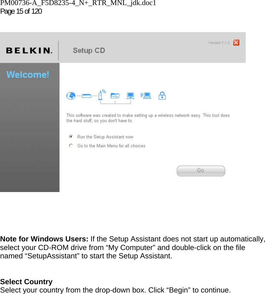
![PM00736-A_F5D8235-4_N+_RTR_MNL_jdk.doc Page 14 of 120 3. Plug the power supply into a wall outlet, and the other end into the black port on the Belkin Router. As the Router wakes up, lights will come on; recheck your connections if the “Wired” and “Router” lights are not a steady blue after 20 seconds. 4. Rotate the antennas up. 5. Locate the CD in this guide and insert it into your computer. The Setup Wizard should appear automatically. If it doesn’t, open the CD in My Computer (Windows) or the Finder (Mac OS X) and double-click the “Router Setup” icon. *If you are replacing an existing router, find the cable connecting the modem and old router. Disconnect it from the old router and plug it into the yellow port on the new router. Step 2: Set Up the Router – Run the Setup Assistant Software A. Shut down any programs that are running on your computer at this time. Turn off any firewall or Internet-connection-sharing software on your computer. B. Insert the CD into your computer. The Setup Assistant will automatically appear on your computer’s screen within 15 seconds. Click on “Go” to run the Setup Assistant. Follow the instructions there. [Keep existing screenshots for Step2] <Insert: EZI_1.tif> IMPORTANT: Run the Setup Assistant from the computer that is directly connected to the Router from Step 1 – B.](https://usermanual.wiki/Belkin/F5D8235V3/User-Guide-1160721-Page-14.png)
![PM00736-A_F5D8235-4_N+_RTR_MNL_jdk.doc Page 16 of 120 [Note from PM: Please modify the left hand menu in the following EZI screenshots below to match the left hand menu in the screen shot above.] Confirmation Screen Verify that you have completed all QIG steps by checking the box to the right of the arrow. Click “Next” to continue.](https://usermanual.wiki/Belkin/F5D8235V3/User-Guide-1160721-Page-16.png)
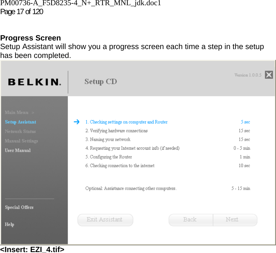
![PM00736-A_F5D8235-4_N+_RTR_MNL_jdk.doc Page 18 of 120 1.1 Checking Settings The Setup Assistant will now examine your computer’s network settings and gather information needed to complete the Router’s connection to the Internet. 1.2 Verifying Hardware Connections The Setup Assistant will now verify your hardware connection. [insert EZI_5.tif]](https://usermanual.wiki/Belkin/F5D8235V3/User-Guide-1160721-Page-18.png)
![PM00736-A_F5D8235-4_N+_RTR_MNL_jdk.doc1 Page 19 of 120 1.3 Naming your Wireless Network The Setup Assistant will display the default wireless network name or Service Set Identifier (SSID). This is the name of your wireless network to which your computers or devices with wireless network adapters will connect. You can either use the default or change it to something unique. Write down this name for future reference. Click “Next” to continue. [insert EZI_7.tif]](https://usermanual.wiki/Belkin/F5D8235V3/User-Guide-1160721-Page-19.png)
![PM00736-A_F5D8235-4_N+_RTR_MNL_jdk.doc Page 20 of 120 [in screenshot above, the “r” in router should be capitalized in “Belkin routers”] 1.4 Requesting Internet Account Info (if needed) If your Internet account requires a login and password, you will be prompted with a screen similar to the illustration below. Select your country or ISP from the drop-down boxes.](https://usermanual.wiki/Belkin/F5D8235V3/User-Guide-1160721-Page-20.png)
![PM00736-A_F5D8235-4_N+_RTR_MNL_jdk.doc1 Page 21 of 120 [insert EZI_9.tif] [text in screenshot above should say, “The Router needs a bit more information in order to be able to connect to the Internet. When you tell us who provides your service, we can configure most of it:”; also header should read “Internet account info”—note the sentence casing to remain consistent with the prev. headers] [insert EZI_9b.tif & EZI_9c.tif] 1.5 Configuring the Router The Setup Assistant will now configure your Router by sending data to the Router and restarting it. Wait for the on-screen instructions. Note: Do not disconnect any cable or power off the Router while the Router is rebooting. Doing so will render your Router inoperable.](https://usermanual.wiki/Belkin/F5D8235V3/User-Guide-1160721-Page-21.png)
![PM00736-A_F5D8235-4_N+_RTR_MNL_jdk.doc Page 22 of 120 [insert EZI_11.tif] 1.6 Checking Internet Connection We are almost done. The Setup Assistant will now check your connection to the Internet.](https://usermanual.wiki/Belkin/F5D8235V3/User-Guide-1160721-Page-22.png)
![PM00736-A_F5D8235-4_N+_RTR_MNL_jdk.doc1 Page 23 of 120 [insert EZI_16.tif] Congratulations You have finished installing your new Belkin Router. You will see the Congratulations screen when your Router can connect to the Internet. You can begin surfing by opening your browser and going to any website. You can use the Setup Assistant to set up your other wired and wireless computers to connect to the Internet by clicking “Next”. If you decide to add computers to your Router later, select “Exit the Assistant” and then click “Next”.](https://usermanual.wiki/Belkin/F5D8235V3/User-Guide-1160721-Page-23.png)
![PM00736-A_F5D8235-4_N+_RTR_MNL_jdk.doc Page 24 of 120 [insert EZI_done.tif] [header in screenshot above should say: Congratulations—Your Router is set up] Troubleshooting If the Setup Assistant is not able to connect to the Internet, you will see the following screen. Follow the on-screen instructions to go through the troubleshooting steps.](https://usermanual.wiki/Belkin/F5D8235V3/User-Guide-1160721-Page-24.png)
![PM00736-A_F5D8235-4_N+_RTR_MNL_jdk.doc1 Page 25 of 120 [insert EZI_17.tif] 1.7 Optional: Assistance Connecting Other Computers This optional step will help you to connect additional wired and wireless computers to your network. Follow the on-screen instructions.](https://usermanual.wiki/Belkin/F5D8235V3/User-Guide-1160721-Page-25.png)
![PM00736-A_F5D8235-4_N+_RTR_MNL_jdk.doc Page 26 of 120 [insert EZI_Opt_1.tif] [text below header in screenshot below should read: At this point, your Router is set up and working properly. It is now time to connect your other computers. Connecting computers wirelessly Computers with wireless network adapters can use this network. If you still need to install those adapters, do this now. Then follow their instructions on how to connect. When you do so, look for your network: John’s Home Wi-Fi. Connecting computers with wired cables Computers with wired network adapters can use this network. If you still need to install those adapters, do this now. Then simply connect an Ethernet cable between your computer’s network port and one of the available LAN ports (labeled “connections to computers”) on the back of this Router.] Congratulations Once you have verified that your other wired and wireless computers are properly connected, your network is set up and working. You can now surf the Internet. Click “Next” to take you back to the main menu.](https://usermanual.wiki/Belkin/F5D8235V3/User-Guide-1160721-Page-26.png)
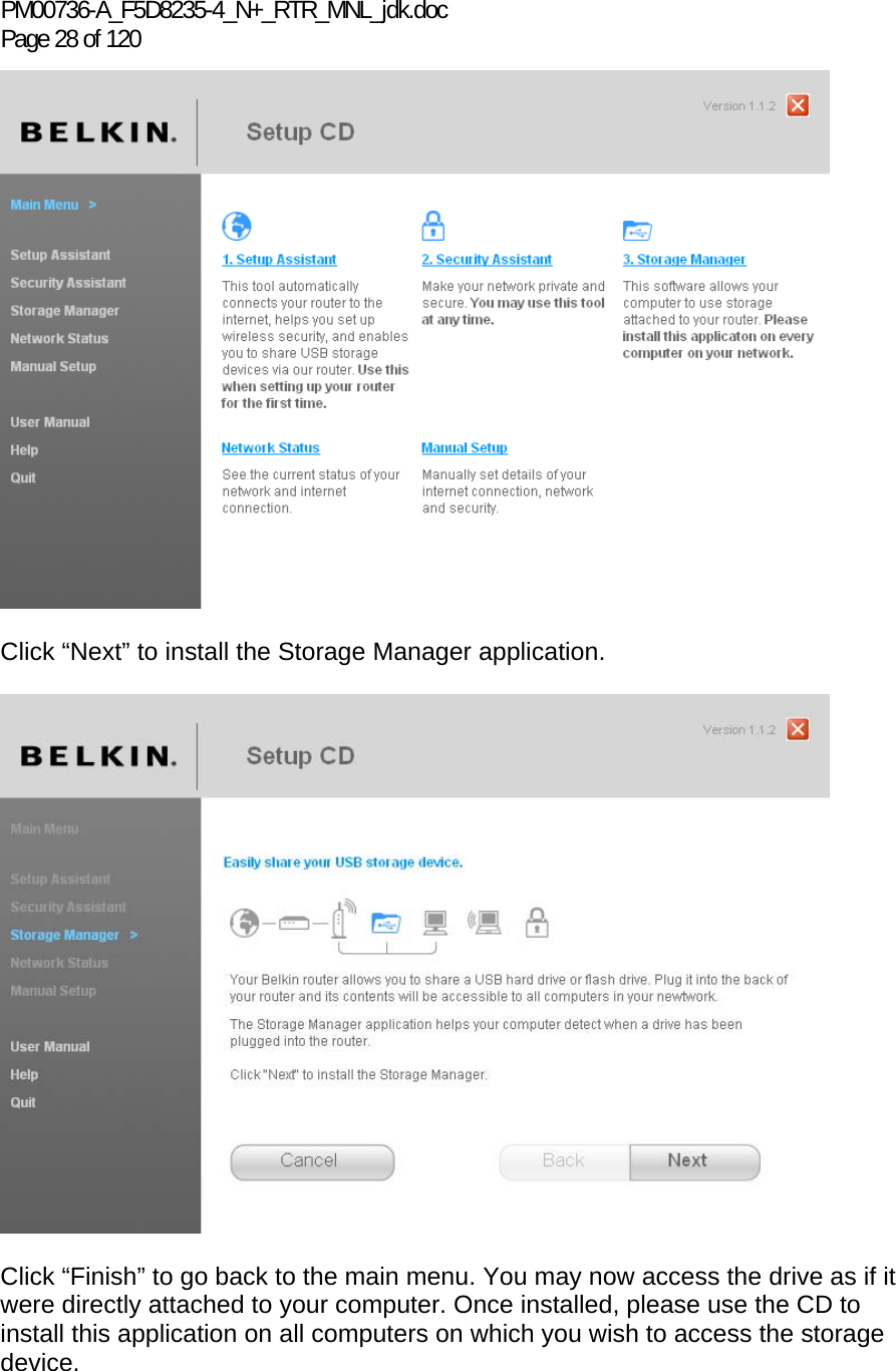
![PM00736-A_F5D8235-4_N+_RTR_MNL_jdk.doc1 Page 27 of 120 [insert EZI_Opt_Done.tif] Storage Manager The Storage Manager is an application that provides easy access to your USB storage device. Once this is installed, your storage device will appear as a drive letter (e.g., D:\) in your “My Computer” folder. You may read and write to this drive as if it were directly attached to your computer. Note that the Router currently supports FAT, FAT32, and NTFS file systems.](https://usermanual.wiki/Belkin/F5D8235V3/User-Guide-1160721-Page-27.png)
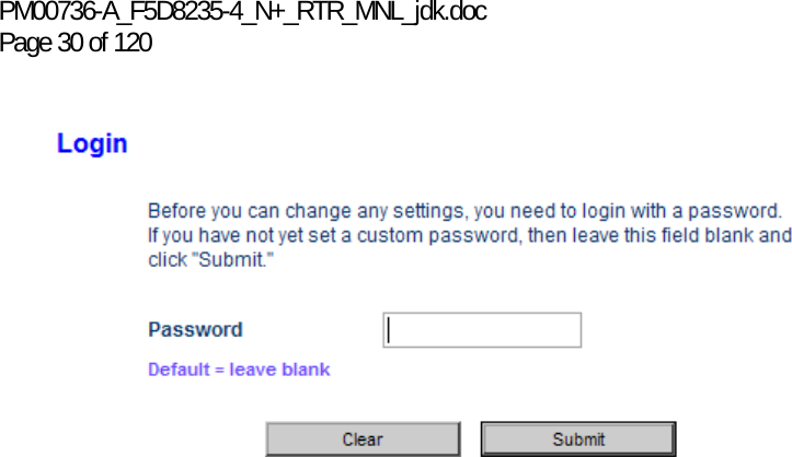
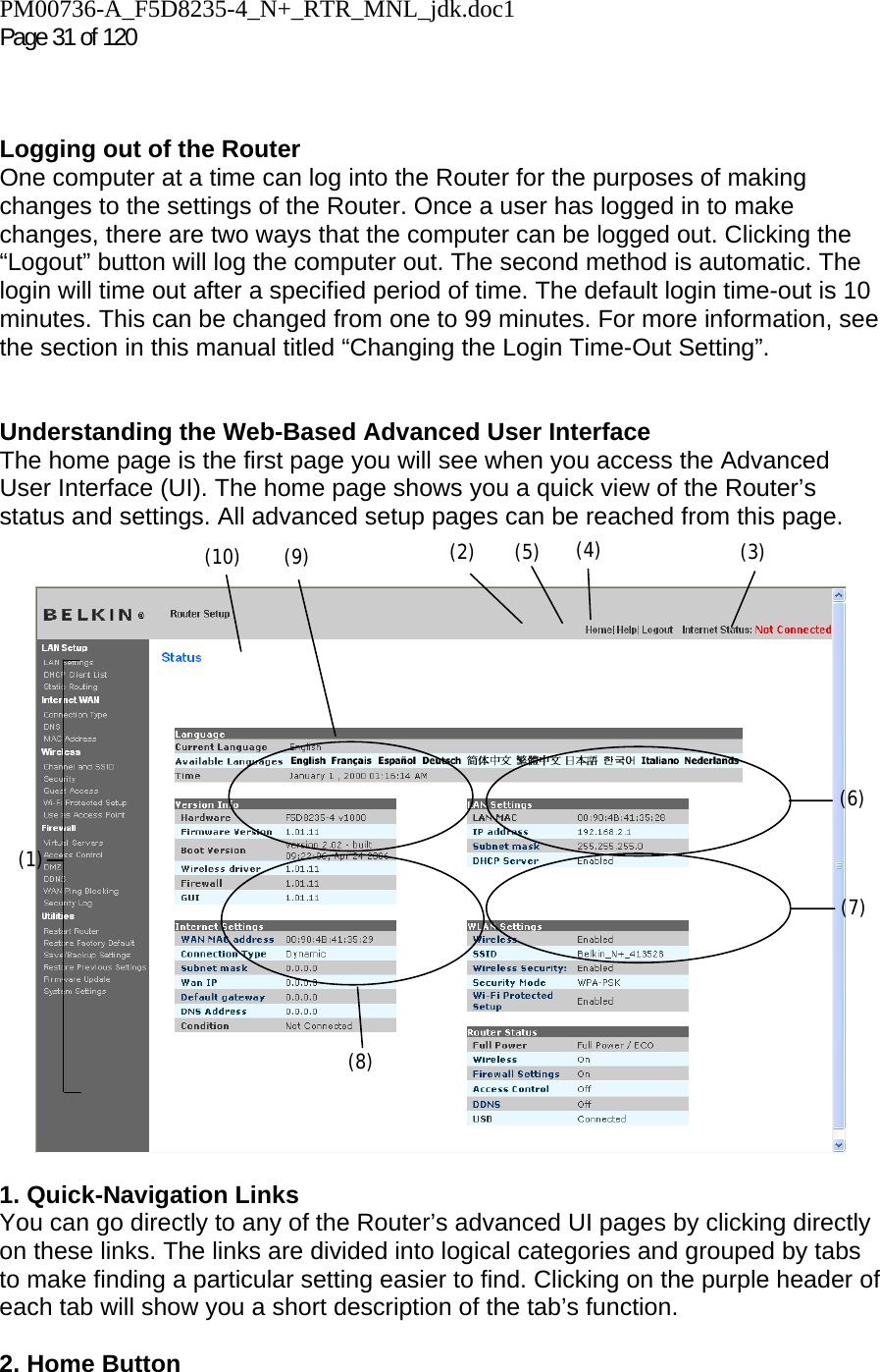
![PM00736-A_F5D8235-4_N+_RTR_MNL_jdk.doc1 Page 29 of 120 Storage Manager also allows you to safely eject the storage device before unplugging it from your Router. This is recommended before unplugging the USB storage device as there might be another user on your network who is accessing the drive. Simply right-click on the “Storage Manager” icon in the system tray and select the appropriate button. Alternatively, you do not need to install the Storage Manager in order to access your storage device. Open a file explorer window and type in the address field: \\192.168.2.1\DeviceName where “DeviceName” is the name that was assigned to the storage device. Your Belkin N+ Wireless Modem Router supports up to four USB storage devices through a separate USB hub (not included). Note that the Router can supply a maximum of 500mA of current to the port, so it is recommended that the hub be externally powered. Additionally, some USB hard drives require more than 500mA and must be externally powered to function. Alternate Setup Method Step 1: Hardware Connections – Follow the Quick Installation Guide See the QIG or Step 1: Hardware Connections from the previous section. Step 2: Set your Computer’s Network Settings to Work with a DHCP Server See the section in this User Manual called “Manually Configuring Network Settings” for directions. Step 3: Configuring the Router Using the Web-Based Advanced User Interface Using your Internet browser, you can access the Router’s Web-Based Advanced User Interface. In your browser, type “192.168.2.1” (do not type in anything else such as “http://” or “www”). Then press the “Enter” key. [use existing tif] Logging into the Router You will see the Router’s home page in your browser window. The home page is visible to any user who wants to see it. To make any changes to the Router’s settings, you have to log in. Clicking the “Login” button or clicking on any one of the links on the home page will take you to the login screen. The Router ships with no password entered. In the login screen, leave the password blank and click the “Submit” button to log in.](https://usermanual.wiki/Belkin/F5D8235V3/User-Guide-1160721-Page-29.png)
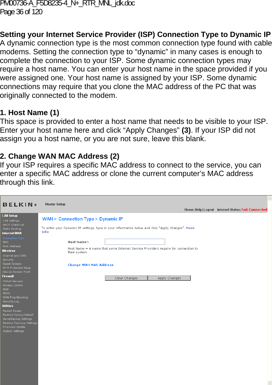
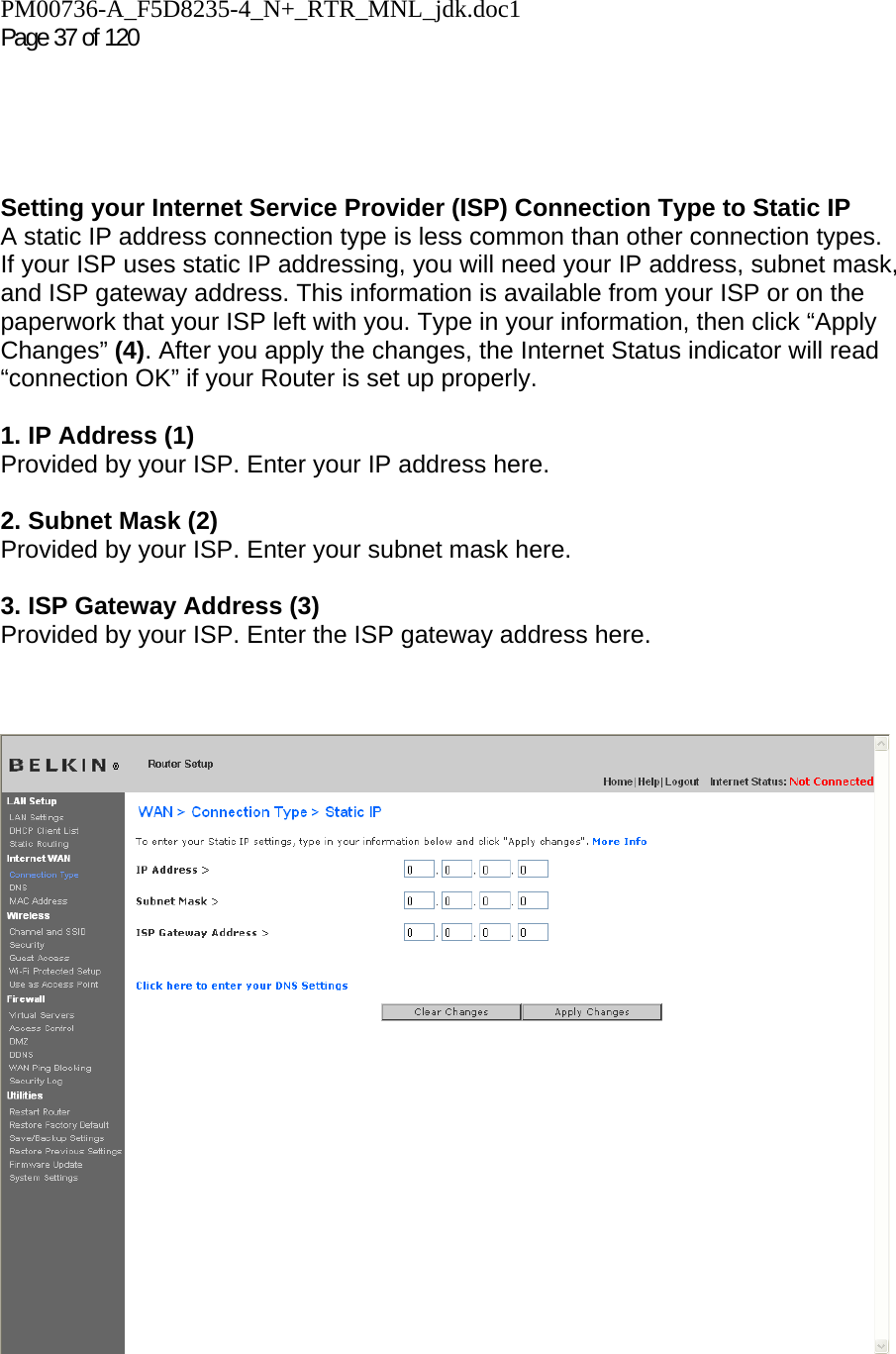
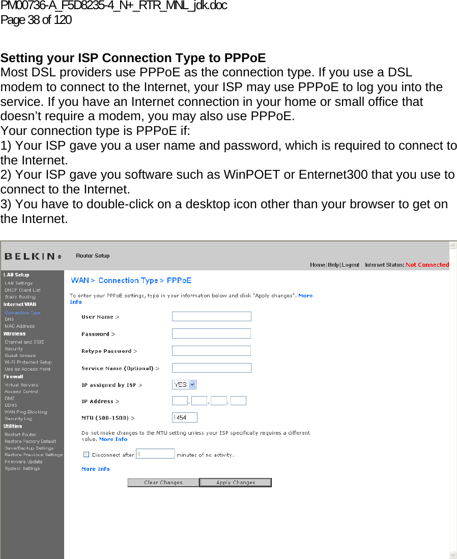
![PM00736-A_F5D8235-4_N+_RTR_MNL_jdk.doc Page 40 of 120 Setting your Internet Service Provider (ISP) Connection Type to Point-to-Point Tunneling Protocol (PPTP) [European Countries Only]. Some ISPs require a connection using PPTP protocol, a type of connection most common in European countries. This sets up a direct connection to the ISP’s system. Type in the information provided by your ISP in the space provided. When you have finished, click “Apply Changes” (9). After you apply the changes, the Internet Status indicator will read “connection OK” if your Router is set up properly. 1. PPTP Account Provided by your ISP. Enter your PPTP account name here. 2. PPTP Password Type in your password and retype it into the “Retype Password” box to confirm it. 3. Host Name Provided by your ISP. Enter your host name here.](https://usermanual.wiki/Belkin/F5D8235V3/User-Guide-1160721-Page-40.png)
![PM00736-A_F5D8235-4_N+_RTR_MNL_jdk.doc Page 42 of 120 Setting your Connection Type if You Are a Telstra® BigPond User [Australia Only] Your user name and password are provided to you by Telstra BigPond. Enter this information below. Choosing your state from the drop-down menu (6) will automatically fill in your login server IP address. If your login server address is different than one provided here, you may manually enter the login server IP address by placing a check in the box next to “User decide login server manually” (4) and type in the address next to “Login Server” (5). When you have entered all of your information, click “Apply Changes” (7). After you apply the changes, the Internet Status indicator will read “connection OK” if your Router is set up properly. [insert Telstra.tif] 1. Select your State Select your state from the drop-down menu (6). The “Login Server” box will automatically be filled in with an IP address. If for some reason this address does not match the address that Telstra has given, you can manually enter the login server address. See “User decide login server manually” (4). 2. User Name Provided by your ISP. Type in your user name here (2).(1) (2) (3) (4) (5) (6) (7)](https://usermanual.wiki/Belkin/F5D8235V3/User-Guide-1160721-Page-42.png)
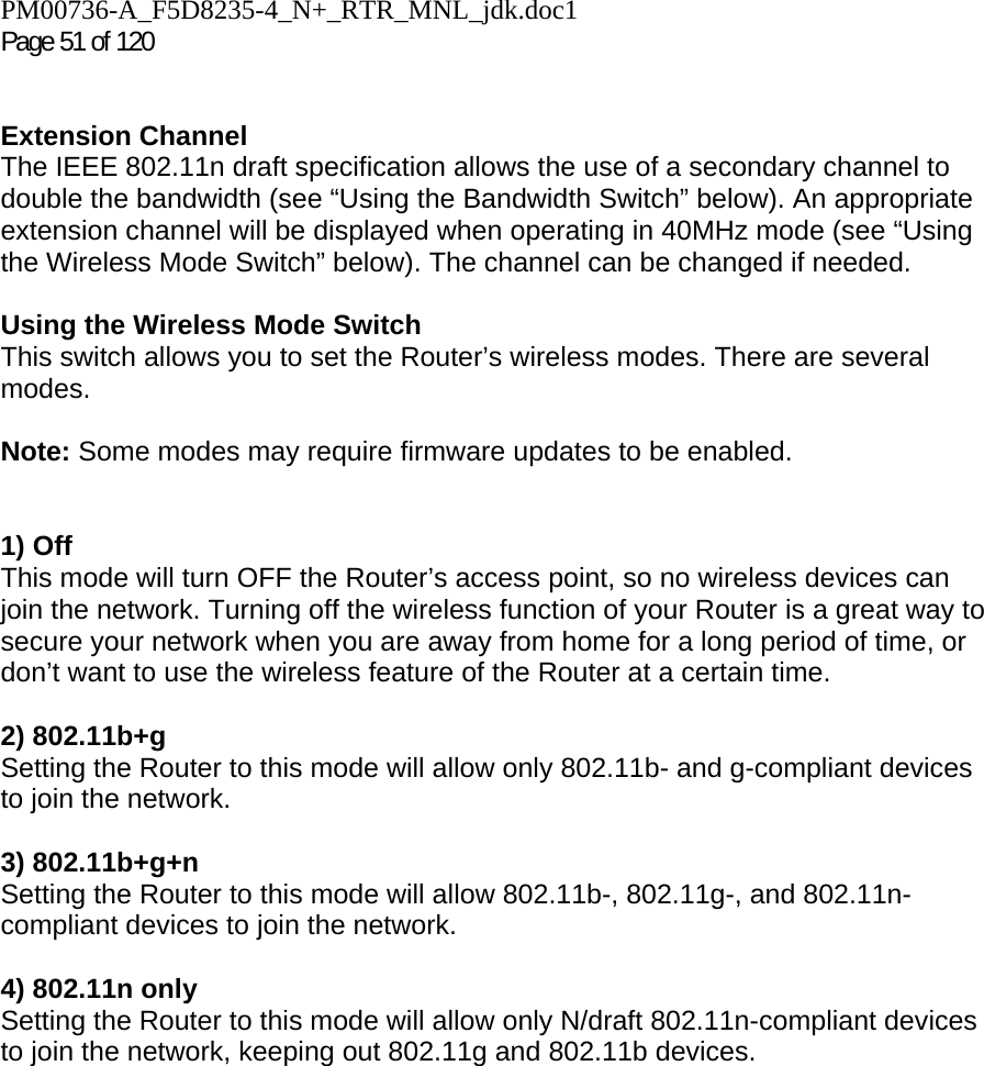
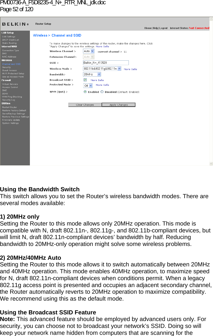
![PM00736-A_F5D8235-4_N+_RTR_MNL_jdk.doc Page 50 of 120 other wireless networks that may be operating in your area. To change the SSID, type in the SSID that you want to use in the SSID field (1) and click “Apply Changes” (2). The change is immediate. If you make a change to the SSID, your wireless-equipped computers may also need to be reconfigured to connect to your new network name. Refer to the documentation of your wireless network adapter for information on making this change. [insert Channel and SSID.tif] Note: Please periodically check for new Router firmware updates from the “Utilities > Firmware update” page. Newer firmware can fix problems, add wireless features, and/or improve wireless performance (see page xx). [Designer, Please match page number to the firmware update section] Changing the Wireless Channel There are a number of operating channels from which you can choose—in the United States, there are 11 and in the United Kingdom (and most of Europe), there are 13. In a small number of other countries, there are other channel requirements. Your Router is configured to operate on the proper channels for the country in which you reside. The channel can be changed if needed. If there are other wireless networks operating in your area, your network should be set to operate on a channel that is different than the other wireless networks. (1)(2)](https://usermanual.wiki/Belkin/F5D8235V3/User-Guide-1160721-Page-50.png)
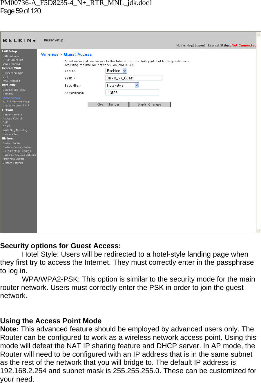
![PM00736-A_F5D8235-4_N+_RTR_MNL_jdk.doc Page 58 of 120 the documentation of your wireless network adapter for information on making this change. Using a Hexadecimal Key A hexadecimal key is a mixture of numbers and letters from A–F and 0–9. 64-bit keys are 10 digits long and can be divided into five two-digit numbers. 128-bit keys are 26 digits long and can be divided into 13 two-digit numbers. For instance: AF 0F 4B C3 D4 = 64-bit key C3 03 0F AF 0F 4B B2 C3 D4 4B C3 D4 E7 = 128-bit key In the boxes below, make up your key by writing in two characters between A–F and 0–9. You will use this key to program the encryption settings on your Router and your wireless computers. [encryption chart.tif][use current image] Note to Mac users: Original Apple AirPort products support 64-bit encryption only. Apple AirPort 2 products can support 64-bit or 128-bit encryption. Please check your product to see which version you are using. If you cannot configure your network with 128-bit encryption, try 64-bit encryption. Guest Access: This option allows guest users access to the Internet while keeping them away from your private network. By default, this option is enabled. Guest users should connect to the Belkin N+ Guest network.](https://usermanual.wiki/Belkin/F5D8235V3/User-Guide-1160721-Page-58.png)

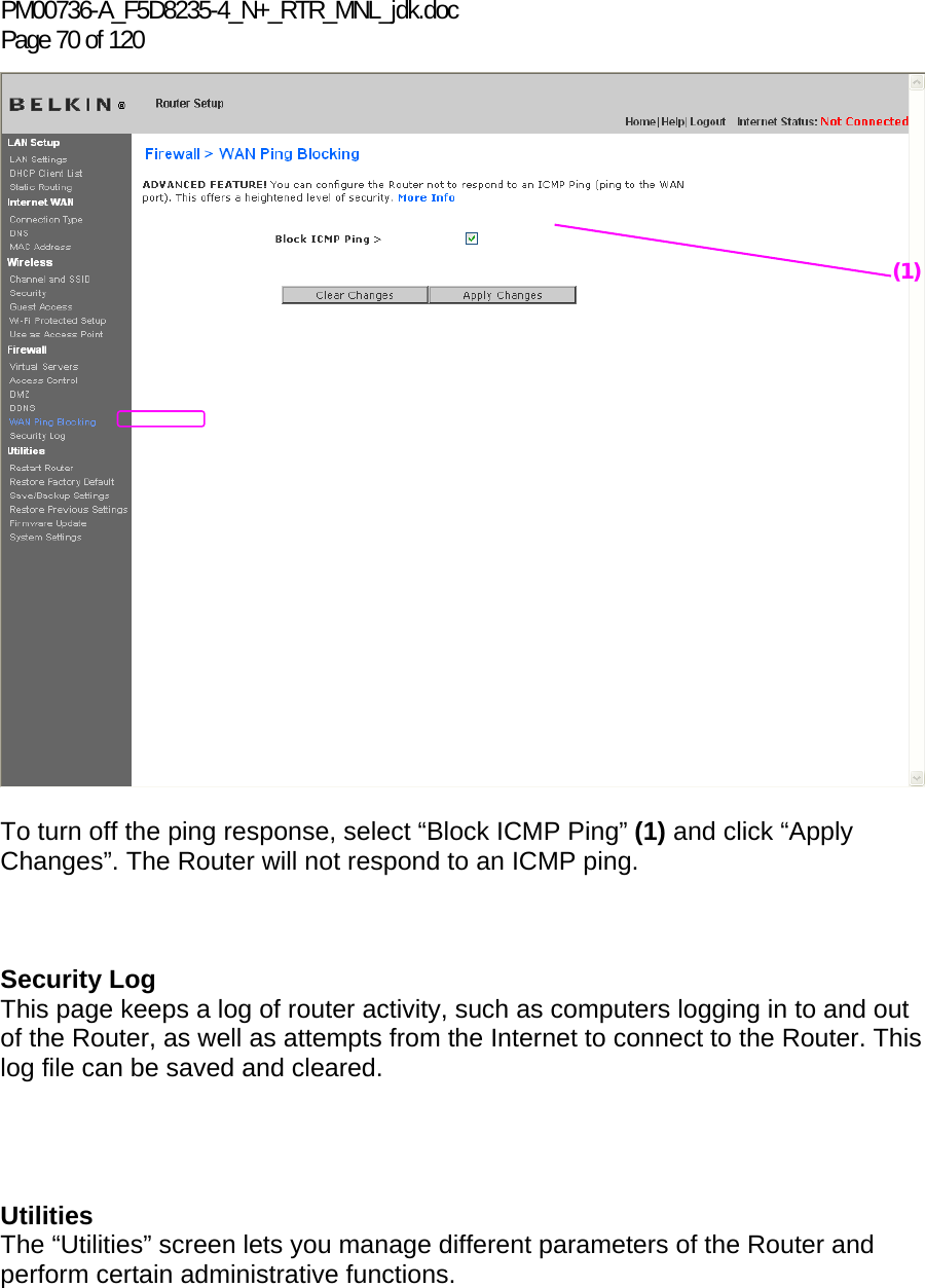
![PM00736-A_F5D8235-4_N+_RTR_MNL_jdk.doc Page 72 of 120 Restarting the Router to Restore Normal Operation 1. Click the “Restart Router” button. 2. The following message will appear. Click “OK”. 9230_Restart_Router_Confirmation.jpg[keep]](https://usermanual.wiki/Belkin/F5D8235V3/User-Guide-1160721-Page-72.png)
![PM00736-A_F5D8235-4_N+_RTR_MNL_jdk.doc1 Page 73 of 120 3. The following message will appear. Restarting the Router can take up to 60 seconds. It is important not to turn off the power to the Router during the restart. 9230_Restart_Router_Confirmed.jpg[keep] 4. A 60-second countdown will appear on the screen. When the countdown reaches zero, the Router will be restarted. The Router home page should appear automatically. If not, type in the Router’s address (default = 192.168.2.1) into the navigation bar of your browser. Restoring Factory Default Settings Using this option will restore all of the settings in the Router to the factory (default) settings. It is recommended that you back up your settings before you restore all of the defaults.](https://usermanual.wiki/Belkin/F5D8235V3/User-Guide-1160721-Page-73.png)
![PM00736-A_F5D8235-4_N+_RTR_MNL_jdk.doc Page 74 of 120 1. Click the “Restore Defaults” button. 2. The following message will appear. Click “OK”. 9230_Restore_Factory_Default_Confirmation.jpg[keep]](https://usermanual.wiki/Belkin/F5D8235V3/User-Guide-1160721-Page-74.png)
![PM00736-A_F5D8235-4_N+_RTR_MNL_jdk.doc1 Page 75 of 120 3. The following message will appear. Restoring the defaults includes restarting the Router. It can take up to 60 seconds. It is important not to turn the power to the Router off during the restart. 9230_Restore_Factory_Default_Confirmed.jpg[keep] 4. A 60-second countdown will appear on the screen. When the countdown reaches zero, the Router’s defaults will be restored. The Router home page should appear automatically. If it does not, type in the Router’s address (default = 192.168.2.1) into the navigation bar of your browser. Saving a Current Configuration You can save your current configuration by using this feature. Saving your configuration will allow you to restore it later if your settings are lost or changed. It is recommended that you back up your current configuration before performing a firmware update.](https://usermanual.wiki/Belkin/F5D8235V3/User-Guide-1160721-Page-75.png)
![PM00736-A_F5D8235-4_N+_RTR_MNL_jdk.doc Page 76 of 120 1. Click “Save”. A window called “File Download” will open. Click “Save”. 9230_Save_Backup_Settings_Download.jpg [keep]](https://usermanual.wiki/Belkin/F5D8235V3/User-Guide-1160721-Page-76.png)
![PM00736-A_F5D8235-4_N+_RTR_MNL_jdk.doc1 Page 77 of 120 2. A window will open that allows you to select the location where you want to save the configuration file. Select a location. You can name the file anything you want, or use the default name “user.conf”. Be sure to name the file so you can locate it yourself later. When you have selected the location and name of the file, click “Save”. [screenshot—PM did not provide] 3. When the save is complete, you will see the window below. Click “Close”. 9230_Save_Backup_Settings_Complete.jpg[keep] The configuration is now saved. Restoring a Previous Configuration This option will allow you to restore a previously saved configuration.](https://usermanual.wiki/Belkin/F5D8235V3/User-Guide-1160721-Page-77.png)
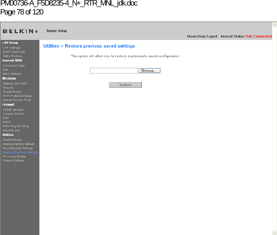
![PM00736-A_F5D8235-4_N+_RTR_MNL_jdk.doc1 Page 79 of 120 1. Click “Browse”. A window will open that allows you to select the location of the configuration file. All configuration files end with a “.conf”. Locate the configuration file you want to restore and double-click on it. 9230_Restore_Saved_Settings_Choose_File.jpg[keep] 2. You will be asked if you want to continue. Click “OK”. 9230_Restore_Saved_Settings_Confirmation.jpg[keep] 3. A reminder window will appear. It will take up to 60 seconds for the configuration restoration to complete. Click “OK”.](https://usermanual.wiki/Belkin/F5D8235V3/User-Guide-1160721-Page-79.png)
![PM00736-A_F5D8235-4_N+_RTR_MNL_jdk.doc Page 80 of 120 9230_Restore_Saved_Settings_Confirmed.jpg[keep] 4. A 60-second countdown will appear on the screen. When the countdown reaches zero, the Router’s configuration will be restored. The Router’s home page should appear automatically. If not, type in the Router’s address (default = 192.168.2.1) into the navigation bar of your browser. Updating the Firmware From time to time, Belkin may release new versions of the Router’s firmware. Firmware updates contain feature improvements and fixes to problems that may have existed. When Belkin releases new firmware, you can download the firmware from the Belkin update website and update your Router’s firmware to the latest version. (1)(2)(3)](https://usermanual.wiki/Belkin/F5D8235V3/User-Guide-1160721-Page-80.png)
![PM00736-A_F5D8235-4_N+_RTR_MNL_jdk.doc Page 82 of 120 [use Firmware Available2.tif] 1. To download the new version of firmware, click “Download”.](https://usermanual.wiki/Belkin/F5D8235V3/User-Guide-1160721-Page-82.png)
![PM00736-A_F5D8235-4_N+_RTR_MNL_jdk.doc1 Page 83 of 120 2. A window will open that allows you to select the location where you want to save the firmware file. Select a location. You can name the file anything you want, or use the default name. Be sure to locate the file in a place where you can locate it yourself later. When you have selected the location, click “Save”. 3. When the save is complete, you will see the following window. Click “Close”. [screenshot—PM did not provide] The download of the firmware is complete. To update the firmware, follow the next steps in “Updating the Router’s Firmware”. Updating the Router’s Firmware 1. In the “Firmware Update” page, click “Browse”. A window will open that allows you to select the location of the firmware update file.](https://usermanual.wiki/Belkin/F5D8235V3/User-Guide-1160721-Page-83.png)
![PM00736-A_F5D8235-4_N+_RTR_MNL_jdk.doc Page 84 of 120 2. Browse to the firmware file you downloaded. Select the file by double-clicking on the file name. [screenshot—PM did not provide] 3. The “Update Firmware” box will now display the location and name of the firmware file you just selected. Click “Update”.](https://usermanual.wiki/Belkin/F5D8235V3/User-Guide-1160721-Page-84.png)
![PM00736-A_F5D8235-4_N+_RTR_MNL_jdk.doc1 Page 85 of 120 4. You will be asked if you are sure you want to continue. Click “OK”. 9230_Firmware_Update_Confirmation.jpg[keep] 5. You will see one more message. This message tells you that the Router may not respond for as long as one minute as the firmware is loaded into the Router and the Router is rebooted. Click “OK”.](https://usermanual.wiki/Belkin/F5D8235V3/User-Guide-1160721-Page-85.png)
![PM00736-A_F5D8235-4_N+_RTR_MNL_jdk.doc Page 86 of 120 9230_Firmware_Update_Confirmed.jpg[keep] 6. A 60-second countdown will appear on the screen. When the countdown reaches zero, the Router firmware update will be complete. The Router home page should appear automatically. If not, type in the Router’s address (default = 192.168.2.1) into the navigation bar of your browser. Changing System Settings The “System Settings” page is where you can enter a new administrator password, set the time zone, or enable remote management. Setting or Changing the Administrator Password The Router ships with NO password entered. If you wish to add a password for greater security, you can set a password here. Write down your password and keep it in a safe place, as you will need it if you need to log into the Router in the future. It is also recommended that you set a password if you plan to use the remote management feature of your Router. [insert Admin_password.tif] Changing the Login Time-Out Setting The login time-out option allows you to set the period of time that you can be logged into the Router’s advanced setup interface. The timer starts when there has been no activity. For example, imagine you have made some changes in the advanced setup interface, then left your computer alone without clicking “Logout”. Assuming the time-out is set to 10 minutes, 10 minutes after you leave, the login session will expire. You will have to log into the Router again to make any more changes. The login time-out option is for security purposes and the default is set](https://usermanual.wiki/Belkin/F5D8235V3/User-Guide-1160721-Page-86.png)
![PM00736-A_F5D8235-4_N+_RTR_MNL_jdk.doc1 Page 87 of 120 to 10 minutes. Note: Only one computer can be logged into the Router’s advanced setup interface at one time. Setting the Time and Time Zone The Router keeps time by connecting to a Simple Network Time Protocol (SNTP) server. This allows the Router to synchronize the system clock to the global Internet. The synchronized clock in the Router is used to record the security log and control client filtering. Select the time zone that you reside in. You have the option to select a primary and a backup NTP server to keep your Router’s clock synchronized. Select your desired NPT server from the drop-down box, or simply keep it as is. If you reside in an area that observes daylight saving, then place a check mark in the box next to “Enable Daylight Saving”. The system clock may not update immediately. Allow at least 15 minutes for the Router to contact the time servers on the Internet and get a response. You cannot set the clock yourself. [insert Time Zone.tif] Enabling Remote Management Before you enable this advanced feature of your Belkin Router, MAKE SURE YOU HAVE SET THE ADMINISTRATOR PASSWORD. Remote management allows you to make changes to your Router’s settings from anywhere on the Internet. There are two methods of remotely managing the Router. The first is to allow access to the Router from anywhere on the Internet by selecting “Any IP address can remotely manage the Router”. By typing in your WAN IP address from any computer on the Internet, you will be presented with a login screen where you need to type in the password of your Router. The second method is to allow a specific IP address only to remotely manage the Router. This is more secure, but less convenient. To use this method, enter the IP address you know you will be accessing the Router from in the space provided and select “Only this IP address can remotely manage the Router”. Before you enable this function, it is STRONGLY RECOMMENDED that you set your](https://usermanual.wiki/Belkin/F5D8235V3/User-Guide-1160721-Page-87.png)
![PM00736-A_F5D8235-4_N+_RTR_MNL_jdk.doc Page 88 of 120 administrator password. Leaving the password empty will potentially open your Router to intrusion. Advanced Feature: The “Remote Access Port” option allows you to configure the desired “Remote Access Port for Remote Management” feature. The default access port is set to port 80. [insert remote_mgmt] Enabling/Disabling UPnP UPnP (Universal Plug-and-Play) is yet another advanced feature offered by your Belkin Router. It is a technology that offers seamless operation of voice messaging, video messaging, games, and other applications that are UPnP-compliant. Some applications require the Router’s firewall to be configured in a specific way to operate properly. This usually requires opening TCP and UDP ports, and in some instances, setting trigger ports. An application that is UPnP-compliant has the ability to communicate with the Router, basically “telling” the Router which way it needs the firewall configured. The Router ships with the UPnP feature enabled. [insert Upnp.tif] Enabling/Disabling Auto Firmware Update This innovation provides the Router with the built-in capability to automatically check for a new version of firmware and alert you that the new firmware is available. When you log into the Router’s advanced interface, the Router will perform a check to see if new firmware is available. If so, you will be notified. You can choose to download the new version or ignore it.](https://usermanual.wiki/Belkin/F5D8235V3/User-Guide-1160721-Page-88.png)
![PM00736-A_F5D8235-4_N+_RTR_MNL_jdk.doc1 Page 89 of 120 [insert Auto_Update_FW.tif] ECO Mode: This option allows you to turn off the wireless radio automatically at set periods of time in order to save power. Click the check box to turn off the radio at the times shown in the drop-down boxes. Manually Configuring Network Settings Set up the computer that is connected to the cable or DSL modem FIRST using these steps. You can also use these steps to add computers to your Router after the Router has been set up to connect to the Internet. Manually Configuring Network Settings in Mac OS up to 9.x](https://usermanual.wiki/Belkin/F5D8235V3/User-Guide-1160721-Page-89.png)
![PM00736-A_F5D8235-4_N+_RTR_MNL_jdk.doc Page 90 of 120 1. Pull down the Apple menu. Select “Control Panels” and select “TCP/IP”. 2. You will see the TCP/IP control panel. Select “Ethernet Built-In” or “Ethernet” in the “Connect via:” drop-down menu (1). [xxxxxxx][use current image] [keep] 3. Next to “Configure” (2), if “Manually” is selected, your Router will need to be set up for a static IP connection type. Write the address information in the table below. You will need to enter this information into the Router. [MacOS9 chart.tif] [use current image] [keep] (1) (2)](https://usermanual.wiki/Belkin/F5D8235V3/User-Guide-1160721-Page-90.png)
![PM00736-A_F5D8235-4_N+_RTR_MNL_jdk.doc1 Page 91 of 120 4. If not already set, at “Configure:”, choose “Using DHCP Server”. This will tell the computer to obtain an IP address from the Router. [xxxxxxx] [use current image] [keep] 5. Close the window. If you made any changes, the following window will appear. Click “Save”. [xxxxxxx] [use current image] [keep] Restart the computer. When the computer restarts, your network settings are now configured for use with the Router. Manually Configuring Network Settings in Mac OS X 1. Click on the “System Preferences” icon. [xxxxxxx] [use current image] [keep] 2. Select “Network” (1) from the “System Preferences” menu. [xxxxxxx] [use current image] [keep] 2 2 (1)](https://usermanual.wiki/Belkin/F5D8235V3/User-Guide-1160721-Page-91.png)
![PM00736-A_F5D8235-4_N+_RTR_MNL_jdk.doc Page 92 of 120 3. Select “Built-in Ethernet” (2) next to “Show” in the Network menu. [xxxxxxx] [use current image] [keep] 4. Select the “TCP/IP” tab (3). Next to “Configure” (4), you should see “Manually” or “Using DHCP”. If you do not, check the PPPoE tab (5) to make sure that “Connect using PPPoE” is NOT selected. If it is, you will need to configure your Router for a PPPoE connection type using your user name and password. 5. If “Manually” is selected, your Router will need to be set up for a static IP connection type. Write the address information in the table below. You will need to enter this information into the Router. [MacOS9 chart.tif] [use current image] [keep] 6. If not already selected, select “Using DHCP” next to “Configure” (4), then click “Apply Now”. Your network settings are now configured for use with the Router. (2) (3) (4) (5)](https://usermanual.wiki/Belkin/F5D8235V3/User-Guide-1160721-Page-92.png)
![PM00736-A_F5D8235-4_N+_RTR_MNL_jdk.doc Page 94 of 120 4. In the “Local Area Connection Properties” window, click “Internet Protocol (TCP/IP)” and click the “Properties” button. The following screen will appear: [XP TCPIP.tif] [use current image] [keep] 5. If “Use the following IP address” (2) is selected, your Router will need to be set up for a static IP connection type. Write the address information the table below. You will need to enter this information into the Router. [win2k settings chart.tif] [use current image] [keep] 6. If not already selected, select “Obtain an IP address automatically” (1) and “Obtain DNS server address automatically” (3). Click “OK”. Your network settings are now configured for use with the Router. (1) (2) (3)](https://usermanual.wiki/Belkin/F5D8235V3/User-Guide-1160721-Page-94.png)
![PM00736-A_F5D8235-4_N+_RTR_MNL_jdk.doc1 Page 95 of 120 Manually Configuring Network Settings in Windows 98 or Me 1. Right-click on “My Network Neighborhood” and select “Properties” from the drop-down menu. 2. Select “TCP/IP -> settings” for your installed network adapter. You will see the following window. [98 Me IP properties.tif] [use current image] [keep] 3. If “Specify and IP address” is selected, your Router will need to be set up for a static IP connection type. Write the address information in the table below. You will need to enter this information into the Router. 4. Write the IP address and subnet mask from the “IP Address” tab (3). 5. Click the “Gateway” tab (2). Write the gateway address down in the chart. 6. Click the “DNS Configuration” tab (1). Write the DNS address(es) in the chart. (1) (2)(3)](https://usermanual.wiki/Belkin/F5D8235V3/User-Guide-1160721-Page-95.png)
![PM00736-A_F5D8235-4_N+_RTR_MNL_jdk.doc Page 96 of 120 [win2k settings chart.tif] [keep] [use current image] 7. If not already selected, select “Obtain IP address automatically” on the IP address tab. Click “OK”. Restart the computer. When the computer restarts, your network settings are now configured for use with the Router.](https://usermanual.wiki/Belkin/F5D8235V3/User-Guide-1160721-Page-96.png)
![PM00736-A_F5D8235-4_N+_RTR_MNL_jdk.doc1 Page 97 of 120 Recommended Web Browser Settings In most cases, you will not need to make any changes to your web browser’s settings. If you are having trouble accessing the Internet or the Web-Based Advanced User Interface, then change your browser’s settings to the recommended settings in this section. Microsoft® Internet Explorer 4.0 or Higher 1. Start your web browser. Select “Tools” then “Internet Options”. [insert Internet_options.tif] 2. In the “Internet Options” screen, there are three selections: “Never dial a connection”, “Dial whenever a network connection is not present”, and “Always dial my default connection”. If you can make a selection, select “Never dial a connection”. If you cannot make a selection, go to the next step.](https://usermanual.wiki/Belkin/F5D8235V3/User-Guide-1160721-Page-97.png)
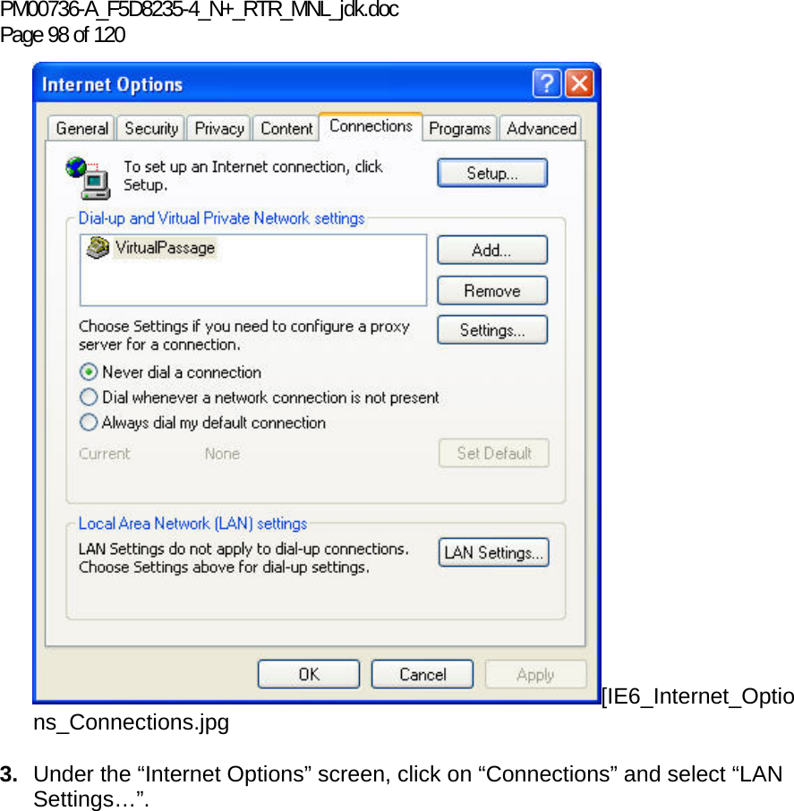
![PM00736-A_F5D8235-4_N+_RTR_MNL_jdk.doc1 Page 99 of 120 4. Make sure there are no check marks next to any of the displayed options: “Automatically detect settings”, “Use automatic configuration script”, and “Use a proxy server”. Click “OK”. Then click “OK” again in the “Internet Options” page. [IE6_Internet_Options_Connections_LAN_Settings.jpg Netscape® Navigator® 4.0 or Higher 1. Start Netscape. Click on “Edit” then “Preferences”. 2. In the “Preferences” window, click on “Advanced” then select “Proxies”. In the “Proxies” window, select “Direct connection to the Internet”. [NS6 Setup 1.tif]](https://usermanual.wiki/Belkin/F5D8235V3/User-Guide-1160721-Page-99.png)
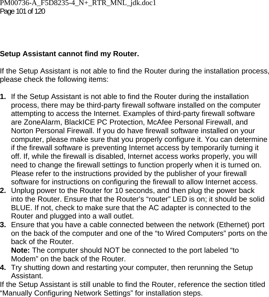
![PM00736-A_F5D8235-4_N+_RTR_MNL_jdk.doc Page 100 of 120 Troubleshooting Setup Assistant CD does not automatically start. If the CD-ROM does not start the Setup Assistant automatically, it could be that the computer is running other applications that are interfering with the CD drive. 1. If the Setup Assistant Welcome screen does not appear within 15-20 seconds, open up your CD-ROM drive by double-clicking on the “My Computer” icon that is located on your desktop. 2. Next, double-click on the CD-ROM drive that the Setup Assistant CD has been placed in to start the installation. 3. The Setup Assistant should start within a few seconds. If, instead, a window appears showing the files on the CD, double-click on the icon labeled “SetupAssistant”. 4. If the Setup Assistant still does not start, reference the section titled “Manually Configuring Network Settings” (page xx [confirm page no. ]) of this User Manual for an alternative setup method).](https://usermanual.wiki/Belkin/F5D8235V3/User-Guide-1160721-Page-100.png)
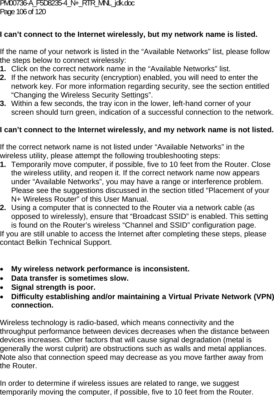
![PM00736-A_F5D8235-4_N+_RTR_MNL_jdk.doc1 Page 107 of 120 Changing the wireless channel—Depending on local wireless traffic and interference, switching the wireless channel of your network can improve performance and reliability. The default channel the Router is shipped with is channel 11; you may choose from several other channels depending on your region. See the section on page XX [insert the correct pg no.] entitled “Changing the Wireless Channel” for instructions on how to choose other channels. Limiting the wireless transmit rate—Limiting the wireless transmit rate can help improve the maximum wireless range and connection stability. Most wireless cards have the ability to limit the transmission rate. To change this property, go to the Windows Control Panel, open “Network Connections” and double-click on your wireless card’s connection. In the properties dialog, select the “Configure” button on the “General” tab (Windows 98 users will have to select the wireless card in the list box and then click “Properties”), then choose the “Advanced” tab and select the rate property. Wireless client cards are usually set to automatically adjust the wireless transmit rate for you, but doing so can cause periodic disconnects when the wireless signal is too weak; as a rule, slower transmission rates are more stable. Experiment with different connection rates until you find the best one for your environment. Note that all available transmission rates should be acceptable for browsing the Internet. For more assistance, see your wireless card’s user manual.](https://usermanual.wiki/Belkin/F5D8235V3/User-Guide-1160721-Page-107.png)
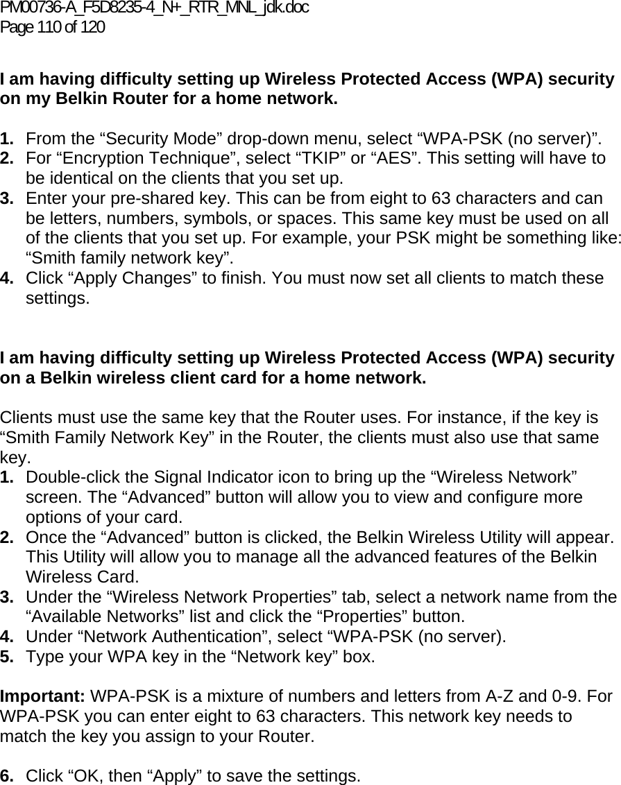
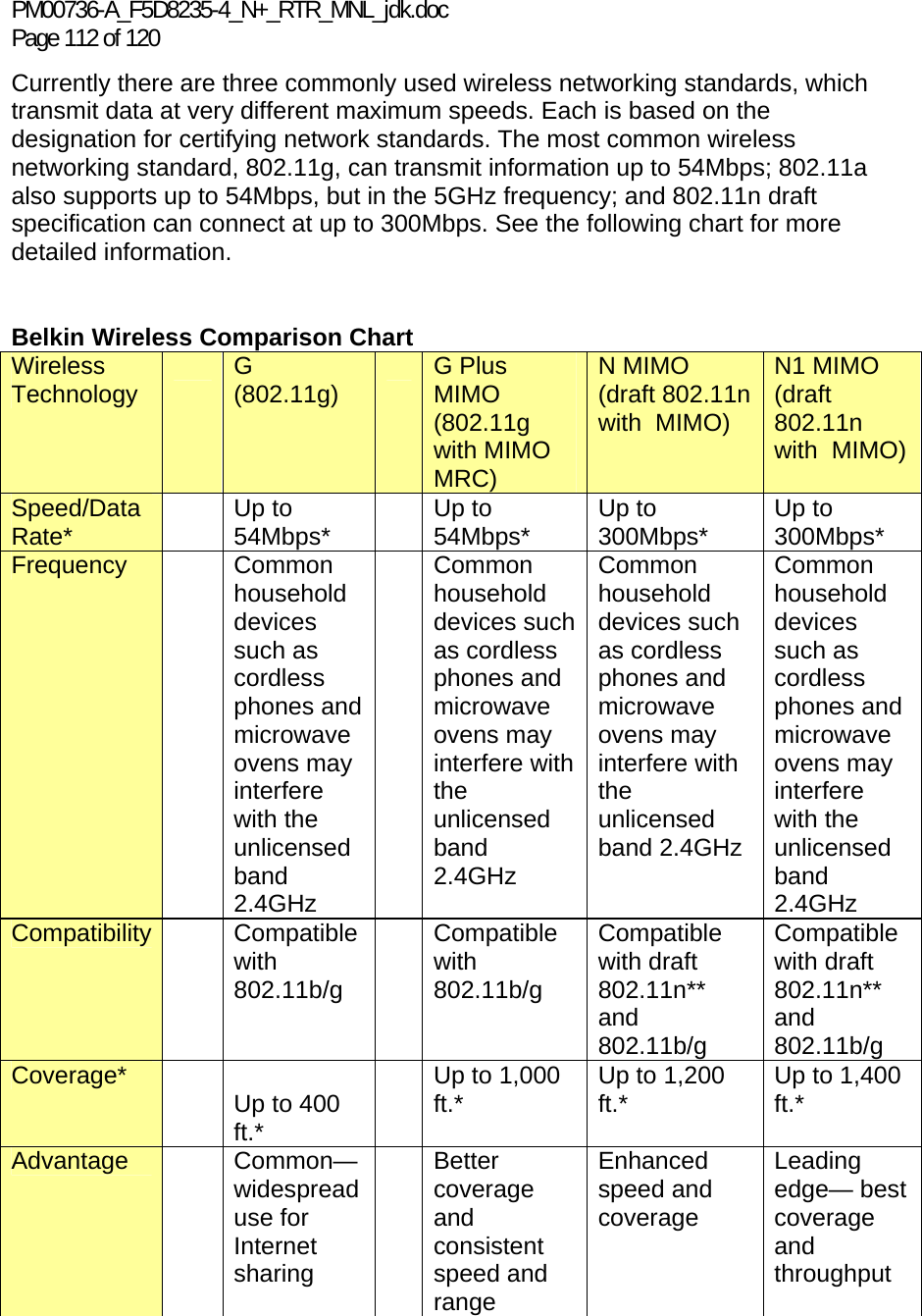
![PM00736-A_F5D8235-4_N+_RTR_MNL_jdk.doc1 Page 111 of 120 I am NOT using a Belkin client card for a home network and I am having difficulty setting up Wireless Protected Access (WPA) security. If you are not using a Belkin Wireless Desktop or Wireless Notebook Network Card that is not equipped with WPA-enabled software, a file from Microsoft called “Windows XP Support Patch for Wireless Protected Access” is available for free download. Download the patch from Microsoft by searching the knowledge base for Windows XP WPA. Note: The file that Microsoft has made available works only with Windows XP. Other operating systems are not supported at this time. You also need to ensure that the wireless card’s manufacturer supports WPA and that you have downloaded and installed the latest driver from their support site. Supported Operating Systems: • Windows XP Professional • Windows XP Home Edition 1. Under Windows XP, click “Start > Control Panel > Network Connections”. 2. Right-clicking on the “Wireless Networks” tab will display the following screen. Ensure the “Use Windows to configure my wireless network settings” check box is checked. [need image] 3. Under the “Wireless Networks” tab, click the “Configure” button and you will see the following screen. [need image] 4. For a home or small business user, select “WPA-PSK” under “Network Administration”. Note: Select WPA (with radius server) if you are using this computer to connect to a corporate network that supports an authentication server such as a radius server. Please consult your network administrator for further information. 5. Select “TKIP” or “AES” under “Date Encryption”. This setting will have to be identical to the Router that you set up. 6. Type in your encryption key in the “Network key” box. Important: Enter your pre-shared key. This can be from eight to 63 characters and can be letters, numbers, or symbols. This same key must be used on all of the clients that you set up. 7. Click “OK” to apply settings. What’s the difference between 802.11g and draft 802.11n?](https://usermanual.wiki/Belkin/F5D8235V3/User-Guide-1160721-Page-111.png)
![PM00736-A_F5D8235-4_N+_RTR_MNL_jdk.doc Page 116 of 120 This device may not be used for setting up outdoor radio links in France and in some areas the RF output power may be limited to 10 mW EIRP in the frequency range of 2454 – 2483.5 MHz. For detailed information the end-user should contact the national spectrum authority in France. Česky [Czech] [Jméno výrobce] tímto prohlašuje, že tento [typ zařízení] je ve shodě se základními požadavky a dalšími příslušnými ustanoveními směrnice 1999/5/ES. Dansk [Danish] Undertegnede [fabrikantens navn] erklærer herved, at følgende udstyr [udstyrets typebetegnelse] overholder de væsentlige krav og øvrige relevante krav i direktiv 1999/5/EF. Deutsch [German] Hiermit erklärt [Name des Herstellers], dass sich das Gerät [Gerätetyp] in Übereinstimmung mit den grundlegenden Anforderungen und den übrigen einschlägigen Bestimmungen der Richtlinie 1999/5/EG befindet. Eesti [Estonian] Käesolevaga kinnitab [tootja nimi = name of manufacturer] seadme [seadme tüüp = type of equipment] vastavust direktiivi 1999/5/EÜ põhinõuetele ja nimetatud direktiivist tulenevatele teistele asjakohastele sätetele. English Hereby, [name of manufacturer], declares that this [type of equipment] is in compliance with the essential requirements and other relevant provisions of Directive 1999/5/EC. Español [Spanish] Por medio de la presente [nombre del fabricante] declara que el [clase de equipo] cumple con los requisitos esenciales y cualesquiera otras disposiciones aplicables o exigibles de la Directiva 1999/5/CE. Ελληνική [Greek] ΜΕ ΤΗΝ ΠΑΡΟΥΣΑ [name of manufacturer] ΔΗΛΩΝΕΙ ΟΤΙ [type of equipment] ΣΥΜΜΟΡΦΩΝΕΤΑΙ ΠΡΟΣ ΤΙΣ ΟΥΣΙΩΔΕΙΣ ΑΠΑΙΤΗΣΕΙΣ ΚΑΙ ΤΙΣ ΛΟΙΠΕΣ ΣΧΕΤΙΚΕΣ ΔΙΑΤΑΞΕΙΣ ΤΗΣ ΟΔΗΓΙΑΣ 1999/5/ΕΚ. Français [French] Par la présente [nom du fabricant] déclare que l'appareil [type d'appareil] est conforme aux exigences essentielles et aux autres dispositions pertinentes de la directive 1999/5/CE. Italiano [Italian] Con la presente [nome del costruttore] dichiara che questo [tipo di apparecchio] è conforme ai requisiti essenziali ed alle altre disposizioni pertinenti stabilite dalla direttiva 1999/5/CE. Latviski [Latvian] Ar šo [name of manufacturer / izgatavotāja nosaukums] deklarē, ka [type of equipment / iekārtas tips] atbilst Direktīvas 1999/5/EK būtiskajām prasībām un citiem ar to saistītajiem noteikumiem. Lietuvių [Lithuanian] Šiuo [manufacturer name] deklaruoja, kad šis [equipment type] atitinka esminius reikalavimus ir kitas 1999/5/EB Direktyvos nuostatas. Nederlands [Dutch] Hierbij verklaart [naam van de fabrikant] dat het toestel [type van toestel] in overeenstemming is met de essentiële eisen en de andere relevante bepalingen van richtlijn 1999/5/EG. Malti [Maltese] Hawnhekk, [isem tal-manifattur], jiddikjara li dan [il-mudel tal-prodott] jikkonforma mal-ħtiġijiet essenzjali u ma provvedimenti oħrajn relevanti li hemm fid-Dirrettiva 1999/5/EC. Magyar [Hungarian] Alulírott, [gyártó neve] nyilatkozom, hogy a [... típus] megfelel a vonatkozó alapvetõ követelményeknek és az 1999/5/EC irányelv egyéb elõírásainak.](https://usermanual.wiki/Belkin/F5D8235V3/User-Guide-1160721-Page-116.png)
![PM00736-A_F5D8235-4_N+_RTR_MNL_jdk.doc1 Page 117 of 120 Polski [Polish] Niniejszym [nazwa producenta] oświadcza, że [nazwa wyrobu] jest zgodny z zasadniczymi wymogami oraz pozostałymi stosownymi postanowieniami Dyrektywy 1999/5/EC. Português [Portuguese] [Nome do fabricante] declara que este [tipo de equipamento] está conforme com os requisitos essenciais e outras disposições da Directiva 1999/5/CE. Slovensko [Slovenian] [Ime proizvajalca] izjavlja, da je ta [tip opreme] v skladu z bistvenimi zahtevami in ostalimi relevantnimi določili direktive 1999/5/ES. Slovensky [Slovak] [Meno výrobcu] týmto vyhlasuje, že [typ zariadenia] spĺňa základné požiadavky a všetky príslušné ustanovenia Smernice 1999/5/ES. Suomi [Finnish] [Valmistaja = manufacturer] vakuuttaa täten että [type of equipment = laitteen tyyppimerkintä] tyyppinen laite on direktiivin 1999/5/EY oleellisten vaatimusten ja sitä koskevien direktiivin muiden ehtojen mukainen. Svenska [Swedish] Härmed intygar [företag] att denna [utrustningstyp] står I överensstämmelse med de väsentliga egenskapskrav och övriga relevanta bestämmelser som framgår av direktiv 1999/5/EG.](https://usermanual.wiki/Belkin/F5D8235V3/User-Guide-1160721-Page-117.png)