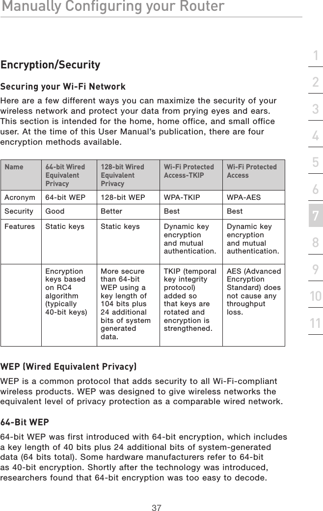
Belkin F5D8630-4 ADSL Modem with Wireless Pre-N Router User Manual P74911uk F5D8630 4 man indd
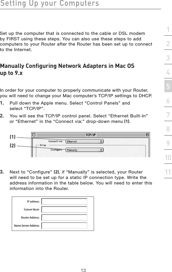
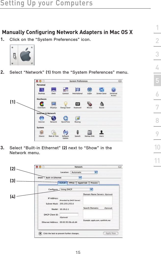
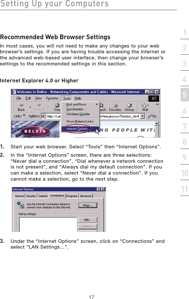
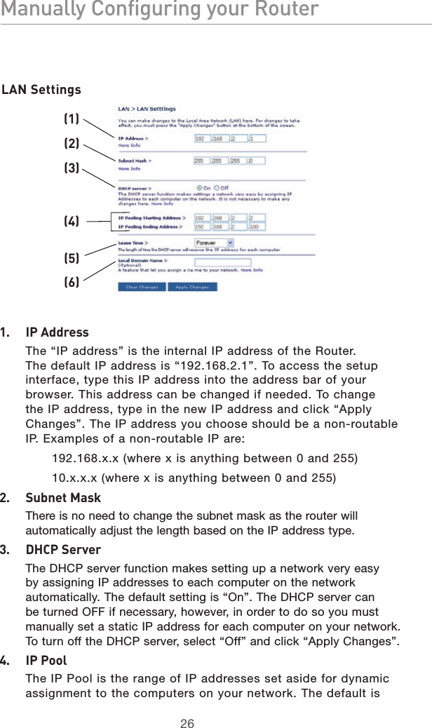
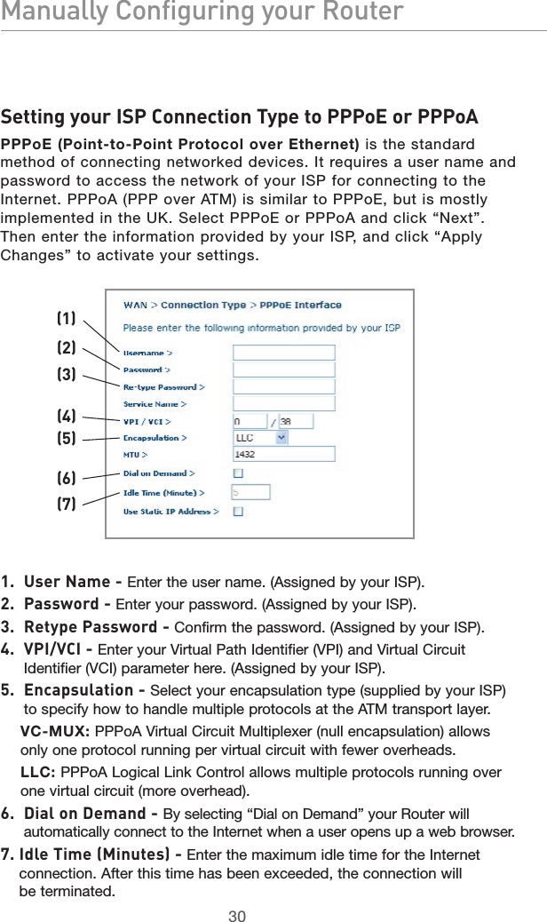
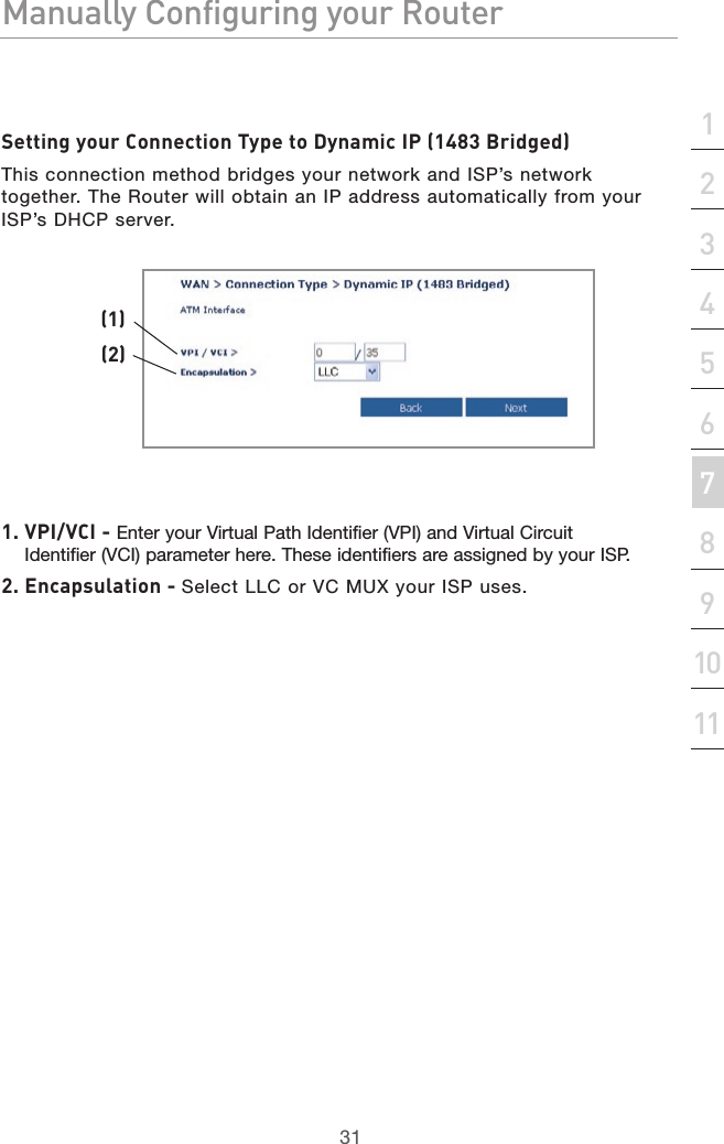
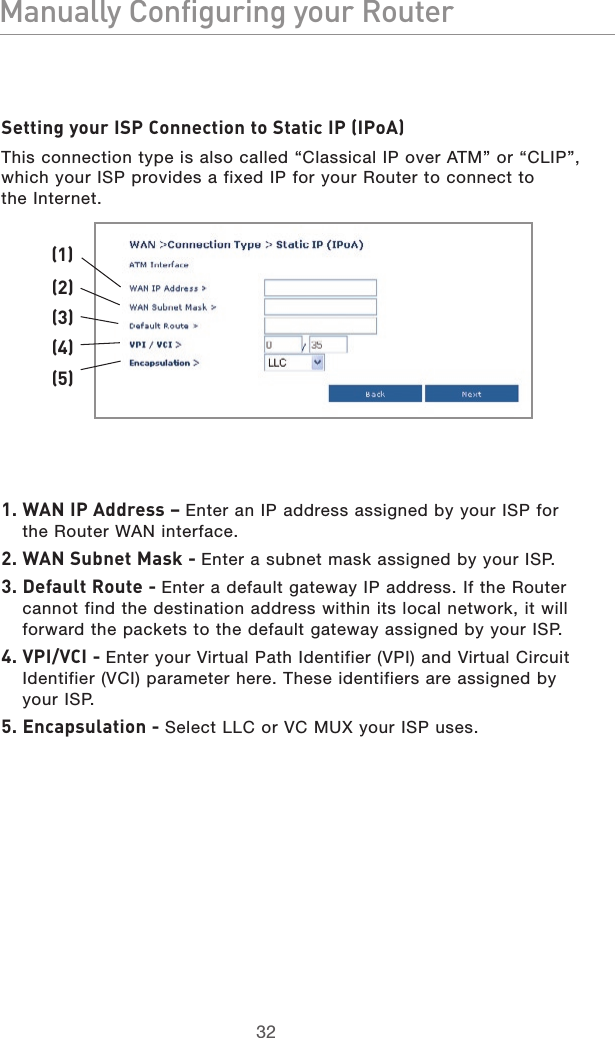
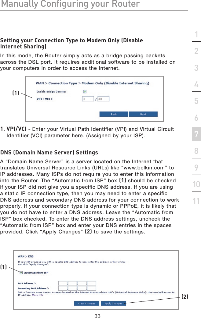
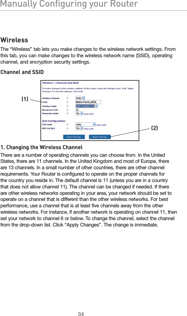
Belkin International, Inc. ADSL Modem with Wireless Pre-N Router P74911uk F5D8630 4 man indd
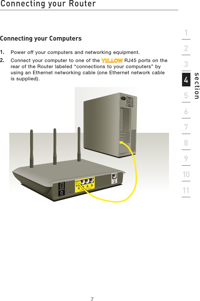
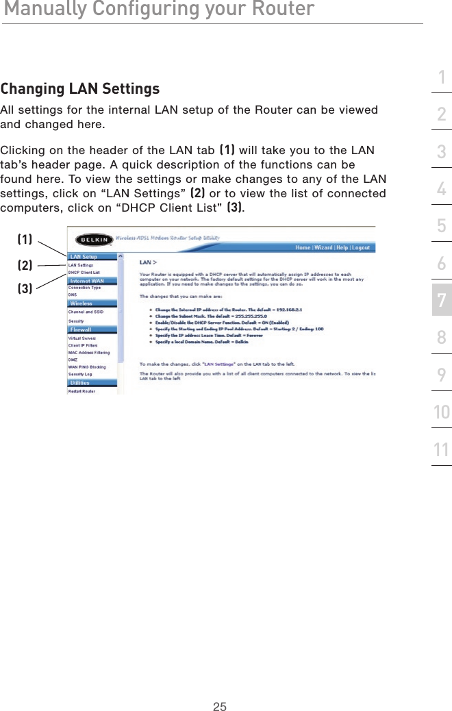
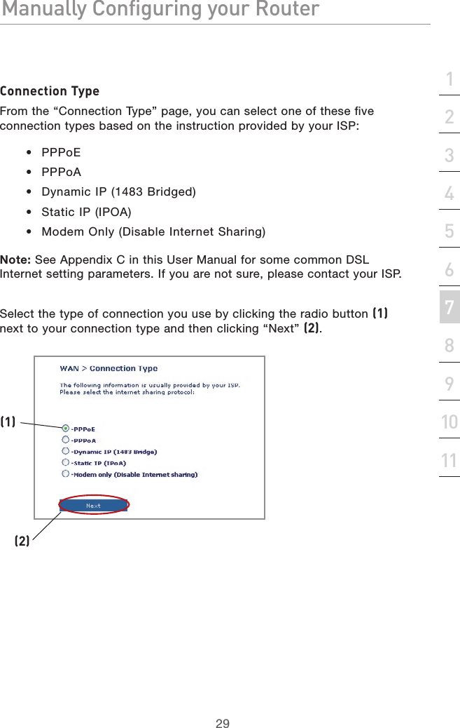
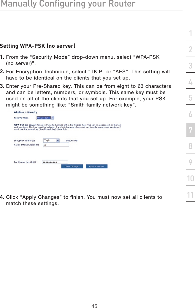
Belkin >
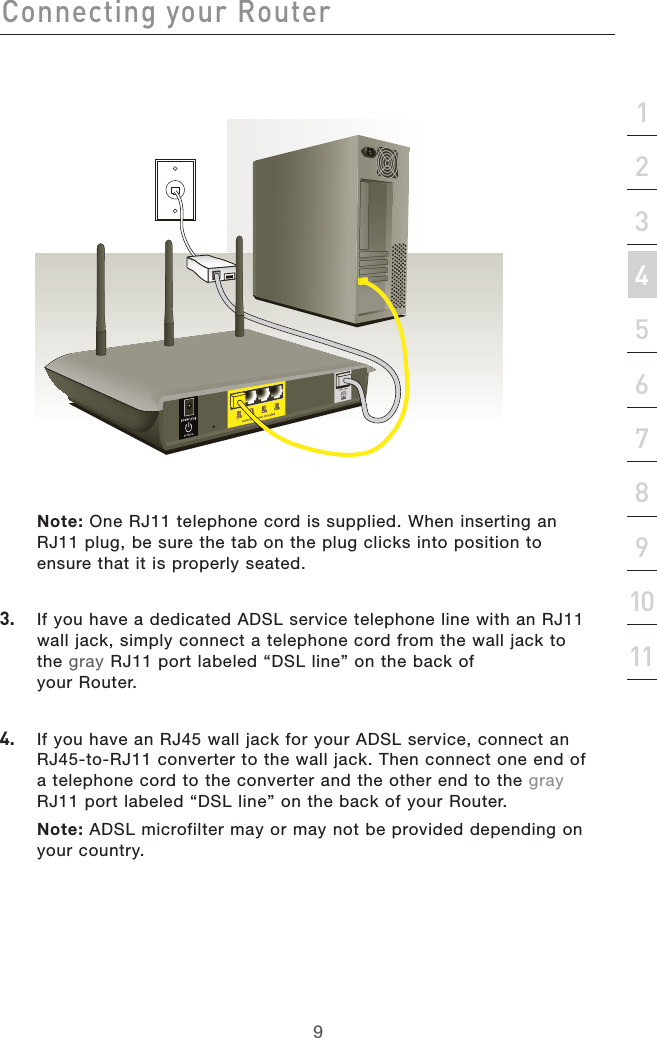
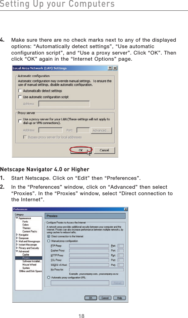
Contents
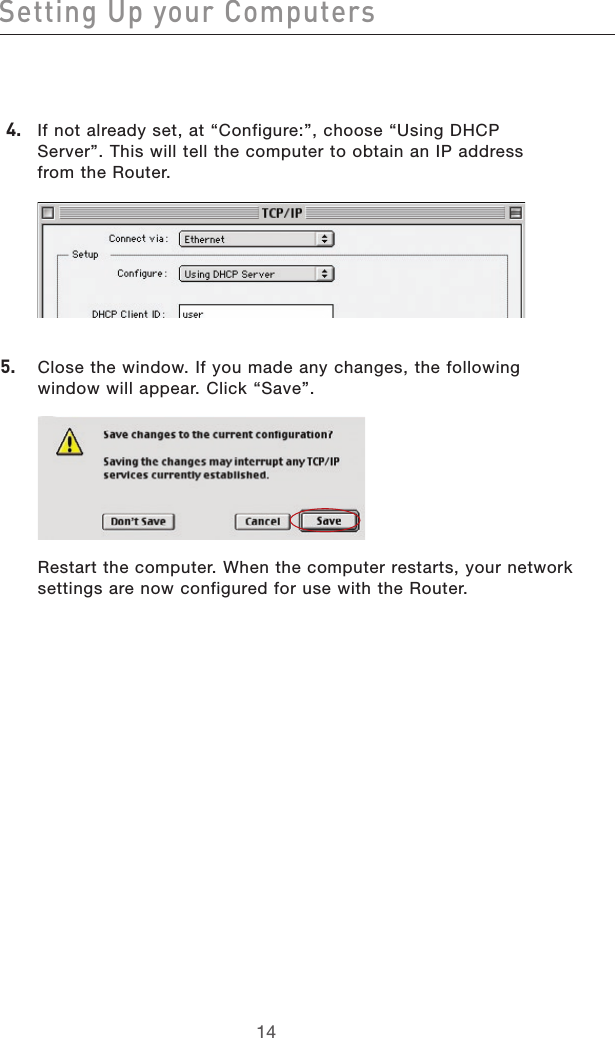
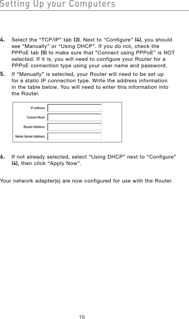
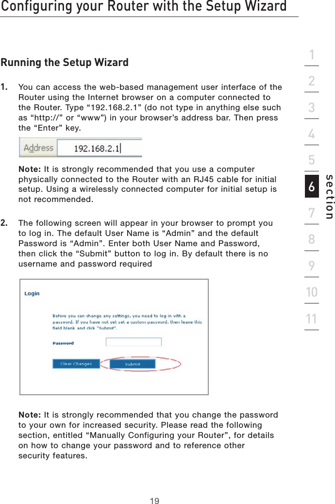
- 1. Manual 1
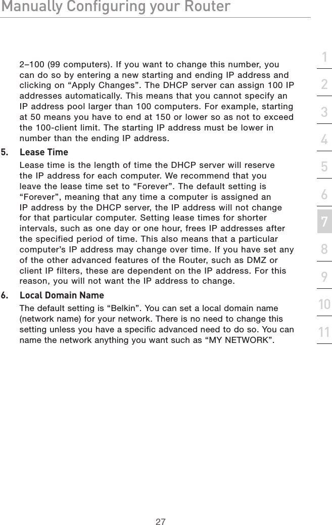
- 2. Manual 2
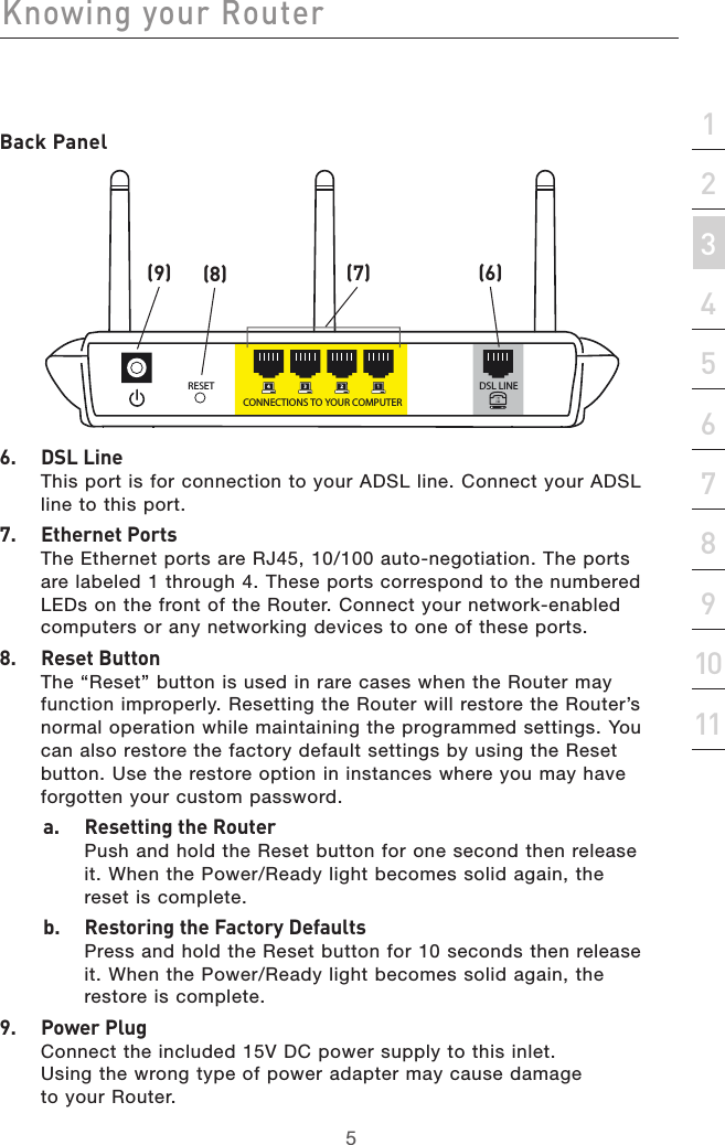
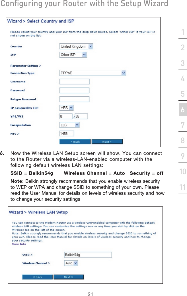
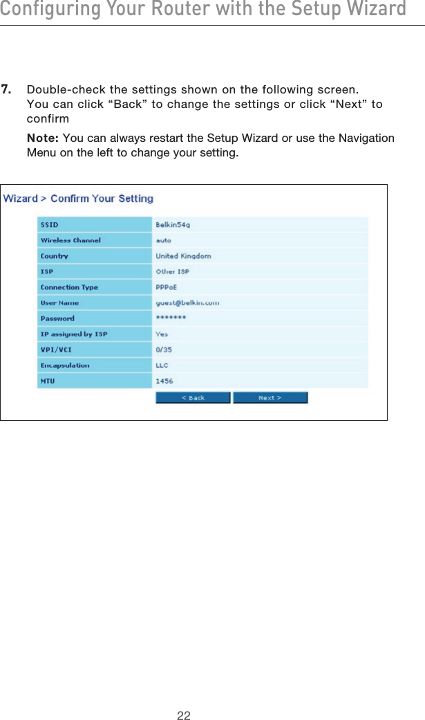
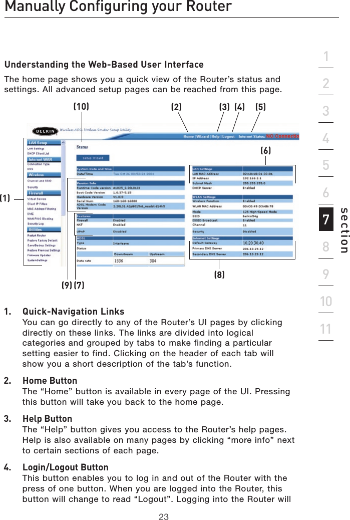
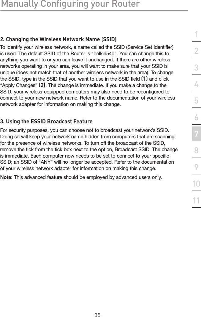
Manual 1