Belkin F5D8636A Belkin N Wireless Modem Router User Manual F5D8636 4 man updated by ARC
Belkin International, Inc. Belkin N Wireless Modem Router F5D8636 4 man updated by ARC
UserManual.wiki
>
Belkin
>
F5D8636A User Manual
Manual
Navigation menu
Upload a User Manual
Namespaces
Wiki Guide
HTML
PDF
Info
Views
User Manual
Discussion / Help
Navigation
![F5D8636-4_man updated by ARC Page 1 of 121 [Note from proofing: keep changes tracked at each revision, this is a uk manual] [insert title page per branding standard] [needs updated image] N Wireless Modem Router User Manual F5D8636-4 Splash Screen [update with new N background] [double check the page # and titles] Table of Contents 1 Introduction . . . . . . . . . . . . . . . . . . . . . . . . . . . . . . . . . . . . . .x Advantages of a Wireless Network Placement of your N Wireless Modem Router . . . . . . . . . . . . . . . . .x 2 Product Overview . . . . . . . . . . . . . . . . . . . . . . . . . . . . . . . . . .x Product Features . . . . . . . . . . . . . . . . . . . . . . . . . . . . . . . . .x 3 Knowing your Modem Router . . . . . . . . . . . . . . . . . . . . . . . . . . . . . . .x Package Contents . . . . . . . . . . . . . . . . . . . . . . . . . . . . . . . .x System Requirements . . . . . . . . . . . . . . . . . . . . . . . . . . . . .x Setup Assistant Software System Requirements . . . . . .x 4 Connecting and Configuring your Modem Router . . . . . . . . . . . . . . .x 5 Alternate Setup Method . . . . . . . . . . . . . . . . . . . . . . . . . . .x 6 Using the Web-Based Advanced User Interface . . . . . . . . . .x Changing LAN Settings . . . . . . . . . . . . . . . . . . . . . . . . . . .x Viewing the DHCP Client List Page . . . . . . . . . . . . . . . . . x Configuring the Wireless Network Settings . . . . . . . . . . . x Setting WPA Security. . . . . . . . . . . . . . . . . . . . . . . . . . . . . . . . . .x Setting WEP Encryption . . . . . . . . . . . . . . . . . . . . . . . . . . . . . . . . . .x Setting MAC Address Control . . . . . . . . . . . . . . . . . . . . . .x Configuring the Firewall . . . . . . . . . . . . . . . . . . . . . . . . . . x Using Dynamic DNS Utilities. . . . . . . . . . . . . . . . . . . . . . . . . . . . . . . . . . . x Restarting the Router . . . . . . . . . . . . . . . . . . . . . . . . . x Updating the Firmware . . . . . . . . . . . . . . . . . . . . . . . . x 7 Manually Configuring Network Settings . . . . . . .x 8 Recommended Web Browser Settings . . . . . . . . . . . . . . . . .x 9 Troubleshooting . . . . . . . . . . . . . . . . . . . . . . . . . . . . . . .x 10 Information . . . . . . . . . . . . . . . . . . . . . . . . . . . . . . . . . . .x](https://usermanual.wiki/Belkin/F5D8636A/User-Guide-977677-Page-1.png)
![F5D8636-4_man updated by ARC Page 3 of 121 [Introduction] Your Belkin N Wireless Modem Router uses a new smart-antenna technology called Multiple Input Multiple Output (MIMO). N MIMO complies with the IEEE draft 802.11n specification. It increases speed, range, reliability, and spectral efficiency for wireless networking systems. The element that makes Belkin’s N MIMO technology different from a conventional radio is the use of multiple antennas and two simultaneous data streams to deliver wireless transfers around your home or office. A conventional radio uses one antenna to transmit a data stream. Belkin’s N MIMO, on the other hand, uses two antennas. This design helps combat distortion and interference. Belkin’s N MIMO is multidimensional. It builds on one-dimensional smart-antenna technology by simultaneously transmitting two data streams through the same channel, which increases wireless capacity. Another element that enhances Belkin’s N MIMO is the use of aggregation as specified in the draft 802.11n specification. By shortening the space between packets and combining multiple smaller packets into one larger packet, Belkin’s N MIMO can transmit more data through available bandwidth. Think of conventional radio transmission as a two-lane highway. The speed limit governs the maximum allowable flow of traffic through that lane. Compared with conventional radios, one-dimensional smart antenna systems help move traffic through that lane faster and more reliably—analogous to a four-lane road on which traffic consistently moves at a rate closer to the speed limit. Belkin’s N MIMO helps traffic move at the speed limit and opens more lanes—to become the superhighway in this example. The rate of traffic flow is multiplied by the number of lanes that are opened. Revolutionary N Wireless Technology with MIMO (N MIMO)](https://usermanual.wiki/Belkin/F5D8636A/User-Guide-977677-Page-3.png)
![F5D8636-4_man updated by ARC Page 9 of 121 The Setup Assistant, second generation of Belkin’s renowned Easy Install Wizard, takes the guesswork out of setting up your Router. This automatic software determines your network settings for you and sets up the Router for connection to your Internet Service Provider (ISP). In a matter of minutes, your Router will be up and running on the Internet. Note: Setup Assistant software is compatible with Windows 2000, XP, and Vista, Mac OS X v10.4 and v10.5. If you are using another operating system, the Router can be set up using the Alternate Setup Method described in this User Manual (see page xx) [VERIFY PAGE NUMBER]. Integrated N Wireless Access Point N MIMO is an exciting new wireless technology based on the draft IEEE 802.11n specification. It employs MIMO (Multiple Input Multiple Output) smart-antenna technology that achieves data rates of up to 300Mbps.* Actual throughput is typically lower than the connected data rate and will vary depending on your networking environment. *NOTE: The standard transmission rate—300Mbps—is the physical data rate. Actual data throughput will be lower. MAC Address Filtering For added security, you can set up a list of MAC addresses (unique client identifiers) that are allowed access to your network. Every computer has its own MAC address. Simply enter these MAC addresses into a list using the Web-Based Advanced User Interface and you can control access to your network.](https://usermanual.wiki/Belkin/F5D8636A/User-Guide-977677-Page-9.png)

![F5D8636-4_man updated by ARC Page 12 of 121 Knowing your Router The Router has been designed to be placed on a desktop. All of the cables exit from the rear of the Router for better organization and utility. The Network Status Display is easily visible on the FRONT of the Router to provide you with information about network activity and status. See the Network Status Display Guide for more detailed information. [Reference only] A. Security [insert Lock Icon]](https://usermanual.wiki/Belkin/F5D8636A/User-Guide-977677-Page-12.png)
![F5D8636-4_man updated by ARC Page 13 of 121 OFF Wireless security is OFF Solid Blue Wireless security is ON Flashing Blue WPS sync is in progress B. Wireless-Computer Status [insert Laptop Icon] Off Wireless computer is not present Solid Blue Wireless computer is connected to the Router Blinking Amber Problem with wireless computer connecting properly to the Router C. Wired-Computer Status [Computer Icon] Off Wired computer is not present Solid Blue Wired computer is connected to the Router Blinking Amber Problem with wired computer connecting to the Router currently D. Router/Power Status [insert Router Icon] When you apply power to the Router or restart it, a short period of time elapses while the Router boots up. During this time, the “router” icon blinks. When the Router has completely booted up, the “router” icon becomes a solid light, indicating the Router is ready for use. Off Router is off Blinking Blue Router is booting up Solid Blue Router is on and ready E. ADSL Line Status [insert ADSL Icon] This icon lights in blue to indicate that your Router is connected properly to the ADSL. It turns amber when problem is detected. Off Router is NOT connected to a functioning ADSL line Blinking Blue Router is attempting to connect to the ADSL line Solid Blue Router is connected to an ADSL service and is functioning properly Blinking Amber Problem with ADSL line F. Internet Status [insert Globe Icon]](https://usermanual.wiki/Belkin/F5D8636A/User-Guide-977677-Page-13.png)
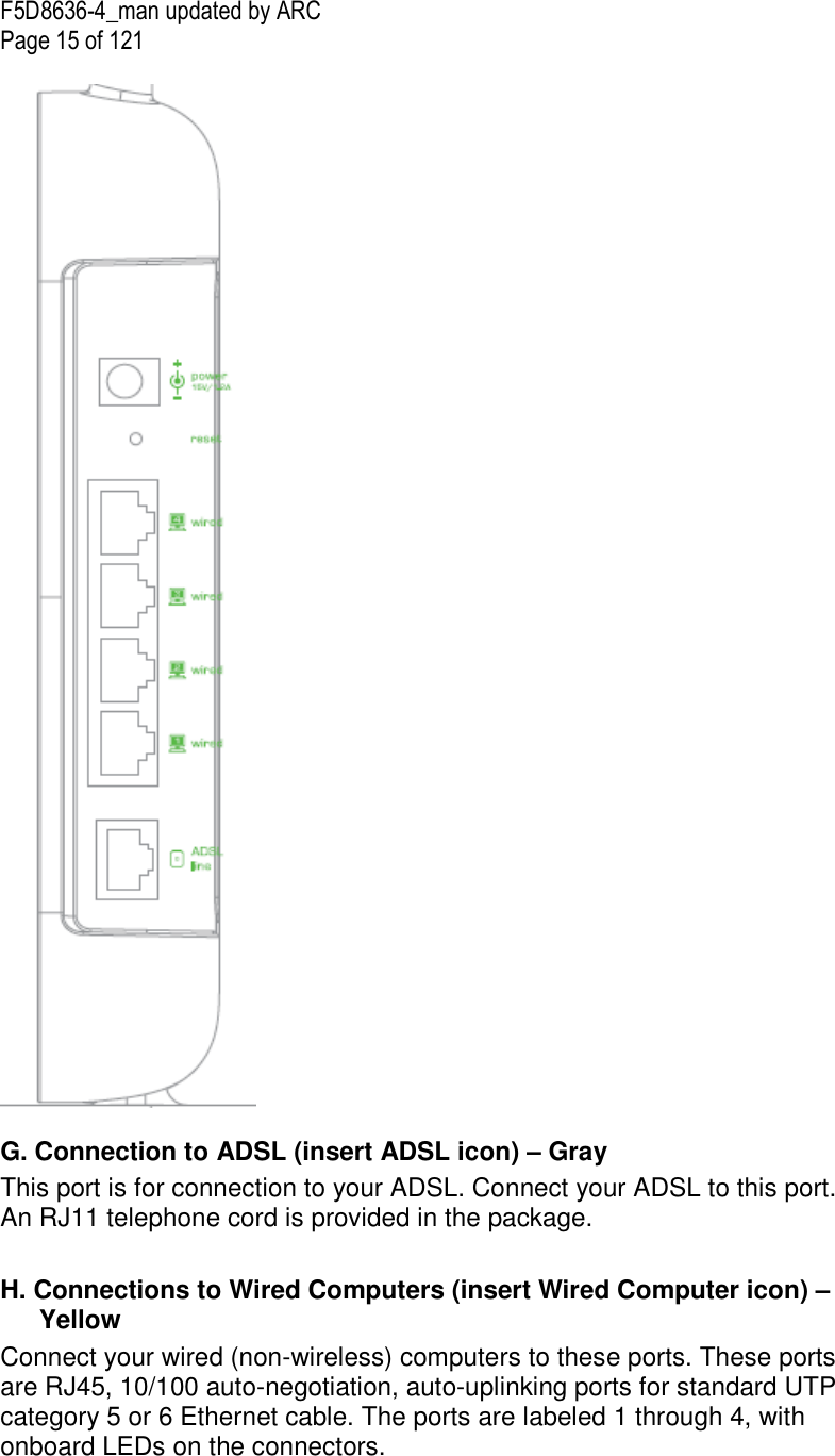
![F5D8636-4_man updated by ARC Page 14 of 121 This unique icon shows you when the Router is connected to the Internet. When the light is off, the Router is NOT connected to the Internet. When the light is blinking amber, the Router is attempting to connect to the Internet. When the light is solid blue, the Router is connected to the Internet. When using the “Disconnect after x minutes” feature, this icon becomes extremely useful in monitoring the status of your Router’s connection. Off Router is NOT connected to the Internet Blinking Blue Router is attempting to connect to the Internet Solid Blue Router is connected to the Internet Blinking Amber Router is not connected to the Internet [insert router rear-panel line art with H to K line up to the ports, below is an example for reference only]](https://usermanual.wiki/Belkin/F5D8636A/User-Guide-977677-Page-14.png)
![F5D8636-4_man updated by ARC Page 17 of 121 Setup Assistant Belkin has provided our Setup Assistant software to make installing your Router a simple and easy task. You can use it to get your Router up and running in minutes. The Setup Assistant requires that your Windows 2000 or XP computer be connected directly to your ADSL and that the Internet connection is active and working at the time of installation. If it is not, you must use the “Alternate Setup Method” section of this User Manual to configure your Router. Additionally, if you are using an operating system other than Windows 2000, XP, or Vista, or Mac OS X v10.4 and v10.5, you must set up the Router using the “Alternate Setup Method” section of this User Manual. Step 1: Hardware Connections 1.1 Brand-New Setup Follow these steps if you are not replacing an existing modem. If you are replacing an existing modem, skip to the next section, “Replacing an Existing Modem or Modem Router”, starting on page 20. (verify the page number) A. Unpack your new Router from the box and place it next to your computer. Raise the Router’s antennas. [insert line art from QIG] (Modem Router illustrate needs to be modified.) B. Retrieve the yellow RJ45 cable that was included with your Router. First, connect one end to any yellow port labeled “Wired” on the back of your Router. Then, connect the other end to the networking](https://usermanual.wiki/Belkin/F5D8636A/User-Guide-977677-Page-17.png)
![F5D8636-4_man updated by ARC Page 18 of 121 port on the back of your computer. [Insert Ethernet logo] [insert line art from QIG] (Modem Router illustrate needs to be modified.) C. Retrieve the included gray RJ11 phone cord. Connect one end to the gray port labeled “ADSL line” on the back of your Router. Then connect the other end to your ADSL connection (either a wall jack or an ADSL splitter). [insert line art from QIG] (Modem Router illustrate needs to be modified.) Note: Some ADSL connections require a micro filter. Your ADSL provider can tell you if you need one. Belkin includes a micro filter in regions known to use them. You may or may not have received one in your box. D. Plug your Router’s power supply into the black port labeled “Power” on the back of your Router. [insert line art from QIG]](https://usermanual.wiki/Belkin/F5D8636A/User-Guide-977677-Page-18.png)
![F5D8636-4_man updated by ARC Page 19 of 121 (Modem Router illustrate needs to be modified.) E. Wait 20 seconds for the Router to start up. Look at the display on the front of the Router. Make sure the “Wired” and “Router” icons are lit up in blue. If they are not, recheck your connections. [insert line art from QIG] (Modem Router illustrate needs to be modified.) 1.2 Replacing an Existing Modem or Modem Router Follow these steps if you currently have a modem or a modem router that you will be replacing with your new Router. Important: Please unplug the power adapter of your old modem from your wall outlet first. A. Unpack your new Router from the box and place it next to your old modem. Raise the Router’s antennas. Unplug your old modem’s power cord. [insert line art from QIG]](https://usermanual.wiki/Belkin/F5D8636A/User-Guide-977677-Page-19.png)
![F5D8636-4_man updated by ARC Page 20 of 121 (Modem Router illustrate needs to be modified.) B. Locate the cable that connects your old modem to your computer. Unplug that cable from your old modem, and plug it into any yellow port labeled “Wired” on the back of your new Router. [insert line art from QIG] (Modem Router illustrate needs to be modified.) C. Locate the cable that connects your old modem to the ADSL wall jack. Unplug it from your old modem and then connect it to the gray port labeled “ADSL line” on the back of your Router. [insert line art from QIG] (Modem Router illustrate needs to be modified.)](https://usermanual.wiki/Belkin/F5D8636A/User-Guide-977677-Page-20.png)
![F5D8636-4_man updated by ARC Page 21 of 121 D. Plug your Router’s power supply into the black port labeled “Power” on the back of your Router. [insert lineart from QIG] (Modem Router illustrate needs to be modified.) E. Wait 20 seconds for the Router to start up. Look at the display on the front of the Router. Make sure the “Wired” and “Router” icons are lit in blue. If they are not, recheck your connections. [insert lineart from QIG] (Modem Router illustrate needs to be modified.) Step 2: Set Up the Router – Run the Setup Assistant Software A. Shut down any programs that are running on your computer at this time. Turn off any firewall or Internet-connection-sharing software on your computer. B. Insert the CD into your computer. The Setup Assistant will automatically appear on your computer’s screen within 15 seconds. Click on “Setup Assistant” to run the Setup Assistant. Follow the instructions there. [insert lineart from QIG]](https://usermanual.wiki/Belkin/F5D8636A/User-Guide-977677-Page-21.png)
![F5D8636-4_man updated by ARC Page 22 of 121 (Modem Router illustrate needs to be modified.) [Note, all EZI screenshots are updated] <Insert: EZI1.tif> Note for Windows Users: If the Setup Assistant does not start up automatically, select your CD-ROM drive from “My Computer” and double-click on the file named “SetupAssistant” to start the Setup Assistant. IMPORTANT: Run the Setup Assistant from the computer that is directly connected to the Router from Step 1.1B.](https://usermanual.wiki/Belkin/F5D8636A/User-Guide-977677-Page-22.png)
![F5D8636-4_man updated by ARC Page 23 of 121 Select Country Select your country from the drop-down box. Click “Begin” to continue. [insert EZI2b.tif] Confirmation Screen Verify that you have completed all QIG steps by checking the box to the right of the arrow. Click “Next” to continue. [insert EZI3.tif]](https://usermanual.wiki/Belkin/F5D8636A/User-Guide-977677-Page-23.png)
![F5D8636-4_man updated by ARC Page 24 of 121 Progress Screen Setup Assistant will show you a progress screen each time a step in the setup has been completed. [insert EZI4.tif]](https://usermanual.wiki/Belkin/F5D8636A/User-Guide-977677-Page-24.png)
![F5D8636-4_man updated by ARC Page 25 of 121 2.1 Checking Settings The Setup Assistant will now examine your computer’s network settings and gather information needed to complete the Router’s connection to the Internet. [insert EZI5.tif] 2.2 Verifying Hardware Connections The Setup Assistant will now verify your hardware connection. [insert EZI6.tif]](https://usermanual.wiki/Belkin/F5D8636A/User-Guide-977677-Page-25.png)
![F5D8636-4_man updated by ARC Page 26 of 121 2.3 Naming your Wireless Network The Setup Assistant will display the default wireless network name or Service Set Identifier (SSID). This is the name of your wireless network to which your computers or devices with wireless network adapters will connect. You can either use the default or change it to something unique. Write down this name for future reference. If the Router is capable of “High Speed Mode”, this option will be checked. You can turn off this option later using the Bandwidth Switch described in this User Manual (see page 48) [match page # to “Using the Bandwidth Switch” paragraph under the Wireless section]. Click “Next” to continue. [insert EZI8.tif]](https://usermanual.wiki/Belkin/F5D8636A/User-Guide-977677-Page-26.png)
![F5D8636-4_man updated by ARC Page 27 of 121 2.4 Requesting Internet Account Info (if needed) Select your ISP from the drop-down boxes. [insert EZI10.tif]](https://usermanual.wiki/Belkin/F5D8636A/User-Guide-977677-Page-27.png)
![F5D8636-4_man updated by ARC Page 28 of 121 Note to US model owner: To comply with US FCC regulation, the country selection function has been completely removed from all US models. The above function is for non-US models only. If your Internet account requires a login and password, you will be prompted with a screen similar to the illustration below. Click “Next” to continue. [insert EZI11.tif] 2.5 Configuring the Router The Setup Assistant will now configure your Router by sending data to the Router and restarting it. Wait for the on-screen instructions. Note: Do not disconnect any cable or power off the Router while the Router is rebooting. Doing so will render your Router inoperable. [insert EZI12.tif]](https://usermanual.wiki/Belkin/F5D8636A/User-Guide-977677-Page-28.png)
![F5D8636-4_man updated by ARC Page 29 of 121 2.6 Checking Internet Connection We are almost done. The Setup Assistant will now check your connection to the Internet. [insert EZI14.tif]](https://usermanual.wiki/Belkin/F5D8636A/User-Guide-977677-Page-29.png)
![F5D8636-4_man updated by ARC Page 30 of 121 Congratulations You have finished installing your new Belkin Router. You will see the Congratulations screen when your Router can connect to the Internet. You can begin surfing by opening your browser and going to any website. You can use the Setup Assistant to set up your other wired and wireless computers to connect to the Internet by clicking “Next”. If you decide to add computers to your Router later, select “Finish—return to Main Menu” and then click “Next”. [insert EZI20.tif] Troubleshooting If the Setup Assistant is not able to connect to the Internet, you will see the following screen. Follow the on-screen instructions to go through the troubleshooting steps. [insert EZI15.tif]](https://usermanual.wiki/Belkin/F5D8636A/User-Guide-977677-Page-30.png)
![F5D8636-4_man updated by ARC Page 31 of 121 2.7 Optional: Assistance Connecting Other Computers This optional step will help you to connect additional wired and wireless computers to your network. Follow the on-screen instructions. [insert EZI23.tif]](https://usermanual.wiki/Belkin/F5D8636A/User-Guide-977677-Page-31.png)
![F5D8636-4_man updated by ARC Page 32 of 121 Once you have verified that your other wired and wireless computers are properly connected, your network is set up and working. You can now surf the Internet. Click “Next” to return to the main menu. [insert EZI24.tif]](https://usermanual.wiki/Belkin/F5D8636A/User-Guide-977677-Page-32.png)
![F5D8636-4_man updated by ARC Page 33 of 121 Step 3: Set Up Wireless Security – Run the Security Assistant Software Now that your network is set up and working, it is recommended that you turn on wireless security to prevent unauthorized access to your network from neighboring wireless-enabled computers. The Security Assistant will guide you through the process. Click “Security Assistant” and follow the on-screen instructions. [Insert EZI25.tif] [Circle “Security Assistant”] Progress Screen The Security Assistant will show you a progress screen each time a step has been completed. [insert EZI28.tif] IMPORTANT: Run the Setup Assistant from the computer that is directly connected to the Router from Steps 1.1B and 1.2B.](https://usermanual.wiki/Belkin/F5D8636A/User-Guide-977677-Page-33.png)
![F5D8636-4_man updated by ARC Page 34 of 121 3.1 Picking the Security Type Select the security type for your wireless network and click “Next” to continue. [insert EZI30.tif]](https://usermanual.wiki/Belkin/F5D8636A/User-Guide-977677-Page-34.png)
![F5D8636-4_man updated by ARC Page 35 of 121 3.2 Creating a Network Key Enter a network key (PSK) for your wireless network and click “Next” to continue. [Insert EZI31.tif] 3.3 Transferring the Key After setting up your wireless security, you will have to transfer the network key to each of your wireless computers. Click on “Transfer Key” if you have a USB flash drive. Follow the on-screen instructions, or click on “Print” to print the information. Manually enter it to each wireless computer. Then, click “Next” to continue. [insert EZI33.tif]](https://usermanual.wiki/Belkin/F5D8636A/User-Guide-977677-Page-35.png)
![F5D8636-4_man updated by ARC Page 36 of 121 3.4 Verifying the Connection If all your wireless computers are able to connect to the Router, click “Next”. If you are having trouble, select “I had problem with at least one computer” and click “Next”. Then, follow on-screen instructions. [insert EZI36.tif] Congratulations](https://usermanual.wiki/Belkin/F5D8636A/User-Guide-977677-Page-36.png)
![F5D8636-4_man updated by ARC Page 37 of 121 Once you have verified that your wireless computers are properly connected, your wireless network is set up and secured. You now can run your network wirelessly and securely. Click “Finish” to take you back to the main menu. [insert EZI37.tif] Alternate Setup Method Step 1: Hardware Connections – Follow the Quick Installation Guide See the QIG or Step 1: Hardware Connections from the previous section. Step 2: Set your Computer’s Network Settings to Work with a DHCP Server See the section in this User Manual called “Manually Configuring Network Settings” for directions.](https://usermanual.wiki/Belkin/F5D8636A/User-Guide-977677-Page-37.png)
![F5D8636-4_man updated by ARC Page 38 of 121 Step 3: Configuring the Router Using the Web-Based Advanced User Interface Using your Internet browser, you can access the Router’s Web-Based Advanced User Interface. In your browser, type “192.168.2.1” (do not type in anything else such as “http://” or “www”). Then press the “Enter” key. [insert IP_Address.tif] Logging into the Router You will see the Router’s home page in your browser window. The home page is visible to any user who wants to see it. To make any changes to the Router’s settings, you have to log in. Clicking the “Login” button or clicking on any one of the links on the home page will take you to the login screen. The Router ships with no password entered. In the login screen, leave the password blank and click the “Submit” button to log in. [FW01.tif]](https://usermanual.wiki/Belkin/F5D8636A/User-Guide-977677-Page-38.png)
![F5D8636-4_man updated by ARC Page 39 of 121 Logging out of the Router One computer at a time can log into the Router for the purposes of making changes to the settings of the Router. Once a user has logged in to make changes, there are two ways that the computer can be logged out. Clicking the “Logout” button will log the computer out. The second method is automatic. The login will time out after a specified period of time. The default login time-out is 10 minutes. This can be changed from one to 99 minutes. For more information, see the section in this manual titled “Changing the Login Time-Out Setting”. Understanding the Web-Based Advanced User Interface The home page is the first page you will see when you access the Advanced User Interface (UI). The home page shows you a quick view of the Router’s status and settings. All advanced setup pages can be reached from this page. [FW02.tif] 1. Quick-Navigation Links You can go directly to any of the Router’s advanced UI pages by clicking directly on these links. The links are divided into logical categories and grouped by tabs to make finding a particular setting easier to find. Clicking on the purple header of each tab will show you a short description of the tab’s function. (2) (5) (3) (4) (9) (10)](https://usermanual.wiki/Belkin/F5D8636A/User-Guide-977677-Page-39.png)
![F5D8636-4_man updated by ARC Page 42 of 121 13. Page Name The page you are on can be identified by this name. This User Manual will sometimes refer to pages by name. For instance “LAN > LAN Settings” refers to the “LAN Settings” page. Step 4: Configuring your Router for Connection to your Internet Service Provider (ISP) The “Internet/WAN” tab is where you will set up your Router to connect to your Internet Service Provider (ISP). The Router is capable of connecting to virtually any ISP’s system provided you have correctly configured the Router’s settings for your ISP’s connection type. Your ISP connection settings are provided to you by your ISP. To configure the Router with the settings that your ISP gave you, click “Connection Type” (A) on the left side of the screen. Select the connection type you use. If your ISP gave you DNS settings, clicking “DNS” (B) allows you to enter DNS address entries for ISPs that require specific settings. Clicking “MAC Address” (C) will let you clone your computer’s MAC address or type in a specific WAN MAC address, if required by your ISP. When you have finished making settings, the “Internet Status” indicator will read “connection OK” if your Router is set up properly. [FW03.tif] Connection Type From the “Connection Type” page, you can select one of these five connection types based on the instruction provided by your ISP: (A) (B) (C)](https://usermanual.wiki/Belkin/F5D8636A/User-Guide-977677-Page-42.png)
![F5D8636-4_man updated by ARC Page 43 of 121 • PPPoE • PPPoA • Dynamic/Fixed IP (1483 Bridged) • Static IP (IPoA) • Modem Only (Disable Internet Sharing) Select the type of connection you use by clicking the radio button (1) next to your connection type and then clicking “Next”. [FW04.tif] Setting your ISP Connection Type to PPPoE or PPPoA PPPoE (Point-to-Point Protocol over Ethernet) is the standard method of connecting networked devices. It requires a user name and password to access the network of your ISP for connecting to the Internet. PPPoA (PPP over ATM) is similar to PPPoE, but is mostly implemented in the UK. Select PPPoE or PPPoA and click “Next”. Then enter the information provided by your ISP, and click “Apply Changes” to activate your settings.](https://usermanual.wiki/Belkin/F5D8636A/User-Guide-977677-Page-43.png)
![F5D8636-4_man updated by ARC Page 44 of 121 [FW05.tif] 1. User Name - Enter the user name. (Assigned by your ISP). 2. Password - Enter your password. (Assigned by your ISP). 3. Retype Password - Confirm the password. (Assigned by your ISP). 4. Service Name (Optional) - A service name is rarely required by an ISP. If you are not sure if your ISP requires a service name, leave this blank. 5. IP assigned by ISP 1) For the Dynamic IP connection - Select “Yes” if your ISP instructed you to use Dynamic IP. 2) For the Static IP connection – Select “No” if your ISP instructed you to use Static IP. - IP Address – Enter an IP address assigned by your ISP for the Router WAN interface. (FW05-1.tif) 6. VPI/VCI - Enter your Virtual Path Identifier (VPI) and Virtual Circuit Identifier](https://usermanual.wiki/Belkin/F5D8636A/User-Guide-977677-Page-44.png)
![F5D8636-4_man updated by ARC Page 46 of 121 [FW06.tif] For Dynamic IP connection: 1. IP assigned by ISP – Select “Yes” if your ISP instructed you to use Dynamic IP. 2. VPI/VCI - Enter your Virtual Path Identifier (VPI) and Virtual Circuit Identifier (VCI) parameter here. These identifiers are assigned by your ISP. 3. Encapsulation - Select LLC or VC MUX your ISP uses. Click “Apply Changes” to save and activate your settings. To go back to the original settings before saving, click “Clear Changes”; or click any of the Quick-Navigation links for other options. Your new settings will not be saved unless you click “Apply Changes”.](https://usermanual.wiki/Belkin/F5D8636A/User-Guide-977677-Page-46.png)
![F5D8636-4_man updated by ARC Page 47 of 121 [FW07.tif] For Static IP connection: 1. IP assigned by ISP – Select “No” if your ISP instructed you to use fixed IP. 2. IP Address – Enter an IP address assigned by your ISP for the Router WAN interface. 3. Subnet Mask – Enter a subnet mask assigned by your ISP. 4. Default Gateway – Enter a default gateway IP address assigned by your ISP. 5. VPI/VCI – Enter your Virtual Path Identifier (VPI) and Virtual Circuit Identifier (VCI) parameters here. These identifiers are assigned by your ISP. 6. Encapsulation – Select the LLC or VC MUX your ISP uses. Click “Apply Changes” to save and activate your settings. To go back to the original settings before saving, click “Clear Changes”. Or click any of the Quick-Navigation links for other options. Your new settings will not be saved unless your click “Apply Changes”.](https://usermanual.wiki/Belkin/F5D8636A/User-Guide-977677-Page-47.png)
![F5D8636-4_man updated by ARC Page 48 of 121 Setting your ISP Connection Type to Static IP (IPoA) This connection type is also called “Classical IP over ATM” or “CLIP”, which your ISP provides a fixed IP for your Router to connect to the Internet. [FW08.tif] 1. WAN IP Address – Enter an IP address assigned by your ISP for the Router WAN interface. 2. Subnet Mask - Enter a subnet mask assigned by your ISP. 3. Use Static Default Gateway - Enter a default gateway IP address. If the Router cannot find the destination address within its local network, it will forward the packets to the default gateway assigned by your ISP. 4. VPI/VCI - Enter your Virtual Path Identifier (VPI) and Virtual Circuit Identifier (VCI) parameter here. These identifiers are assigned by your ISP. 5. Encapsulation - Select LLC or VC MUX your ISP uses. Click “Apply Changes” to save and activate your settings. To go back to the original settings before saving, click “Clear Changes”. Or click any of the Quick-Navigation links for other options. Your new settings will not be saved unless your click “Apply Changes”. Setting your Connection Type to Modem Only (Disable Internet Sharing) In this mode, the Router simply acts as a bridge passing packets across the DSL port. It requires additional software to be installed on your computers in order to access the Internet.](https://usermanual.wiki/Belkin/F5D8636A/User-Guide-977677-Page-48.png)
![F5D8636-4_man updated by ARC Page 49 of 121 [FW09.tif] 1. Enable Bridge Service – Check this box to enable bridge service 2. VPI/VCI – Enter your Virtual Path Identifier (VPI) and Virtual Circuit Identifier (VCI) parameters here. (Assigned by your ISP). 3. Encapsulation – Select the LLC or VC MUX your ISP uses. Click “Apply Changes” to save and activate your settings. To go back to the original settings before saving, click “Clear Changes”. Or click any of the Quick-Navigation links for other options. Your new settings will not be saved unless your click “Apply Changes”. Setting Custom Domain Name Server (DNS) Settings A “Domain Name Server” is a server located on the Internet that translates Universal Resource Locaters (URLs) like “www.belkin.com” to IP addresses. Many Internet Service Providers (ISPs) do not require you to enter this information into the Router. The “Automatic from ISP” box (1) should be checked if your ISP did not give you a specific DNS address. If you are using a static IP connection type, then you may need to enter a specific DNS address and secondary DNS address for your connection to work properly. If your connection type is dynamic or PPPoE, it is likely that you do not have to enter a DNS address. Leave the “Automatic from ISP” box checked. To enter the DNS address settings, uncheck the “Automatic from ISP” box and enter your DNS entries in the spaces provided. Click “Apply Changes” (2) to save the settings.](https://usermanual.wiki/Belkin/F5D8636A/User-Guide-977677-Page-49.png)
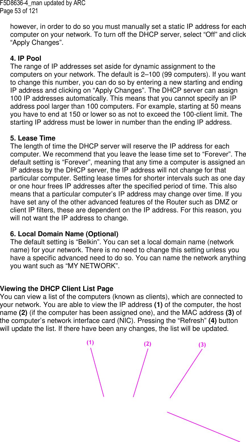
![F5D8636-4_man updated by ARC Page 50 of 121 [FW10.tif] Using the Web-Based Advanced User Interface Using your Internet browser, you can access the Router’s Web-Based Advanced User Interface. In your browser, type “192.168.2.1” (do not type in anything else such as “http://” or “www”) then press the “Enter” key. [insert IP_Address.tif] Use the same screenshot You will see the Router’s home page in your browser window. Viewing the LAN Settings Clicking on the header of the LAN tab (1) will take you to the LAN tab’s header page. A quick description of the functions can be found here. To view the settings or make changes to any of the LAN settings, click on “LAN Settings” (2) or to view the list of connected computers, click on “DHCP client list” (3). (1) (2) (1) (2) (3)](https://usermanual.wiki/Belkin/F5D8636A/User-Guide-977677-Page-50.png)
![F5D8636-4_man updated by ARC Page 51 of 121 [FW11.tif]](https://usermanual.wiki/Belkin/F5D8636A/User-Guide-977677-Page-51.png)
![F5D8636-4_man updated by ARC Page 52 of 121 Changing LAN Settings All settings for the internal LAN setup of the Router can be viewed and changed here. [FW12.tif] 1. IP Address The “IP address” is the internal IP address of the Router. The default IP address is “192.168.2.1”. To access the advanced setup interface, type this IP address into the address bar of your browser. This address can be changed if needed. To change the IP address, type in the new IP address and click “Apply Changes”. The IP address you choose should be a non-routable IP. Examples of a non-routable IP are: 192.168.x.x (where x is anything between 0 and 255) 10.x.x.x (where x is anything between 0 and 255) 2. Subnet Mask There is no need to change the subnet mask. This is a unique, advanced feature of your Belkin Router. It is possible to change the subnet mask if necessary; however, do NOT make changes to the subnet mask unless you have a specific reason to do so. The default setting is “255.255.255.0”. 3. DHCP Server The DHCP server function makes setting up a network very easy by assigning IP addresses to each computer on the network automatically. The default setting is “On”. The DHCP server can be turned OFF if necessary; (2) (3) (4) (5) (6) (1)](https://usermanual.wiki/Belkin/F5D8636A/User-Guide-977677-Page-52.png)
![F5D8636-4_man updated by ARC Page 54 of 121 [FW13.tif] Configuring the Wireless Network Settings The “Wireless” tab lets you make changes to the wireless network settings. From this tab you can make changes to the wireless network name or Service Set Identifier (SSID), operating channel, encryption security settings, and configure the Router to be used as an access point. Changing the Wireless Network Name (SSID) To identify your wireless network, a name called the SSID is used. The SSID is your network name. The default network name of the Router is “Belkin_N_ADSL_” followed by six digits that are unique to your Router. Your network name will look something like “Belkin_N_ADSL_123456”. You can change this to anything you choose, or you can leave it unchanged. Keep in mind, if you decide to change your wireless network name, and there are other wireless networks operating in your area, your network name needs to be different from other wireless networks that may be operating in your area. To change the SSID, type in the SSID that you want to use in the SSID field (1) and click “Apply Changes” (2). The change is immediate. If you make a change to the SSID, your wireless-equipped computers may also need to be reconfigured to connect to your new network name. Refer to the documentation of your wireless network adapter for information on making this change. (1)](https://usermanual.wiki/Belkin/F5D8636A/User-Guide-977677-Page-54.png)
![F5D8636-4_man updated by ARC Page 55 of 121 [FW14.tif] Note: Please periodically check for new Router firmware updates from the “Utilities > Firmware update” page. Newer firmware can fix problems, add wireless features, and/or improve wireless performance (see page 69). [Designer, Please match page number to the firmware update section] Changing the Wireless Channel There are a number of operating channels from which you can choose—in the United Kingdom (and most of Europe), Australia, and most of Asia, there are 13. In other countries, there are other channel requirements. Your Router is configured to operate on the proper channels for the country in which you reside. The channel can be changed if needed. If there are other wireless networks operating in your area, your network should be set to operate on a channel that is different than the other wireless networks. Extension Channel The IEEE 802.11n draft specification allows the use of a secondary channel to double the bandwidth (see the “Using the Bandwidth Switch” section on the next page). An appropriate extension channel will be displayed when operating in 40MHz mode (see the “Using the Wireless Mode Switch” section below). The channel can be changed if necessary.](https://usermanual.wiki/Belkin/F5D8636A/User-Guide-977677-Page-55.png)
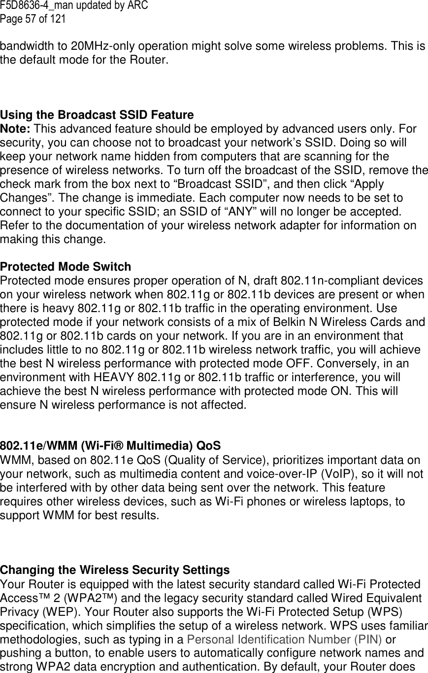
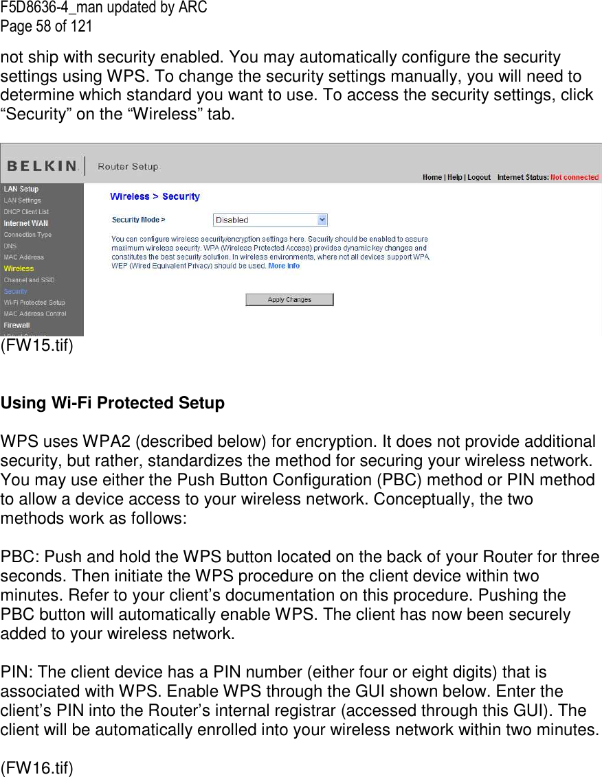
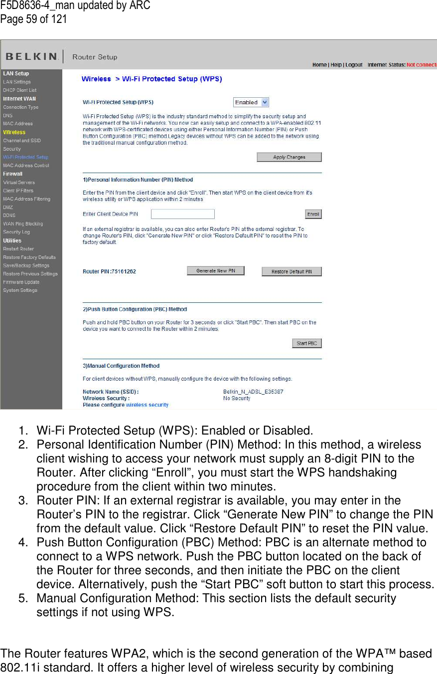
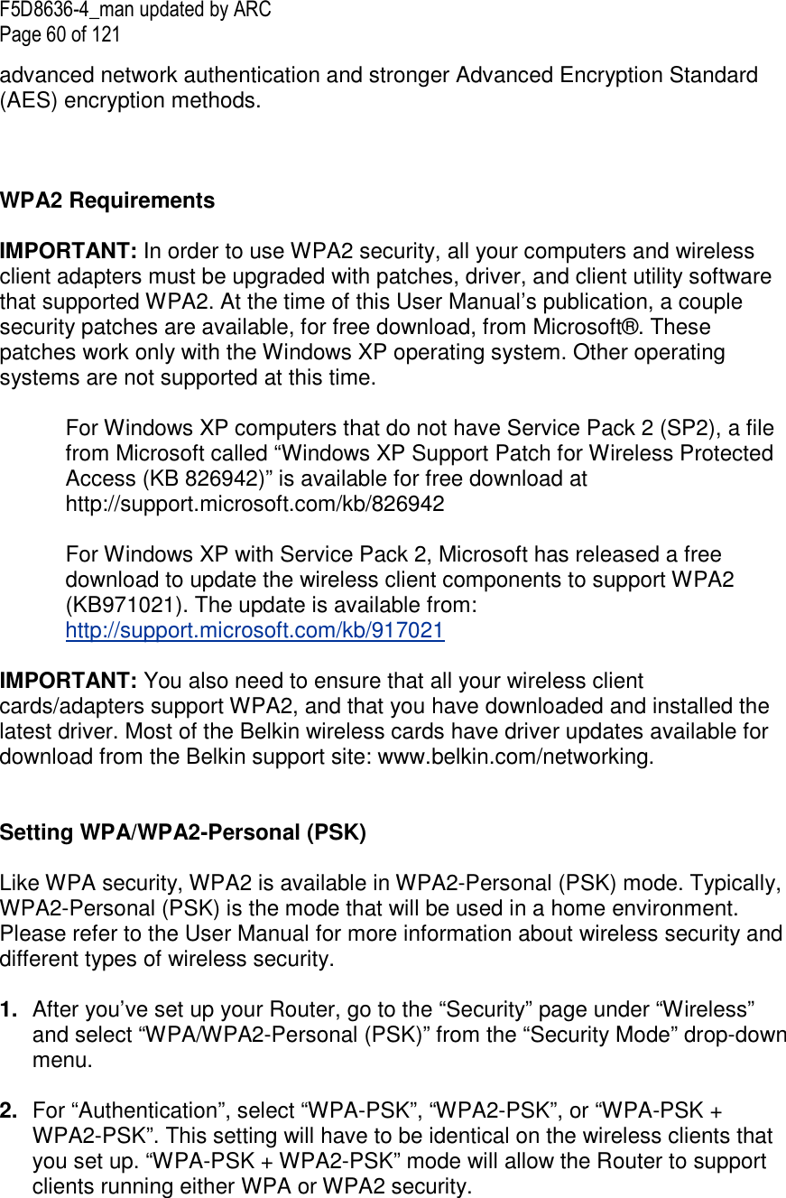
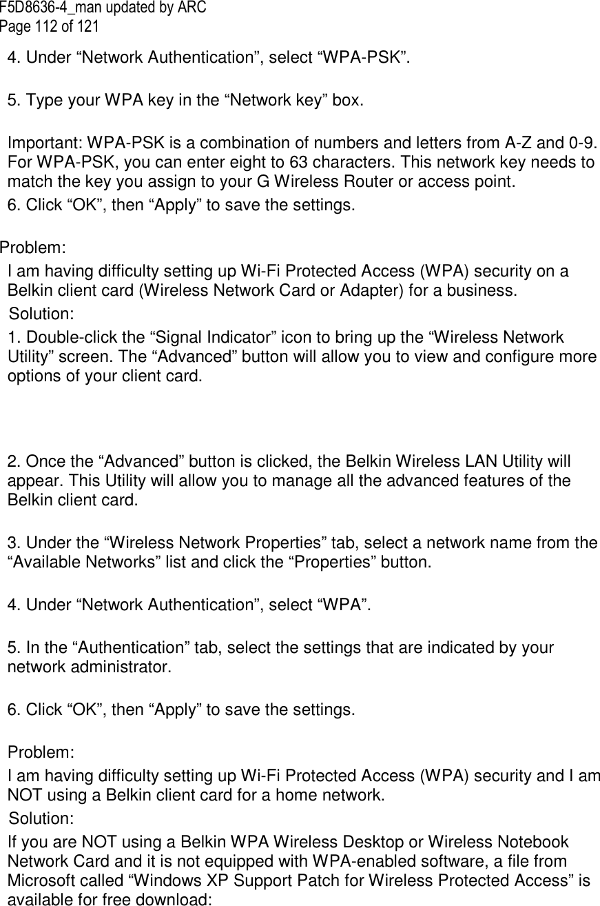
![F5D8636-4_man updated by ARC Page 61 of 121 3. For “Encryption Technique”, select “TKIP”, “AES”, or “TKIP+AES”. This setting will have to be identical on the wireless clients that you set up. 4. Enter your pre-shared key (PSK). This can be from eight to 63 characters and can be letters, numbers, or symbols. This same key must be used on all of the wireless clients that you set up. For example, your PSK might be something like: “Smith family network key”. Click “Apply Changes” to finish. You must now set all wireless clients to match these settings. [FW17.tif] IMPORTANT: Make sure your wireless computers are updated to work with WPA2 and have the correct settings to get proper connection to the Router. Setting WPA Security Note: To use WPA security, your wireless network cards must be equipped with software that supports WPA. At the time this User Manual was published, a security patch from Microsoft is available for free download. This patch works only with Windows XP. Your Router supports WPA-PSK. WPA-PSK uses what is known as a pre-shared key as the security key. A pre-shared key is basically a password that is between eight and 39 characters long. It can be a combination of letters, numbers, or characters. Each client uses the same key to access the network. Typically this is the mode that will be used in a home environment. Setting WPA-PSK](https://usermanual.wiki/Belkin/F5D8636A/User-Guide-977677-Page-61.png)
![F5D8636-4_man updated by ARC Page 62 of 121 1. From the “Security Mode” drop-down menu, select “WPA-PSK”. 2. For “Encryption Technique”, select “TKIP” or “AES”. This setting will have to be identical on the clients that you set up. 3. Enter your pre-shared key. This can be from eight to 39 characters and can be letters, numbers, or symbols. This same key must be used on all of the clients that you set up. 4. Click “Apply Changes” to finish. You must now set all clients to match these settings. [FW18.tif] Setting WEP Encryption Note to Mac users: The “Passphrase” option will not operate with Apple® AirPort®. To configure encryption for your Mac computer, set the encryption using the manual method described in the next section. 1. Select “128-bit WEP” or “64-bit WEP” from the drop-down menu. 2. After selecting your WEP encryption mode, you can enter you WEP key manually by typing in the hex WEP key manually, or you can type a passphrase in the “PassPhrase” field and click “Generate” to create a WEP key from the passphrase. Click “Apply Changes” to finish. You must now set all of your clients to match these settings.](https://usermanual.wiki/Belkin/F5D8636A/User-Guide-977677-Page-62.png)
![F5D8636-4_man updated by ARC Page 63 of 121 [FW19.tif] 3. Encryption in the Router is now set. Each of your computers on your wireless network will now need to be configured with the same passphrase. Refer to the documentation of your wireless network adapter for information on making this change. Using a Hexadecimal Key A hexadecimal key is a mixture of numbers and letters from A–F and 0–9. 64-bit keys are 10 digits long and can be divided into five two-digit numbers. 128-bit keys are 26 digits long and can be divided into 13 two-digit numbers. For instance: AF 0F 4B C3 D4 = 64-bit key C3 03 0F AF 0F 4B B2 C3 D4 4B C3 D4 E7 = 128-bit key In the boxes below, make up your key by writing in two characters between A–F and 0–9. You will use this key to program the encryption settings on your Router and your wireless computers.](https://usermanual.wiki/Belkin/F5D8636A/User-Guide-977677-Page-63.png)
![F5D8636-4_man updated by ARC Page 64 of 121 [encryption chart.tif][use current image]Use the same image Note to Mac users: Original Apple AirPort products support 64-bit encryption only. Apple AirPort 2 products can support 64-bit or 128-bit encryption. Please check your product to see which version you are using. If you cannot configure your network with 128-bit encryption, try 64-bit encryption. Setting MAC Address Control The MAC address filter is a powerful security feature that allows you to specify which computers are allowed on the wireless network. Note: This list applies only to wireless computers. This list can be configured so any computer attempting to access the wireless network that is not specified in the filter list will be denied access. When you enable this feature, you must enter the MAC address of each client (computer) to which you want to allow network access. The “Block” feature lets you turn on and off access to the network easily for any computer without having to add and remove the computer’s MAC address from the list. [FW20.tif] Setting up an Allow Access List 1. Select the “Allow” radio button (1) to begin setting up a list of computers allowed to connect to the wireless network. (1) (3) (4) (5) (2)](https://usermanual.wiki/Belkin/F5D8636A/User-Guide-977677-Page-64.png)
![F5D8636-4_man updated by ARC Page 65 of 121 2. Next, in the “MAC Address” field that is blank (2), type in the MAC address of the wireless computer you want to be able to access the wireless network, then click “<<Add” (3). 3. Continue to do this until all of the computers you want to add have been entered. 4. Click “Apply Changes” (4) to finish. [FW21.tif] Setting up a Deny Access List The “Deny Access” list lets you specify computers that you DO NOT want to access the network. Any computer in the list will not be allowed access to the wireless network. All others will. 1. Select the “Deny” radio button (1) to begin setting up a list of computers to be denied access to the wireless network. 2. Next, in the “MAC Address” field that is blank (2), type in the MAC address of the wireless computer you want to deny access to the wireless network, then click “<<Add” (3). 3. Continue to do this until all of the computers you want to deny access to have been entered. 4. Click “Apply Changes” (4) to finish.](https://usermanual.wiki/Belkin/F5D8636A/User-Guide-977677-Page-65.png)
![F5D8636-4_man updated by ARC Page 66 of 121 Configuring the Firewall Your Router is equipped with a firewall that will protect your network from a wide array of common hacker attacks including: • IP Spoofing • Land Attack Ping of Death (PoD) • Denial of Service (DoS) • IP with zero length • Smurf Attack • TCP Null Scan • SYN flood • UDP flooding • Tear Drop Attack • ICMP defect • RIP defect • Fragment flooding The firewall also masks common ports that are frequently used to attack networks. These ports appear to be “stealth” meaning that for all intents and purposes, they do not exist to a would-be hacker. You can turn the firewall function off if needed; however, it is recommended that you leave the firewall enabled. Disabling the firewall protection will not leave your network completely vulnerable to hacker attacks, but it is recommended that you leave the firewall enabled. [FW22.tif]](https://usermanual.wiki/Belkin/F5D8636A/User-Guide-977677-Page-66.png)
![F5D8636-4_man updated by ARC Page 67 of 121 Configuring Internal Forwarding Settings The Virtual Servers function will allow you to route external (Internet) calls for services such as a web server (port 80), FTP server (Port 21), or other applications through your Router to your internal network. Since your internal computers are protected by a firewall, computers outside your network (over the Internet) cannot get to them because they cannot be “seen”. A list of common applications has been provided in case you need to configure the Virtual Server function for a specific application. If your application is not listed, you will need to contact the application vendor to find out which port settings you need. [FW23.tif] Choosing an Application Select your application from the drop-down list. Click “Add”. The settings will be transferred to the next available space in the screen. Click “Apply Changes” to save the setting for that application. To remove an application, select the number of the row that you want to remove then click “Clear”.](https://usermanual.wiki/Belkin/F5D8636A/User-Guide-977677-Page-67.png)
![F5D8636-4_man updated by ARC Page 68 of 121 Manually Entering Settings into the Virtual Server To manually enter settings, enter the IP address in the space provided for the internal (server) machine, the port(s) required to pass (use a comma between multiple ports), select the port type (TCP or UDP), and click “Apply Changes”. You can only pass one port per internal IP address. Opening ports in your firewall can pose a security risk. You can enable and disable settings very quickly. It is recommended that you disable the settings when you are not using a specific application. Setting Client IP Filters The Router can be configured to restrict access to the Internet, email, or other network services at specific days and times. Restriction can be set for a single computer, a range of computers, or multiple computers. [FW24.tif]](https://usermanual.wiki/Belkin/F5D8636A/User-Guide-977677-Page-68.png)
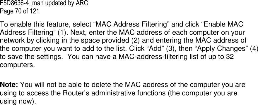
![F5D8636-4_man updated by ARC Page 69 of 121 To restrict Internet access to a single computer for example, enter the IP address of the computer you wish to restrict access to in the IP fields (1). Next, enter “80” in both the port fields (2). Select “Both” (3). Select “Block” (4). You can also select “Always” to block access all of the time. Select the day to start on top (5), the time to start on top (6), the day to end on the bottom (7), and the time to stop (8) on the bottom. Select “Enable” (9). Click “Apply Changes”. The computer at the IP address you specified will now be blocked from Internet access at the times you specified. Note: Be sure you have selected the correct time zone under “Utilities> System Settings> Time Zone”. [FW25.tif] Setting MAC Address Filtering The MAC address filter is a powerful security feature that allows you to specify which computers are allowed on the network. Any computer attempting to access the network that is not specified in the filter list will be denied access. When you enable this feature, you must enter the MAC address of each client (computer) on your network to allow network access to each. (FW26.tif) (1) (3) (2) (4) (5) (6) (7) (8) (9)](https://usermanual.wiki/Belkin/F5D8636A/User-Guide-977677-Page-69.png)
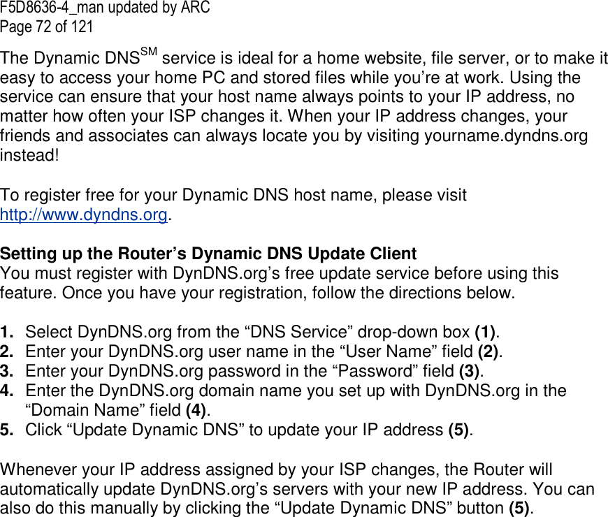
![F5D8636-4_man updated by ARC Page 71 of 121 Enabling the Demilitarized Zone (DMZ) The DMZ feature allows you to specify one computer on your network to be placed outside of the firewall. This may be necessary if the firewall is causing problems with an application such as a game or video conferencing application. Use this feature on a temporary basis. The computer in the DMZ is NOT protected from hacker attacks. [FW27.tif] To put a computer in the DMZ, enter the last digits of its IP address in the IP field and select “Enable”. Click “Apply Changes” for the change to take effect. If you are using multiple static WAN IP addresses, it is possible to select which WAN IP address the DMZ host will be directed to. Type in the WAN IP address you wish the DMZ host to direct to, enter the last two digits of the IP address of the DMZ host computer, select “Enable” and click “Apply Changes”. Using Dynamic DNS The Dynamic DNS service allows you to alias a dynamic IP address to a static host name in any of the many domains DynDNS.org offers, allowing your network computers to be more easily accessed from various locations on the Internet. DynDNS.org provides this service, for up to five host names, free to the Internet community.](https://usermanual.wiki/Belkin/F5D8636A/User-Guide-977677-Page-71.png)
![F5D8636-4_man updated by ARC Page 73 of 121 [FW28.tif] Blocking an ICMP Ping Computer hackers use what is known as “pinging” to find potential victims on the Internet. By pinging a specific IP address and receiving a response from the IP address, a hacker can determine that something of interest might be there. The Router can be set up so it will not respond to an ICMP ping from the outside. This heightens your Router’s security level. (1) (1) (2) (3) (4)](https://usermanual.wiki/Belkin/F5D8636A/User-Guide-977677-Page-73.png)
![F5D8636-4_man updated by ARC Page 74 of 121 [Fw29.tif] To turn off the ping response, select “Block ICMP Ping” (1) and click “Apply Changes”. The Router will not respond to an ICMP ping. Utilities The “Utilities” screen lets you manage different parameters of the Router and perform certain administrative functions.](https://usermanual.wiki/Belkin/F5D8636A/User-Guide-977677-Page-74.png)
![F5D8636-4_man updated by ARC Page 75 of 121 [FW30.tif] Restarting the Router Sometimes it may be necessary to restart or reboot the Router if it begins working improperly. Restarting or rebooting the Router will NOT delete any of your configuration settings. [FW31.tif] Restarting the Router to Restore Normal Operation 1. Click the “Restart Router” button.](https://usermanual.wiki/Belkin/F5D8636A/User-Guide-977677-Page-75.png)
![F5D8636-4_man updated by ARC Page 76 of 121 2. The following message will appear. Click “OK”. [FW32.tif] 3. The following message will appear. Restarting the Router can take up to 60 seconds. It is important not to turn off the power to the Router during the restart. [FW33.tif] 4. A 60-second countdown will appear on the screen. When the countdown reaches zero, the Router will be restarted. The Router home page should appear automatically. If not, type in the Router’s address (default = 192.168.2.1) into the navigation bar of your browser. Restoring Factory Default Settings Using this option will restore all of the settings in the Router to the factory (default) settings. It is recommended that you back up your settings before you restore all of the defaults.](https://usermanual.wiki/Belkin/F5D8636A/User-Guide-977677-Page-76.png)
![F5D8636-4_man updated by ARC Page 77 of 121 [FW34.tif] 1. Click the “Restore Defaults” button. 2. The following message will appear. Click “OK”. [FW35.tif]](https://usermanual.wiki/Belkin/F5D8636A/User-Guide-977677-Page-77.png)
![F5D8636-4_man updated by ARC Page 78 of 121 3. The following message will appear. Restoring the defaults includes restarting the Router. It can take up to 60 seconds. It is important not to turn the power to the Router off during the restart. [FW36.tif] 4. A 60-second countdown will appear on the screen. When the countdown reaches zero, the Router’s defaults will be restored. The Router home page should appear automatically. If it does not, type in the Router’s address (default = 192.168.2.1) into the navigation bar of your browser. Saving a Current Configuration You can save your current configuration by using this feature. Saving your configuration will allow you to restore it later if your settings are lost or changed. It is recommended that you back up your current configuration before performing a firmware update. [FW37.tif]](https://usermanual.wiki/Belkin/F5D8636A/User-Guide-977677-Page-78.png)
![F5D8636-4_man updated by ARC Page 79 of 121 1. Click “Save”. A window called “File Download” will open. Click “Save”. [FW38.tif]](https://usermanual.wiki/Belkin/F5D8636A/User-Guide-977677-Page-79.png)
![F5D8636-4_man updated by ARC Page 80 of 121 2. A window will open that allows you to select the location where you want to save the configuration file. Select a location. You can name the file anything you want, or use the default name “user.conf”. Be sure to name the file so you can locate it yourself later. When you have selected the location and name of the file, click “Save”. [FW39.tif]](https://usermanual.wiki/Belkin/F5D8636A/User-Guide-977677-Page-80.png)
![F5D8636-4_man updated by ARC Page 81 of 121 3. When the save is complete, you will see the window below. Click “Close”. [FW40.tif] 4. The configuration is now saved. Restoring a Previous Configuration This option will allow you to restore a previously saved configuration. [FW41.tif]](https://usermanual.wiki/Belkin/F5D8636A/User-Guide-977677-Page-81.png)
![F5D8636-4_man updated by ARC Page 82 of 121 1. Click “Browse”. A window will open that allows you to select the location of the configuration file. All configuration files end with a “.conf”. Locate the configuration file you want to restore and double-click on it. [FW42.tif] 2. You will be asked if you want to continue. Click “OK”. [FW43.tif] 3. A reminder window will appear. It will take up to 60 seconds for the configuration restoration to complete. Click “OK”.](https://usermanual.wiki/Belkin/F5D8636A/User-Guide-977677-Page-82.png)
![F5D8636-4_man updated by ARC Page 83 of 121 [FW44.tif] 4. A 60-second countdown will appear on the screen. When the countdown reaches zero, the Router’s configuration will be restored. The Router’s home page should appear automatically. If not, type in the Router’s address (default = 192.168.2.1) into the navigation bar of your browser. Updating the Firmware From time to time, Belkin may release new versions of the Router’s firmware. Firmware updates contain feature improvements and fixes to problems that may have existed. When Belkin releases new firmware, you can download the firmware from the Belkin update website and update your Router’s firmware to the latest version. [FW45.tif] (1) (2) (3)](https://usermanual.wiki/Belkin/F5D8636A/User-Guide-977677-Page-83.png)
![F5D8636-4_man updated by ARC Page 84 of 121 Checking for a New Version of Firmware The “Check Firmware” (1) button allows you to instantly check for a new version of firmware. When you click the button, a new browser window will appear informing you that either no new firmware is available or that there is a new version available. If a new version is available, you will have the option to download it. Downloading a New Version of Firmware If you click the “Check Firmware” button and a new version of firmware is available, you will see a screen similar to the one below: [FWUP01.tif] 1. To download the new version of firmware, click “Download”.](https://usermanual.wiki/Belkin/F5D8636A/User-Guide-977677-Page-84.png)
![F5D8636-4_man updated by ARC Page 85 of 121 A window will open that allows you to select the location where you want to save the firmware file. Select a location. You can name the file anything you want, or use the default name. Be sure to locate the file in a place where you can locate it yourself later. When you have selected the location, click “Save”. [FWUP02.tif] 2. When the save is complete, you will see the following window. Click “Close”. [FWUP03.tif]](https://usermanual.wiki/Belkin/F5D8636A/User-Guide-977677-Page-85.png)
![F5D8636-4_man updated by ARC Page 86 of 121 3. The download of the firmware is complete. To update the firmware, follow the next steps in “Updating the Router’s Firmware”. Updating the Router’s Firmware 1. In the “Firmware Update” page, click “Browse”. A window will open that allows you to select the location of the firmware update file. [FWUP04.tif] 2. Browse to the firmware file you downloaded. Select the file by double-clicking on the file name.](https://usermanual.wiki/Belkin/F5D8636A/User-Guide-977677-Page-86.png)
![F5D8636-4_man updated by ARC Page 87 of 121 The “Update Firmware” box will now display the location and name of the firmware file you just selected. Click “Update”. [FW46.tif] 3. You will be asked if you are sure you want to continue. Click “OK”. [FW47.tif] 4. You will see one more message. This message tells you that the Router may not respond for as long as one minute as the firmware is loaded into the Router and the Router is rebooted. Click “OK”.](https://usermanual.wiki/Belkin/F5D8636A/User-Guide-977677-Page-87.png)
![F5D8636-4_man updated by ARC Page 88 of 121 [FW48.tif] 5. A 60-second countdown will appear on the screen. When the countdown reaches zero, the Router firmware update will be complete. The Router home page should appear automatically. If not, type in the Router’s address (default = 192.168.2.1) into the navigation bar of your browser. Changing System Settings The “System Settings” page is where you can enter a new administrator password, set the time zone, enable remote management, and turn on and off the NAT function of the Router. Setting or Changing the Administrator Password The Router ships with NO password entered. If you wish to add a password for greater security, you can set a password here. Write down your password and keep it in a safe place, as you will need it if you need to log into the Router in the future. It is also recommended that you set a password if you plan to use the remote management feature of your Router. [FW49.tif] Changing the Login Time-Out Setting The login time-out option allows you to set the period of time that you can be logged into the Router’s advanced setup interface. The timer starts when there has been no activity. For example, imagine you have made some changes in the advanced setup interface, then left your computer alone without clicking “Logout”. Assuming the time-out is set to 10 minutes, 10 minutes after you leave, the login session will expire. You will have to log into the Router again to make any more](https://usermanual.wiki/Belkin/F5D8636A/User-Guide-977677-Page-88.png)
![F5D8636-4_man updated by ARC Page 89 of 121 changes. The login time-out option is for security purposes and the default is set to 10 minutes. Note: Only one computer can be logged into the Router’s advanced setup interface at one time. Setting the Time and Time Zone The Router keeps time by connecting to a Simple Network Time Protocol (SNTP) server. This allows the Router to synchronize the system clock to the global Internet. The synchronized clock in the Router is used to record the security log and control client filtering. Select the time zone that you reside in. You have the option to select a primary and a backup NTP server to keep your Router’s clock synchronized. Select your desired NPT server from the drop-down box, or simply keep it as is. If you reside in an area that observes daylight saving, then place a check mark in the box next to “Enable Daylight Saving”. The system clock may not update immediately. Allow at least 15 minutes for the Router to contact the time servers on the Internet and get a response. You cannot set the clock yourself. [FW49.tif] Enabling Remote Management Before you enable this advanced feature of your Belkin Router, MAKE SURE YOU HAVE SET THE ADMINISTRATOR PASSWORD. Remote management allows you to make changes to your Router’s settings from anywhere on the Internet. There are two methods of remotely managing the Router. The first is to allow access to the Router from anywhere on the Internet by selecting “Any IP address can remotely manage the Router”. By typing in your WAN IP address from any computer on the Internet, you will be presented with a login screen where you need to type in the password of your Router. The second method is to allow a specific IP address only to remotely manage the Router. This is more secure, but less convenient. To use this method, enter the IP address you know you will be accessing the Router from in the space provided and select “Only this IP address can remotely manage the Router”. Before you enable this function, it is STRONGLY RECOMMENDED that you set your](https://usermanual.wiki/Belkin/F5D8636A/User-Guide-977677-Page-89.png)
![F5D8636-4_man updated by ARC Page 90 of 121 administrator password. Leaving the password empty will potentially open your Router to intrusion. Advanced Feature: The “Remote Access Port” option allows you to configure the desired “Remote Access Port for Remote Management” feature. The default access port is set to port 8080. [FW49.tif] Enabling/Disabling UPnP UPnP (Universal Plug-and-Play) is yet another advanced feature offered by your Belkin Router. It is a technology that offers seamless operation of voice messaging, video messaging, games, and other applications that are UPnP-compliant. Some applications require the Router’s firewall to be configured in a specific way to operate properly. This usually requires opening TCP and UDP ports, and in some instances, setting trigger ports. An application that is UPnP-compliant has the ability to communicate with the Router, basically “telling” the Router which way it needs the firewall configured. The Router ships with the UPnP feature disabled. If you are using any applications that are UPnP-compliant, and wish to take advantage of the UPnP features, you can enable the UPnP feature. Simply select “Enable” in the “UPnP Enabling” section of the “Utilities” page. Click “Apply Changes” to save the change. [FW49.tif]](https://usermanual.wiki/Belkin/F5D8636A/User-Guide-977677-Page-90.png)
![F5D8636-4_man updated by ARC Page 91 of 121 Enabling/Disabling Auto Firmware Update This innovation provides the Router with the built-in capability to automatically check for a new version of firmware and alert you that the new firmware is available. When you log into the Router’s advanced interface, the Router will perform a check to see if new firmware is available. If so, you will be notified. You can choose to download the new version or ignore it. [FW49.tif] Manually Configuring Network Settings Set up the computer that is connected to the cable or DSL modem FIRST using these steps. You can also use these steps to add computers to your Router after the Router has been set up to connect to the Internet. Manually Configuring Network Settings in Mac OS up to 9.x](https://usermanual.wiki/Belkin/F5D8636A/User-Guide-977677-Page-91.png)
![F5D8636-4_man updated by ARC Page 92 of 121 1. Pull down the Apple menu. Select “Control Panels” and select “TCP/IP”. 2. You will see the TCP/IP control panel. Select “Ethernet Built-In” or “Ethernet” in the “Connect via:” drop-down menu (1). [xxxxxxx][use current image] [keep] 3. Next to “Configure” (2), if “Manually” is selected, your Router will need to be set up for a static IP connection type. Write the address information in the table below. You will need to enter this information into the Router. [MacOS9 chart.tif] [use current image] [keep] (1) (2)](https://usermanual.wiki/Belkin/F5D8636A/User-Guide-977677-Page-92.png)
![F5D8636-4_man updated by ARC Page 93 of 121 4. If not already set, at “Configure:”, choose “Using DHCP Server”. This will tell the computer to obtain an IP address from the Router. [xxxxxxx] [use current image] [keep] 5. Close the window. If you made any changes, the following window will appear. Click “Save”. [xxxxxxx] [use current image] [keep] Restart the computer. When the computer restarts, your network settings are now configured for use with the Router. Manually Configuring Network Settings in Mac OS X 1. Click on the “System Preferences” icon. [xxxxxxx] [use current image] [keep] 2. Select “Network” (1) from the “System Preferences” menu. [xxxxxxx] [use current image] [keep] 2 2 (1)](https://usermanual.wiki/Belkin/F5D8636A/User-Guide-977677-Page-93.png)
![F5D8636-4_man updated by ARC Page 94 of 121 3. Select “Built-in Ethernet” (2) next to “Show” in the Network menu. [xxxxxxx] [use current image] [keep] 4. Select the “TCP/IP” tab (3). Next to “Configure” (4), you should see “Manually” or “Using DHCP”. If you do not, check the PPPoE tab (5) to make sure that “Connect using PPPoE” is NOT selected. If it is, you will need to configure your Router for a PPPoE connection type using your user name and password. 5. If “Manually” is selected, your Router will need to be set up for a static IP connection type. Write the address information in the table below. You will need to enter this information into the Router. [MacOS9 chart.tif] [use current image] [keep] 6. If not already selected, select “Using DHCP” next to “Configure” (4), then click “Apply Now”. Your network settings are now configured for use with the Router. (2) (3) (4) (5)](https://usermanual.wiki/Belkin/F5D8636A/User-Guide-977677-Page-94.png)
![F5D8636-4_man updated by ARC Page 96 of 121 4. In the “Local Area Connection Properties” window, click “Internet Protocol (TCP/IP)” and click the “Properties” button. The following screen will appear: [XP TCPIP.tif] [use current image] [keep] 5. If “Use the following IP address” (2) is selected, your Router will need to be set up for a static IP connection type. Write the address information the table below. You will need to enter this information into the Router. [win2k settings chart.tif] [use current image] [keep] 6. If not already selected, select “Obtain an IP address automatically” (1) and “Obtain DNS server address automatically” (3). Click “OK”. Your network settings are now configured for use with the Router. (1) (2) (3)](https://usermanual.wiki/Belkin/F5D8636A/User-Guide-977677-Page-96.png)
![F5D8636-4_man updated by ARC Page 97 of 121 Manually Configuring Network Settings in Windows 98 or Me 1. Right-click on “My Network Neighborhood” and select “Properties” from the drop-down menu. 2. Select “TCP/IP -> settings” for your installed network adapter. You will see the following window. [98 Me IP properties.tif] [use current image] [keep] 3. If “Specify and IP address” is selected, your Router will need to be set up for a static IP connection type. Write the address information in the table below. You will need to enter this information into the Router. 4. Write the IP address and subnet mask from the “IP Address” tab (3). 5. Click the “Gateway” tab (2). Write the gateway address down in the chart. 6. Click the “DNS Configuration” tab (1). Write the DNS address(es) in the chart. (1) (2) (3)](https://usermanual.wiki/Belkin/F5D8636A/User-Guide-977677-Page-97.png)
![F5D8636-4_man updated by ARC Page 98 of 121 [win2k settings chart.tif] [keep] [use current image] 7. If not already selected, select “Obtain IP address automatically” on the IP address tab. Click “OK”. Restart the computer. When the computer restarts, your network settings are now configured for use with the Router.](https://usermanual.wiki/Belkin/F5D8636A/User-Guide-977677-Page-98.png)
![F5D8636-4_man updated by ARC Page 99 of 121 Recommended Web Browser Settings In most cases, you will not need to make any changes to your web browser’s settings. If you are having trouble accessing the Internet or the Web-Based Advanced User Interface, then change your browser’s settings to the recommended settings in this section. Microsoft® Internet Explorer 4.0 or Higher 1. Start your web browser. Select “Tools” then “Internet Options”. [insert Internet_options.tif] 2. In the “Internet Options” screen, there are three selections: “Never dial a connection”, “Dial whenever a network connection is not present”, and “Always dial my default connection”. If you can make a selection, select “Never dial a connection”. If you cannot make a selection, go to the next step.](https://usermanual.wiki/Belkin/F5D8636A/User-Guide-977677-Page-99.png)
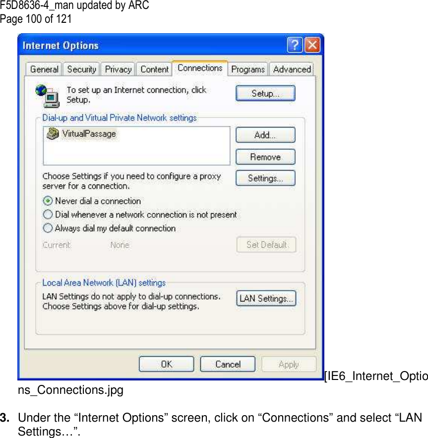
![F5D8636-4_man updated by ARC Page 101 of 121 4. Make sure there are no check marks next to any of the displayed options: “Automatically detect settings”, “Use automatic configuration script”, and “Use a proxy server”. Click “OK”. Then click “OK” again in the “Internet Options” page. [IE6_Internet_Options_Connections_LAN_Settings.jpg Netscape® Navigator® 4.0 or Higher 1. Start Netscape. Click on “Edit” then “Preferences”. 2. In the “Preferences” window, click on “Advanced” then select “Proxies”. In the “Proxies” window, select “Direct connection to the Internet”. [NS6 Setup 1.tif]](https://usermanual.wiki/Belkin/F5D8636A/User-Guide-977677-Page-101.png)
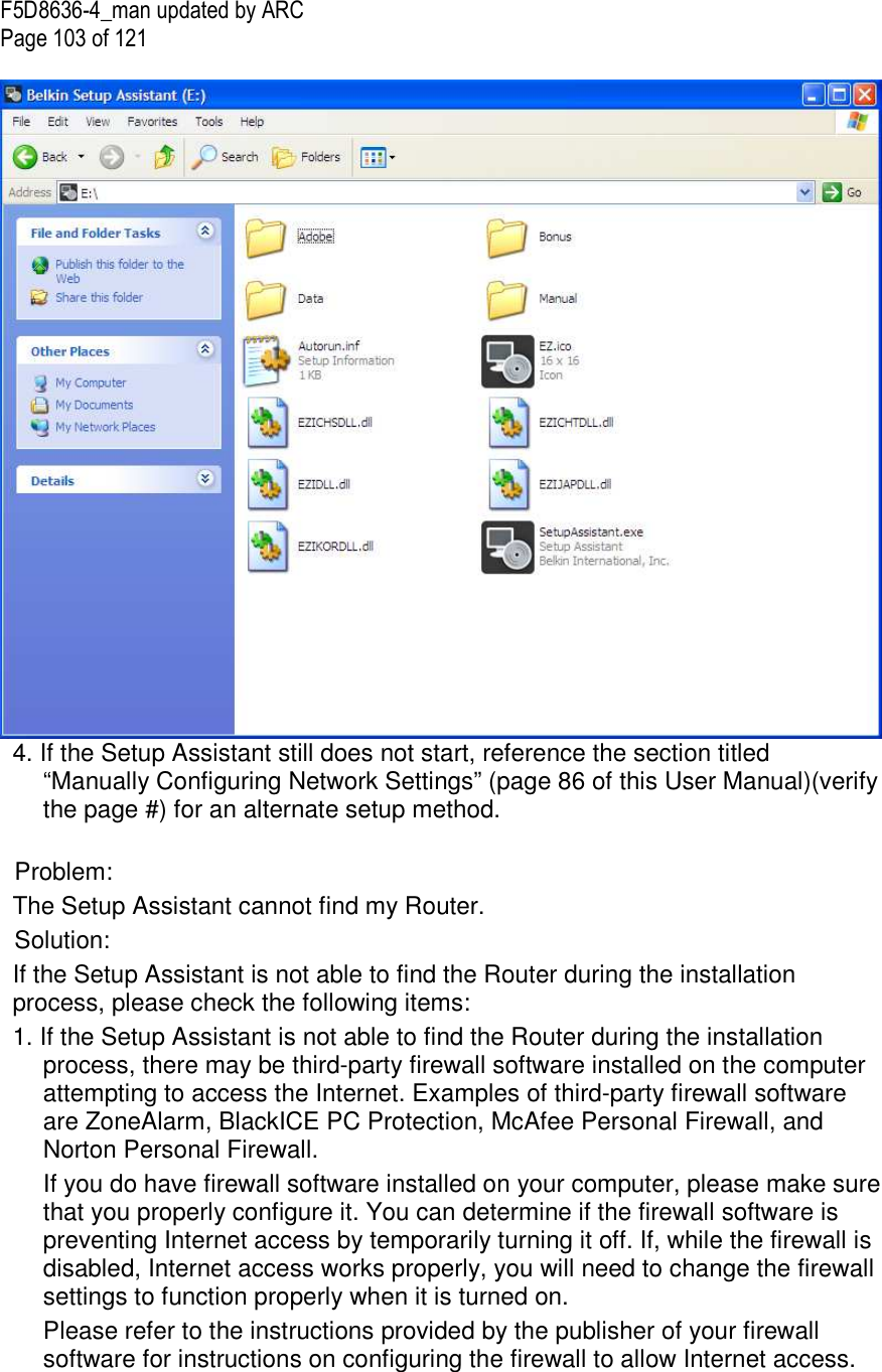
![F5D8636-4_man updated by ARC Page 102 of 121 Troubleshooting Problem: Installation CD does not automatically start. Solution: If the CD-ROM does not start the Setup Assistant automatically, it could be that the computer is running other applications that are interfering with the CD drive. 1. If the Setup Assistant screen does not appear within 15–20 seconds, open up your CD-ROM drive by double-clicking on the “My Computer” icon that is located on your desktop. 2. Next, double-click on the CD-ROM drive that the Setup Assistant Software CD has been placed in to start the installation. [encircle on “Belkin Setup Assistant” icon.] 3. The Setup Assistant should start within a few seconds. If, instead, a window appears showing the files on the CD, double-click on the icon labeled “SetupAssistant.exe”. [encircle on “SetupAssistant.exe” icon.]](https://usermanual.wiki/Belkin/F5D8636A/User-Guide-977677-Page-102.png)
![F5D8636-4_man updated by ARC Page 110 of 121 I am having difficulty setting up Wired Equivalent Privacy (WEP) security on a Belkin client card (Wireless Network Card or Adapter). Solution: The client card must use the same key as the G Wireless Router or access point. For instance, if your Wireless Router or access point uses the key 00112233445566778899AABBCC, then the client card must be set to the exact same key. 1. Double-click the “Signal Indicator” icon to bring up the “Wireless Network Utility” screen. The “Advanced” button will allow you to view and configure more options of your client card. 2. Once the “Advanced” button is clicked, the Belkin Wireless LAN Utility will appear. This Utility will allow you to manage all the advanced features of the Belkin client card. 3. Under the “Wireless Network Properties” tab, select a network name from the “Available Networks” list and click the “Properties” button. 4. Under “Data Encryption”, select “WEP”. 5. Ensure the box “The key is provided for me automatically” at the bottom is unchecked. If you are using this computer to connect to a corporate network, please consult your network administrator if this box needs to be checked. 6. Type your WEP key in the “Network key” box. Important: A WEP key is a combination of numbers and letters from A–F and 0–7. For 128-bit WEP, you need to enter 26 keys. This network key needs to match the key you assign to your G Wireless Router or access point. For example: C3030FAF4BB2C3D44BC3D4E7E4 = 128-bit key 8. Click “OK”, and then “Apply” to save the settings. If you are NOT using a Belkin wireless client card, please consult the manufacturer’s user manual for that wireless client card. Problem: Do Belkin products support WPA? Solution: Note: To use WPA security, all your clients must be upgraded to drivers and software that support it. At the time of this publication, a security patch download is available, for free, from Microsoft. This patch works only with the Windows XP operating system. Download the patch here: http://www.microsoft.com/downloads/details.aspx?FamilyID=009d8425-ce2b-47a4-abec-274845dc9e91&displaylang=en [keep hyperlink since this will be on CD]](https://usermanual.wiki/Belkin/F5D8636A/User-Guide-977677-Page-110.png)
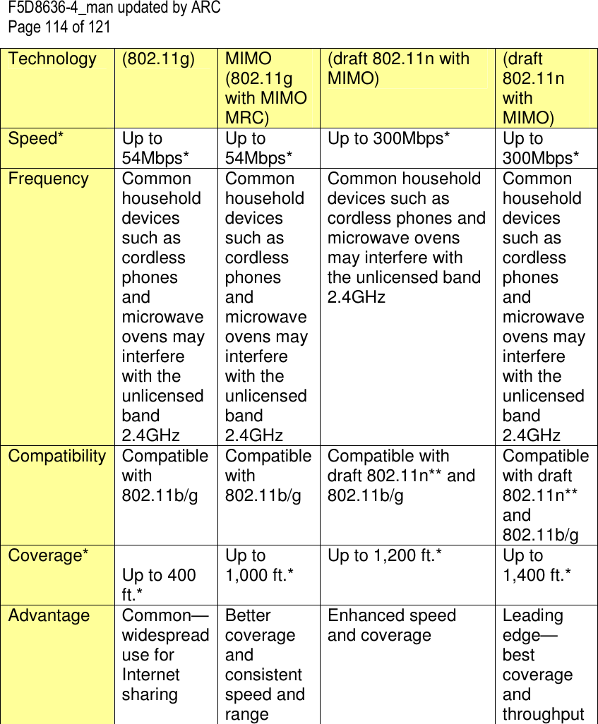
![F5D8636-4_man updated by ARC Page 113 of 121 http://www.microsoft.com/downloads/details.aspx?FamilyID=009d8425-ce2b-47a4-abec-274845dc9e91&displaylang=en [keep hyperlink since this is on CD] Note: The file that Microsoft has made available works only with Windows XP. Other operating systems are not supported at this time. You also need to ensure that the wireless card manufacturer supports WPA and that you have downloaded and installed the latest driver from their support site. Supported Operating Systems: • Windows XP Professional • Windows XP Home Edition Enabling WPA-PSK 1. In systems running Windows XP, click “Start > Control Panel > Network Connections”. 2. Right-click on the “Wireless Networks” tab. The “Wireless Network Connection Properties” screen appears. Ensure the “Use Windows to configure my wireless network settings” box is checked. 3. Under the “Wireless Networks” tab, click the “Configure” button, and you will see the client card properties screen. 4. For a home or small business user, select “WPA-PSK” under “Network Administration”. 5. Select “TKIP” or “AES” under “Date Encryption”. This setting will have to be identical to the G Wireless Router or access point that you set up. 6. Type in your encryption key in the “Network key” box. Important: Enter your pre-shared key. This can be from eight to 63 characters and can be letters, numbers, or symbols. This same key must be used on all of the clients that you set up. 7. Click “OK” to apply settings. What’s the difference between 802.11b, 802.11g, 802.11a, and draft 802.11n? Currently there are four levels of wireless networking standards, which transmit data at very different maximum speeds. Each is based on the designation for certifying network standards. The most common wireless networking standard, 802.11b, transmits information at 11Mbps; 802.11a and 802.11g work at 54Mbps; and draft 802.11n works at 300Mbps. See the following chart for more detailed information. Wireless Comparison Chart [Use same chart as 8233] Wireless G G Plus N MIMO N1 MIMO](https://usermanual.wiki/Belkin/F5D8636A/User-Guide-977677-Page-113.png)
![F5D8636-4_man updated by ARC Page 119 of 121 Belkin International, Inc., Limited Lifetime Product Warranty What this warranty covers. Belkin International, Inc. (“Belkin”) warrants to the original purchaser of this Belkin product that the product shall be free of defects in design, assembly, material, or workmanship. What the period of coverage is. Belkin warrants the Belkin product for the lifetime of the product. What will we do to correct problems? Product Warranty. Belkin will repair or replace, at its option, any defective product free of charge (except for shipping charges for the product). What is not covered by this warranty? All above warranties are null and void if the Belkin product is not provided to Belkin for inspection upon Belkin’s request at the sole expense of the purchaser, or if Belkin determines that the Belkin product has been improperly installed, altered in any way, or tampered with. The Belkin Product Warranty does not protect against acts of God such as flood, lightning, earthquake, war, vandalism, theft, normal-use wear and tear, erosion, depletion, obsolescence, abuse, damage due to low voltage disturbances (i.e. brownouts or sags), non-authorized program, or system equipment modification or alteration. How to get service. To get service for your Belkin product you must take the following steps: 1. Contact Belkin Tech Support at the number listed on page 99 [Need to verify this page # ], within 15 days of the Occurrence. Be prepared to provide the following information: a. The part number of the Belkin product. b. Where you purchased the product. c. When you purchased the product. d. Copy of original receipt. 2. Your Belkin Customer Service Representative will then instruct you on how to forward your receipt and Belkin product and how to proceed with your claim. Belkin reserves the right to review the damaged Belkin product. All costs of shipping the Belkin product to Belkin for inspection shall be borne solely by the purchaser. If Belkin determines, in its sole discretion, that it is impractical to ship the damaged equipment to Belkin, Belkin may designate, in its sole discretion, an equipment repair facility to inspect and estimate the cost to repair such equipment. The cost, if any, of shipping the equipment to and from such repair](https://usermanual.wiki/Belkin/F5D8636A/User-Guide-977677-Page-119.png)